×

Search Results

Web Pages

Images

    • <
    • 1
    • >
  • machines
    • Haas Vertical Mills
      Vertical Mills
      • Vertical Mills
      • VF Series
      • Universal Machines
      • VR Series
      • Pallet-Changing VMCs
      • Mini Mills
      • Mold Machines
      • Drill/ Tap/ Mill Series
      • Toolroom Mills
      • Compact Mills
      • Gantry Series
      • Vertical Mill/Turn
      • Extra-Large VMC
      • Desktop Mill
      • Control Simulator
      • Mill Auto Parts Loader
    • Product Image
      Multi-Axis Solutions
      • Multi-Axis Solutions
      • 5-Axis Mills
      • Y-Axis Lathes
    • Haas Lathes
      Lathes
      • Lathes
      • ST Series
      • Dual-Spindle
      • Toolroom Lathes
      • Chucker Lathe
      • Haas Bar Feeder V2
      • Lathe Auto Parts Loader
    • Haas Horizontal Mills
      Horizontal Mills
      • Horizontal Mills
      • 50-Taper
      • 40-Taper
    • Haas Rotaries & Indexers
      Rotaries & Indexers
      • Rotaries & Indexers
      • Rotary Tables
      • Indexers
      • 5-Axis Rotaries
      • Extra-Large Rotaries
    • Product Image
      Automation Systems
      • Automation Systems
      • Robot Systems
      • Automatic Parts Loaders
      • Pallet Pool Systems
      • Haas Bar Feeder
      • Models
    • QUICK LINKS Special Series  Special Series  PRICE LIST PRICE LIST BUILD & PRICE BUILD & PRICE WHAT’S NEW WHAT’S NEW
      SHOPPING TOOLS
      • Build & Price a Haas
      • Price List
      • Available Inventory
      • CNCA Financing
      WANT TO TALK TO SOMEONE?

      A Haas Factory Outlet (HFO) can answer your questions, and walk you through your best options.

      CONTACT YOUR DISTRIBUTOR >
  • Options
    • Product Image
      Spindles
      • Spindles
    • Product Image
      Tool Changers
      • Tool Changers
    • Product Image
      4th- | 5th-Axis
      • 4th- | 5th-Axis
    • Product Image
      Turrets & Live Tooling
      • Turrets & Live Tooling
    • Product Image
      Probing
      • Probing
    • Haas Chip & Coolant Management
      Chip & Coolant Management
      • Chip & Coolant Management
    • The Haas Control
      The Haas Control
      • The Haas Control
    • Product Image
      Product Options
      • Product Options
    • Product Image
      Tooling & Fixturing
      • Tooling & Fixturing
    • Product Image
      Workholding
      • Workholding
    • Product Image
      5-Axis Solutions
      • 5-Axis Solutions
      • 5 Easy Steps to 5-Axis
    • Product Image
      Automation
      • Automation
    • QUICK LINKS Special Series  Special Series  PRICE LIST PRICE LIST BUILD & PRICE BUILD & PRICE WHAT’S NEW WHAT’S NEW
      SHOPPING TOOLS
      • Build & Price a Haas
      • Price List
      • Available Inventory
      • CNCA Financing
      WANT TO TALK TO SOMEONE?

      A Haas Factory Outlet (HFO) can answer your questions, and walk you through your best options.

      CONTACT YOUR DISTRIBUTOR >
  • Why Haas
      Discover the Haas Difference
      Why Haas MyHaas HTEC Network Industry 4.0 Haas Certification Customer Testimonials
  • Service
    • SEARCH ALARM CODES
      Search
    • Troubleshooting Guides and How-To Procedures
      • Product Image
        Troubleshooting Guides
      • Product Image
        How To Procedures
    • Manuals
      • Product Image
        Operator Manuals
      • Product Image
        Interactive Service Manuals
  • Videos
  • MyHaas – One Place for Everything

    • Compare Quotes
      • Compare Quotes

    • About MyHaas
      • About MyHaas

    • Haas CNC Certification Program
      • Haas CNC Certification Program

    • Haas CNC Certification Program-Redirect
      • Haas CNC Certification Program-Redirect

    • Haas CNC Certification Program
      • Haas CNC Certification Program

    • Haas Learning Resources
      • Haas Learning Resources

    • Haas Global Learning Resources
      • Haas Global Learning Resources
    • QUICK LINKS Special Series  Special Series  PRICE LIST PRICE LIST BUILD & PRICE BUILD & PRICE WHAT’S NEW WHAT’S NEW
      SHOPPING TOOLS
      • Build & Price a Haas
      • Price List
      • Available Inventory
      • CNCA Financing
      WANT TO TALK TO SOMEONE?

      A Haas Factory Outlet (HFO) can answer your questions, and walk you through your best options.

      CONTACT YOUR DISTRIBUTOR >
  • Haas Tooling

      Mill Toolholding

      End Mill Holders
      Shell Mill Holders
      Shrink Fit Holders
      ER Collet Chucks
      Milling Chucks, Collets & Kits
      Drill Chucks
      Pull Studs
      Mill Toolholding Kits

      Mill Workholding

      Vises
      Mill Vise Jaws
      Workholding Accessories

      Milling

      Shell Mill Bodies
      Milling Inserts
      End Mills
      End Mill Kits
      Chamfer Mills & Inserts
      Indexable End Mill Bodies

      HSK Toolholders

      HSK ER Collet Chucks
      HSK Shell Mill Holders

      Lathe Tooling

      Cut-Off Tooling
      Cut-Off Tooling Kits
      Turning Inserts
      Grooving Tools
      Small ID Grooving & Threading Tools
      Threading Inserts
      Threading Toolholding
      ID Toolholding
      OD Toolholding

      Lathe Workholding

      Live Centers

      ER Collet

      ER Collets & Accessories
      ER Collet Kits

      Holemaking

      Carbide Drills
      Indexable Drill Bodies
      Indexable Drill Inserts
      Indexable Drilling Kits
      Modular Drill Bodies
      Modular Drill Heads
      Cobalt Drills & Sets
      Center Drills

      Threading

      Taps
      Threading Inserts
      Threading Toolholders

      Tool Management

      Tool Presetting Machines

      Tooling Accessories

      Spindle Taper Cleaner
      Spindle Test Bars
      Haas Shop Lift

      Tool Kits

      End Mill Kits
      Indexable Drilling Kits
      Indexable Milling Kits
      Mill Toolholding Kits

      Apparel & Accessories

      Accessories
      Apparel

      Part #

      Mill Toolholding Mill Workholding Milling HSK Toolholders Lathe Tooling Lathe Workholding ER Collet Holemaking Threading Tool Management Tooling Accessories Tool Kits Apparel & Accessories
  • Contact Us

My Cart
MyHaas Welcome,
!
Haas Tooling Guest Order History MyHaas/HaasConnect Sign In Register Haas Tooling My Account Order History Return History MyHaas/HaasConnect Sign Out Welcome, My Machines Latest Activity My Quotes My Account My Users Sign Out
Find A Dealer
  1. Select Language
    1. English
    2. Deutsch
    3. Español
    4. Français
    5. Italiano
    6. Português
    7. Česky
    8. Dansk
    9. Nederlands
    10. Magyar
    11. Polski
    12. Svenska
    13. Русский
    14. Türkçe
    15. 中文
    16. Suomi
    17. Norsk
    18. الإنجليزية
    19. Български
    20. Hrvatski
    21. Ελληνικά
    22. Română
    23. Slovenský
    24. Slovenščina
    25. 한국어
    26. 日本語
Search
×

Search Results

Web Pages

Images

    • <
    • 1
    • >

Chip Conveyor

Chip Removal and Coolant - Service Manual


  • Chip and Coolant - Introduction
  • Standard Flood Coolant
  • Oil Skimmer
  • Chip Auger
  • Chip Conveyor
  • Through-Tool Air Blast
  • ST Series - Chip Conveyor - Installation
  • TL-1/2 Chip Conveyor - Installation
  • Chip Conveyor - Motor Replacement
  • Chip Conveyor System - Troubleshooting
Recently Updated

Chip Conveyor - Field Installation - ST Series - NGC


AD0435

Document Applies to these Parts

Machine Chip Conveyor Kit
ST-10/10V/10Y/10YV/ 15/15Y
93-3857
ST-20/20V/20Y/20YV/ 25/25Y
93-3858
ST-20/20V/20Y/20YV/15/15Y [2018]
93-3859
ST-30/30Y/30YEU/35/35Y
93-3860
ST-40/45
93-3861
ST-40L/45L/50/55
93-3862

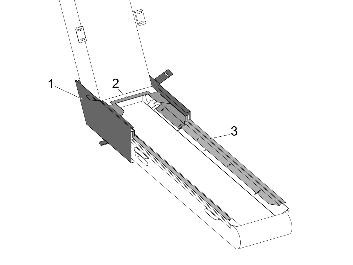
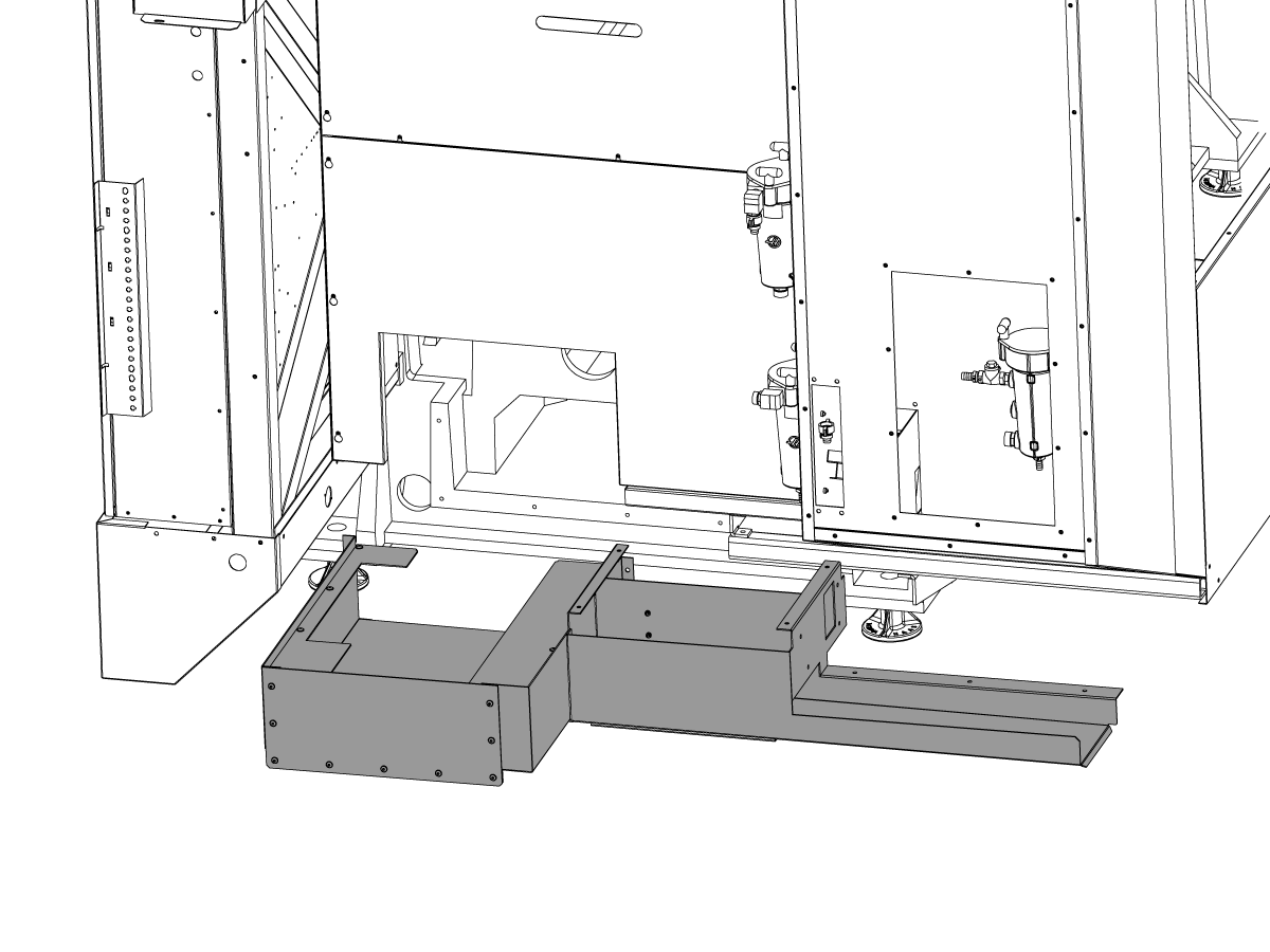
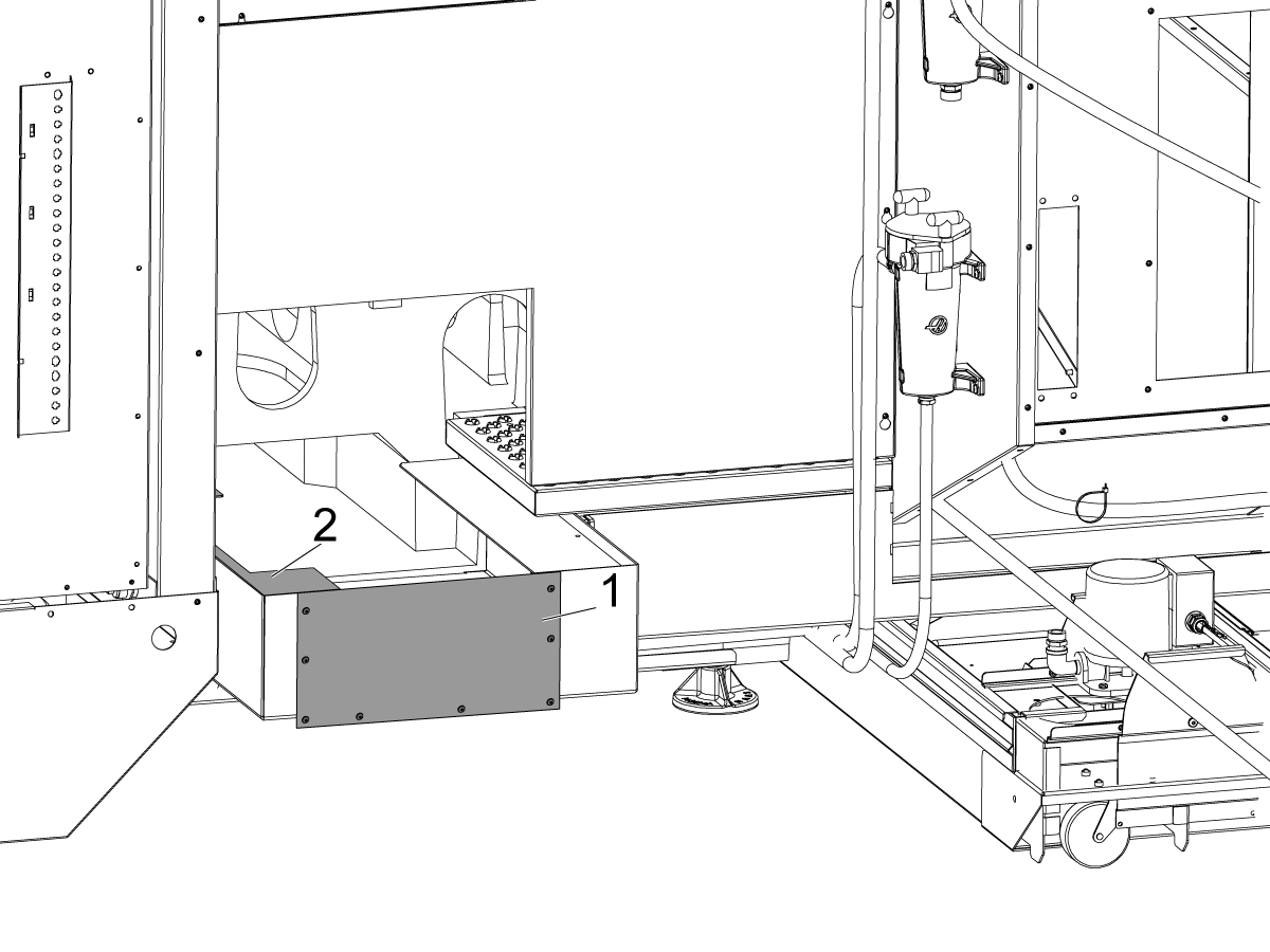
Chip Conveyor - Field Installation - Introduction

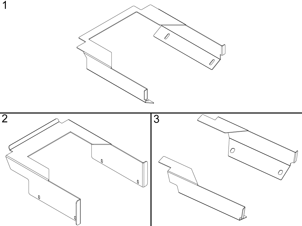
  1. Conveyor Trough Cover
  2. Drip Tray
  3. Safety Skirt

Chip Conveyor - Field Installation

1

Download the Conveyor patch file from the Haas Service Portal and install it on the machine.  Refer to: Patch File Load Uninstall - NGC.

2

If the machine has a chip tray (ST-10/15) remove it.

3

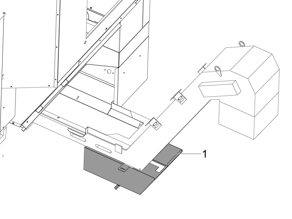
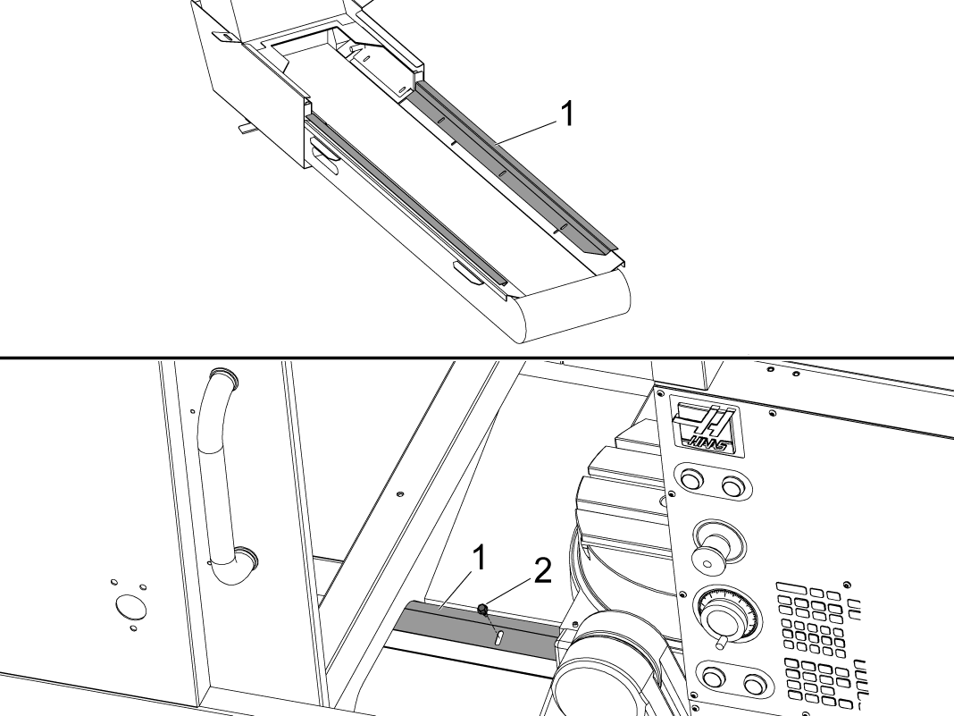
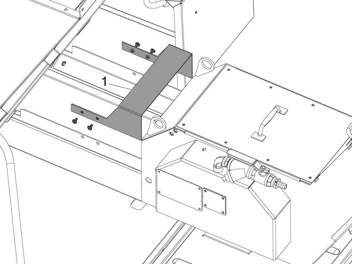
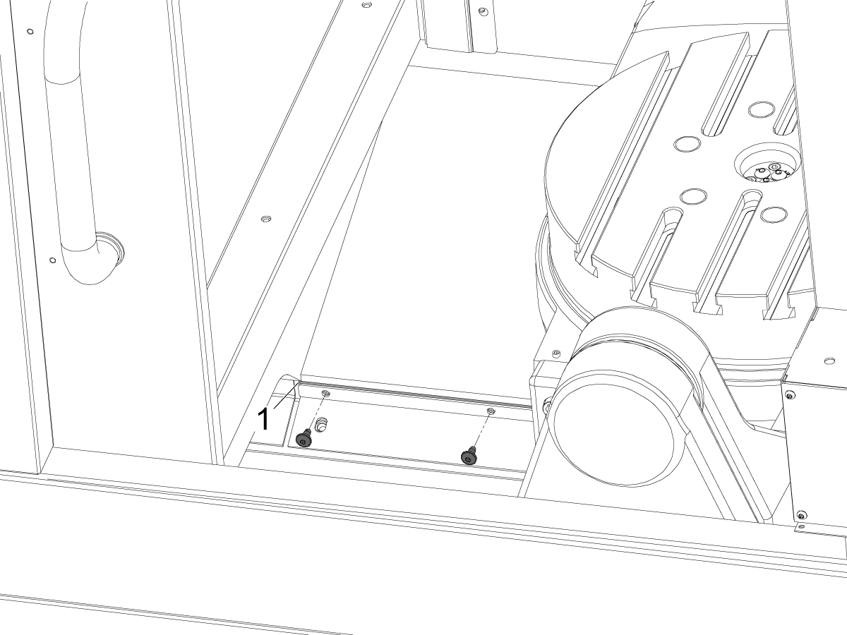
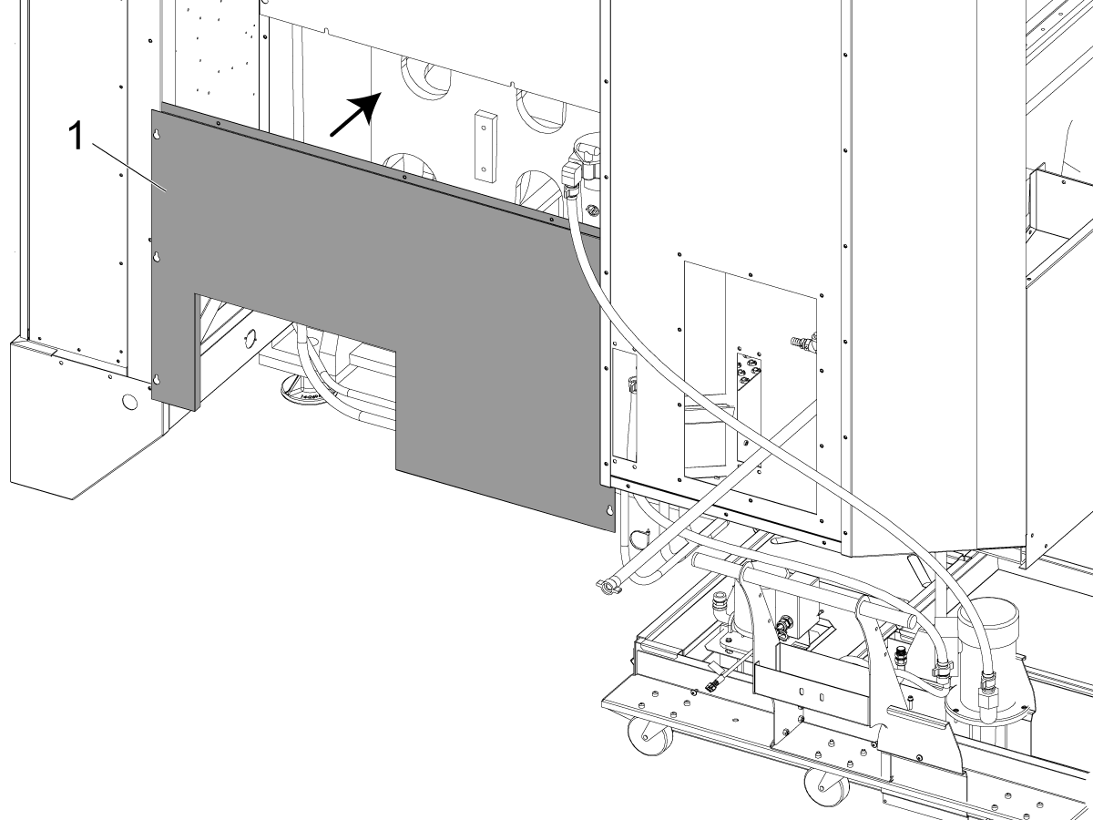
Attach the trough cover [1] to the CHIP CONVEYOR.

For a Jorgensen conveyor, install the (8) hex head screws and washers to attach the trough cover and lock the conveyor in the operating position as shown.

For a Hennig conveyor, install the (4) hex head screws and washers to attach the trough cover and lock the conveyor in the operating position.

4

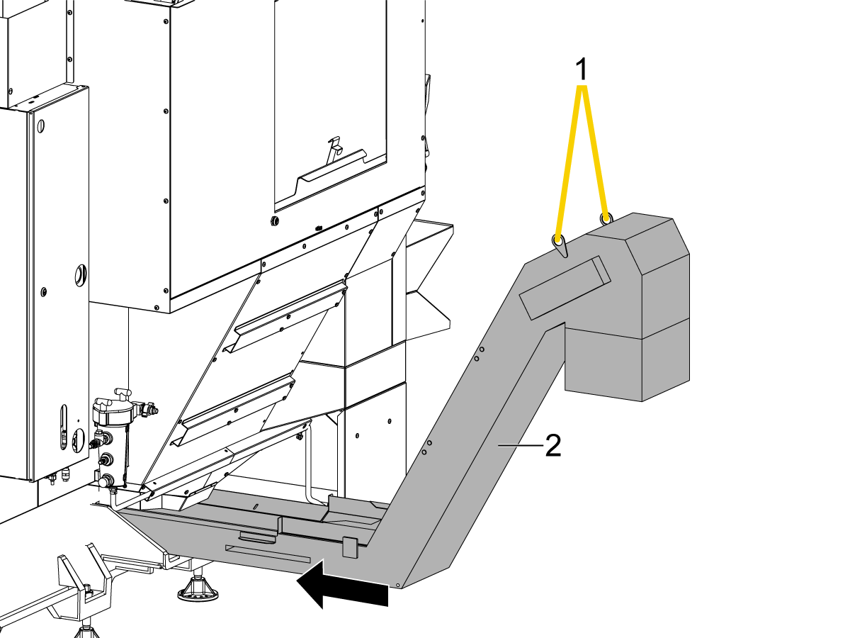
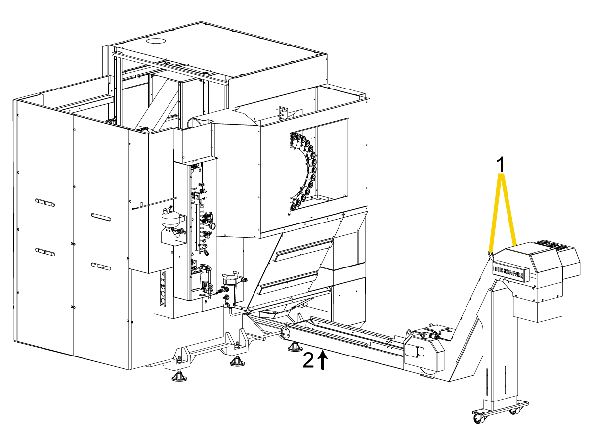
 Caution: The conveyor is heavy.

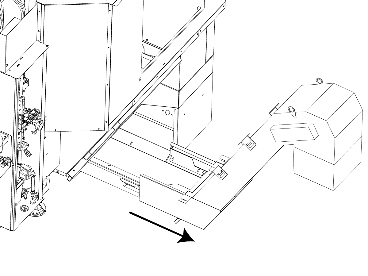
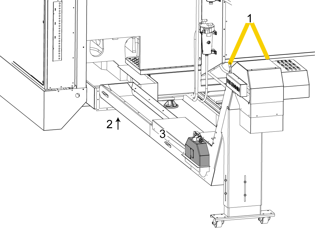
Put a piece of "1" bar stock [1] into the holes in the lifting tabs. Lift the CHIP CONVEYOR [A] with a lift strap on the bar stock and a forklift (not shown).

Raise the conveyor until it is level with lathe chip conveyor pocket.

 Note: For ST-40/45/40L/45L/50/55 machines with a 95 Gallon Coolant Tank procede to the next step.

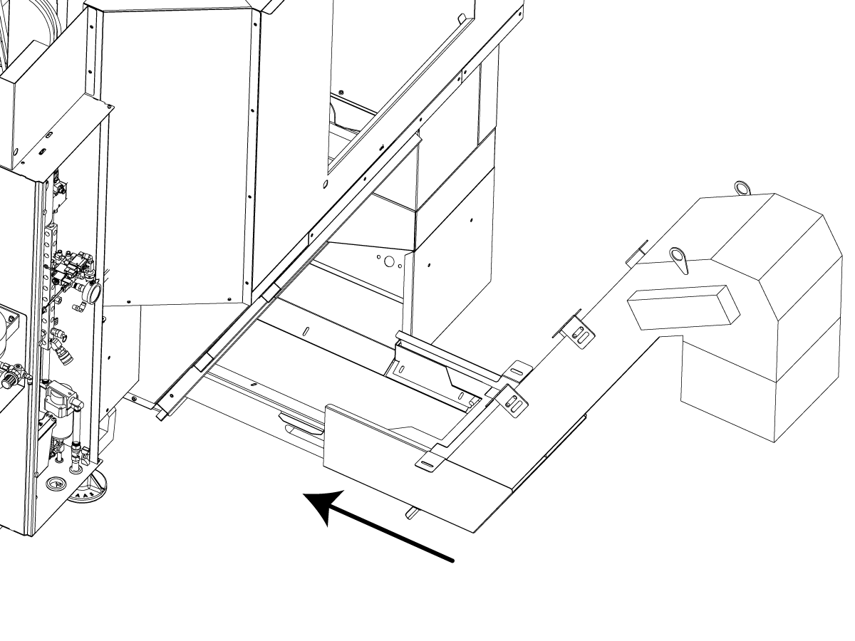
Push on the bar stock to move the conveyor into the machine. This may take (2) or more people.

5

 Note: This step applies to ST-40/45/40L/45L/50/55 machines with a 95 Gallon Coolant Tank.

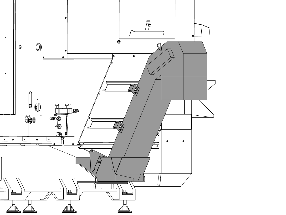
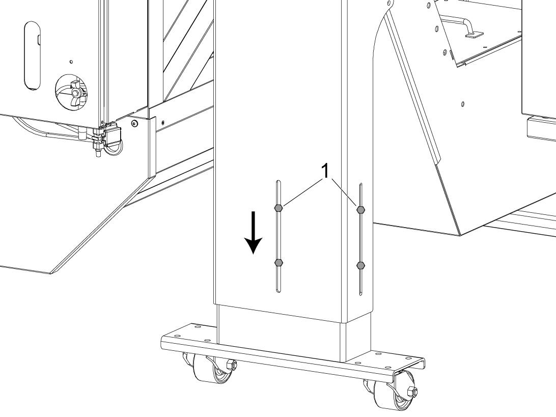
  • Lower the conveyor legs.
  • Push the conveyor in until the conveyor legs almost touches the coolant tank.
  • Remove the legs from the conveyor.
  • Push the conveyor the rest of the way in.
  • To prevent a coolant leak install the bolts back into the tapped holes.

6

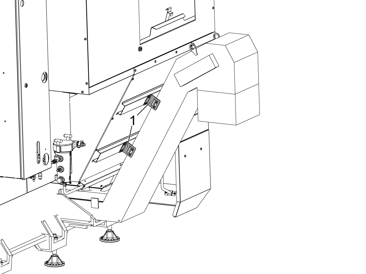
 Note: This step applies to ST-10, ST-20, and ST-30 lathes only.

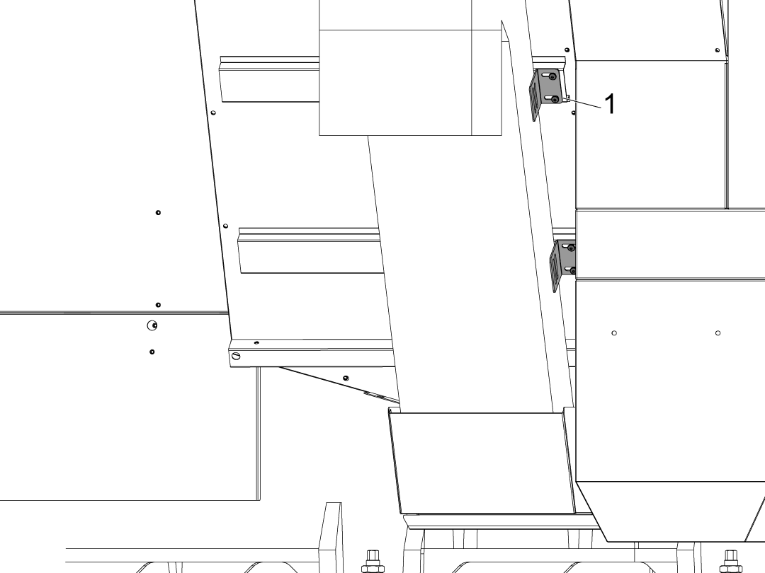
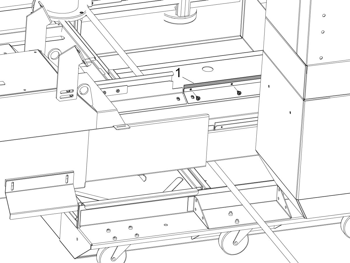
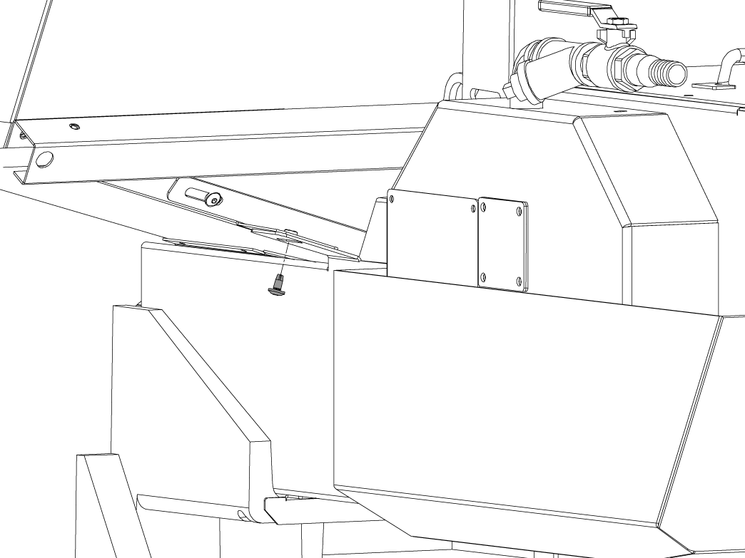
For a Hennig conveyor, install the (4) 1/4-20 X 1/2" button head cap screws (BHCS) to lock the conveyor in the operating position as shown.

For a Jorgensen conveyor, install the (2) 1/4-20 X 1/2" BHCS to lock the conveyor in the operating position.

7

 Note: This step applies to ST-10, ST-20, and ST-30 lathes only.

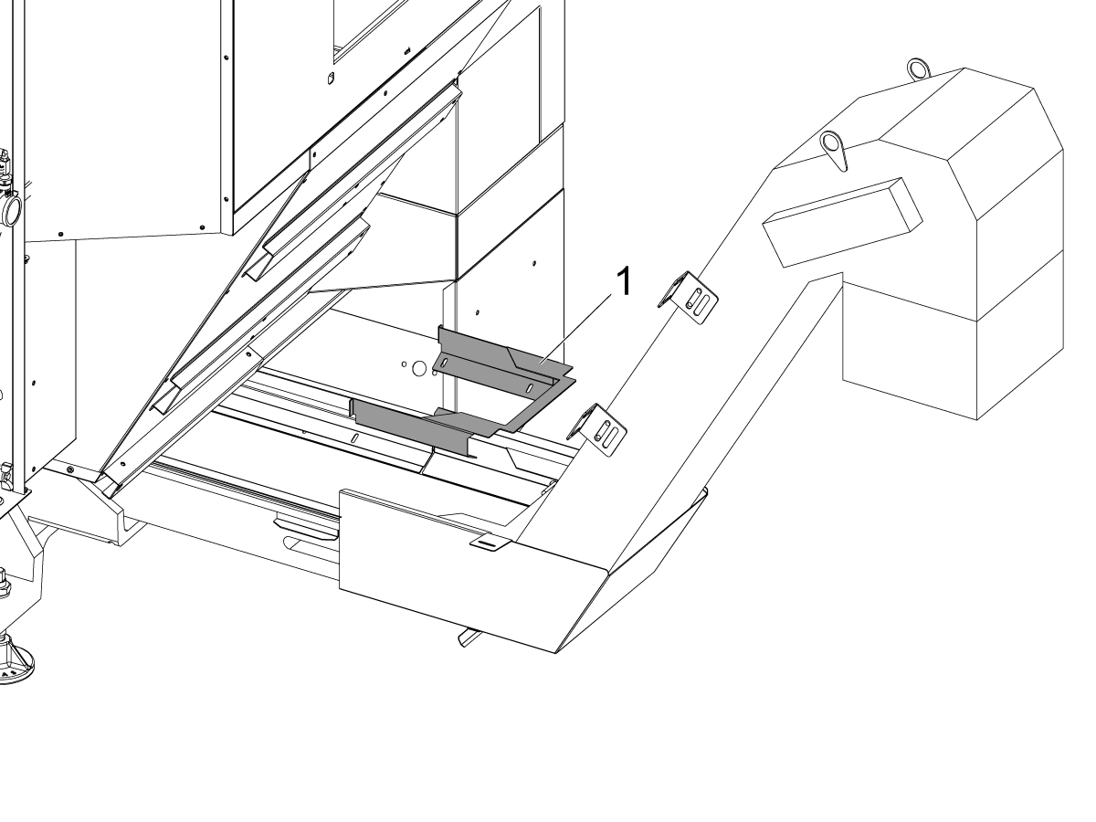
Install the trough cover [1] to the chip conveyor.

 Note: This step applies to both Hennig and Jorgensen conveyors.

Push the chip conveyor into the lathe.

Chip Conveyor - Drip Tray - Field Installation

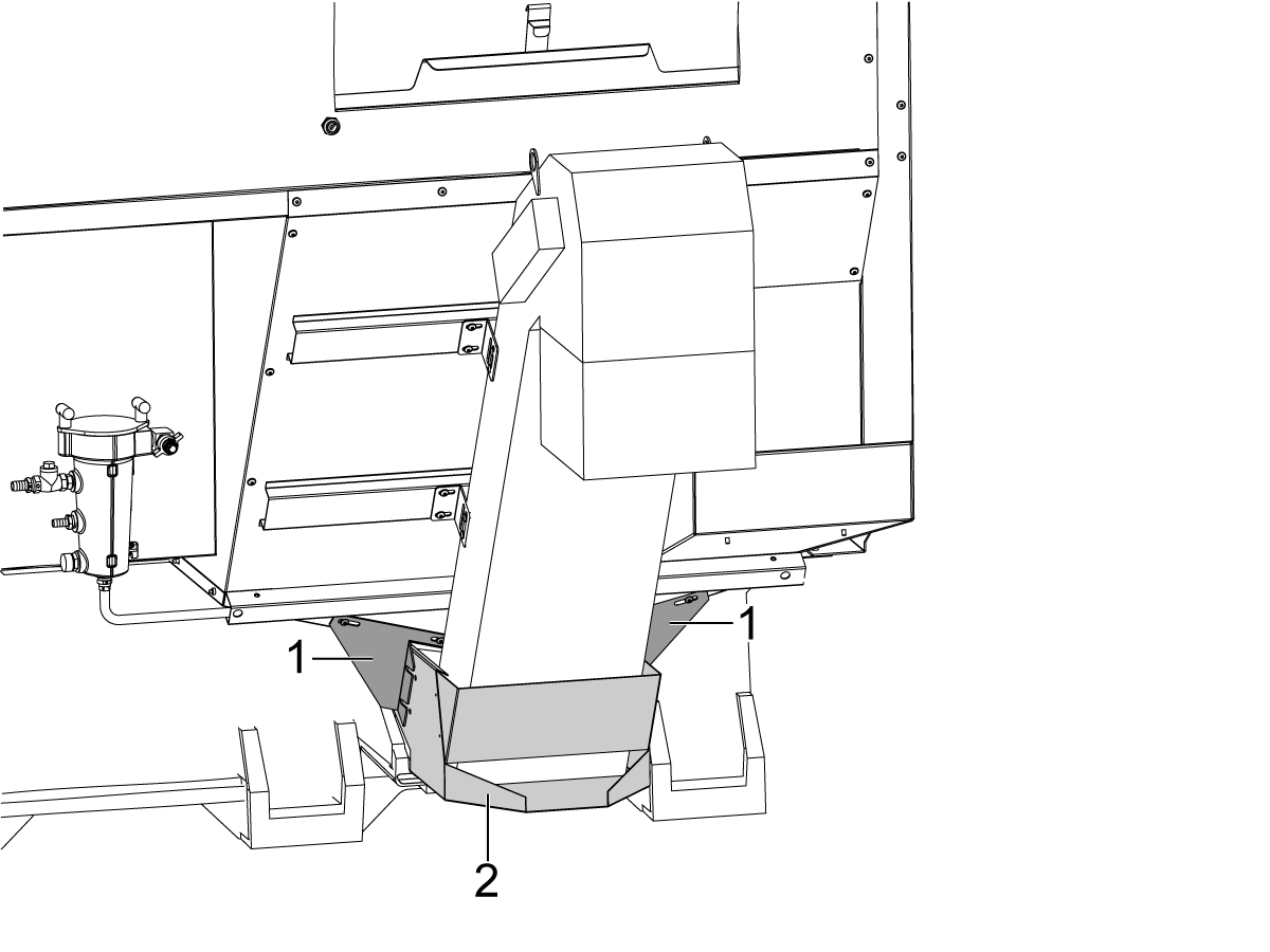
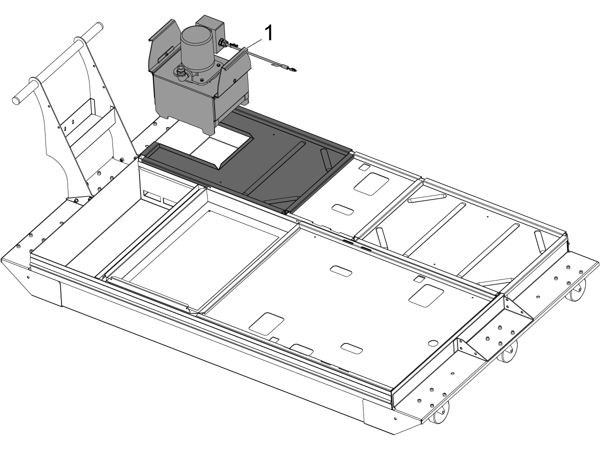
This procedure tells you how to install the chip conveyor drip tray. The chip conveyor drip tray for ST-10, ST-20, and ST-30 is packaged inside the lathe. The ST-40 drip tray is already installed.

1

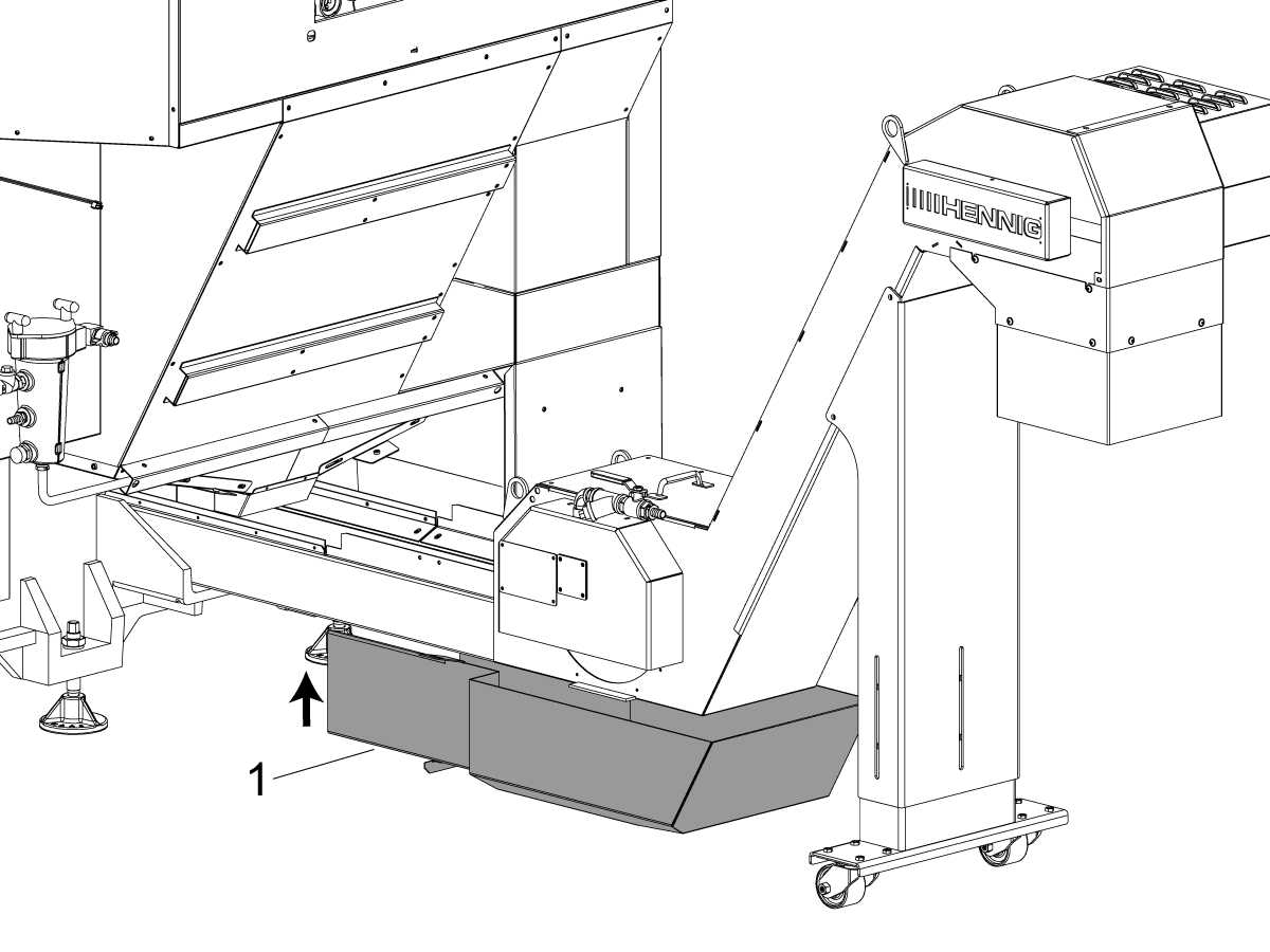
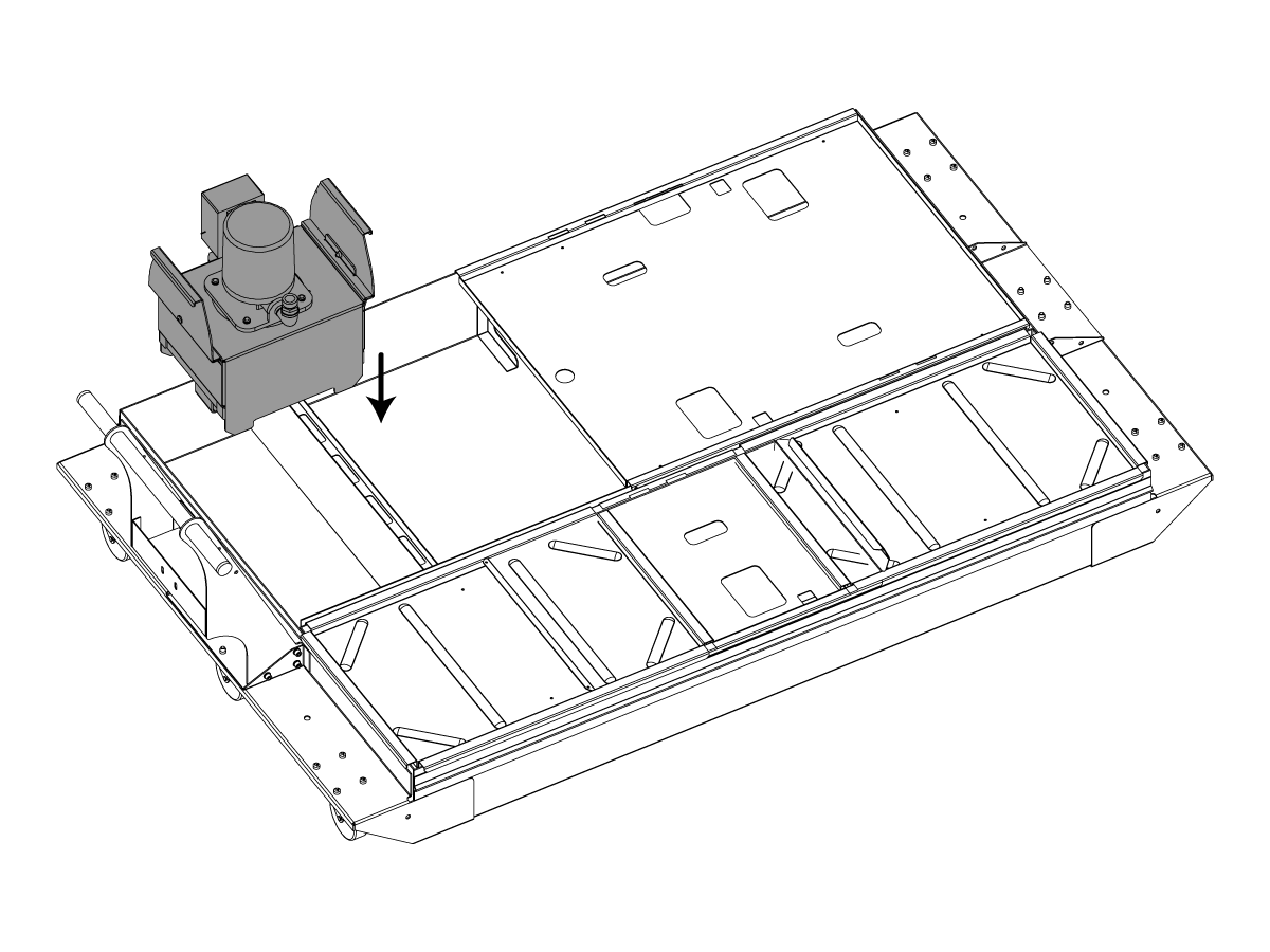
Lift the chip conveyor.

Slide the drip tray under the chip conveyor to the approximate position shown in the figure.

 Note: No fasteners are needed to keep the tray in place.

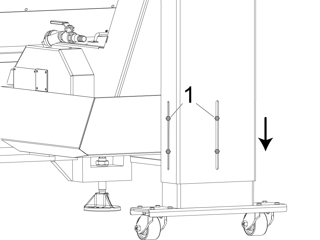
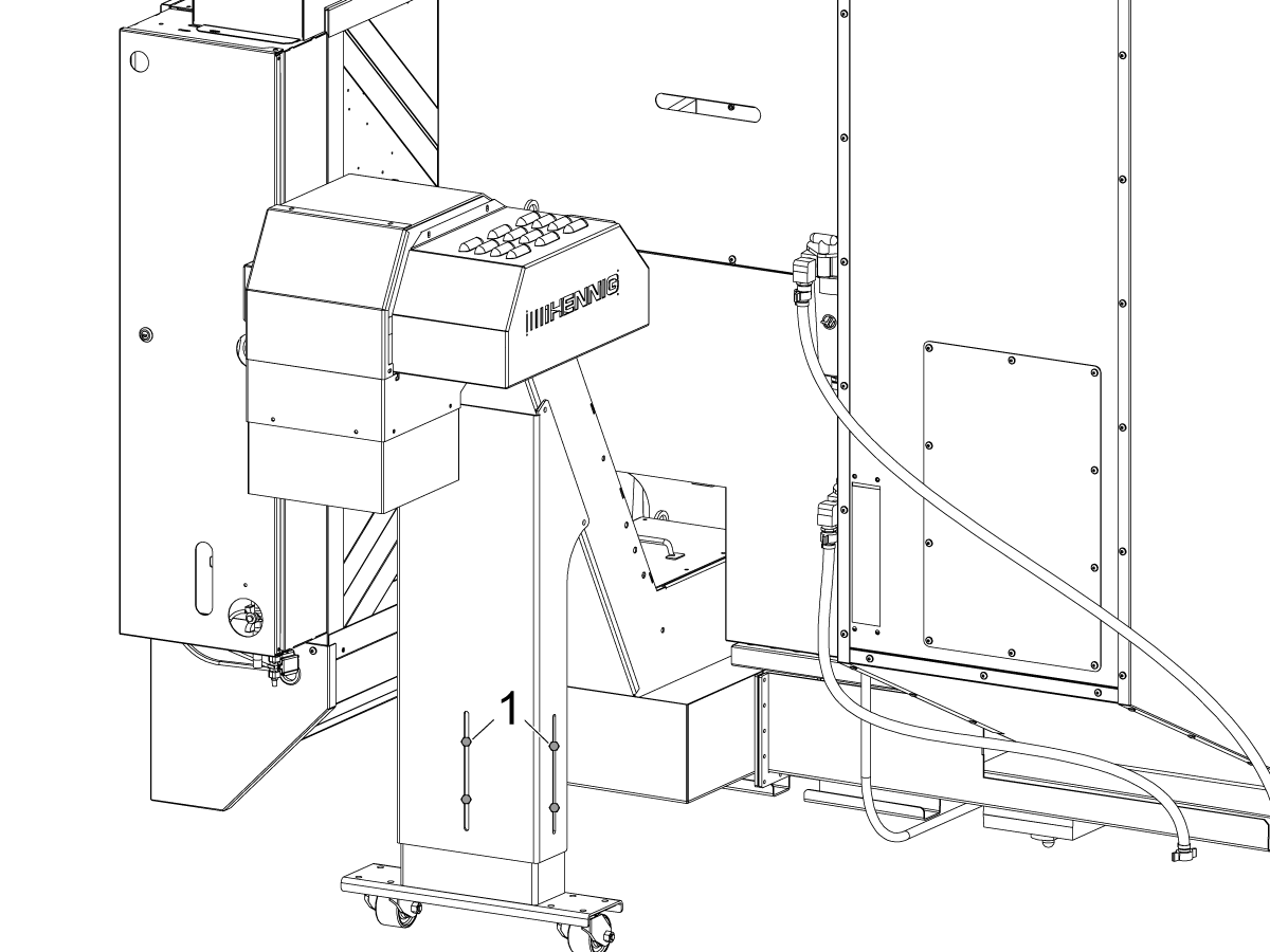
For ST-40/40L models, unfold and lock the leg before operation. The leg height needs to be adjusted so that the casters touch the floor after the machine is leveled.

Chip Conveyor - Belt Tension

1

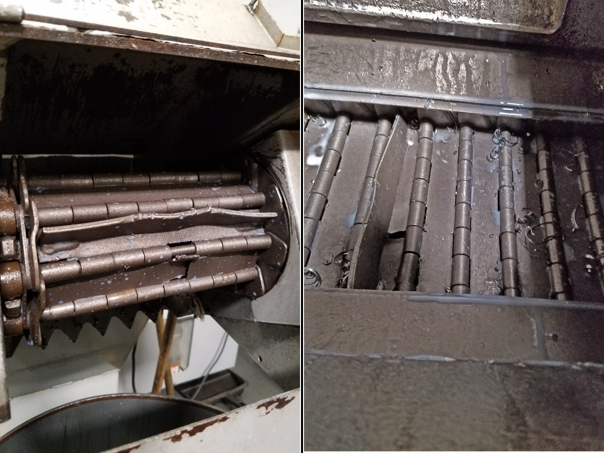
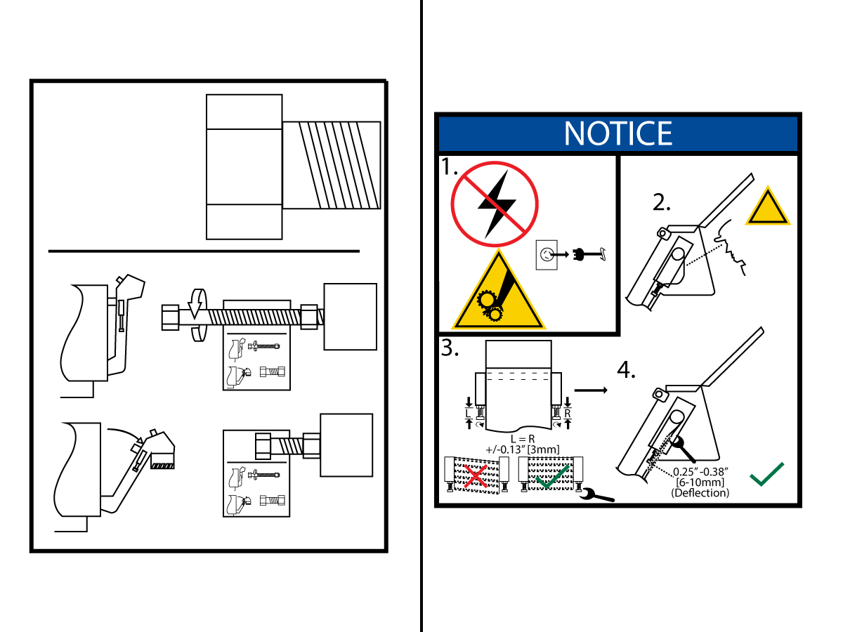
Open the cover at the head of the conveyor. Look at the belt tension as the belt goes around the sprocket.

Tighten the belt tensioning screws at either side of the conveyor head to adjust the belt drive shaft and remove slack from the belt.

 Note: Adjust the screws equally to keep the drive shaft perpendicular to belt travel.

While you adjust the belt tensioning screws, push up on the belt with a wrench at the head of the conveyor. Measure the belt slack [1] at the center of the belt in the lift section of the conveyor. The correct belt slack for Jorgensen conveyors is 0.25" - 0.38" (6 - 10 mm). The correct belt slack for Hennig conveyors is 0.12" - 0.25" (3 - 6 mm). Repeat step 2 as needed.

Apply the jam nut on each tensioning screw to lock it in place.

Install the access cover.

Chip Conveyor - Safety Skirt - Installation

1

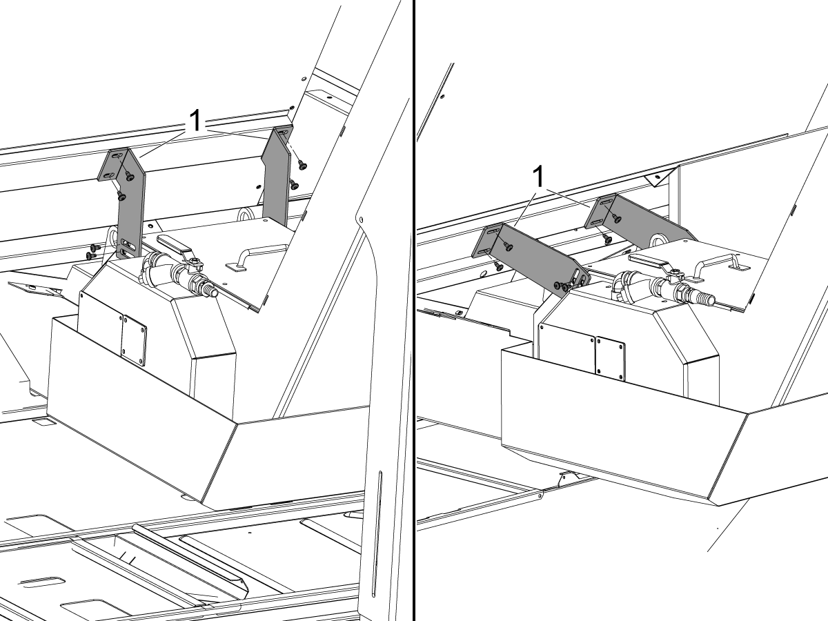
Attach the skirt [1] to the bracket [2].

Note: The seam [3] in the skirt faces the conveyor as shown.

Mount the bracket to the conveyor.

2

Connect the chip conveyor to power.

Recently Updated

TL-1/2 Chip Conveyor - Installation


AD0491

Applies to NGC machines built from: January, 2017

TL-1/2 Chip Conveyor Installation Video

Introduction

1

Field Install Kits
 
  • TL-1    93-1000484
  • TL-2    93-1000483

If the chip conveyor is a field install follow the Field Install section below.

If the machine is a new install with a chip conveyor follow the Machine Install section below.

Field Install

1

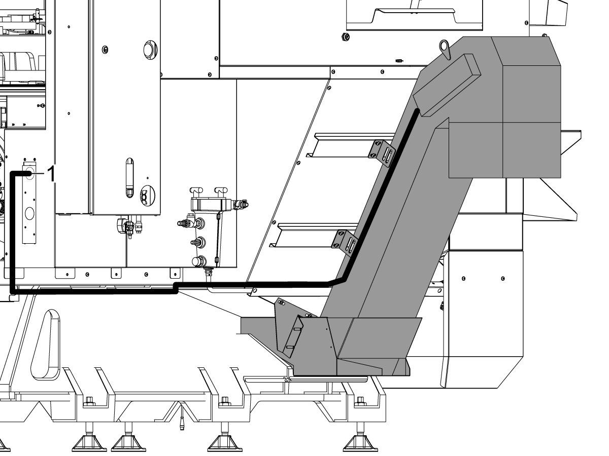
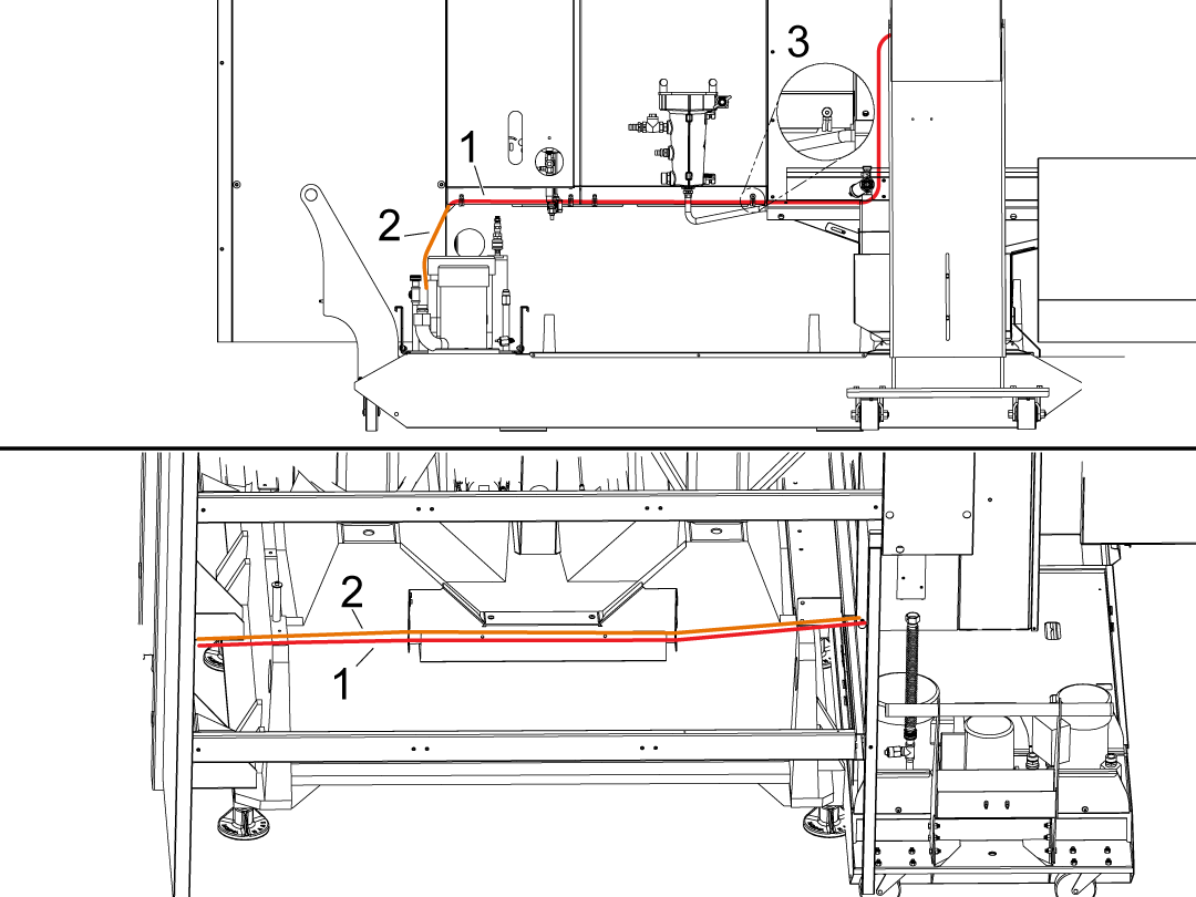
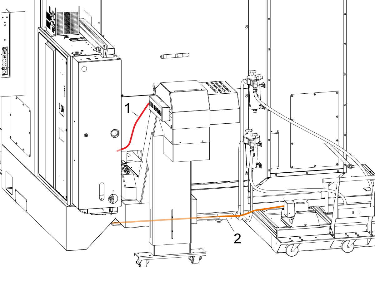
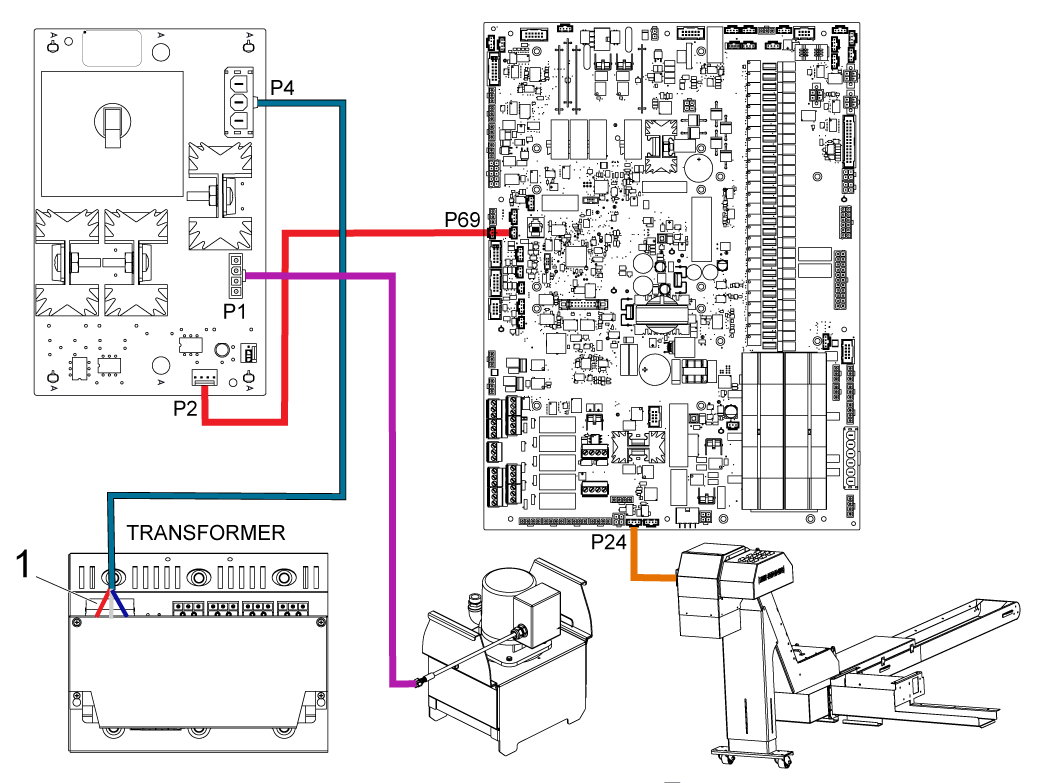
Route the chip conveyor cable from I/O P24, out the bottom of the controller and along the coolant pump cable.

Route the chip conveyor power cable from P10 on the PSUP PCB to P25 on the I/O board.

2

Install the lower bracket hardware.

Lower the chip conveyor legs and reinstall the hardware.

3

Place the chip conveyor wings on the chip conveyor belt and install the chip conveyor into the base.

Reinstall the chip conveyor wings to the chip conveyor and adjust until there is no gap between the casting and wings.

Adjust the chip conveyor legs until the chip conveyor sits flat in the base casting.

4

Open the cover at the head of the conveyor. Look at the belt tension as the belt goes around the sprocket.

Loosen the motor mount hardware and tighten the belt tensioning screws at either side of the conveyor head to adjust the belt drive shaft and remove slack from the belt.

Note: Adjust the screws equally to keep the drive shaft perpendicular to belt travel.

While you adjust the belt tensioning screws, push up on the belt with a wrench at the head of the conveyor. Measure the belt slack [1] at the center of the belt in the lift section of the conveyor. The correct belt slack for Jorgensen conveyors is 0.25" - 0.38" (6 - 10 mm). The correct belt slack for Hennig conveyors is 0.12" - 0.25" (3 - 6 mm). Repeat step 2 as needed.

Apply the jam nut on each tensioning screw to lock it in place.

Tighten the motor mount hardware.

Install the access cover.

5

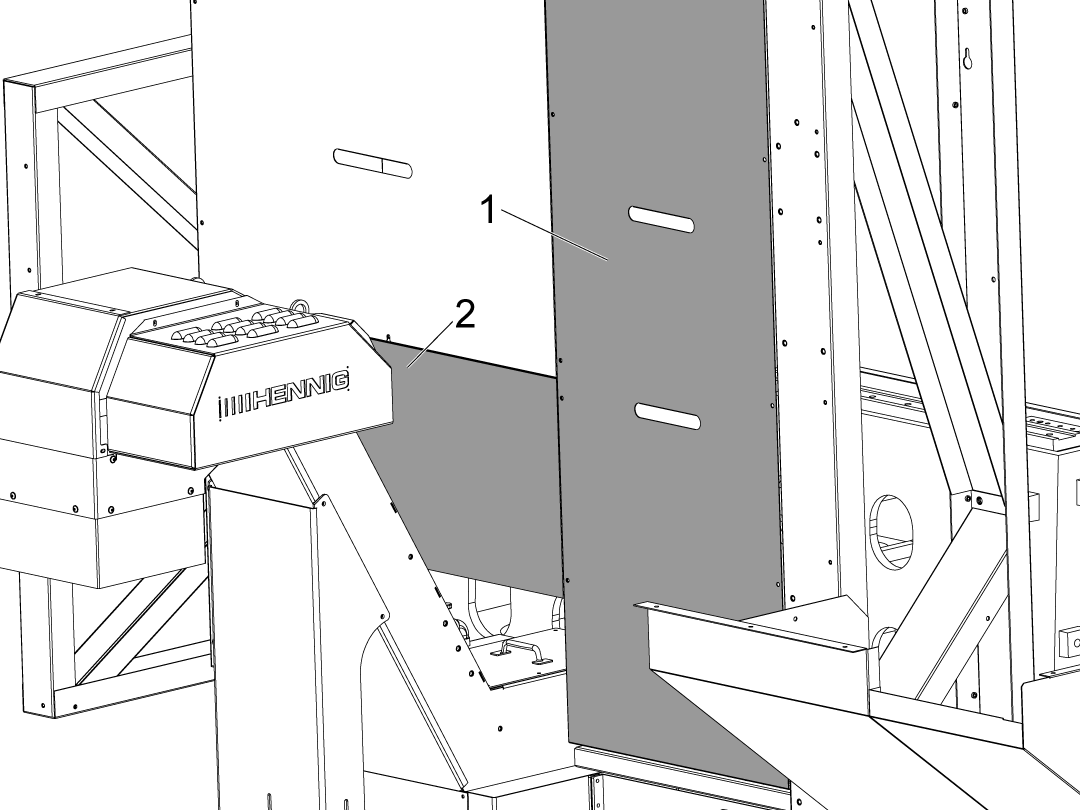
Install the chip conveyor skirt[1] to the bracket[2] and install to the chip conveyor.

Note: The seam [3] in the skirt faces the conveyor as shown.

6

Install the new coolant tank chip tray.

Plug in the chip conveyor to the plug on the controller support.

Machine Install

1

Remove the chip conveyor shipping bracket and install the tailstock stop hardware that is found inside the machine.

Install the lower bracket hardware.

Lower the chip conveyor leg to the extended position.

2

Pull the chip conveyor out of the base and place the chip conveyor wings on the chip conveyor belt.

Install the chip conveyor all the way into the base casting and reinstall the chip conveyor wings to the chip conveyor and adjust until there is no gap between the casting and wings.

Adjust the chip conveyor legs until the chip conveyor sits flat in the base casting.

3

Open the cover at the head of the conveyor. Look at the belt tension as the belt goes around the sprocket.

Loosen the motor mount hardware and tighten the belt tensioning screws at either side of the conveyor head to adjust the belt drive shaft and remove slack from the belt.

Note: Adjust the screws equally to keep the drive shaft perpendicular to belt travel.

While you adjust the belt tensioning screws, push up on the belt with a wrench at the head of the conveyor. Measure the belt slack [1] at the center of the belt in the lift section of the conveyor. The correct belt slack for Jorgensen conveyors is 0.25" - 0.38" (6 - 10 mm). The correct belt slack for Hennig conveyors is 0.12" - 0.25" (3 - 6 mm). Repeat step 2 as needed.

Apply the jam nut on each tensioning screw to lock it in place.

Tighten the motor mount hardware.

Install the access cover.

4

Install the chip conveyor skirt[1] to the bracket[2] and install to the chip conveyor.

Note: The seam [3] in the skirt faces the conveyor as shown.

Install the new coolant tank chip tray.

Plug in the chip conveyor to the plug on the controller support.

5

Install the new coolant tank chip tray.

Plug in the chip conveyor to the plug on the controller support.

Chip Conveyor Activation

Turn on the machine.

Login to the HAAS SERVICE PORTAL.

Download the Chip Conveyor option configuration patch files.

Note: The option files will appear on the configuration download page after the Chip Conveyor Kit has been ordered.  If the option does not appear contact the service department.

Load the option configuration patch file to the control.  Refer to the NEXT GENERATION CONTROL - CONFIGURATION FILE - DOWNLOAD/LOAD procedure.

Test the Chip Conveyor

1

Test the chip conveyor by pressing the [CHIP FWD],  [CHIP STOP], and [CHIP REV] buttons on the control pendant.

Recently Updated

Chip Conveyor - Motor - Replacement


AD0345

Applies to machines built from: July, 1998

Introduction

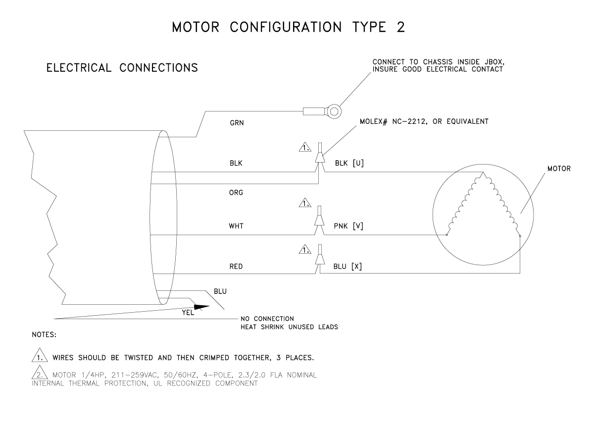
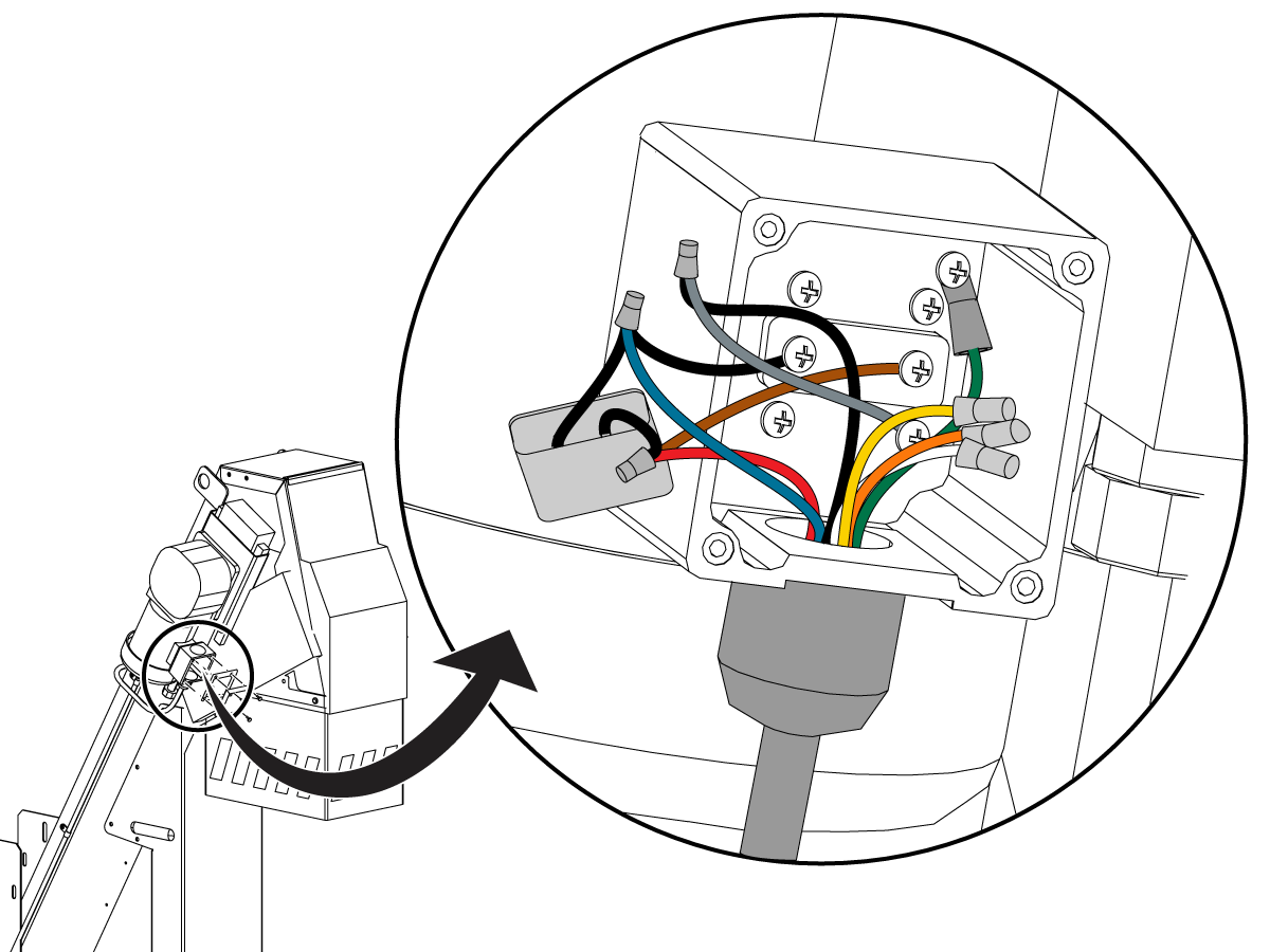
This procedure tells you how to install and wire a replacement motor for a conveyor. When you receive the replacement motor, the cable for the motor will have one of these circumstances:

  • The cable may match your existing electrical cable. In this circumstance, no modification is necessary.
  • The cable may not match your existing electrical cable. In this circumstance, you have (2) options:
    • You can bypass the extension cable on the machine and connect the new motor cable directly to the I/O PCB.
    • You can take the cable off of the old motor and install it onto the new one. This procedure shows you how to make that modification.

Use P/N 93-1224B for vertical mills and lathes. Use P/N 93-2381 for horizontal mills.

Motor Replacement

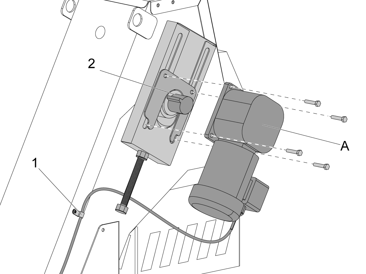
1

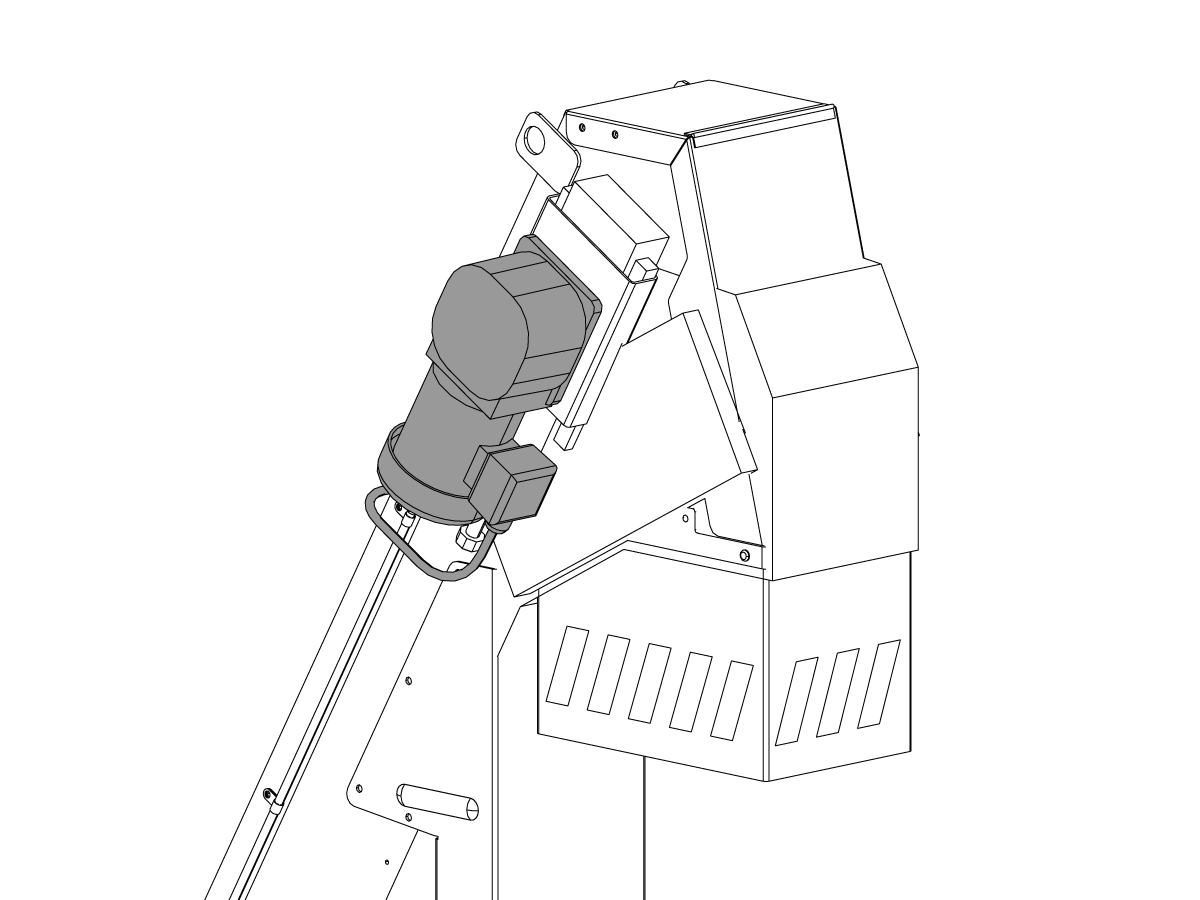
Remove the cable clamps [1].

Remove the used motor.

Press the CHIPC MOTOR 1/8HP 235V 50/60HZ [A] onto the conveyor shaft. Align the slot in the motor shaft with the key [2] on the conveyor shaft.

Attach the motor to the conveyor head.

Install the cable clamps [1].

Connect the electrical cable.

2

Do this step if you must modify the cable that came with the motor.

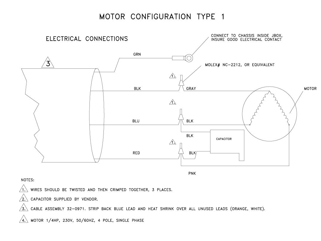
Cable Wire Connect to:  
Blue Capacitor/motor black  
Red Capacitor/motor brown  
Black Motor gray  
Green Ground  
Yellow Cap off - no connection  
Orange Cap off - no connection  
White Cap off - no connection  

Power on the machine.

Push [CHIP FWD].

If the motor is wired correctly, the chip conveyor moves forward.

Push [CHIP REV].

If the motor is wired correctly, the chip conveyor moves backward.

Recently Updated

Conveyor System - Troubleshooting Guide


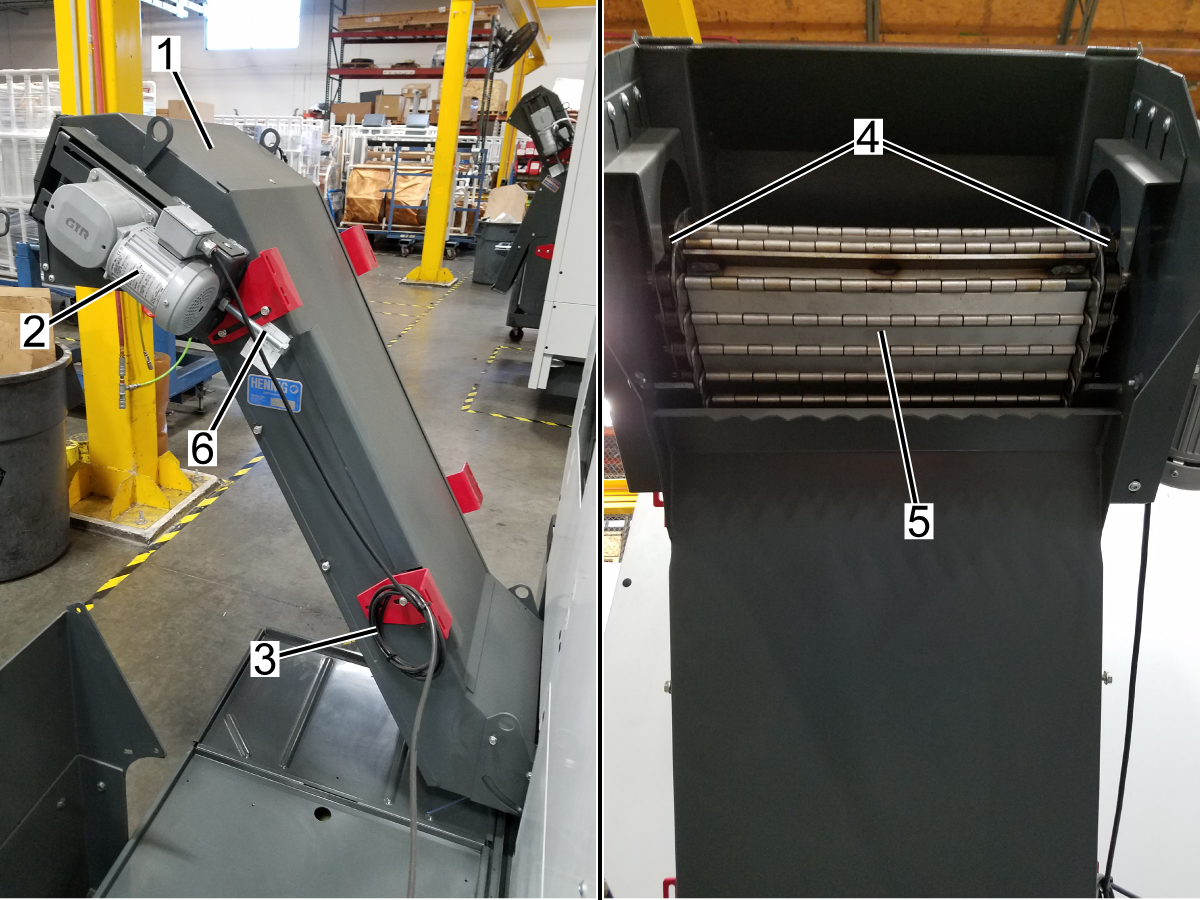
Introduction

  1. Conveyor
  2. Drive Motor
  3. Power Cord
  4. Conveyor Drive Shaft /Sprockets
  5. Belt
  6. Belt Tensioning Screws

Exploded View

  1. CONVEYOR TROUGH COVER
  2. GASKET
  3. CONVEYOR TROUGH
  4. DOUBLE CHAIN LINK OUTER
  5. SINGLE CHAIN LINK OUTER
  6. CHAIN SPACER
  7. BELT PIN
  8. CHAIN LINK INNER
  9. BELT PLATE
  10. CONVEYOR TUNNEL INSERT
  11. CONVEYOR BRACKET
  12. HHB 5/16-18 X 1
  13. CONVEYOR RAMP COVER TOP
  14. CONVEYOR RAMP COVER SIDE
  15. CONVEYOR RAMP
  16. CONVEYOR CHUTE
  17. CONVEYOR TROUGH EXTENSION
  18. BHCS 5/16-18 X 1 SS

Symptom Table

Symptom Possible Cause Corrective Action
The conveyor does not start. The circuit breaker is tripped. Check for a short in the motor or the cable.
No power from I/O PCB to the motor. Verify voltage at I/O PCB and the motor.
Blown fuses (I/O-version R and earlier). Check the fuses on the I/O PCB.
The conveyor motor capacitor is defective. Inspect motor capacitor for damage.
Conveyor is noisy or oscillates between forward and reverse. There is a build up of chips. Clear excessive chips and any obstructions.
The conveyor belt is damaged. Inspect conveyor belt and repair or replace.
The conveyor belt tension is incorrect. Adjust the belt tension.

Motor Cable Inspection

Corrective Action:

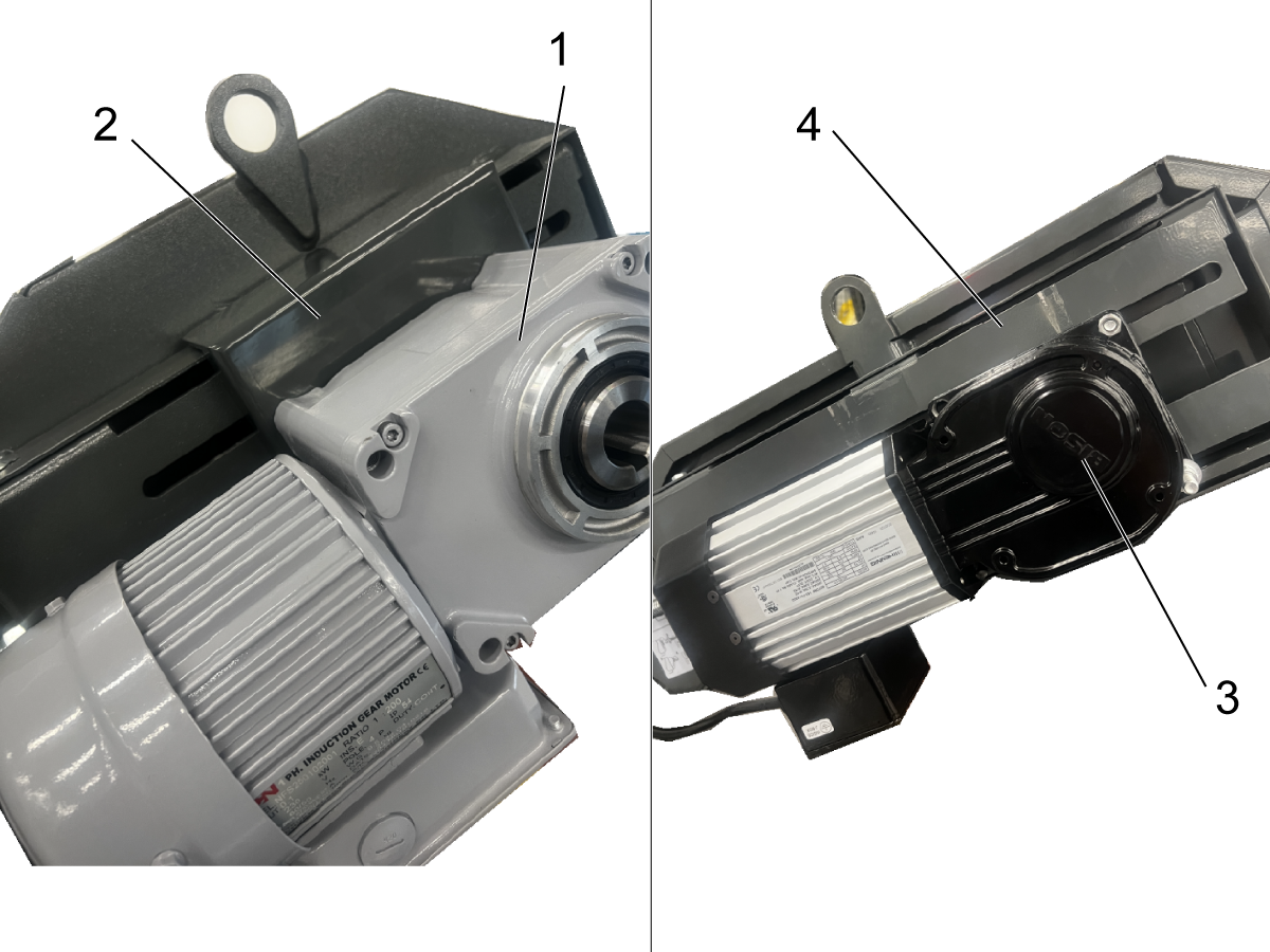
Inspect the motor cable for any sign of damage. Check for burn marks at the plug. This could be caused by coolant contamination.

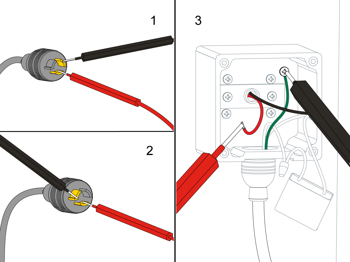
Measure the Ohms the across the motor power cable leads [1] at the plug. There should be resistance leg to leg. An open reading suggests a bad motor or cable.

Measure the Ohms on the motor power cable from each power leg to the ground leg [2] of the plug. This reading should be open.

If cable shows a short leg to ground at the plug, disconnect the power cable at the motor and check each motor power lead to the motor chassis [3]. If reading is open, the cable is at fault. If any lead tests short, the motor is motor is shorted.

Voltage

Corrective Action:

Find the chip conveyor motor cable 140 at the I/O PCB. Press [CHIP FWD]. Use a multimeter with needle tip probes to measure the voltage between the black and red wires on the cable.

Have someone press and hold [CHIP REV]. Measure the voltage between the black and white wires. When the I/O PCB operates correctly, each voltage reading is 240 VAC.

If the voltage at the I/O PCB is correct, open the conveyor motor junction box. Use a multimeter with needle tip probes to check for voltage on the power leads at the motor.

If there is no voltage, check the motor and the cable. If there is voltage, check the capacitor. If you verify the voltage and capacitor are correct, inspect the motor drive shaft and keyway.

Fuses

Corrective Action:

Check these fuses at the bottom right corner of the I/O PCB (Fuse type: AGC 5 amp):

  • Single phase motors: FU2 [1] /FU3 [2]. There should be no fuse in FU4 [3].
  • 3 phase motors: FU2 [1] /FU3 [2] /FU4 [3]

A short in the motor or the cable could have blown the fuse

Capacitor

Corrective Action:

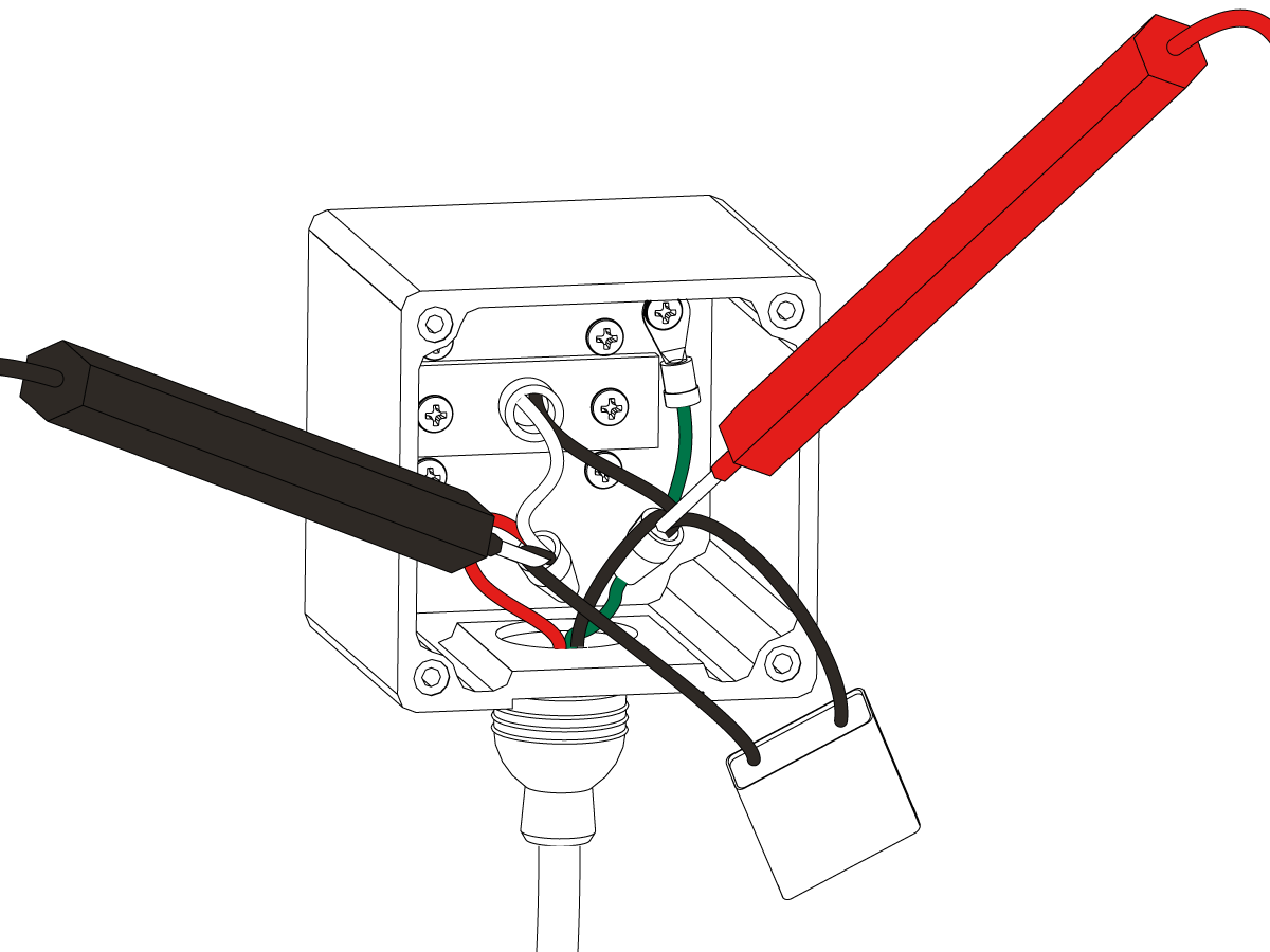
Inspect the conveyor motor capacitor for damage. A damaged capacitor will usually have signs of deformation or bubbling on the capacitor casing. This could be caused by a short in the motor or in the cable.

Open the motor junction box. Check the capacitor. Look for burn marks on the case.

Measure the capacitor. Most multimeters can measure capacitance upon manual activation (turn to the correct units of measurement, and push the yellow button). It should be 6 or 9 microfarad as noted on the capacitor's case.

Chips

Corrective Action:

Clear chips and obstructions. Make sure the conveyor settings are optimized for the chips that are produced.

Belt Inspection

Corrective Action:

Inspect the conveyor belt for damage.

Belt Tension

Corrective Action:

Make sure the belt tension is correct. Refer to the decals on the side of the machine. The correct belt slack for Jorgensen conveyors is 0.25" - 0.38" (6 - 10 mm). The correct belt slack for Hennig conveyors is 0.12" - 0.25" (3 - 6 mm). 

Electrical Diagram

FIND DISTRIBUTOR
Haas Logo

美元价格不包括关税、报关费用、保险费、增值税及运费。
USD prices DO NOT include customs duty, customs fees, insurance, VAT, or freight.

人民币价格包含关税、报关费用、货运保险和增值税, 但不包括运费。
CNY prices include customs duty, customs fees, insurance, and VAT. DOES NOT include freight.

Haas Delivered Price

This price includes shipping cost, export and import duties, insurance, and any other expenses incurred during shipping to a location in France agreed with you as a buyer. No other mandatory costs can be added to the delivery of a Haas CNC Product.

KEEP UP WITH THE LATEST HAAS TIPS AND TECHNOLOGY...

Sign up now!   

HAAS TOOLING ACCEPTS THE FOLLOWING:

  • Service & Support
  • Owners
  • Request Service
  • Operator Manuals
  • Haas Parts
  • Rotary Repair Request
  • Shopping Tools
  • Build & Price a New Haas
  • Available Inventory
  • The Haas Price List
  • CNCA Financing
  • About Haas
  • Careers
  • Certifications & Safety
  • Contact Us
  • History
  • Terms & Conditions
  • Haas Tooling Terms & Conditions
  • Privacy
  • Warranty
  • Haas Community
  • Haas Certification Program
  • Haas Motorsports
  • Gene Haas Foundation
  • HTEC Network
  • Events
  • Join the Conversation
  • Facebook
  • Twitter
  • Flickr
  • YouTube
  • LinkedIn
  • Instagram
© 2021 Haas Automation, Inc – CNC Machine Tools

2800 Sturgis Rd., Oxnard, CA 93030 / Toll Free: 800-331-6746
Phone: 805-278-1800 / Fax: 805-278-2255

Cookie Notice

We use cookies to improve your user experience. Our Cookie Notice describes which cookies we use, why we use them, and how you can find more information about them. Please confirm you consent to us using analytics cookies. If you do not consent, you may still use our website with a reduced user experience.

Manage Settings

Cookie Notice

We use cookies to improve your user experience. Our Cookie Notice describes which cookies we use, why we use them, and how you can find more information about them. Please confirm you consent to us using analytics cookies. If you do not consent, you may still use our website with a reduced user experience.

Functional Cookies

Analytics Cookies