MyHaas Velkommen,
!
Haas Tooling Gæste-bestillingshistorik MyHaas/HaasConnect Log på Tilmeld dig Haas Tooling Min konto Order History Return History MyHaas/HaasConnect Log ud Velkommen, Mine maskiner Seneste aktivitet Mine tilbud Min konto Mine brugere Log ud
Find din forhandler
  1. Vælg sprog
    1. English
    2. Deutsch
    3. Español - España
    4. Español - México
    5. Français
    6. Italiano
    7. Português
    8. Český
    9. Dansk
    10. Nederlands
    11. Magyar
    12. Polski
    13. Svenska
    14. Türkçe
    15. 中文
    16. Suomi
    17. Norsk
    18. الإنجليزية
    19. български
    20. Hrvatski
    21. Ελληνικά
    22. Română
    23. Slovenský
    24. Slovenščina
    25. 한국어
    26. 日本語
    27. Українська
  • maskiner Main Menu
    • Haas’ vertikale fræsere Vertikale fræsere
      Vertikale fræsere
      Vertikale fræsere View All
      • Vertikale fræsere
      • VF-serien
      • Universelle maskiner
      • VR-serien
      • Prismatisk VP-5
      • VMC'er med palletteveksling
      • Minifræsere
      • Formmaskiner
      • Boringscentre med høj hastighed
      • Bore-/gevindskære-/fræseserie
      • Værktøjsafdeling fræsere
      • Kompakte fræsere
      • Gantry-serie
      • SR-pladeroutere
      • Ekstra store VMC’er
      • Fræsere med dobbelt kolonne
      • Regulering af simulator
      • APL-robot til fræsere
      • VMC/UMC APL-robot med sideisætning
      • Kompakt APL-robot
    • Product Image Multi-aksede løsninger
      Multi-aksede løsninger
      Multi-aksede løsninger View All
      • Multi-aksede løsninger
      • Y-aksedrejebænke
      • 5-aksede fræsere
    • Haas-drejebænke Drejebænke
      Drejebænke
      Drejebænke View All
      • Drejebænke
      • ST-serien
      • Dobbelt spindel
      • Box Way-serien
      • Værktøjsafdelingsdrejebænke
      • Patrondrejebænk
      • Haas-stanglader V2
      • APL-robot til drejebænke
    • Haas’ horisontale fræsere Horisontale fræsere
      Horisontale fræsere
      Horisontale fræsere View All
      • Horisontale fræsere
      • Konus 50
      • Konus 40
    • Haas-rundborde og indeksere Rundborde og indekser
      Rundborde og indekser
      Rundborde og indekser View All
      • Rundborde og indekser
      • Rundborde
      • Indeksere
      • 5-aksede rundborde
      • Ekstra store rundborde
    • Product Image Automationssystemer
      Automationssystemer
      Automationssystemer View All
      • Automationssystemer
      • Automatisering af fræser
      • Drejebænksautomatisering
      • Automationsmodeller
    • Haas-boringscentre Bordmaskiner
      Bordmaskiner
      Bordmaskiner View All
      • Bordmaskiner
      • Skrivebordsfræser
      • Skrivebordsdrejebænk
    • Haas værkstedsudstyr Køb udstyr
      Køb udstyr
      Køb udstyr View All
      • Køb udstyr
      • Båndsav
      • Knæfræser
      • Overfladesliber, 2550
      • Overfladesliber, 3063
      • Laserskæremaskine
    • GENVEJE Specialserie  Specialserie 
      EU-SERIEN EU-SERIEN VERSION OG PRIS | PRISLISTE VERSION OG PRIS | PRISLISTE Maskiner på lager Maskiner på lager HVAD ER NYT? HVAD ER NYT? DIN FØRSTE CNC DIN FØRSTE CNC
      KØB AF VÆRKTØJER
      • Version og pris for en Haas
      • Prisliste
      • Tilgængeligt lager
      • CNCA-finansiering
      VIL DU TALE MED NOGEN?

      Et Haas Factory Outlet (HFO) kan besvare dine spørgsmål og guide dig gennem de bedste valgmuligheder for dig.

      CONTACT YOUR DISTRIBUTOR >
  • Ekstraudstyr Main Menu
    • Product Image Spindler
      Spindler
      Spindler View All
      • Spindler
    • Product Image Værktøjsvekslere
      Værktøjsvekslere
      Værktøjsvekslere View All
      • Værktøjsvekslere
    • Product Image 4.- | 5.-akse
      4.- | 5.-akse
      4.- | 5.-akse View All
      • 4.- | 5.-akse
    • Product Image Revolverhoveder og roterende værktøj
      Revolverhoveder og roterende værktøj
      Revolverhoveder og roterende værktøj View All
      • Revolverhoveder og roterende værktøj
    • Product Image Probing
      Probing
      Probing View All
      • Probing
    • Haas spån- og kølevandshåndtering Spån- og kølevandshåndtering
      Spån- og kølevandshåndtering
      Spån- og kølevandshåndtering View All
      • Spån- og kølevandshåndtering
    • Haas-styring Haas-styring
      Haas-styring
      Haas-styring View All
      • Haas-styring
    • Product Image Produktvalg
      Produktvalg
      Produktvalg View All
      • Produktvalg
    • Product Image Værktøjsbearbejdning og fastgørelse
      Værktøjsbearbejdning og fastgørelse
      Værktøjsbearbejdning og fastgørelse View All
      • Værktøjsbearbejdning og fastgørelse
    • Product Image Emneholder
      Emneholder
      Emneholder View All
      • Emneholder
    • Product Image 5-akse-løsninger
      5-akse-løsninger
      5-akse-løsninger View All
      • 5-akse-løsninger
      • 5 Easy Steps to 5-Axis
    • Product Image Automatisering
      Automatisering
      Automatisering View All
      • Automatisering
    • GENVEJE Specialserie  Specialserie 
      EU-SERIEN EU-SERIEN VERSION OG PRIS | PRISLISTE VERSION OG PRIS | PRISLISTE Maskiner på lager Maskiner på lager HVAD ER NYT? HVAD ER NYT? DIN FØRSTE CNC DIN FØRSTE CNC
      KØB AF VÆRKTØJER
      • Version og pris for en Haas
      • Prisliste
      • Tilgængeligt lager
      • CNCA-finansiering
      VIL DU TALE MED NOGEN?

      Et Haas Factory Outlet (HFO) kan besvare dine spørgsmål og guide dig gennem de bedste valgmuligheder for dig.

      CONTACT YOUR DISTRIBUTOR >
  • Why Haas Main Menu
      Opdag Haas-forskellen
    • Hvorfor Haas
    • MyHaas
    • Uddannelsesfællesskab
    • Industri 4.0
    • Haas-certificering
    • Kundehistorier
  • Tjeneste Main Menu
      Velkommen til Haas Service
      SERVICE HJEMME Betjeningsvejledninger Anvendelsesprocedurer Fejlfindingsguide Forebyggende vedligeholdelse Haas-reservedele Haas Tooling Videoer
  • Videoer Main Menu
×

Søgeresultater

Web Pages

Images

    • <
    • 1
    • >
MyHaas Velkommen,
!
Haas Tooling Gæste-bestillingshistorik MyHaas/HaasConnect Log på Tilmeld dig Haas Tooling Min konto Order History Return History MyHaas/HaasConnect Log ud Velkommen, Mine maskiner Seneste aktivitet Mine tilbud Min konto Mine brugere Log ud
Find din forhandler
  1. Vælg sprog
    1. English
    2. Deutsch
    3. Español - España
    4. Español - México
    5. Français
    6. Italiano
    7. Português
    8. Český
    9. Dansk
    10. Nederlands
    11. Magyar
    12. Polski
    13. Svenska
    14. Türkçe
    15. 中文
    16. Suomi
    17. Norsk
    18. الإنجليزية
    19. български
    20. Hrvatski
    21. Ελληνικά
    22. Română
    23. Slovenský
    24. Slovenščina
    25. 한국어
    26. 日本語
    27. Українська
×

Søgeresultater

Web Pages

Images

    • <
    • 1
    • >

UMC C-Axis Rotary Encoder Ring - Replacement - AD0497

Service hjemme How-to-procedure Alarmsøgning: 9918 UMC C-akse rundbord enkoderring - udskiftning - AD0497

UMC C-akse rundbord enkoderring - udskiftning - AD0497

- Gå til afsnit - Back to Top

10.2 UMC ROTARY ENCODER RING - REPLACEMENT

Recently Updated Last updated: 06/13/2025

UMC C-Axis Rotary Encoder Ring - Replacement


AD0497

Revision A 06/2025

Introduction

This procedure details the replacement of the 3" C-Axis Encoder on all UMC machines and the 3" B-Axis Encoder on UMC -500/SS machines only.

Laser calibration is required to update the compensation table for the corresponding rotary axis following the encoder replacement. 

This document applies to the following Service Kits:

  • 93-3923  ENCDR NON-CONT KIT 3"ID SER HI-RES

Used on B & C-Axis:

  • UMC-500/SS

Used on C-Axis:

  • UMC-750/SS
  • UMC-1000/SS
  • UMC-1250/SS
  • UMC-1500-DUO/SS

Tools Required:

  • 99-2130 ANTI-OXIDANT COMPOUND ELECTRICAL
  • 99-2147 DIELECTRIC GREASE PACK SUPER LUBE
  • 0.008" Mylar Shim

C-Axis Encoder Ring Replacement

1

: Warning: Only certified service personnel should perform this procedure. Reorientation of Z-pulse or Trip-Flag will require laser calibration to populate rotary compensation tables with new, correct, values.

Zero-return all Axis.

Press [EMERGENCY STOP].

2

Handle jog B to +120°.

Remove the C-Axis bottom cover.

3

Press [SETTING].

Navigate to the Rotaty tab.

Un-Check the 4th Axis.

4

Press [DIAGNOSTIC].

Navigate to Parameters > Factory.

Set 7.083 C-Axis Linear Scale Enabled to "Scale Disabled".

Power off the machine.

5

Uninstall the encoder read-head [1] by disconnecting the encoder cable [2] and removing the bolts and washers.

6

Note the Z-Pulse orientation before removing the encoder ring hub.

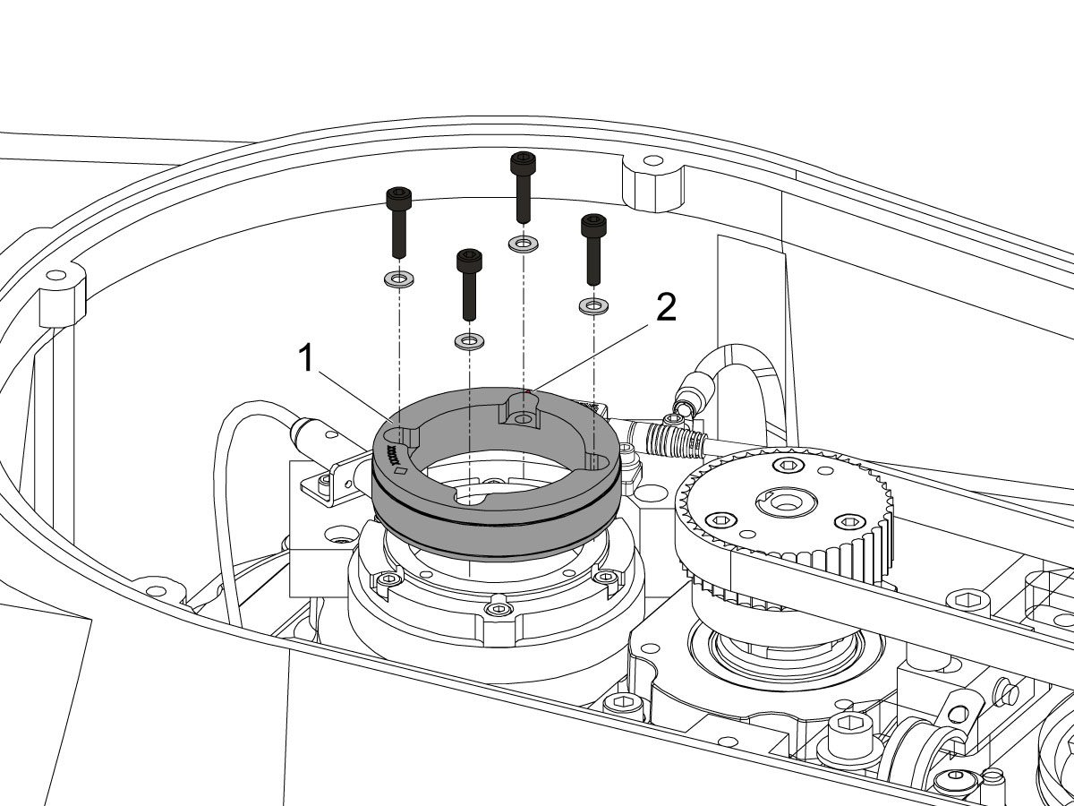
Uninstall the encoder ring hub [1] by removing the screws and washers mounting the encoder ring hub to the taper-lock. 

7

Mount and loosely install the encoder ring hub [1] from the service kit with the provided hardware, SHCS 10-32 X 3/4 (x4) and WASHER #10 FLAT (x4).

Verify the Z-Pulse is in the same location as the ring that was uninstalled. 

 Note: Do not torque mounting screws yet.

8

Turn on the machine.

Zero return all axis.

 Warning: Do not place the Mag Base anywhere near the Encoder.

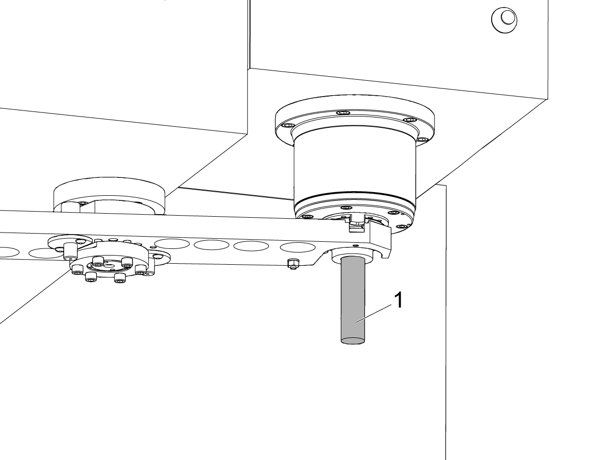
Check and document the runout on the OD of the scale encoder ring hub using the upper-most diameter, as shown.

Adjust as necessary. TIR must be 0.0005" or less.

Torque the 4 bolts of the encoder ring hub to 30 in-lbf in the star pattern.

After torquing, double check the runout to verify the ring hub has not shifted.

9

Clean the back surface of the encoder read-head and the mounting surface.

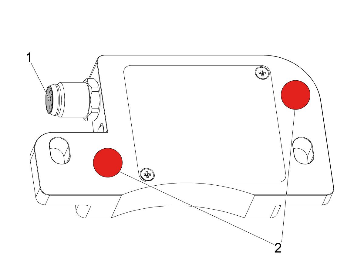
Add a small amount of silicone dielectric grease to encoder cable connection [1]. Grease should be a thin layer, but cover all the pins.

Apply two small drops of anti-oxidant (99-2130) to the mounting surface on the read head in the locations shown [2].

10

Connect the encoder cable [4] to the encoder read-head.

Insert cable by carefully lining up electrical pins with cable connector.

Install the encoder read-head [1] from the service kit with the provided hardware,  SHCS 8-32 x 1/2 bolts (x2) [2] and Washer .17ID x .4OD (2x) [3].

 Note: Do not torque mounting screws yet.

11

Set the gap between the scale ring and read-head as shown [1] using the appropriate mylar shim (0.008").

 Note: Do not use a metal shim.

Starting on the left side of the read-head [2], torque the two read-head mounting bolts to 20 in-lbf.

After torquing, double check the gap with the shim to verify the read-head has not shifted.

12

Reinstall the C-Axis bottom cover being sure no tools, shims, etc. have been left in the casting.

13

Press [SETTING].

Navigate to the Rotaty tab.

Check the 4th Axis.

Rotate the B-Axis back to zero when done.

14

Press [DIAGNOSTIC].

Navigate to Parameters > Configuration > Axis > B > Travel Limits.

Change: 6.108 B-Axis Positive Travel Limit from 180 to 110.

15

Press [DIAGNOSTIC].

Navigate to Parameters > Factory.

Set 7.083 C-Axis Linear Scale Enabled to "Scale Linear".

Power cycle the machine.

16

Zero-Return the C-Axis.

Zero-Return All Axis.

Set new Tool Change offset by following the UMC - X and Y Axes - Tool Change Offsets and the Side-Mount Tool Changer - Z-Axis Tool Change Offset - NGC procedures.

17

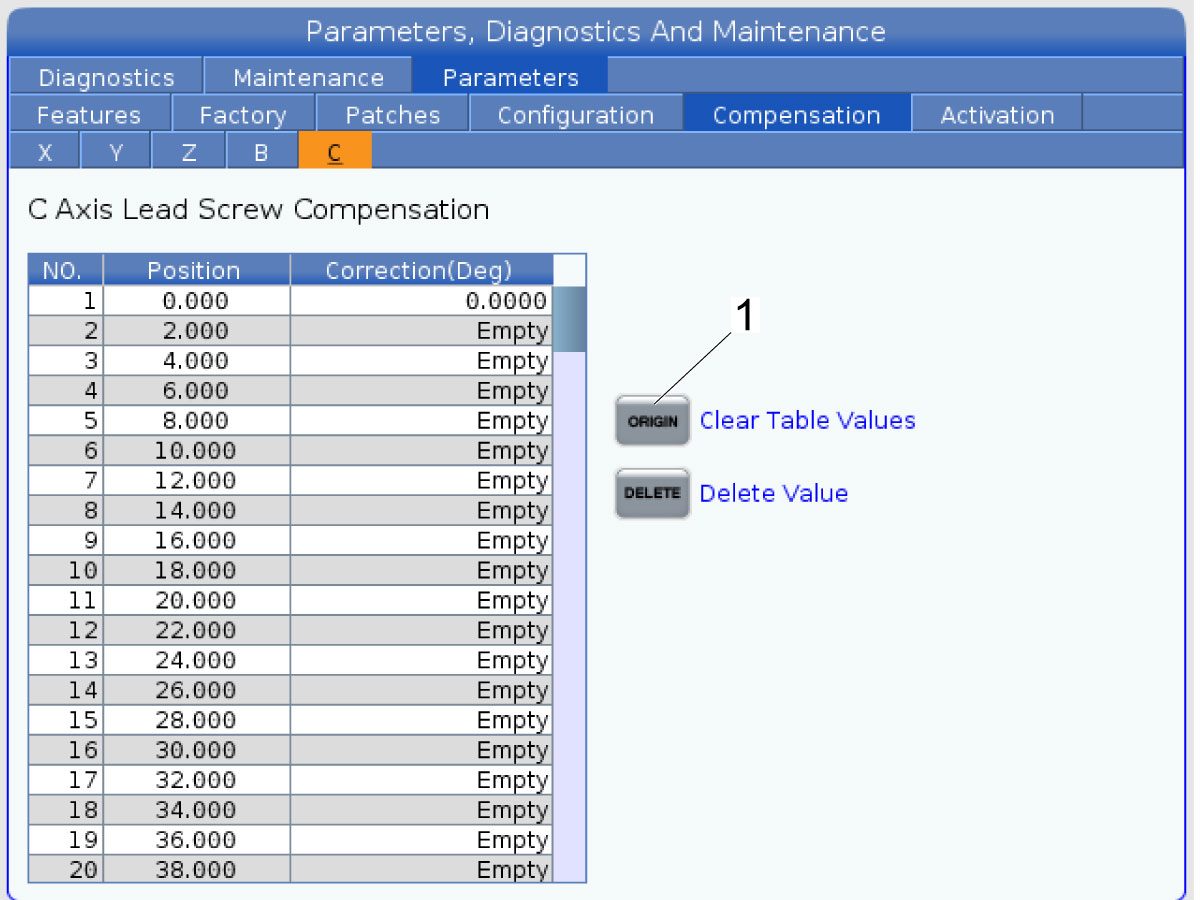
Clear the Compensation table for the C-Axis.

Press [DIAGNOSTIC].

Navigate to Parameters > Compensation > C.

Press [ORIGIN].

To update compensation table values for the C-Axis a laser calibration is required. The calculated compensation values will then be entered into the C-Axis Compensation Table.

B-Axis Encoder Ring Replacement

 Note: These step apply only to the UMC-500/SS B-Axis.

1

: Warning: Only certified service personnel should perform this procedure. Reorientation of Z-pulse or Trip-Flag will require laser calibration to populate rotary compensation tables with new, correct, values.

Zero-return all Axis.

Press [EMERGENCY STOP].

2

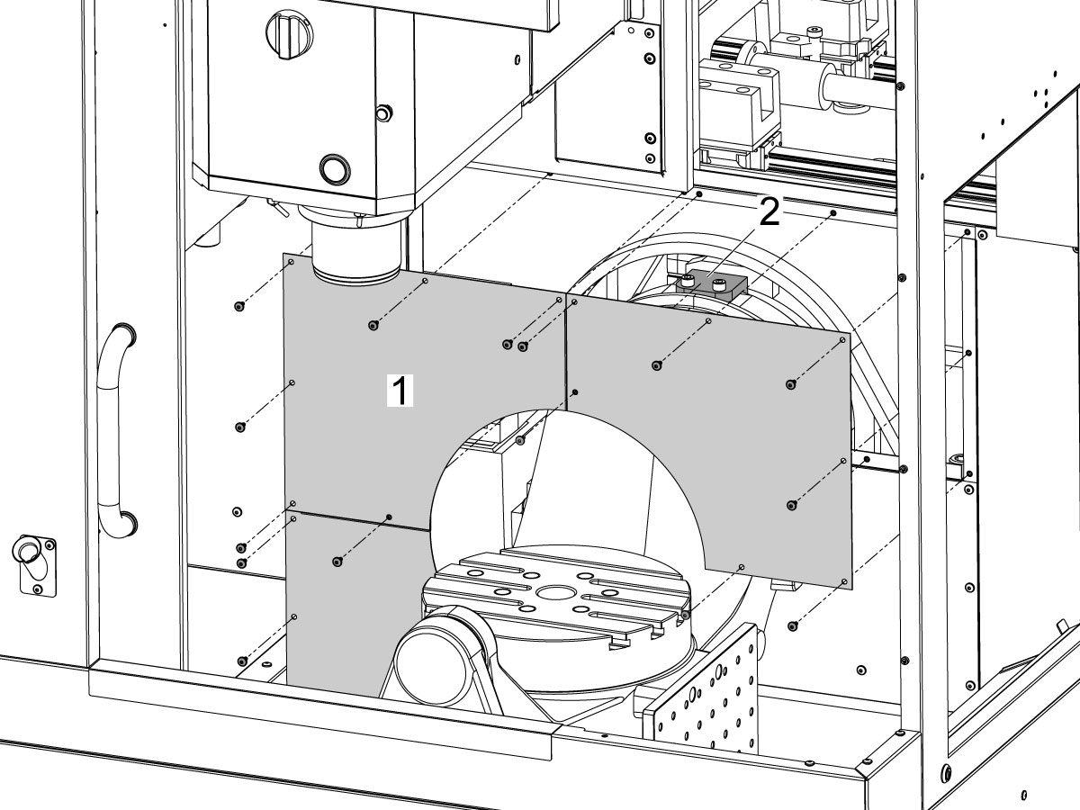
Remove the bulkhead sheet metal [1] to access the B-Axis hard stop [2]. 

3

Rotate the B-Axis approximately 100 degrees, or until there is enough room to access the hard stop [1].

Remove the B-Axis hard stop [1].

4

Remove the two rear sheet metal panels [1] to access the B-Axis components.

5

Insert a service key and enter service mode.

Press [DIAGNOSTIC].

Navigate to Parameters > Configuration > Axis > B > Travel Limits.

Change: 6.108 B-Axis Positive Travel Limit from 110 to 365.

6

Handle jog B to +180°.

Remove the C-Axis bottom cover.

7

Press [DIAGNOSTIC].

Navigate to Parameters > Factory.

Set 6.083 B-Axis Linear Scale Enabled to "Scale Disabled".

Power off the machine.

8

Disconnect all of the cables and hoses [1] running to the C-Axis through the B-Axis encoder ring. 

 Note: Mark the cables and hose to make reconnecting them easier later in this procedure. 

Remove the corrugated conduit [2].

9

Uninstall the encoder read-head [1] by disconnecting the encoder cable [2] and removing the bolts and washers.

10

Note the Z-Pulse orientation before removing the encoder ring hub.

Uninstall the encoder ring hub [1] by removing the screws and washers mounting the encoder ring hub to the taper-lock. 

11

Mount and loosely install the encoder ring hub [1] from the service kit with the provided hardware, SHCS 10-32 X 3/4 (x4) and WASHER #10 FLAT (x4).

Verify the Z-Pulse is in the same location as the ring that was uninstalled. 

 Note: If the Z-Pulse is in the wrong location the B-Axis will not zero return correctly and can damage the cables and hoses.

 Note: Do not torque mounting screws yet.

12

Route all of the cables and hoses [1] for the C-Axis through the corrugated conduit [2] and through the B-Axis encoder ring. 

Reconnect all of the cables and hoses to their original locations in the C-Axis.

13

Turn on the machine.

Zero return all axis.

 Note: The B-Axis should zero return in the Clockwise direction.

 Warning: Do not place the Mag Base anywhere near the Encoder.

Check and document the runout on the OD of the scale encoder ring hub using the upper-most diameter, as shown.

Adjust as necessary. TIR must be 0.0005" or less.

Torque the 4 bolts of the encoder ring hub to 30 in-lbf in the star pattern.

After torquing, double check the runout to verify the ring hub has not shifted.

14

Clean the back surface of the encoder read-head and the mounting surface.

Add a small amount of silicone dielectric grease to encoder cable connection [1]. Grease should be a thin layer, but cover all the pins.

Apply two small drops of anti-oxidant (99-2130) to the mounting surface on the read head in the locations shown [2].

15

Connect the encoder cable [1] to the encoder read-head.

Insert cable by carefully lining up electrical pins with cable connector.

Install the encoder read-head [2] from the service kit with the provided hardware,  SHCS 8-32 x 1/2 bolts (x2) [4] and Washer .17ID x .4OD (2x) [3].

 Note: Do not torque mounting screws yet.

16

Set the gap between the scale ring and read-head as shown [1] using the appropriate mylar shim (0.008").

 Note: Do not use a metal shim.

Starting on the left side of the read-head [2], torque the two read-head mounting bolts to 20 in-lbf.

After torquing, double check the gap with the shim to verify the read-head has not shifted.

17

Reinstall the C-Axis bottom cover being sure no tools, shims, etc. have been left in the casting.

 Note: You will have to set a new tool change offset and update compensation table values for the B-Axis. This will require laser calibration.

18

Rotate the B-Axis to the same position when the hard stop was removed. 

Install the B-Axis hard stop [1].

19

Press [DIAGNOSTIC].

Navigate to Parameters > Configuration > Axis > B > Travel Limits.

Change: 6.108 B-Axis Positive Travel Limit from 365 to 110.

Rotate the B-Axis back to zero when done.

20

Press [DIAGNOSTIC].

Navigate to Parameters > Factory.

Set 6.083 B-Axis Linear Scale Enabled to "Scale Linear".

Power cycle the machine.

21

Zero-Return the B-Axis.

Zero-Return All Axis.

Set new Tool Change offset by following the UMC - X and Y Axes - Tool Change Offsets and the Side-Mount Tool Changer - Z-Axis Tool Change Offset - NGC procedures.

22

Install the bulkhead sheet metal [1] once the B-Axis hard stop [2] has been installed. 

23

Install the two rear sheet metal panels [1].

24

Clear the Compensation table for the B-Axis.

Press [DIAGNOSTIC].

Navigate to Parameters > Compensation > B.

Press [ORIGIN].

To update compensation table values for the B-Axis a laser calibration is required. The calculated compensation values will then be entered into the B-Axis Compensation Table.

Recently Viewed Items

You Have No Recently Viewed Items Yet

Feedback
Haas Logo

美元价格不包括关税、报关费用、保险费、增值税及运费。
USD prices DO NOT include customs duty, customs fees, insurance, VAT, or freight.

人民币价格包含关税、报关费用、货运保险和增值税, 但不包括运费。
CNY prices include customs duty, customs fees, insurance, and VAT. DOES NOT include freight.

Haas-leveret pris

Denne pris omfatter forsendelsesomkostninger, eksport- og importafgifter og alle andre udgifter i forbindelse med levering til en lokation i Frankrig, der er aftalt med dig som køber. Ingen andre obligatoriske omkostninger kan blive tilføjet leveringen af et Haas CNC-produkt.

HOLD DIG OPDATERET MED DE SENESTE HAAS-TIPS OG TEKNOLOGI ...

Tilmeld dig nu!   

HAAS TOOLING ACCEPTS THE FOLLOWING:

  • Service og Support
  • Ejere
  • Anmod om service
  • Betjeningsvejledninger
  • Haas-reservedele
  • Anmodning om reparation af rundbord
  • Anbefalinger inden du installerer
  • Køb af værktøjer
  • Version og pris for en ny Haas
  • Tilgængeligt lager
  • Haas-prisliste
  • CNCA-finansiering
  • Om Haas
  • DNSH-erklæring
  • Karriere
  • Certificeringer og sikkerhed
  • Kontakt os
  • Oversigt
  • Vilkår og betingelser
  • Haas Tooling: vilkår og betingelser
  • Databeskyttelse
  • Garanti
  • Haas-fællesskab
  • Haas CNC-certificeringsprogram
  • Haas Motorsports
  • Gene Haas Foundation
  • Haas teknisk træningsfællesskab
  • Events
  • Deltag i samtalen
  • Facebook
  • X
  • Flickr
  • YouTube
  • LinkedIn
  • Instagram
  • TikTok
© 2025 Haas Automation, Inc – CNC-maskiner

This site is protected by reCAPTCHA and the Google Privacy Policy and Terms of Service apply.

2800 Sturgis Rd., Oxnard, CA 93030 / Toll Free: 800-331-6746
Phone: 805-278-1800 / Fax: 805-278-2255