MyHaas Bem-vindo,
!
Haas Tooling Histórico de encomendas do convidado MyHaas/HaasConnect Iniciar a sessão Registar Haas Tooling A minha conta Order History Return History MyHaas/HaasConnect Encerrar a sessão Bem-vindo, As minhas máquinas Última atividade Os meus orçamentos A minha conta Os meus utilizadores Encerrar a sessão
Encontrar o seu distribuidor
  1. Selecionar idioma
    1. English
    2. Deutsch
    3. Español - España
    4. Español - México
    5. Français
    6. Italiano
    7. Português
    8. Český
    9. Dansk
    10. Nederlands
    11. Magyar
    12. Polski
    13. Svenska
    14. Türkçe
    15. 中文
    16. Suomi
    17. Norsk
    18. الإنجليزية
    19. български
    20. Hrvatski
    21. Ελληνικά
    22. Română
    23. Slovenský
    24. Slovenščina
    25. 한국어
    26. 日本語
    27. Українська
  • máquinas Main Menu
    • Fresadoras Verticais Haas Fresadoras verticais
      Fresadoras verticais
      Fresadoras verticais View All
      • Fresadoras verticais
      • Série VF
      • Máquinas universais
      • Série VR
      • VP-5 prismático
      • VMC com troca de paletes
      • Mini fresadoras
      • Máquinas de moldagem
      • Centros de perfuração de alta velocidade
      • Série Perfurar/Roscar/Fresar
      • Fresadora Sala de Ferramentas
      • Fresadoras compactas
      • Série pórtico
      • Routers de chapa SR
      • VMC extragrande
      • Fresadoras de coluna dupla
      • Simulador de controlo
      • Fresadora com carregador de peças automático
      • Carregador de peças automático de carga lateral VMC/UMC
      • Carregador de peças automático compacto
    • Product Image Soluções multi-eixo
      Soluções multi-eixo
      Soluções multi-eixo View All
      • Soluções multi-eixo
      • Tornos de eixo Y
      • Fresadoras de 5 eixos
    • Tornos Haas Tornos
      Tornos
      Tornos View All
      • Tornos
      • Série ST
      • Spindle duplo
      • Série Box Way
      • Tornos de sala de ferramentas
      • Torno de Bucha
      • Alimentação de barra Haas V2
      • Torno com carregador de peças automático
    • Fresadoras horizontais Haas Fresadoras horizontais
      Fresadoras horizontais
      Fresadoras horizontais View All
      • Fresadoras horizontais
      • Cone ISO50
      • Cone ISO40
    • Produtos rotativos e indexadores Haas Rotativos e Indexadores
      Rotativos e Indexadores
      Rotativos e Indexadores View All
      • Rotativos e Indexadores
      • Mesas rotativas
      • Indexadores
      • Rotativos de 5 eixos
      • Rotativos extra-grandes
    • Product Image Sistemas de automatização
      Sistemas de automatização
      Sistemas de automatização View All
      • Sistemas de automatização
      • Automatização de fresadora
      • Automatização de tornos
      • Modelos de automatização
    • Centros de perfuração Haas Máquinas Desktop
      Máquinas Desktop
      Máquinas Desktop View All
      • Máquinas Desktop
      • Fresadora Desktop
      • Torno Desktop
    • Equipamento de oficina Haas Comprar equipamento
      Comprar equipamento
      Comprar equipamento View All
      • Comprar equipamento
      • Serra
      • Fresadora de joelho
      • Esmeril de superfície, 2550
      • Esmeril de superfície, 3063
      • Máquina de corte a laser
    • LIGAÇÕES RÁPIDAS Série especial  Série especial 
      SÉRIE UE SÉRIE UE CONSTRUÇÃO E PREÇO | LISTA DE PREÇOS CONSTRUÇÃO E PREÇO | LISTA DE PREÇOS Máquinas em stock Máquinas em stock NOVIDADES NOVIDADES A SUA PRIMEIRA CNC A SUA PRIMEIRA CNC
      FERRAMENTAS DE COMPRAS
      • Construção e Preço de uma Haas
      • Lista de Preços
      • Inventário disponível
      • Financiamento CNCA
      QUER FALAR COM ALGUÉM?

      A Haas Factory Outlet (HFO) pode responder às suas perguntas e orientá-lo nas suas melhores opções.

      CONTACT YOUR DISTRIBUTOR >
  • Opções Main Menu
    • Product Image Spindles
      Spindles
      Spindles View All
      • Spindles
    • Product Image Trocadores da ferramenta
      Trocadores da ferramenta
      Trocadores da ferramenta View All
      • Trocadores da ferramenta
    • Product Image 4.º | 5.º eixo
      4.º | 5.º eixo
      4.º | 5.º eixo View All
      • 4.º | 5.º eixo
    • Product Image Torretas e ferramenta motorizada
      Torretas e ferramenta motorizada
      Torretas e ferramenta motorizada View All
      • Torretas e ferramenta motorizada
    • Product Image Sondagem
      Sondagem
      Sondagem View All
      • Sondagem
    • Gestão de limalha e líquido de refrigeração Haas Gestão da limalha e do líquido de refrigeração
      Gestão da limalha e do líquido de refrigeração
      Gestão da limalha e do líquido de refrigeração View All
      • Gestão da limalha e do líquido de refrigeração
    • O controlador Haas O controlador Haas
      O controlador Haas
      O controlador Haas View All
      • O controlador Haas
    • Product Image Opções de Produtos
      Opções de Produtos
      Opções de Produtos View All
      • Opções de Produtos
    • Product Image Ferramentas e Fixação
      Ferramentas e Fixação
      Ferramentas e Fixação View All
      • Ferramentas e Fixação
    • Product Image Dispositivo de aperto
      Dispositivo de aperto
      Dispositivo de aperto View All
      • Dispositivo de aperto
    • View All
    • Product Image Soluções de 5 eixos
      Soluções de 5 eixos
      Soluções de 5 eixos View All
      • Soluções de 5 eixos
      • 5 Easy Steps to 5-Axis
    • Product Image AUTOMATIZAÇÃO
      AUTOMATIZAÇÃO
      AUTOMATIZAÇÃO View All
      • AUTOMATIZAÇÃO
    • LIGAÇÕES RÁPIDAS Série especial  Série especial 
      SÉRIE UE SÉRIE UE CONSTRUÇÃO E PREÇO | LISTA DE PREÇOS CONSTRUÇÃO E PREÇO | LISTA DE PREÇOS Máquinas em stock Máquinas em stock NOVIDADES NOVIDADES A SUA PRIMEIRA CNC A SUA PRIMEIRA CNC
      FERRAMENTAS DE COMPRAS
      • Construção e Preço de uma Haas
      • Lista de Preços
      • Inventário disponível
      • Financiamento CNCA
      QUER FALAR COM ALGUÉM?

      A Haas Factory Outlet (HFO) pode responder às suas perguntas e orientá-lo nas suas melhores opções.

      CONTACT YOUR DISTRIBUTOR >
  • Why Haas Main Menu
      Descubra a Diferença da Haas
    • Porquê a Haas?
    • MyHaas
    • Comunidade de formação
    • Indústria 4.0
    • Certificação Haas
    • Testemunhos de clientes
  • Assistência Main Menu
      Bem-vindo à Haas Service
      INÍCIO DA ASSISTÊNCIA Manuais do operador Procedimentos como fazer Manuais de Resolução de Problemas Manutenção preventiva Peças Haas Haas Tooling Vídeos
  • Vídeos Main Menu
×

Resultados da pesquisa

Web Pages

Images

    • <
    • 1
    • >
MyHaas Bem-vindo,
!
Haas Tooling Histórico de encomendas do convidado MyHaas/HaasConnect Iniciar a sessão Registar Haas Tooling A minha conta Order History Return History MyHaas/HaasConnect Encerrar a sessão Bem-vindo, As minhas máquinas Última atividade Os meus orçamentos A minha conta Os meus utilizadores Encerrar a sessão
Encontrar o seu distribuidor
  1. Selecionar idioma
    1. English
    2. Deutsch
    3. Español - España
    4. Español - México
    5. Français
    6. Italiano
    7. Português
    8. Český
    9. Dansk
    10. Nederlands
    11. Magyar
    12. Polski
    13. Svenska
    14. Türkçe
    15. 中文
    16. Suomi
    17. Norsk
    18. الإنجليزية
    19. български
    20. Hrvatski
    21. Ελληνικά
    22. Română
    23. Slovenský
    24. Slovenščina
    25. 한국어
    26. 日本語
    27. Українська
×

Resultados da pesquisa

Web Pages

Images

    • <
    • 1
    • >

Rotary - Troubleshooting Guide - NGC

Início da Assistência Pesquisa de alarme: 5.4011 Rotativa - Guia de resolução de problemas - NGC

Rotativa - Guia de resolução de problemas - NGC

- Ir para causa - Back to Top

8.1 Rotary - Troubleshooting - NGC

Recently Updated Last updated: 04/25/2025

Rotary - Troubleshooting Guide - NGC


Revision A - 4/2025

Symptom Table

Do not perform any type of maintenance on the rotarty if it is under warranty, contact your Haas Factory Outlet for further assistance.

Download and fill out the Rotary Inspection Report Checklist below before replacing any parts.

Rotary Inspection Report Checklist
Symptom Possible Cause Corrective Action
Alarm 5.108, 6.108 or 7.108 A, B or C AXIS SERVO OVERLOAD The feeds and speeds are too high for the work.  Decrease the feeds and speeds. 
The cutting tool is not sharp or is damaged.  Install a new device or a new tool insert. 
There is a mechanical blockage in the axis of travel.  Make sure the axis has a clear path of travel. 
There is an internal mechanical obstruction in the rotary unit.  Test the rotary unit. 
The brake solenoid for the rotary unit has an electrical fault.  Troubleshoot the brake solenoid. 
The servo amplifier has a problem Troubleshoot the servo amplifier. 
Alarm 5.103, 6.103, 7.103 A, B or C AXIS SERVO ERROR TOO LARGE The air brake did not disengage.  Remove the air from the rotary and see if the unit will rotate without an alarm.  
The connection to the encoder or power is faulty.  Check the encoder and power cable connections to the motor. 
The machined part has inaccurate features.  There is lost motion or backlash in the rotary.  Do the rotary backlash test. 
The feeds and speeds are too high for the work.  Decrease the feeds and speeds. 
The trunnion's tilt (A) axis does not find a home.
The home sensor or cable is faulty. 

Jog the tilt axis from the positive travel limit to the negative travel limit. Make sure the A HOME SWITCH bit changes (on the Diagnostics INPUT 2 screen). If the bit does not change, replace the home switch.

This can be done in the field. This cannot be done on TR110 units.

Note: The A HOME SWITCH change cannot be seen on machines with software version 18.16A or higher.

Caution: If the A axis (tilt) moves more than 20 degrees past the home position,

Push [EMERGENCY STOP]

The tilt (A) axis does not home to a horizontal position.
The tool change offset parameter has not been set.  Set the rotary platter flatness: Refer to the Rotary - TR/TRT/T5C - Platter Flatness - Adjustment procedure.
Starting in software version 100.19.000.1120 when using P11, P12, and P13 parameters for T5C/Trunnions. There is an excessive rotation when the unit is commanded to zero return.    The parameter *.161 AXIS HOME SWITCH ACTIVE HIGH is incorrectly set to TRUE. Go to the Haas Service Portal and download the latest configuration files.  Update the rotary configuration files refer to the Update Rotary Configuration Files - NGC procedure. 

Alarm 5.423, 6.423 or 7.423 A, B or C AXIS SECONDARY ENCODER POSITION MISMATCH

Alarm 5.9944, 6.9944 or 7.9944 A, B or C AXIS SECONDARY ENCODER Z FAULT

Alarm 5.9945, 6.9945 or 7.9945 A, B or C AXIS SECONDARY ENCODER Z CHANNEL MISSING

Alarm 5.9946, 6.9946 or 7.9946 A, B or C AXIS SECONDARY ENCODER CABLE FAULT


The rotary scale or scale cable is faulty.  Check the rotary scale cable. 

Alarm 175 GROUND FAULT DETECTED

Alarm 552 TRIPPED CIRCUIT BREAKER


There is a short to ground in the axis motor cable.  Test the axis motor cable for short. 
There is a short to ground in the axis motor.  Test the axis motor for short.
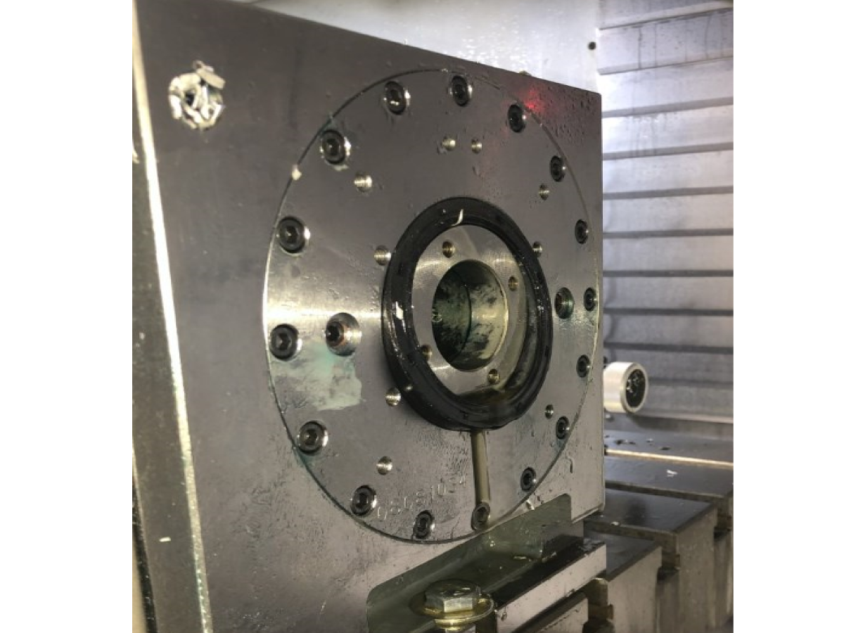
HRC rear seal is popping out.  The oil level is too high.  Drain oil until the correct level is reached; use sight glass to identify if oil is filled to the top of the glass. 
Internal pressure is unable to escape 

NOTE: ONLY DO THIS ONCE THE OIL LEVEL HAS BEEN VERIFIED, AND THE SEAL CONTINUES TO POP OUT.

Replace two of the break fasteners with modified fasteners. See "Rear seal popping out" section below for further instructions. 

Alarm 5.9918, 6.9918 or 7.9918 A, B or C AXIS SERIAL ENCODER INTERNAL DATA ERROR

Alarm 5.9922, 6.9922 or 7.9922 A, B or C AXIS MOTION CHANNEL FAULT DETECTED

Alarm 5.9923, 6.9923 or 7.9923 A, B or C AXIS SOFTWARE DETECTED ENCODER FAULT

Alarm 5.9930, 6.9930 or 7.9930 A, B or C AXIS SERIAL ENCODER POOR COMMUNICATION

Alarm 5.9959, 6.9959 or 7.9959 A, B or C AXIS SERIAL ENCODER DISCONNECT

Alarm 5.9948, 6.9948 or 7.9948 A, B or C AXIS SECONDARY ENCODER SERIAL FAULT

Alarm 5.9949, 6.9949 or 7.9949 A, B or C AXIS SOFTWARE DETECTED SECONDARY ENCODER FAULT

Alarm 5.9950, 6.9950 or 7.9950 A, B or C AXIS SOFTWARE DETECTED SECONDARY ENCODER FAULT

Alarm 5.9951, 6.9951 or 7.9951 A, B or C AXIS SECONDARY ENCODER SERIAL COMMUNICATION FAULT

Alarm 5.9960, 6.9960 or 7.9960 A, B or C AXIS SECONDARY SERIAL ENCODER CABLE FAULT


The  software is outdated. 

Alarm is obsolete 

New alarm for encoder faults updated in software. Update to latest version 100.21.000.1130 or Higher;

Added Alarms 9719 and 9720 for Encoder Fault Detection on Mocon Primary and Secondary Axis.

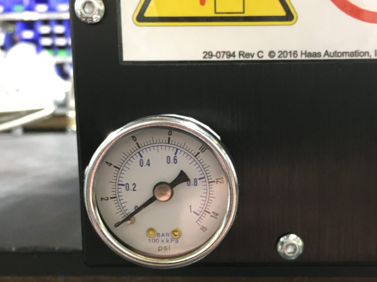
Air leak/hissing sound coming from the motor enclosure. Motor enclosure ballooning out. Excessive bubbles are leaking between the side plate and the motor enclosure. Oil is leaking from behind the platter.  The pressure switch may have failed and is leaking.  Install a 0-15 PSI pressure gauge on the enclosure cover. Do not actuate the rotary brake. Check the fittings, airlines, and pressure switch for a leak if the gauge reads any pressure. If the pressure switch is the source of the leak, replace the pressure switch and reseal the cover when reinstalling.
HRT160SS & HRT210SS Brake Booster assemblies are leaking air from the brake.  There is an excessive amount of pressure build up in the reservoir. 

A change to the brake booster manifold was made to address this issue. Return the rotary unit to the factory for the brake booster upgrade. 

Refer to the HRT160SS/210SS Manifold Identification section to see if the A version of the manifold is already on the brake booster assembly.

Note: This does not apply to HRT310SS. 

HRT160SS & HRT210SS Brake Booster assemblies are blowing out the reservoir feed lines 
Custom rotary configuration file generated with Custom Rotary Configuration Setup does not load properly.  All of the XML objects in the configuration files need to have the tag "<name>[contents]</name>". It is possible for this tag not to be correctly generated.  Open the XML file in a text editing program and check that each XML object has the necessary tag. If The tag is missing, remove the XML object. 

Alarm 5.4003, 6.4003, 7.4003 ROTARY BRAKE RELEASE FAILURE

Alarm 5.4004, 6.4004, 7.4004 A-AXIS AXIS MOTION OCCURRED WHILE THE ROTARY BRAKE WAS ENGAGED

Faulty solenoid.  Test the solenoid. 
Pressure switch failure. 

Test the pressure switch to see if it is working. 

Test details are in the section "Rotary Pressure Switch Testing" below this table.

Note: When replacing a pressure switch on an HRTSS, the brake must be bleed before use. AD0600 - HRT160SS, HRT210SS, and HRT310SS Brake Bleed - Instructions 

Air pressure builds up in the rotary housing because the exhaust is clogged.  Remove the exhaust cap and clean it of debris. 
Oil leaks under the platter, rotary, or trunnion.  The shop’s air compressor is turned off at night, and air pressure builds up slowly after being turned on in the morning. This could cause O-rings not to sit correctly.  Add a ball valve and gauge to the airline going to the rotary. Close the valve before the compressor gets turned off, and open the ball valve after the compressor has been turned ON and the air pressure is higher than 85 psi. 
Positive pressure builds up inside the enclosure.  Follow this page's instructions in the "Leaking Pressure Switch" section below. 
Bad brake O-ring or bad platter O-ring.  Replace bad O-rings. Contact your local HFO for repair options. 
Metal chips can damage the platter and brake O-rings if they get under the platter or break. Compressed air can push chips under the brake plate and the platter.  Do not use an air hose to clean rotaries around the platter. Instead, use a brush to remove chips around the platter before using coolant or air to clean up the rest of the chips. 
Air pressure inside the enclosures for tilt or rotary.  Open enclosure/enclosures and activate and release the brake multiple times while inspecting fittings, air lines, pressure switches, etc., for air leaks. Fix the air leaks if any are found. 
Positive air pressure in the enclosure. Refer to the TRT 160 and TRT 210 Breather Hole Identification section below.
Noise when the unit is moving.  Incorrect parameters NGC clear rotary models, cycle power and reselect the rotary model. 
The weight of the fixture and part might exceed the limit of the rotary.  Remove the fixture and part to see if the noise is the same..
no ferrites on the encoder and power cables.  Add ferrites to the encoder and power cable, and ensure the ferrite is not placed around the chassis ground cable. 
The unit crashed.  Contact HFO for repair options. 
Alarm 4011, 5.4011, 6.4011, 7.4011 ROTARY BRAKE ENGAGEMENT FAILURE Air not connected.  Check the air connection
Air in the brake. 

Bleed the brake.

For HRT160SS/HRT210SS/HRT310SS refer to HRT160SS, HRT210SS, and HRT310SS Brake Bleed - Instructions.  

Pressure switch failure.  Check the pressure switch. Refer to the Faulty Pressure Switch Identification below. 
Faulty solenoid.  Test the solenoid. 
Damaged brake booster seals. 

Use the bleed tool kit to check for pressure. 

Note: This only applies to the HRT160SS, HRT210SS, and HRT310SS

The air cylinder is seized. 

Contact your HFO for repair options. 

Note: This only applies to the HRT160SS, HRT210SS, and HRT310SS

Alarm 9961 INVALID OR MISSING ROTARY FILE is generated after the software update. 
Updated software to a version that does not include reverse rotary files while a reverse rotary file was enabled. 

Follow the Reverse Rotary Direction Setup - NGC procedure to install and activate reverse rotary files. 
Machine with a TR/TRT unit set to an A/C configuration. The Y axis will position to the wrong side of the rotary centerline during DWO or TCPC operation.  Incorrect parameters.  Update the machine to the latest Software and latest Configuration files from HBC. A patch will no longer be required; this has now been fixed in the Configuration files. 

Axis is commanded to move but does not move, and the brake is known to be released. 

Drive belt Loose or damaged. 

Verify the tension of the drive belt and tighten it if necessary. If damaged, contact your HFO for repair options.  

Pulleys loose or damaged. 

Inspect the Pulleys. If damaged, contact your HFO for repair options. 
The motor is not operating.  Contact your HFO for repair options—positioning
Positioning or accuracy errors Machine level and geometry out of tolerance.   Have an HFO inspect the machine level and geometry and fill out a machine inspection report. Then, contact your HFO for repair options. 
Loose or worn belt  Check the condition and tension of the drive belt on HRT, TR, and TRT units. 
Loose or worn pulleys Check the condition of the pulleys. Check that the pulleys are not slipping. 
The brake solenoid is not working correctly.  Check that the brake solenoid for HRT, TR, and TRT units is working correctly. 
Mechanical backlash is too high. 

Measure the mechanical Backlash or have an HFO inspect the rotary.

Measure mechanical backlash at least every 90 degrees for HA5C and HRT at 0 deg, +- 90 deg for the tilt axis of TR and TRT units. If the unit is out of tolerance, contact your HFO for repair options. 

Instructions to measure backlash can be found at 6.6 Rotary Backlash. 

Incorrect parameters enabled.  Make sure the correct set of parameters is in the machine. Then, make an error report and send it to Haas service. 
The rotary has crashed.  Contact your HFO for repair options. 

Alarm 5.9719, 6.9719, 7.9719  A, B or C AXIS PRIMARY ENCODER SERIAL FAULT

Alarm Subcode (0x1) Encoder Data Fault = (Alarm 9918 SERIAL ENCODER INTERNAL DATA ERROR)

Encoder signals are affected by noise from high power cables.

(Faulty servo motor encoder.)

Refer to Serial Data Communication Faults / Electrical Noise section below.

(Check the servo motor for coolant contamination.)

Alarm 5.9719, 6.9719, 7.9719  A, B or C AXIS PRIMARY ENCODER SERIAL FAULT

Alarm Subcode (0x2) Encoder Internal Axis Fault 1 = (Alarm 9922 MOTION CHANNEL FAULT DETECTED)

(The motion channel has reported an internal fault of a type that is not recognized by the control)  Cycle power to the machine, If the issue persists, take an error report (Shift F3) and email to Haas Service

Alarm 5.9719, 6.9719, 7.9719  A, B or C AXIS PRIMARY ENCODER SERIAL FAULT

Alarm Subcode (0x3) Encoder Internal Axis Fault 2 = (Alarm 9923 SOFTWARE DETECTED ENCODER FAULT)

 (Software has reportrd an internal fault of a type that is not recognized by the control.)

 Cycle powe to the machine. If the issue persists, take an error report (Shift F3) and email to Haas Service

Alarm 5.9719, 6.9719, 7.9719  A, B or C AXIS PRIMARY ENCODER SERIAL FAULT

Alarm Subcode (0x4) Encoder CRC Fault = (Alarm 9930 SERIAL ENCODER POOR COMMUNICATION)

 (Encoder signals are affected by noise from high power cables.)

 (Refer to Serial Data Communication Faults / Electrical Noise section below.)

Alarm 5.9719, 6.9719, 7.9719  A, B or C AXIS PRIMARY ENCODER SERIAL FAULT

Alarm Subcode (0x5) Encoder Cable Fault = (Alarm 9959 SERIAL ENCODER DISCONNECT)

 (Cables are not connected correctly or encoder is faulty.)

 (Inspect the cables and connectors. Refer to the Main Processor/Encoder Cable section below.)

Alarm 5.9720, 6.9720, 7.9720 A, B or C AXIS SECONDARY ENCODER SERIAL FAULT.

Alarm Subcode (0x1) Encoder Data Fault = (Alarm 9948 SECONDARY ENCODER INTERNAL DATA ERROR)

Scale signals are affected by noise from high power cables.

(Faulty Linear Scale, Configuration File issue; incorrect motor type or incorrect Scale type.)

Refer to Serial Data Communication Faults / Electrical Noise section below.

(Check Scale Encoder for coolant contamination.)

Alarm 5.9720, 6.9720, 7.9720 A, B or C AXIS SECONDARY ENCODER SERIAL FAULT

.Alarm Subcode (0x2) Encoder Internal Axis Fault 1 = (Alarm 9949 SOFTWARE DETECTED SECONDARY ENCODER FAULT)

(The motion channel has reported an internal fault of a type that is not recognized by the control)

 Cycle power to the machine. If the issue persists, take an error report (Shift F3) and email Haas Service

Alarm 5.9720, 6.9720, 7.9720 A, B or C AXIS SECONDARY ENCODER SERIAL FAULT

Alarm Subcode (0x3) Encoder Internal Axis Fault 2 = (Alarm 9950 SOFTWARE DETECTED SECONDARY ENCODER FAULT)

 (Software has reported an internal fault of a type that is not recognized by the control.)


Cycle power to the machine. If the issue persists, take an error report (Shift F3) and email to Haas Service

Alarm 5.9720, 6.9720, 7.9720 A, B or C AXIS SECONDARY ENCODER SERIAL FAULT

Alarm Subcode (0x4) Encoder CRC Fault = (Alarm 9951 SECONDARY ENCODER SERIAL COMMUNICATION FAULT)

(Liner Scale signals are affected by noise from high power cables.)

(Refer to Serial Data Communication Faults / Electrical Noise section below.)

Alarm 5.9720, 6.9720, 7.9720 A, B or C AXIS SECONDARY ENCODER SERIAL FAULT

Alarm Subcode (0x5) Encoder Cable Fault = (Alarm 9960 SECONDARY SERIAL ENCODER CABLE FAULT)

(Cables are not connected correctly or Linear scale is faulty.)

(Inspect the cables and connectors. Refer to the Main Processor/Encoder Cable section below.)
Alarm 5.993, 6.993, 7.993 A, B or C AXIS AMPLIFIER SHORT CIRCUIT Coolant or liquid intrustion. Inspect the motor for short circuit condition and determine the cause. If it is found to be coolant related, replace the enclosure gasket on the servo motor housing or apply RTV sealant to holes.
Note: Be sure the RTV sealant has enough time to cure before coolant may come in contact with the rotary.

Rotary Pressure Switch testing

Test 1: Exercise the brake a few times. The pressure switch can get jammed if it is not used for a while (example: overnight). 

Test 2: Press [Diagnostics], then navigate to the Diagnostics -> MOCON tab and find "CH 4 [A] axis brake air pressure". Ensure the switch is reading the proper state of the brake and that it changes when it is actuated. 

Note: The "CH 4 [A] axis brake air pressure" input does not work correctly on some machines for software versions 100.22.000.1000 to 100.23.000.1112. Update to the latest version of the software to resolve this issue. 

Test 3: Press [Diagnostics], then navigate to the Diagnostics -> MOCON tab and find "CH 4 [A] axis brake air pressure". Disconnect the rotary's airline and observe the bit "CH 4 [A] axis brake air pressure". If the pressure sensor changes, then the solenoid is sticking; if the sensor doesn't change, then the switch is sticking.

Note: The channel number you will need to observe will depend on what axis is having the issue. CH4 is for the 4th axis, and CH5 is for the fifth axis.  

Test 4: A continuity test needs to be done on the pressure switch. When the brake is engaged, there should be continuity. When it’s disengaged, there should not be continuity.

Test 5: Determine if the issue follows the pressure switch. Follow these instructions. 

  1. Uniquely mark, remove, and electrically disconnect the failing pressure switch.
  2. Uniquely mark, remove, and electrically disconnect the good pressure switch.
  3. Install the failing pressure switch in place of the good pressure switch and electrically connect the switch.
  4. Install the good pressure switch in place of the failed pressure switch and electrically connect the switch.
  5. See if the alarm follows the suspected failed component.

Step 4 can either be done by switching the axis of the pressure switch if it's on a dual axis rotary or moving the switch to a different rotary if it is on a single axis rotary. 

HSG-A 01-18-2023

Program

Possible Cause: The feeds and speeds are too high for the work.

Corrective Action:

Decrease the feeds and speeds of the active program to decrease the machine load.

Tooling

Possible Cause: The cutting tool is not sharp or is damaged.

Corrective Action:

Examine the cutting tool for damage. Install a new tool or insert if the cutting tool is damaged or is not sharp.

Axis Obstruction

Possible Cause: There is a mechanical blockage in the axis of travel.

Corrective Action:

Make sure the axis has a clear path of travel. Tools, part fixtures, or workpieces that are too large can crash into the machine enclosure.

Mechanical Obstruction

Possible Cause: There is an internal mechanical obstruction in the rotary unit.

Corrective Action:

Disconnect the air supply to the rotary unit. Press [ZERO RETURN], press the rotary axis letter, Press [SINGL], and jog the axis. If an alarm is generated, remove the necessary enclosure covers to access the faulty axis. Rotate the axis motor drive pulley by hand. There is an internal mechanical bind if the axis cannot be rotated by hand. The rotary unit needs to be serviced. For instructions on where to find a rotary repair facility and how to send your rotary unit, go to Rotary Repair on our website.

Brake Solenoid

Possible Cause: The brake solenoid for the rotary unit has an electrical fault.

Corrective Action:

Make sure the air supply is connected to the rotary unit. In MDI mode, push the rotary axis letter. Push [HAND JOG], and you should hear air go out from the rotary unit. For solenoid test instructions, refer to Solenoid - Troubleshooting Guide.

Electrical Short

Possible Cause: There is a short to ground in the axis motor cable.

Corrective Action:

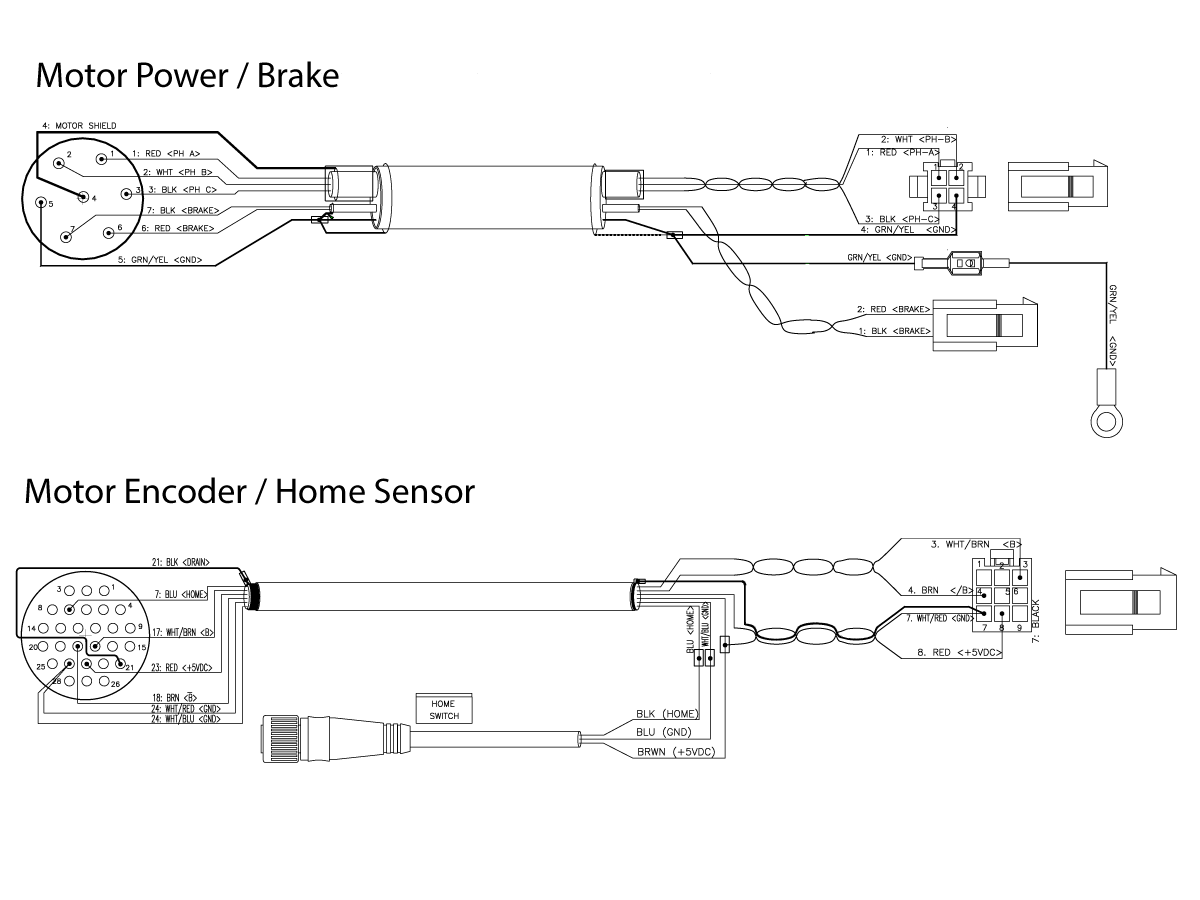
Inspect the rotary cables for wear or damage. Refer to the electrical diagram below.

Servo Amplifier

Possible Cause: The servo amplifier has a problem.

Corrective Action:

For servo amplifier troubleshooting instructions, refer to Servo Amplifier - Troubleshooting Guide.

Backlash

Possible Cause: There is lost motion or backlash in the rotary.

Corrective Action:

Test for backlash. For backlash test instructions, refer to HA5C Indexer - Backlash Test or Rotary Tables - Backlash Test.

Proximity Sensor

Possible Cause: The home proximity sensor is faulty.

Corrective Action:

For proximity sensor troubleshooting instructions, refer to Proximity Sensor - Troubleshooting Guide.

TRT70 Servo Errors

Possible Cause:

There is an O-ring inside the TRT70's 5th axis head that can cause the following symptoms:

  • Servo Humming
  • Servo Error Alarms
  • Accuracy Issues

Corrective Action: 

The O-ring has been removed on current production rotaries, but previous models will need to have it removed in the field. A plug bolt may need to be added, 40-1631 & 49-4101.

Go to the TRT70 O-ring Removal procedure for details.

Rotary Scale

Possible Cause: The rotary scale or rotary scale cable is faulty.

Corrective Action:

Make sure the cables are connected correctly.

Inspect the rotary scale cables for wear or damage. 

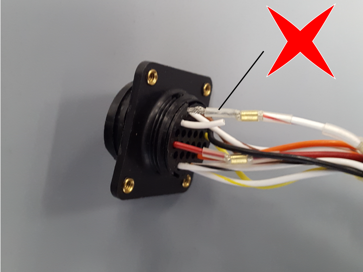
Inspect the internal rotary scale cable interface cable, and slightly pull on the wires to ensure they have a good crimp.  If the cables are connected correctly and not damaged, and the alarm persists, the rotary unit must be serviced.

For instructions on where to find a rotary repair facility and how to send your rotary unit, go to the Haas Rotary Repair Center page.

HRT450 Brake Bleeding

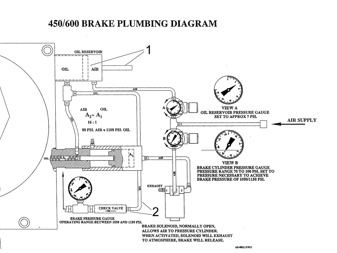
A fully extended rod indicates a full reservoir [1]

After bleeding, the rod will stick out slightly less. 

Disconnect one of the oil lines and dip the tube in oil. Push and pull the rod to fill the reservoir. Reconnect the line and perform the bleeding procedure.

Disconnect the oil line [2] and insert a tube into a hydraulic fluid container when filling the reservoir.

1

Bleeding Procedure

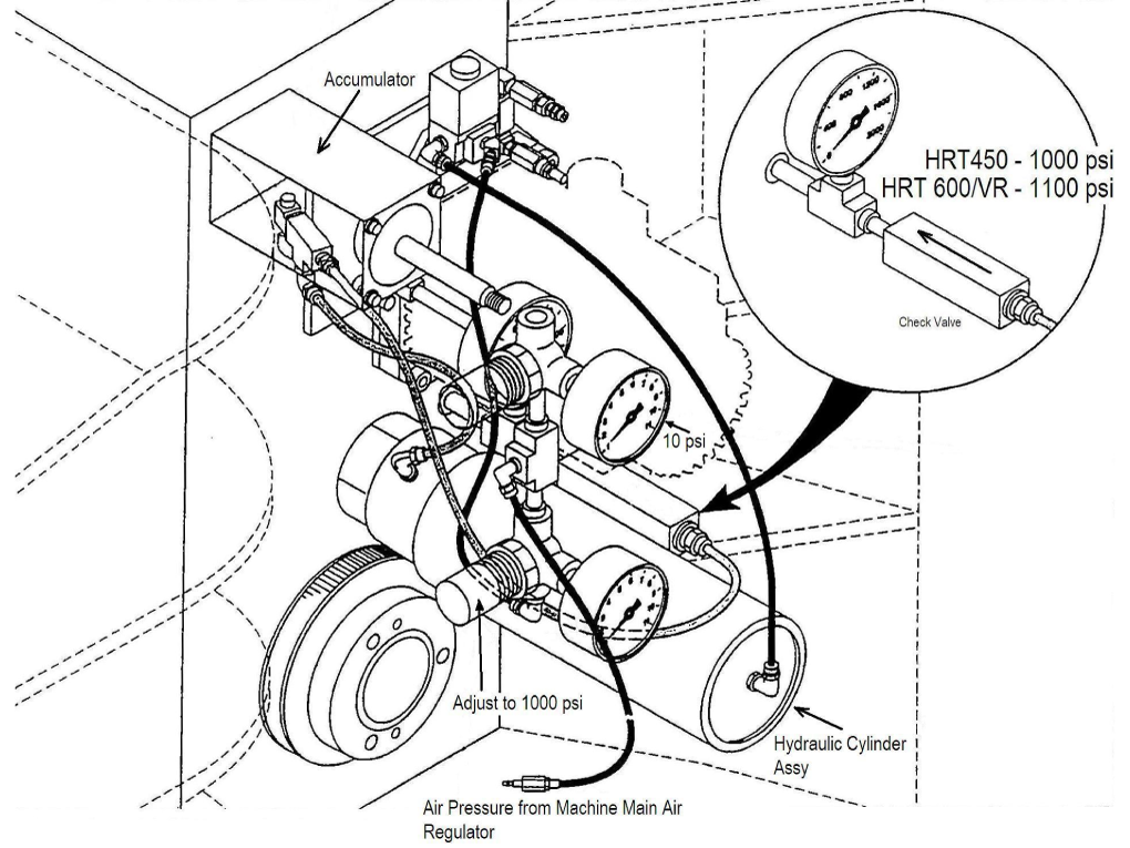
  1. Set regulator A to the max
  2. Set regulator B to zero 
  3. Loosen the top air bleed plug [1] until the air is out. 
    NOTE: Use bleed plug [2] if the top plug is not accessible.
  4. Set regulator B to 80 PSI 
  5. Set regulator A to 7 PSI

Check the main gauge. It should be 0 PSI when unclamped and 1000 PSI when clamped.

2

Use the image on the left for additional reference.

HRC Units - Rear Seal Popping Out

Do not perform any type of maintenance on the rotarty if it is under warranty, contact your Haas Factory Outlet for further assistance.

This section will explain what to do if the rear seal keeps popping out. 

NOTE:  This should only be done if the oil level has been verified and the seal is still popping out. 

1

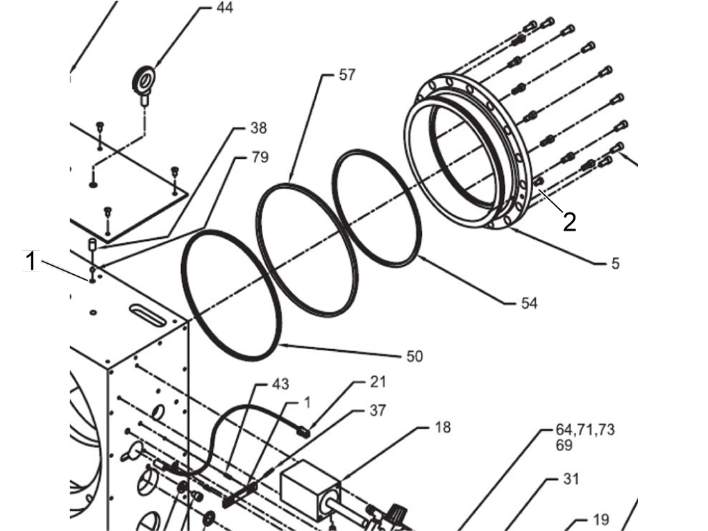
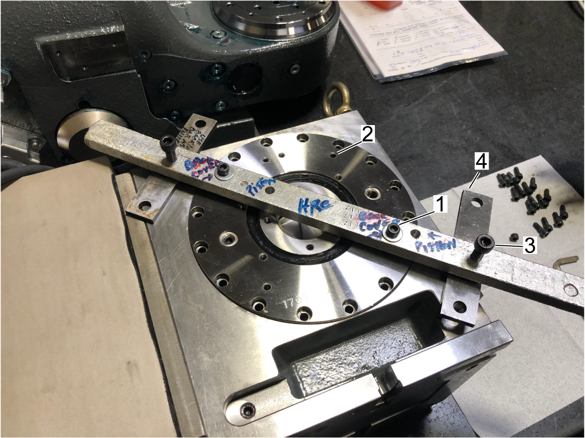
Before starting, a fixture needs to be fabricated, the fixture will have two through holes [1] to be threaded to the back of the brake cap and two threaded holes [2] on the outer section that will act like a jack and be placed on a plate [3], so it will not damage the rotary casting


An example of this is shown.

2

Remove the air supply to the table.

Place the rotary on its platter face and remove the rear M5 brake bolts.

Use the fixture made to thread to the back of the brake cap and remove it [1].

The threaded holes should be the ones denoted [2] and should be across from each other.

Using the other bolts on the threaded holes [3] as jacks, turn the bolts on each side evenly, so the plate comes off.

Make sure to use place plates of some sort [4] to prevent damage to the rotary.

3

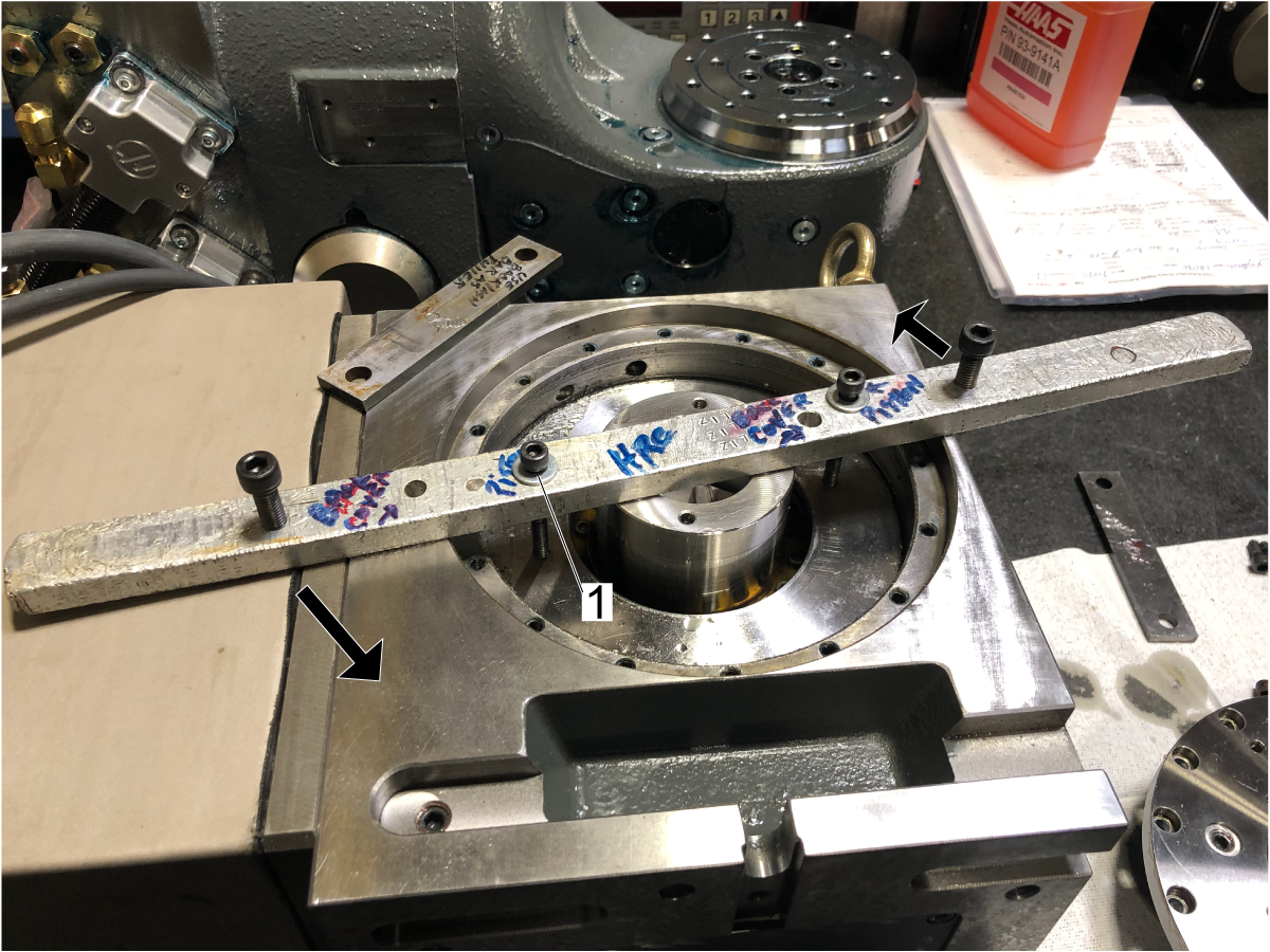
Using the same fixture, pull out the brake piston.

NOTE: Longer bolts will be needed to reach the brake piston [1]. Ensure the jack bolts are in the position indicated by the arrows to have leverage. Make sure plates are under the bolts to avoid damage to the rotary.

4

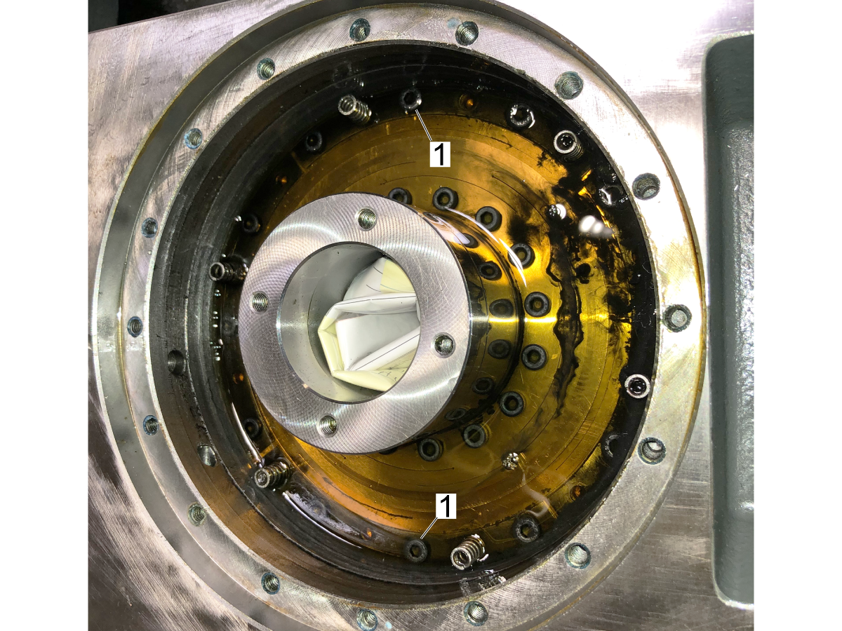
Remove the two M5 brake fasteners 180 degrees apart [1] and replace them with the modified fasteners. 

The modified fasteners have a through hole to relieve pressure under the rear brake seal. These have no part number and will need to be made.

HRT160SS/210SS Manifold Identification

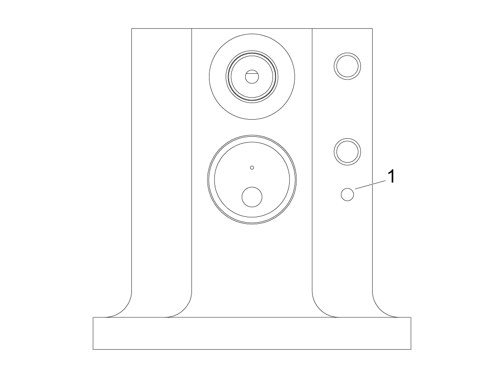
The dimple [1] indicates the brake booster manifold is an A version. 

Note: This does not apply to HRT310SS. 

Leaking Pressure Switch

Install a 0-15 PSI pressure gauge on the enclosure cover. Do not actuate the rotary brake. Check the fittings, airlines, and pressure switch for a leak if the gauge reads any pressure. If the pressure switch is the source of the leak, replace the pressure switch and reseal the cover when reinstalling.

Electrical Diagrams

SIGMA-5 Cable Diagram

Serial Data Communication Faults / Electrical Noise

Sigma-5 servo motors, non-contact encoders output serial data signal to the control. If the serial data signal is missing or becomes unreliable the control will generate a serial data communication error. Electrical noise can cause the serial data signal from the encoder to become unreliable and cause false alarms. Follow the troubleshooting guide below to help eliminate the noise in the system.

  1. Incorrect machine grounding. Make sure the ground wire size is correct. Also the ground wire should run all the way back to the electrical panel.
  2. Noise from other equipment. Make sure the machine does not share it's electrical service with another machine.
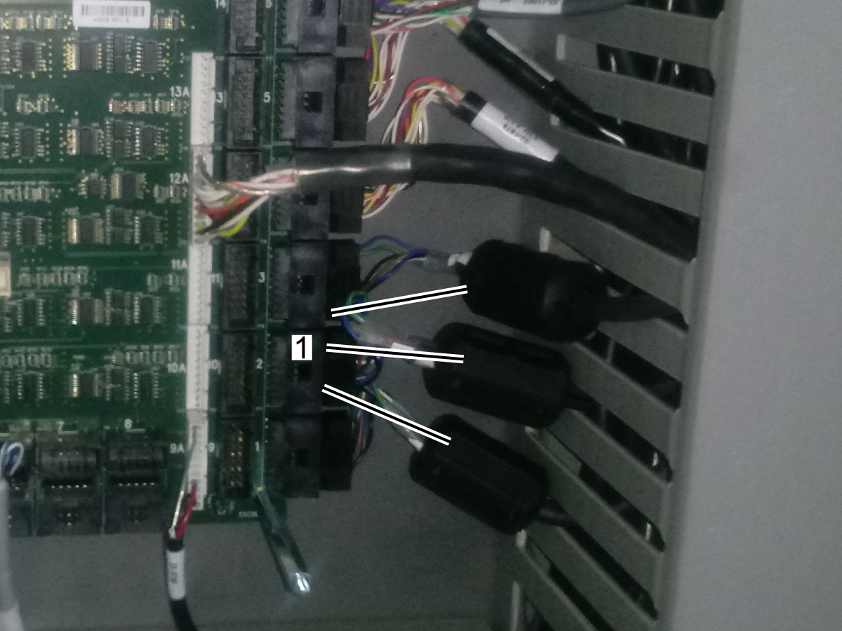
  3. Loose encoder data connectors at PCB or at the motor encoder, can cause the serial data to become unreliable. Refer to the Main Processor / Encoder Cable section.
  4. Loose ground or high voltage power connectors will induce noise into the system.
    • electrical cabinet check for loose connection at all the ground and high voltage power terminals (vector drive, wye-delta contactors, transformer..etc).
    • pendant check for loose terminal connectors.
    • spindle head check for loose ground and motor power terminals.
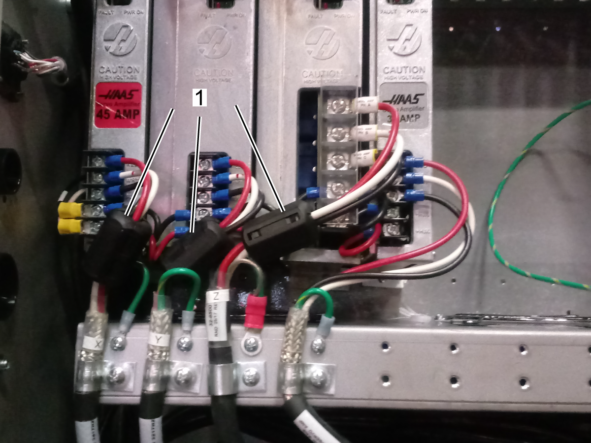
  5. The ferrite filters suppress high frequency noise produced by the amplifiers and vector drive, when servos are on. Make sure they are installed in:
    • Encoder data cables. Make sure there is a ferrite filter P/N 64 1252 installed in all the encoder data cables.
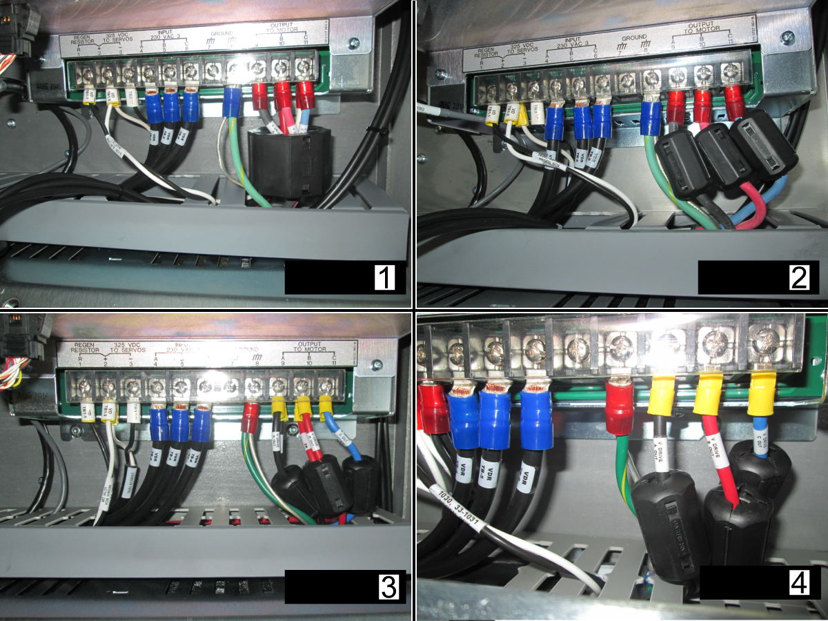
    • Axis motor power cables. Make sure there is a ferrite filter P/N 64-1252 installed in X, Y, Z axis motor power cables [1].
    • Spindle motor cables. Make sure there is a ferrite filter installed in the motor output of the vector drive.

      For a 40HP vector with 6 wire leads [1] use ferrite P/N 64-1254.

      For a 40HP vector with 3 wire leads [2] use ferrite P/N 64-1252.

      For a 20HP vector drive with 6 or 3 wire leads [3, 4] use ferrite P/N 64-1252.

  6. Cable routing. Make sure that the encoder cable is separated from high power spindle/axis/pump cables.

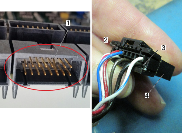
Maincon PCB / Encoder Cable

Corrective Action:

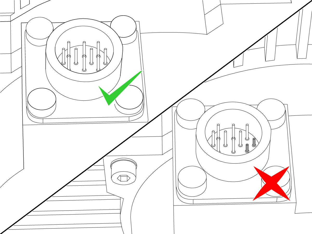
Examine the connector [1] on the Maincon. Make sure it is not damaged.

Examine the cable. Look for signs of damage or stiffness. The connector [4] has two housings [2,3] for the cable pins.

If the pins have been pushed into the motor, you must replace the motor and cable together.

Make sure the cable is firmly connected at both ends. Reseat both connections. Make sure the cable is installed in the correct connector at the Maincon or MOCON PCB.

TRT 160 and TRT 210 Breather Hole Identification

Corrective Action:

If the unit is a TRT 160 or TRT 210, ensure the breather hole on the bottom of the tilt axis casting is 0.25" in diameter. If the breather hole is smaller, it needs to be drilled to correct size.

Note: The dimple [1] indicates the location of the breather hole on a TRT 160 or TRT 210.  

Faulty Pressure Switch Identification

Possible Cause: Potential leak detected inside the enclosure. Alarm 4011 has been triggered. 

Corrective Action: If the front rubber plug is missing, it is a clear indication that the pressure switch has failed and must be replaced. 


Note: If the pressure switch is replaced on an HRTSS, the brake must  be bled. For brake bleed instructions, refer to HRTSS Brake Bleed Instructions. 

Recently Viewed Items

You Have No Recently Viewed Items Yet

Feedback
Haas Logo

美元价格不包括关税、报关费用、保险费、增值税及运费。
USD prices DO NOT include customs duty, customs fees, insurance, VAT, or freight.

人民币价格包含关税、报关费用、货运保险和增值税, 但不包括运费。
CNY prices include customs duty, customs fees, insurance, and VAT. DOES NOT include freight.

Preçário de entregas da Haas

Este preço inclui custo de envio, direitos de exportação e importação, seguro e quaisquer outras despesas incorridas durante o envio para um local em França acordado consigo na qualidade de comprador. Nenhum outro custo obrigatório pode ser acrescentado à entrega de um produto Haas CNC.

ACOMPANHE AS DICAS E TECNOLOGIA MAIS RECENTES DA HAAS…

Registe-se já!   

HAAS TOOLING ACCEPTS THE FOLLOWING:

  • Assistência e Suporte
  • Proprietários
  • Solicitar Serviço
  • Manuais do operador
  • Peças Haas
  • Pedido de reparação do rotativo
  • Guias de Pré-instalação
  • Ferramentas de compras
  • Construção e preço de uma máquina Haas nova
  • Inventário disponível
  • A lista de preços Haas
  • Financiamento CNCA
  • Sobre a Haas
  • Declaração DNSH
  • Carreiras
  • Certificações e segurança
  • Contacte-nos
  • Histórico
  • Termos e condições
  • Termos e condições de Haas Tooling
  • Privacidade
  • Garantia
  • Comunidade Haas
  • Programa Haas de Certificação
  • Haas Motorsports
  • Fundação Gene Haas
  • Comunidade de formação técnica Haas
  • Eventos
  • Junte-se à Conversa
  • Facebook
  • X
  • Flickr
  • YouTube
  • LinkedIn
  • Instagram
  • TikTok
© 2025 Haas Automation, Inc – Máquinas-Ferramenta CNC

This site is protected by reCAPTCHA and the Google Privacy Policy and Terms of Service apply.

2800 Sturgis Rd., Oxnard, CA 93030 / Toll Free: 800-331-6746
Phone: 805-278-1800 / Fax: 805-278-2255