My Haas Bienvenido:
!
Haas Tooling MyHaas/HaasConnect Sign In Register Haas Tooling MyHaas/HaasConnect Sign Out Bienvenido: Mis maquinas Última actividad Mis presupuestos Mi cuenta Mis usuarios Sign Out
Encuentre su distribuidor
  1. Select Language
    1. English
    2. Deutsch
    3. Español - ES
    4. Español - MX
    5. Français
    6. Italiano
    7. Português
    8. Český
    9. Dansk
    10. Nederlands
    11. Magyar
    12. Polski
    13. Svenska
    14. Türkçe
    15. 中文
    16. Suomi
    17. Norsk
    18. الإنجليزية
    19. български
    20. Hrvatski
    21. Ελληνικά
    22. Română
    23. Slovenský
    24. Slovenščina
    25. 한국어
    26. 日本語
    27. Українська
  • máquinas Main Menu
    • Fresadoras verticales
      Fresadoras verticales
      Fresadoras verticales View All
      • Fresadoras verticales
      • Serie VF
      • Máquinas universales
      • Series VR
      • VP-5 prismático
      • CMV con cambio de paletas
      • Mini fresadoras
      • Máquinas de moldeo
      • Centros de taladrado de alta velocidad
      • Serie de taladrado/roscado/fresado
      • Fresadoras tipo Toolroom
      • Pocket Mill
      • Fresadoras compactas
      • Serie de puentes
      • Router de láminas
      • CMV de gran tamaño
      • Fresadoras de doble columna
      • Máquinas con posicionamiento 3+2
    • Soluciones multieje
      Soluciones multieje
      Soluciones multieje View All
      • Soluciones multieje
      • Tornos con eje Y
      • Fresadoras de 5 ejes
    • Tornos
      Tornos
      Tornos View All
      • Tornos
      • Serie ST
      • Doble husillo
      • Serie Box Way
      • Tornos tipo Toolroom
      • Torno con chuck
      • Alimentador de barras Haas
      • Pocket Lathe
      • Alimentadores de barras Haas
    • Fresadoras horizontales
      Fresadoras horizontales
      Fresadoras horizontales View All
      • Fresadoras horizontales
      • Cono 50
      • Cono 40
    • Cuartos ejes y divisores
      Cuartos ejes y divisores
      Cuartos ejes y divisores View All
      • Cuartos ejes y divisores
      • Mesas giratorias
      • Divisores
      • Equipos rotativos de 5 ejes
      • Equipos rotativos extragrandes
    • Sistemas de automatización
      Sistemas de automatización
      Sistemas de automatización View All
      • Sistemas de automatización
      • Automatización de fresadora
      • Automatización del torno
      • Cargadores automáticos de piezas
      • Modelos de automatización
    • Máquinas de sobremesa
      Máquinas de sobremesa
      Máquinas de sobremesa View All
      • Máquinas de sobremesa
      • Fresadora de sobremesa
      • Torno de sobremesa
      • Simulador de control, estándar
      • Simulador de control, prémium
    • Equipo de taller
      Equipo de taller
      Equipo de taller View All
      • Equipo de taller
      • Fresadora de rodilla
      • Tornos manuales Haas
      • Sierras Haas
    • Máquinas de fabricación
      Máquinas de fabricación
      Máquinas de fabricación View All
      • Máquinas de fabricación
      • Máquinas de corte láser
      • Frenos de prensa CNC
    • ENLACES RÁPIDOS Special Series  Special Series 
      SERIE EU SERIE EU CONFIGURACIONES Y PRECIO | LISTA DE PRECIOS CONFIGURACIONES Y PRECIO | LISTA DE PRECIOS Máquinas en stock Máquinas en stock NOVEDADES NOVEDADES SU PRIMER CNC SU PRIMER CNC
      HERRAMIENTAS DE COMPRAS
      • Configure y obtenga el precio de su máquina Haas
      • Lista de precios
      • Inventario disponible
      • Financiación CNCA
      ¿QUIERE HABLAR CON ALGUIEN?

      En su Haas Factory Outlet (HFO) pueden resolver sus dudas y orientarle sobre las mejores opciones.

      CONTACT YOUR DISTRIBUTOR >
  • Opciones Main Menu
    • The Haas Control Los paquetes de opciones
      Los paquetes de opciones
      Los paquetes de opciones View All
      • Los paquetes de opciones
    • Product Image Husillos
      Husillos
      Husillos View All
      • Husillos
    • Product Image Cambiadores de herramientas
      Cambiadores de herramientas
      Cambiadores de herramientas View All
      • Cambiadores de herramientas
    • Product Image 4.º | 5.º eje
      4.º | 5.º eje
      4.º | 5.º eje View All
      • 4.º | 5.º eje
    • Product Image Torretas y herramientas vivas
      Torretas y herramientas vivas
      Torretas y herramientas vivas View All
      • Torretas y herramientas vivas
    • Product Image Palpado
      Palpado
      Palpado View All
      • Palpado
    • Extracción de virutas y refrigeración de Haas Manejo del soluble y virutas
      Manejo del soluble y virutas
      Manejo del soluble y virutas View All
      • Manejo del soluble y virutas
    • El Control Haas El Control Haas
      El Control Haas
      El Control Haas View All
      • El Control Haas
    • Product Image Opciones para productos
      Opciones para productos
      Opciones para productos View All
      • Opciones para productos
    • Product Image Herramientas y sujeción
      Herramientas y sujeción
      Herramientas y sujeción View All
      • Herramientas y sujeción
    • Product Image Portapiezas
      Portapiezas
      Portapiezas View All
      • Portapiezas
    • Product Image Soluciones de 5 ejes
      Soluciones de 5 ejes
      Soluciones de 5 ejes View All
      • Soluciones de 5 ejes
      • 5 Easy Steps to 5-Axis
    • Product Image Automatización
      Automatización
      Automatización View All
      • Automatización
    • ENLACES RÁPIDOS Special Series  Special Series 
      SERIE EU SERIE EU CONFIGURACIONES Y PRECIO | LISTA DE PRECIOS CONFIGURACIONES Y PRECIO | LISTA DE PRECIOS Máquinas en stock Máquinas en stock NOVEDADES NOVEDADES SU PRIMER CNC SU PRIMER CNC
      HERRAMIENTAS DE COMPRAS
      • Configure y obtenga el precio de su máquina Haas
      • Lista de precios
      • Inventario disponible
      • Financiación CNCA
      ¿QUIERE HABLAR CON ALGUIEN?

      En su Haas Factory Outlet (HFO) pueden resolver sus dudas y orientarle sobre las mejores opciones.

      CONTACT YOUR DISTRIBUTOR >
  • Why Haas Main Menu
      Descubra la diferencia Haas
    • Por qué Haas
    • MyHaas
    • Comunidad de capacitación
    • Industria 4.0
    • Certificado Haas
    • Testimonios de clientes
  • Servicio técnico Main Menu
      Bienvenido a Haas Service
      PANTALLA DE INICIO DE SERVICIO Manuales del operador Procedimientos instructivos Guías de resolución de problemas Mantenimiento preventivo Piezas Haas Haas Tooling Videos
  • Videos Main Menu
  • Main Menu
    • View All
      • Financing
    • View All
      • Showroom Inventory
    • ENLACES RÁPIDOS Special Series  Special Series 
      SERIE EU SERIE EU CONFIGURACIONES Y PRECIO | LISTA DE PRECIOS CONFIGURACIONES Y PRECIO | LISTA DE PRECIOS Máquinas en stock Máquinas en stock NOVEDADES NOVEDADES SU PRIMER CNC SU PRIMER CNC
      HERRAMIENTAS DE COMPRAS
      • Configure y obtenga el precio de su máquina Haas
      • Lista de precios
      • Inventario disponible
      • Financiación CNCA
      ¿QUIERE HABLAR CON ALGUIEN?

      En su Haas Factory Outlet (HFO) pueden resolver sus dudas y orientarle sobre las mejores opciones.

      CONTACT YOUR DISTRIBUTOR >
My Haas Bienvenido:
!
Haas Tooling MyHaas/HaasConnect Sign In Register Haas Tooling MyHaas/HaasConnect Sign Out Bienvenido: Mis maquinas Última actividad Mis presupuestos Mi cuenta Mis usuarios Sign Out
Encuentre su distribuidor
  1. Select Language
    1. English
    2. Deutsch
    3. Español - ES
    4. Español - MX
    5. Français
    6. Italiano
    7. Português
    8. Český
    9. Dansk
    10. Nederlands
    11. Magyar
    12. Polski
    13. Svenska
    14. Türkçe
    15. 中文
    16. Suomi
    17. Norsk
    18. الإنجليزية
    19. български
    20. Hrvatski
    21. Ελληνικά
    22. Română
    23. Slovenský
    24. Slovenščina
    25. 한국어
    26. 日本語
    27. Українська
×

Search Results

Web Pages

Images

    • <
    • 1
    • >

Haas Cobot 10 (HC10) - Lathe - Installation - AD0715

Pantalla de inicio de servicio Procedimientos instructivos Cobot Haas 10 (HC10) - Torno - Instalación - AD0715

Cobot Haas 10 (HC10) - Torno - Instalación - AD0715

- Saltar a la sección - Back to Top

5.2 Instalación del torno

Recently Updated Last updated: 10/12/2023

*Haas Cobot 10 (HC10) - Torno - Instalación


AD0715

Revisión G - 07/2026

Introduction

Este procedimiento le indica cómo instalar el Haas 10KG Cobot (HC10).

Nota: La célula de trabajo diseñada por Haas, formada por una máquina CNC y un robot, se ha evaluado en cuanto a su conformidad con los requisitos de la CE. Los cambios o variaciones en el diseño de las celdas Haas deben evaluarse para determinar el cumplimiento de las normas aplicables y son responsabilidad del usuario/integrador.

Requisitos de la máquina:

  • Versión de software  100.24.000.1001 o superior
  • HR5.51H.16.beta.20231213.zip versión o HR6.4.9.tmp20240919.zip versión.
  • ST-10/15/20/25/28 & DS-20Y/25YCubierta metálica de reinicio (cara plana)
  • Puerta  automática
  • Haas
  • Placa de E/S 34-349xB o posterior
  • 93-1000610 TÁCTIL LCD VOLANTE DE AVANCE REMOTO (RJH-XL) VOLANTE DE AVANCE REMOTO - XL  

 NOTA: Si la máquina tiene la opción de recogedor de piezas instalada. La bandeja de recogida interferirá con el robot y se deberá retirar. Es necesario realizar un panel de cubierta metálica personalizado para cubrir y sellar la abertura.

Requisitos de la herramienta:

  • Mini desarmador de cabeza plana

Fixing / Anchoring Requirements

  • The Haas 10KG Cobot (HC10) is configured and sold by Haas with a pedestal/table that is sufficiently stable when used according to Haas defined part size and weight limits. 
IMPORTANT:  For more information directly on the Hans Cobot, refer to the Hans Robot Operation Manual for Elfin Software.

There are 3 scenarios in which the cobot option can be installed on a Haas machine:

  1. Cobot option was ordered at the same time as the machine. Both the cobot and the machine are being installed together.
  2. Cobot option is ordered so that it can be installed on a previously installed machine.
  3. Cobot option was previously installed on a machine, but will now be moved to a different Haas machine.

In scenarios 2 and 3, additional parts will need to be ordered under the Serial Number of the Haas machine. See the tables below for what parts are needed in the different scenarios.

Scenario 1 - Cobot and Machine are ordered and installed together

Component Part Number Description
NO ADDITIONAL PARTS NEED TO BE ORDERED WHEN COBOT AND MACHINE ARE ORDERED TOGETHER

Scenario 2 - Cobot being field installed on existing Haas Machine

Component Part Number Description
CHECK TO SEE IF HAAS MACHINE ALREADY HAS THESE FEATURES & PARAMETERS BEFORE ORDERING
Robot Feature Unlock Parameter 93-1001031 Kit activates the robot feature on the Haas machine. To check if you need this kit, go to the Features tab on the Haas Control and check if the Robot option is highlighted. This kit does not include any physical parts.
Load Type Safety Parameters 93-1000997 Front Automation Safety Parameters - Kit is needed when the cobot will be loading parts through the front door of the Haas machine. This kit does not include any physical parts and the autodoor option would need to be purchased and installed separately.
OR  
93-1000996 Side Automation Safetly Parameters - Kit is needed when the cobot will be loading parts through the side window of the Haas machine. This kit does not include any physical parts and the autowindow option would need to be purchased and installed separately.

Scenario 3 - Cobot is being transferred from one machine to a different Haas Machine

Component Part Number Description
Cobot Integration Kit See Integration Kit Compatibility Chart Kit is needed to install parts on the Haas machine to interface with the cobot. This includes the interface box, door switches, etc... as well as the Robot Unlock Feature parameter. This kit only needs to be purchased when transferring a cobot to a new Haas machine since these parts are normally included when a cobot is ordered. 
Load Type Safety Parameters 93-1000997 Front Automation Safety Parameters - Kit is needed when the cobot will be loading parts through the front door of the Haas machine. This kit does not include any physical parts and the autodoor option would need to be purchased and installed separately.
OR  
93-1000996 Side Automation Safetly Parameters - Kit is needed when the cobot will be loading parts through the side window of the Haas machine. This kit does not include any physical parts and the autowindow option would need to be purchased and installed separately.
Safety Device 08-1899 Multi-Sided Light Curtain Kit - Kit is needed if the safety device is NOT going to be transferred from the first machine and the second Haas machine needs it's own safety device. This kit makes a 4-sided protective barrier.
OR  
08-1948 5-Sided Light Curtain Kit - Kit is needed when the safety device is NOT going to be transferred from the first machine machine and the second Haas machine needs it's own safety device. This kit makes a 5-sided protective barrier.
OR  
08-1987 Laser Area Scanner Kit - Kit is needed when the safety device is NOT going to be transferred from the first machine machine and the second Haas machine needs it's own safety device. This area scanner has a sensing distance of 4meters.

Lathe Setup

1

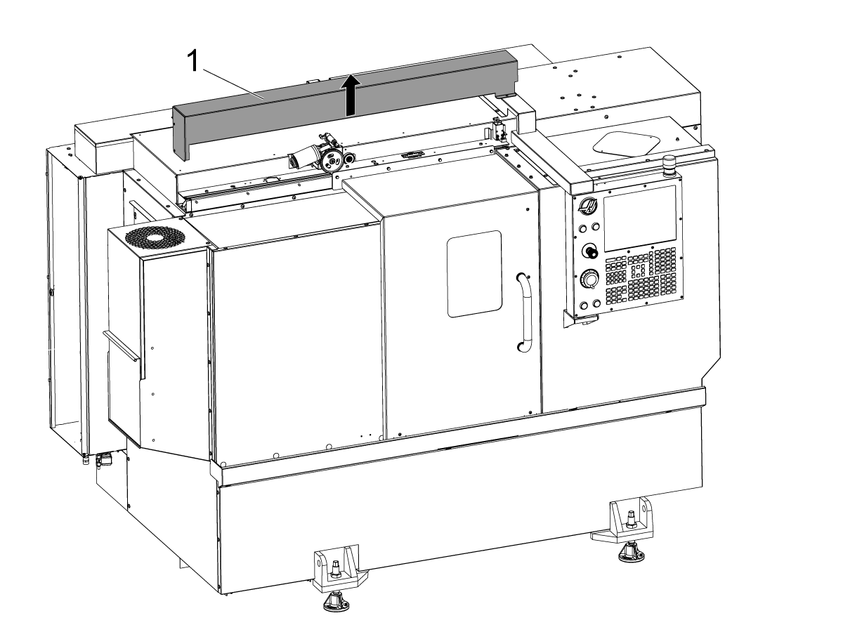
Apague la máquina.

Retire la cubierta de la puerta automática [1].

2

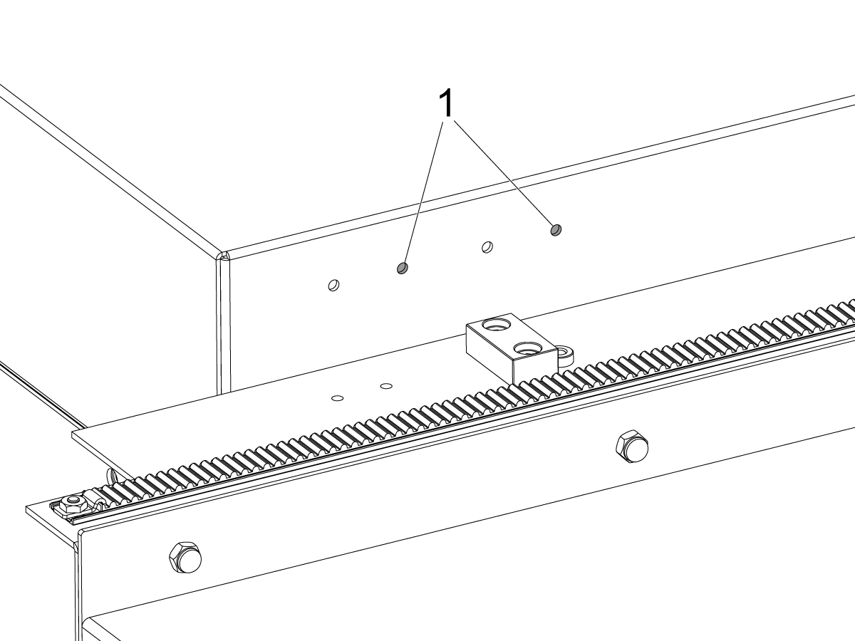
ST-20/25 & DS-20Y⁄25Y:

Para máquinas con los orificios de soporte del interruptor en el panel del techo. Instale el soporte del interruptor en el par derecho de orificios[1] para ST-20/25.

3

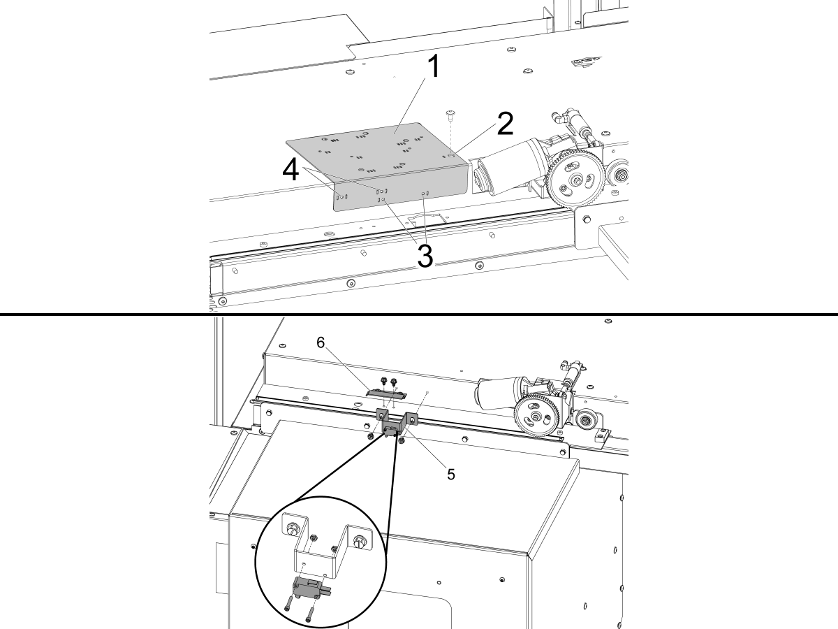
Para máquinas sin los orificios de soporte del interruptor en el panel del techo.

Utilice la guía de perforación proporcionada [1] para perforar los orificios de montaje del interruptor de estado DOOR FULLY OPEN .

Alinee el orificio situado más a la derecha en la parte superior de la guía de perforación que está marcado con una ranura [2] con el orificio de montaje de la cubierta de la puerta automática a la izquierda del motor de la puerta automática y asegúrelo con el BHCS.

ST-10/15:

  • Taladre los dos orificios de montaje de Ø 3/16" (4.7mm) a través de los orificios de guía de perforación que están marcados con una ranura [3].

ST-20/25 & DS-20Y⁄25Y:

  • Taladre los dos orificios de montaje de Ø 3/16" (4.7mm) a través de los orificios de guía de perforación que están marcados con dos ranuras en ambos lados [4].

Con los tornillos autoroscantes proporcionados, instale el DOOR FULLY OPEN conjunto de interruptores [5] y el DOOR FULLY OPEN bandera de viaje [6].

4

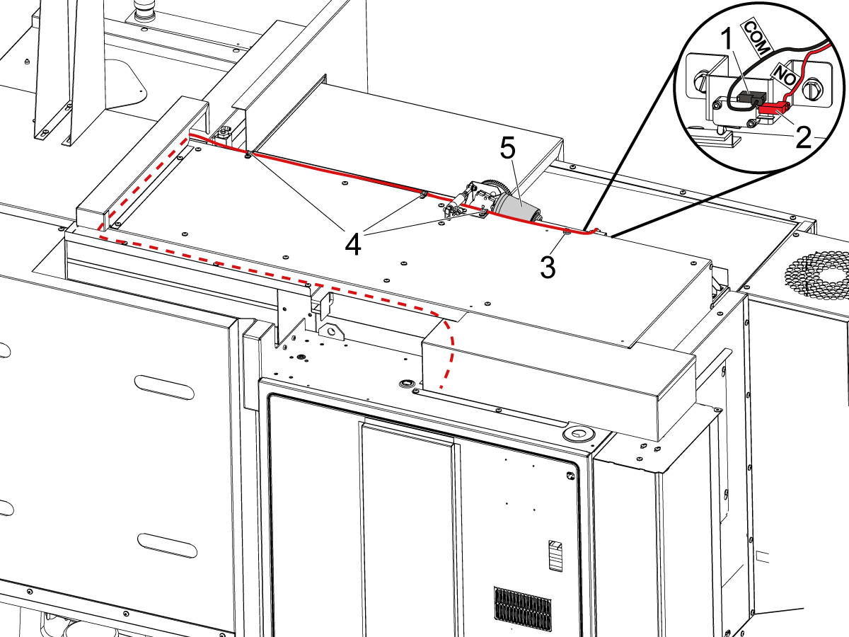
Conecte el interruptor de PUERTA COMPLETAMENTE ABIERTA como se indica:

  • NEGRO <COM> al terminal superior [1].
  • ROJO <NO> al terminal intermedio [2].

Enrute el cable en el gabinete de control como se muestra en la imagen.

NOTA: Asegúrese de instalar el clip magnético proporcionado [3] y las abrazaderas de cable [4] para mantener el cable apartado del motor móvil de la puerta automática [5].

5

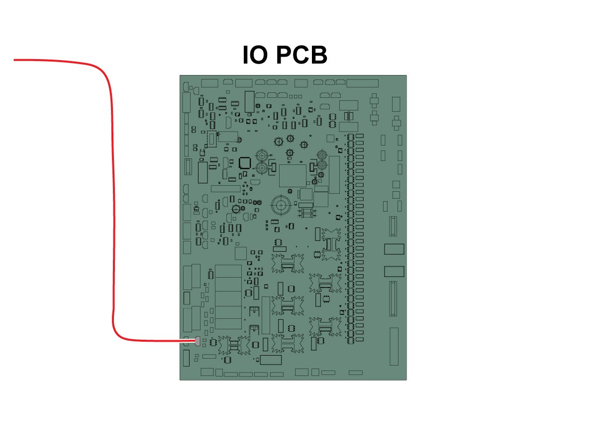
Conecte el otro extremo del cable a la entrada Puerta abierta RRI de la SIO PCB P27. 

NOTA: Asegúrese de que la máquina esté apagada

Instale la cubierta de la puerta automática.

6

  • El impulsor de resorte está hecho con un mango para adaptarse a un portaherramientas de 25 mm o 1"
  • Esta herramienta debe tomar un portaherramientas en la torreta
  • Si la máquina es una ST-10/15, necesitará dos portaherramientas vacíos para dejar suficiente espacio para el amarre
  • Programe los siguientes pasos al inicio de cualquier programa para asegurarse de que la pieza esté correctamente asentada en el plato de garras:
    • Ubique el empujador de resorte frente a la parte
    • Mueva el eje Z para comprimir el resorte aproximadamente 0.50 pulgadas o 12.7 mm
    • Abra el mandril con una pausa de un segundo.
    • Cierre el mandril con una pausa de un segundo.
    • Retraiga la torreta a la posición más segura posible

Nota: El número de parte del impulsor de resorte es: 

  • 30-12642 IMPULSOR DE RESORTE. El soporte de 25 mm o 1.0” se vende por separado.

Cobot Installation

1

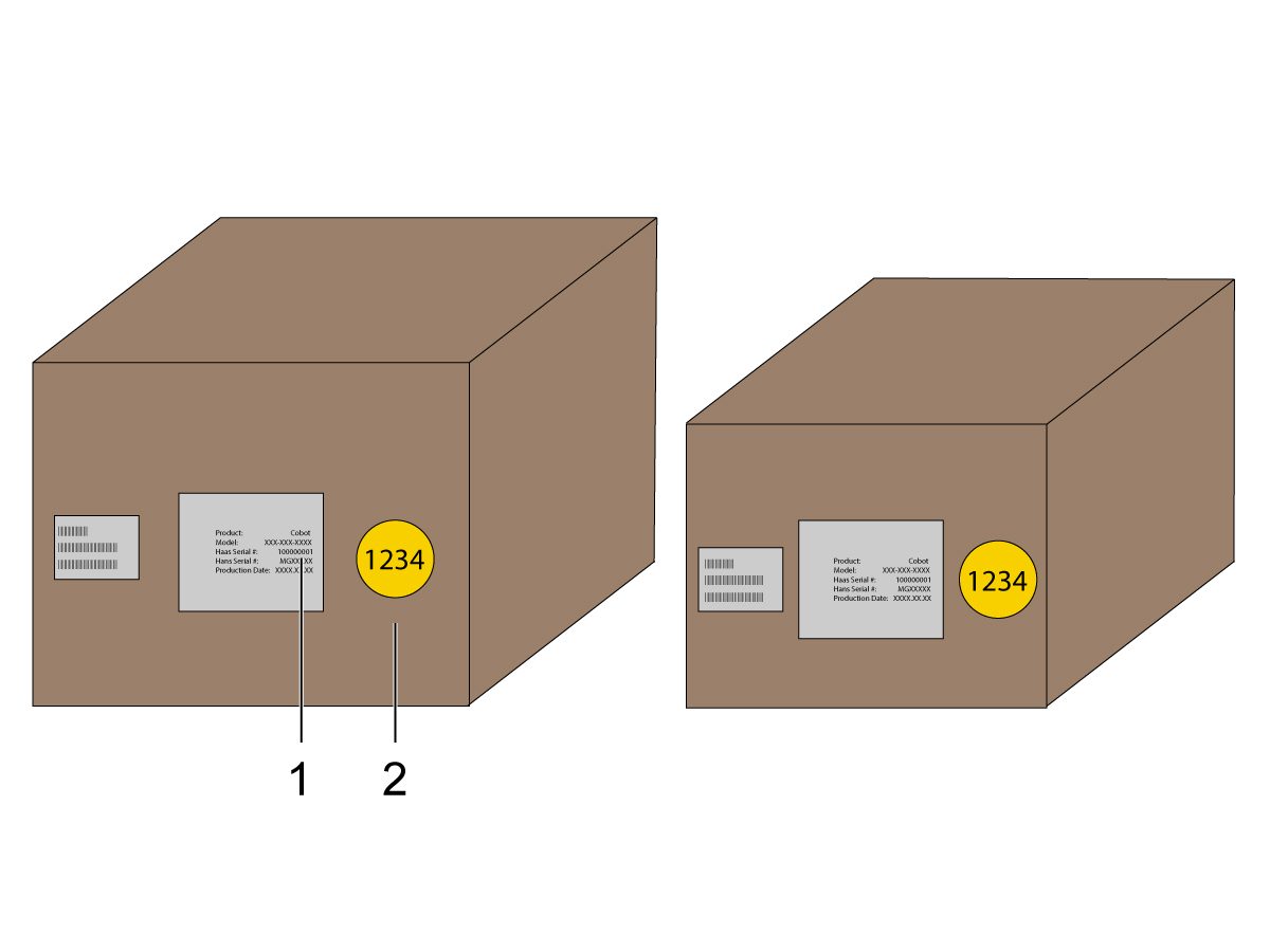
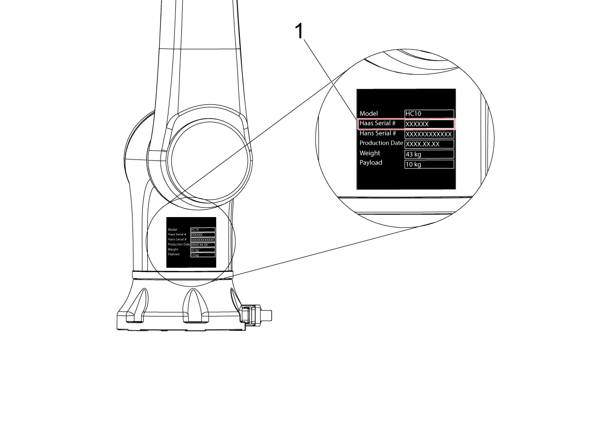
Verifique que el Coboty su caja de control sean del mismo conjunto que coincide con los números de serie que coinciden.

Hay una calcomanía blanca con el número de serie de Haas [1]. Asegúrese de que sean los mismos en ambos recuadros.

Hay una calcomanía de círculo amarillo con un número de identificación [2]. Asegúrese de que sean los mismos en ambos recuadros.

2

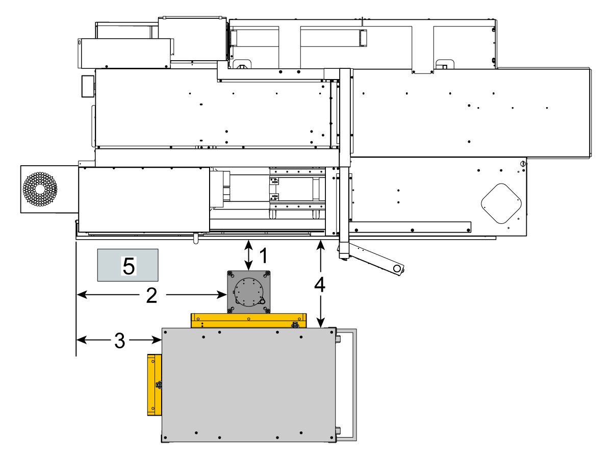
Mida estas dimensiones desde el faldón de la máquina hasta el costado del pedestal.

 Nota: Las siguientes dimensiones son las distancias recomendadas. La posición puede variar según la aplicación del usuario. 

Utilice las dimensiones de los pasos siguientes como referencia para los cobots de carga frontal y lateral.

Se recomienda combinar el Haas Cobot10 con el pedestaldel Haas Cobot. Este pedestal está configurado para ser lo suficientemente estable si se utiliza de acuerdo con los límites de peso y tamaño de pieza definidos por Haas. 

3

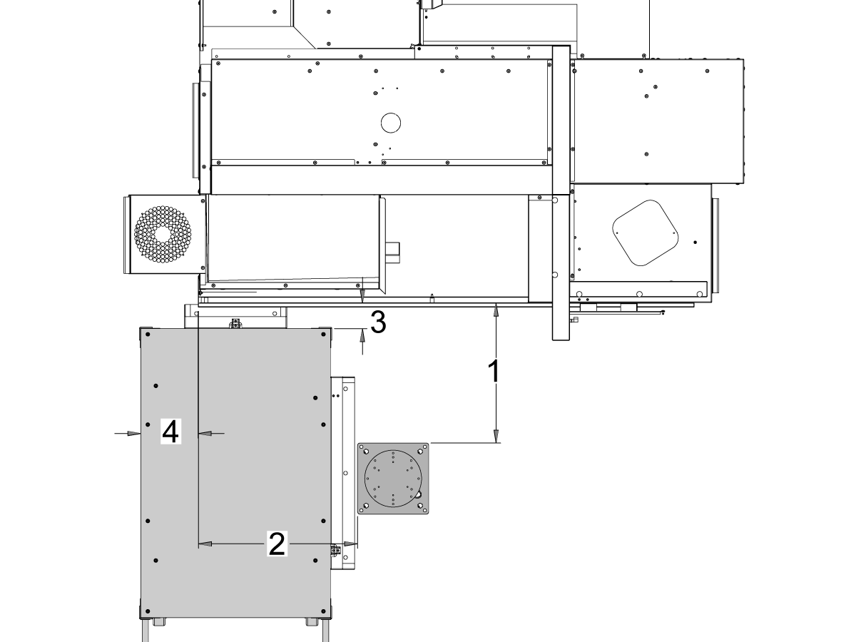
Máquinas ST-10 y ST-15:

Coloque el pedestal y la mesa de piezas en la siguiente ubicación relativa a la máquina:

Dimensión Imperial (pulgadas) Métrico (cm)
Parte delantera de la máquina a parte delantera del pedestal [1] 24.5 in 62.2 cm
Lado izquierdo de la máquina al lado izquierdo del pedestal[2] 26.25 in 66.7 cm
Parte delantera de la máquina a parte delantera del mesa de piezas[4] 5.5 in 14 cm
Lado izquierdo de la máquina al lado izquierdo de la mesa de piezas[4] 9.75 in 24.7 cm

4

Updated
Máquinas

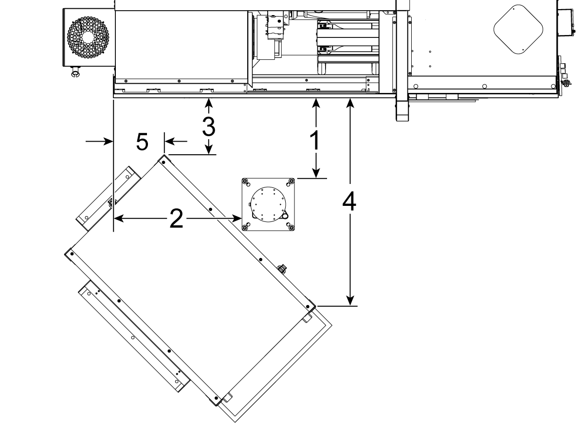
ST-20 y ST-25 & DS-20Y/25Y:

Coloque el pedestal y la mesa de piezas en la siguiente ubicación relativa a la máquina:

Dimensión Imperial (pulgadas) Métrico (cm)
Parte delantera de la máquina a parte delantera del pedestal [1] 19.5 in 49.5 cm
Lado izquierdo de la máquina al lado izquierdo del pedestal[2] 28.5 in 72.4 cm
Parte delantera de la máquina a la esquina delantera izquierda de la mesa de piezas[3] 14.5 in 36.8 cm
Parte delantera de la máquina a la esquina delantera derecha de la mesa de piezas[4] 71 in 180 cm
Parte izquierda de la máquina a la esquina delantera izquierda de la mesa de piezas[5] 10.75 in 27.3 cm

5

Máquinas ST-30/35 & DS-30Y:

Coloque el pedestal y la mesa de piezas en la siguiente ubicación relativa a la máquina:[5]

Dimensión Imperial (pulgadas) Métrico (cm)
Parte delantera de la máquina a parte delantera del pedestal [1] 8.5 in 21.6 cm
Lado izquierdo de la máquina al lado izquierdo del pedestal[2] 42.0 in 106.7 cm
Lado izquierdo de la máquina al lado izquierdo de la mesa de piezas[3] 23.5 in 59.7 cm
Parte delantera de la máquina a parte delantera del mesa de piezas[4] 24.0 in 61.0 cm

6

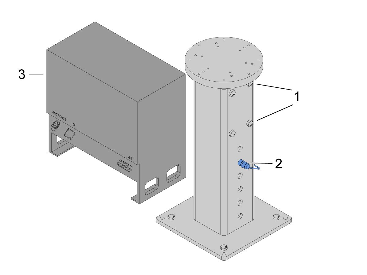
Ancle el pedestal en el suelo. Nivele el pedestal utilizando un nivel de burbuja. 

 NOTA:  para el pedestal ajustable, ajuste la altura deseada aflojando los tornillos de ajuste [1] y luego ajustando el pasador de horquilla [2]. Vuelva a apretar los tornillos de ajuste [1] antes de instalar el robot. Coloque un nivel de burbuja en la parte superior del pedestal mientras utiliza los pernos hexagonales (x4) en la base para establecer el nivel en los planos X e Y.

Coloque la caja de control del Cobot [3] directamente junto al pedestal para garantizar suficiente holgura para los cables.

7

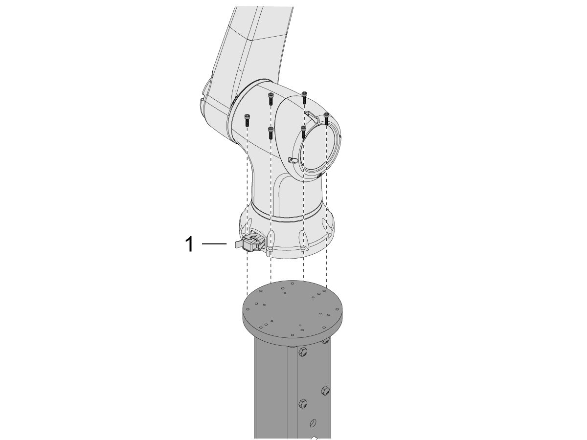
Retire el robot de la caja de envío. 

 NOTA: instale la placa adaptadora entre el pedestal y el robot si es necesario. 

Instale el Cobot en la parte superior del pedestal. 

 NOTA: Asegúrese de que el conector del cable del cobot [1] esté en escuadra con la parte delantera de la máquina. 

IMPORTANTE: El Cobot pesa aproximadamente 40 lb y debe levantarse con un dispositivo que pueda levantar con seguridad ese peso.

Después de instalar el robot, retire el hardware de elevación del robot.

8

Dentro del embalaje del Cobot, hay una bolsa pequeña [1] llena de piezas de repuesto que incluyen: 

  • Fusible
  • Tornillos (x2)
  • Llaves de la caja de control

Hay una bolsa mediana [2] con un conector M12 adicional. Este cable se puede utilizar para configurar entradas y salidas para el módulo de E/S final. 

Hay una bolsa grande [3] con papeles y una memoria USB con el software Cobot descargado.

Asegúrese de mantener estas piezas de repuesto en un lugar seguro para su uso futuro. 

Robot Electrical & Air - Installation

 DANGER: Working with the electrical services required for CNC machines is extremely hazardous and can result in serious injury or death.

Before connecting line wires to the CNC:

  • Turn off all power to the machine at the source.
  • Perform a Lockout-Tagout (LOTO) procedure to ensure the power remains off during service.
  • Verify that power has been disconnected by using an AC voltage detector on all incoming lines.

If you are uncertain about how to safely disconnect power or perform LOTO procedures:

  • Do not proceed.
  • Contact qualified personnel or obtain appropriate assistance before continuing.

Failure to follow these precautions may result in electrical shock, equipment damage, or fatal injury.

 Danger: Before beginning any work inside the control cabinet, verify that the High Voltage indicator light on the 320V Power Supply / Vector Drive has been off for a minimum of five (5) minutes. This waiting period ensures that residual voltage has dissipated and reduces the risk of electric shock.

Certain service procedures involve high-risk electrical components and may pose serious injury or fatality hazards. Technicians must not attempt any procedure unless they have a complete understanding of the steps involved and the associated risks.

If there is any uncertainty regarding a procedure, contact your Haas Factory Outlet (HFO) to arrange for a qualified service technician.

1

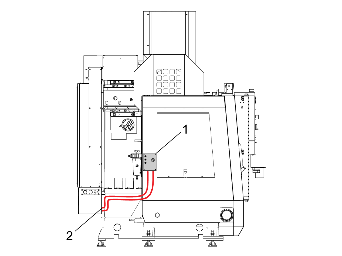
Connect Interface Box to Haas Machine:

The robot safety devices interface box 32-9018 has magnetic mounts to attach to the machine sheet metal. Mount the interface box [1] as shown in the picture.

Route the interface electrical cables [2] along the enclosure with the magnetic mounts and zipties. Route the cable through the bottom of the electrical cabinet.

NOTE: For information on upgrading the interface box to the Robot Safety Devices Interface Box, refer to the Robot Safety Devices Interface Box - Installation - AD0703. 

2

Connect Interface Box to Haas Control Cabinet:

Connect cable 33-8562C E-STOP terminal block to TB-1B [1] and connect the Setup mode terminal block to TB-3B [1] on the SIO PCB.  

Plug the user relay into K9 and K10 [2].

Verify the jumper is installed on the SIO PCB at JP1.

Connect the pigtail cable labeled P1 SIO to the SIO PCB at P1 [3]

NOTE: If the machine has a Regen Vector Drive, unplug cable 33-0634 FILTER OV TO IOPCB P1 from P1 SIO and plug it into the connector FILTER OV FAULT on cable 33-8562C. If the machine does not have a Regen Vector Drive, do not plug anything into the connector FILTER OV FAULT.

Connect the RJ-45 cable [4] to Ethernet to USB adapter [5] (33-0636).  Connect the USB connector end to the Maincon PCB J8 top port. Add a ferrite filter [6] to the USB adapter.

Mount the 24VDC Power Supply [7] to the left side of the control cabinet and plug into connector labeled 24V PS on cable 33-8562C. Connect cable 33-1281 [8] to the 24VDC Power Supply [7] and plug into P3 on the PSUP PCB. 

3

For MM/SMM CM/CL machines Without XMR

If P3 is occupied by a jumper connected from P3 [10] to P7 [9] on the PSUP PCB, a splitter cable is needed to allow the 24VDC power supply [7] to be connected to the 120VAC connectors on the PSUP. Connect the male connector of the splitter cable to P3 [10] and then connect the jumper from that cable to P7 [9] and also cable 33-1281 [8].

Note: Make sure that the jumper cable is connected where the red lines up with the red from the splitter cable.

4

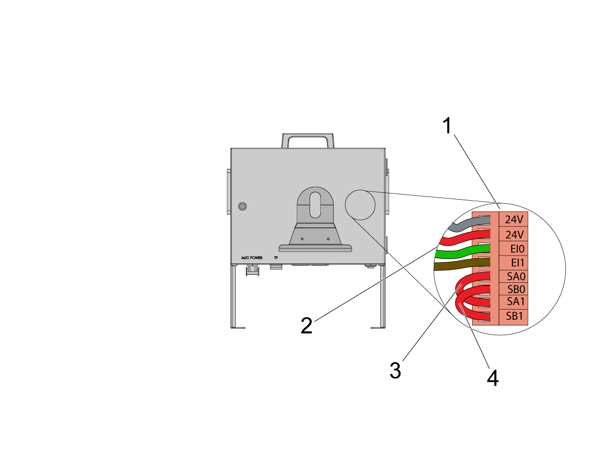
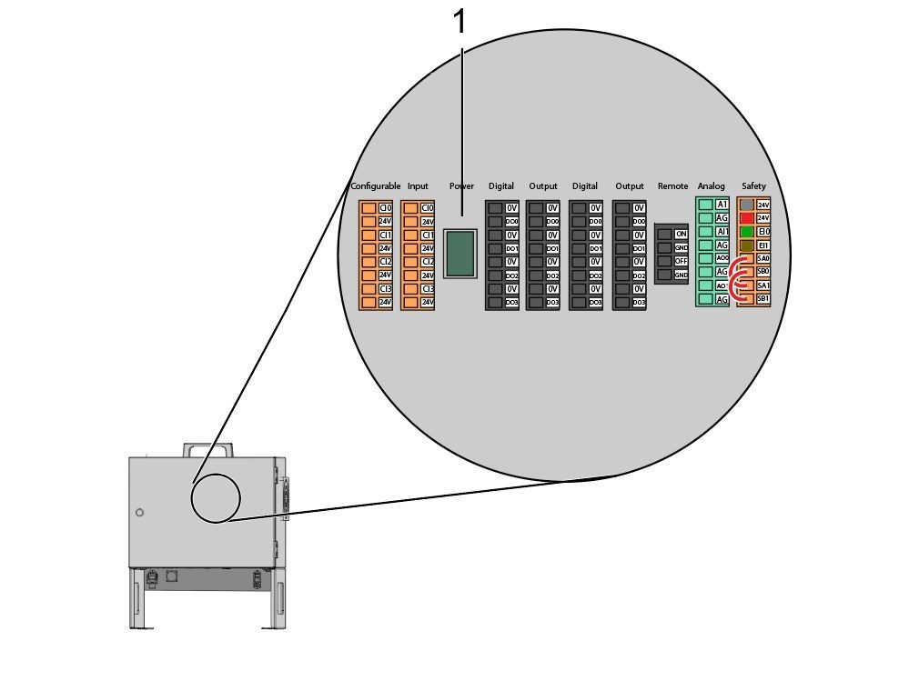
Inside the Cobot control box, install part of the robot signals cable (33-1272 or 33-1351).  To do so, remove the safety connector [1] from the Cobot control box in order to install the different colored wires into their respective location

33-1272 / 33-1351 cables [2] going to safety connector:

  • Gray wire to top 24V
  • Red wire to bottom 24V
  • Green wire to EI0
  • Brown wire to EI1
  • Jumper [3] from SA0 to SA1
  • Jumper  [4] from SB0 to SB1

 NOTE: The rest of the wires from this cable are not used. Put some electrical tape on each wire lead and Ziptie the leftover unused wires. 

5

Important: After installing all the cables from the robot signal cable, make sure that the fuse [1] remains installed at all times to protect the Cobot control box.

6

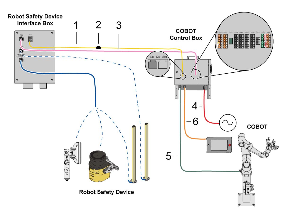
Connect Cobot to the Interface Box:

Connect the RJ45 ethernet cable [1] from the Cobot Control Box to the interface box. Add a ferrite filter [2] to the RJ-45 cable.

Connect the robot signals cable [3] from the Cobot Control Box to the interface box. 

Connect the 120 VAC Cobot Power Cable [4] to the external power source. 

Connect the robot power cable [5] from the control box to the Cobot.

Connect the teach pendant cable [6] from the control box to the teach pendant. 

NOTE: For more information regarding interlock fence, area scanner or light curtain installation, refer to the Robot Safety Device section below.

7

Make sure the Remote Jog Handle is installed onto the machine.

NOTE: For more information on the RJH-XL installation, refer to Remote Job Handle - Touch Large (RJH-XL) - Installation - AD0533. 

8

Steps 7 thru 10 are wiring and hose routing instructions for the pneumatic grippers. Refer to the grippers installation section lower on this page for the mechanical installation.

Install the dual air solenoid assembly on to the side of the pedestal while giving the airlines enough slack. Make sure it's in a position where it will not be in the way. Route the airline [1] under the machine back towards the CALM cabinet as shown.

9

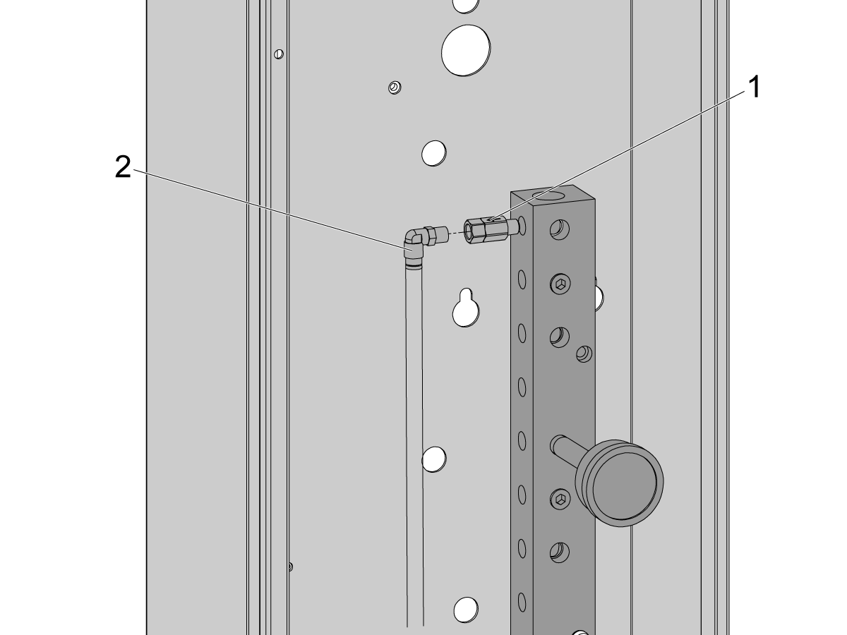
Inside the CALM cabinet, remove a plug from one of the CALM manifold ports and install the check valve [1] (58-1863) onto the port's fitting. Route the input airline [2] from the dual air solenoid assembly (from previous step) into the CALM cabinet and connect the airline to the check valve.

Turn the machine air supply ON.

10

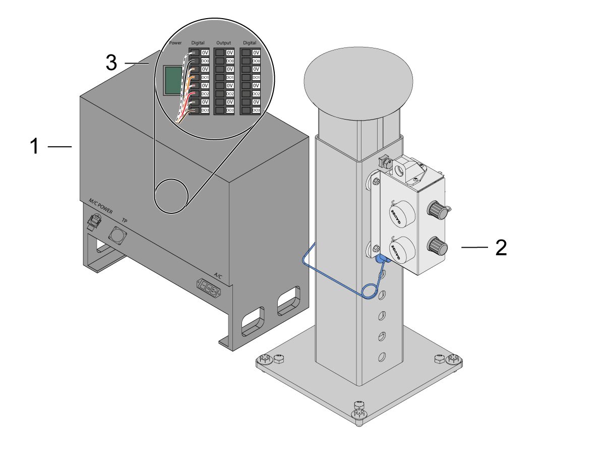
Make sure to power OFF the control box [1].

Connect the solenoid cable from the dual air solenoid assembly [2] into the Digital Output on the Cobot control box [1]. Remove the connector from Cobot control box.

11

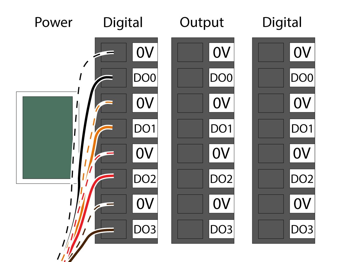
Connect the gripper solenoid power cable (33-1276 / 33-1341) to the Digital Output terminal inside the control box. Install the different colored wires into their respective location:

  • Black/white cable into 0V
  • Black cable into DO0
  • Orange/white cable into 0V
  • Orange cable into DO1
  • Red/white cable into 0V
  • Red cable into DO2
  • Brown/white cable into 0V
  • Brown cable into DO3

Power ON the control box.

Robot Safety Device

IMPORTANTE: NO UTILICE EL ROBOT HASTA QUE HAYA CONFIGURADO Y PROBADO CORRECTAMENTE EL FUNCIONAMIENTO DEL DISPOSITIVO DE SEGURIDAD.

Cortina de seguridad:

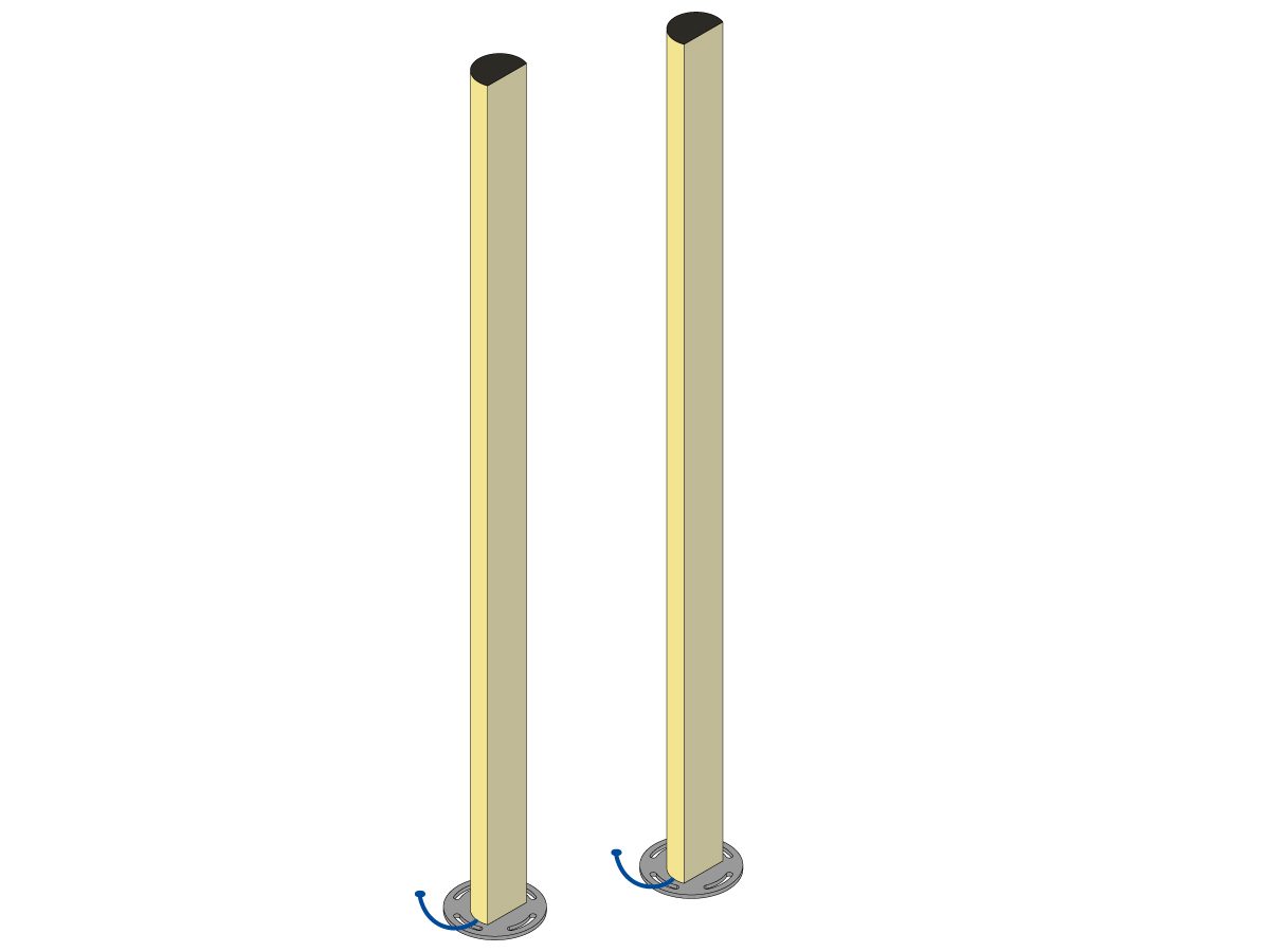
Los paquetes del Cobot vienen con el emisor y receptor de cortina de seguridad como dispositivo de seguridad predeterminado. Siga el procedimiento indicado a continuación para la instalación de la cortina de seguridad: 

Instalación de la cortina de seguridad

NOTA: Si se ordenó el lector de área o el kit HC10 Machine Ready, también habrá un receptor y emisor de cortina de seguridad 1M. Estos vienen con todos los Cobots.

Valla del robot:

Si la máquina viene equipada con la opción de valla, la valla del robot y el conjunto de interbloqueo de la puerta deben instalarse en la máquina. Siga el procedimiento indicado a continuación para la instalación:

Instalación de la valla del robot

Una vez instalada la valla, instale a continuación el panel de la valla entre la máquina y la valla del robot.

Escáner de área

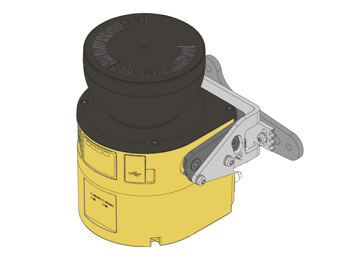
Si la máquina viene equipada con la opción de escáner de área, este debe instalarse y configurarse según el espacio. Siga el procedimiento indicado a continuación para la instalación: 

Instalación del escáner de área

First Power-UP

1

Power ON the Haas machine. 

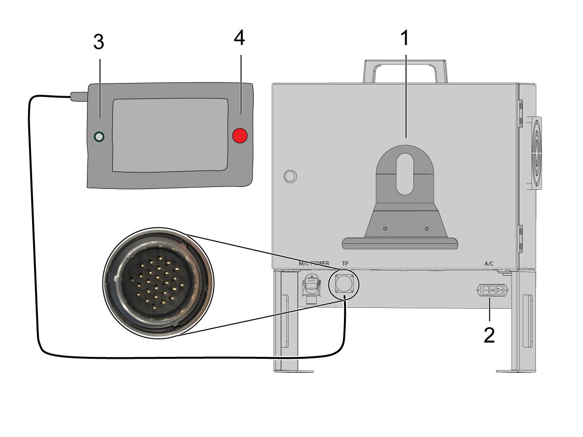
Power ON the Cobot by flipping the power switch [1].

Power ON the Cobot teach pendant by pressing the circle [2]. 

Make sure that E-STOP [3] on the Cobot teach pendant is released. 

In order to change the language, click on the language drop down menu. Choose EN for English. To confirm this setting change, the Cobot teach pendant will have a popup asking to insert the username & password. 

Enter "admin" for both the username and password. 

2

Note: The Cobot teach pendant will have a popup asking to insert the username & password. To sign into the teach pendant use these credentials:

  • Username = admin
  • Password = admin

Go into Run mode. Press Enable. 

Go into Jog mode [1].

Move each joint to it's zero location with the Move Zero buttons [2]. 

3

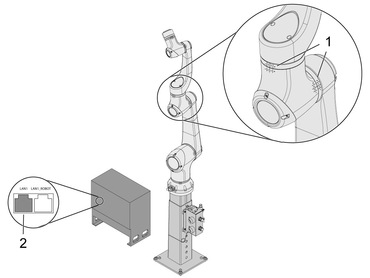
Once the robot is in it's zero location, verify that the hash lines [1] align on either side of each joint on the Cobot. 

 IMPORTANT: If any joint hash lines [1] do not align, jog the specific joint accordingly until all the hash lines [1] do align. This position will be set in the next step as the new Cobot zero position.  

Connect an ethernet cable [2] from the Cobot control box into a computer.

On the computer, change the adapter setting to enable the ethernet port. 

Note: See next steps for help on changing adapter settings.

4

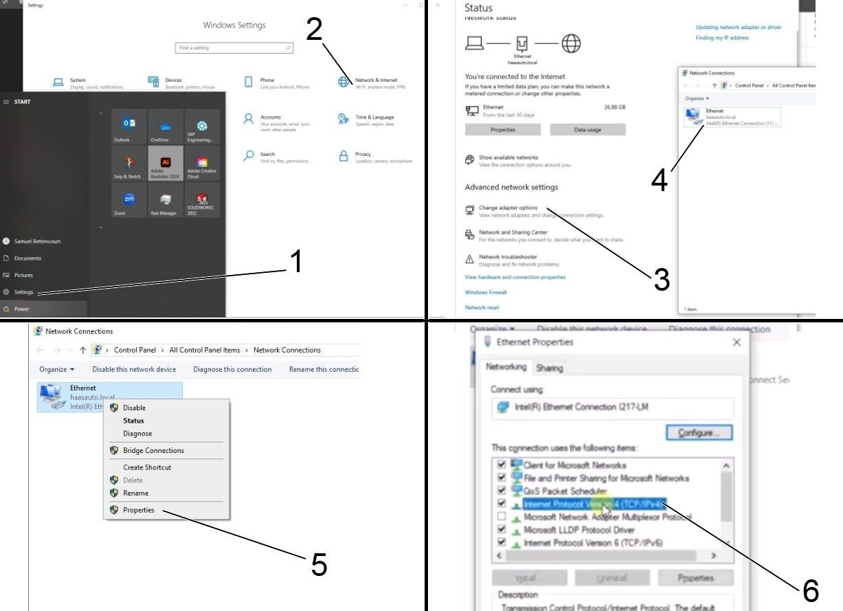
To change the adapter settings, open the settings page [1] on the computer, then click on Network & Internet [2] which will bring up the network status page.

Click on Change adapter options [3] then right click on Ethernet [4] and open up the properties window [5]. From there select the Internet Protocol Version 4 (TCP/IPv4) [6] option and click Ok. 


5

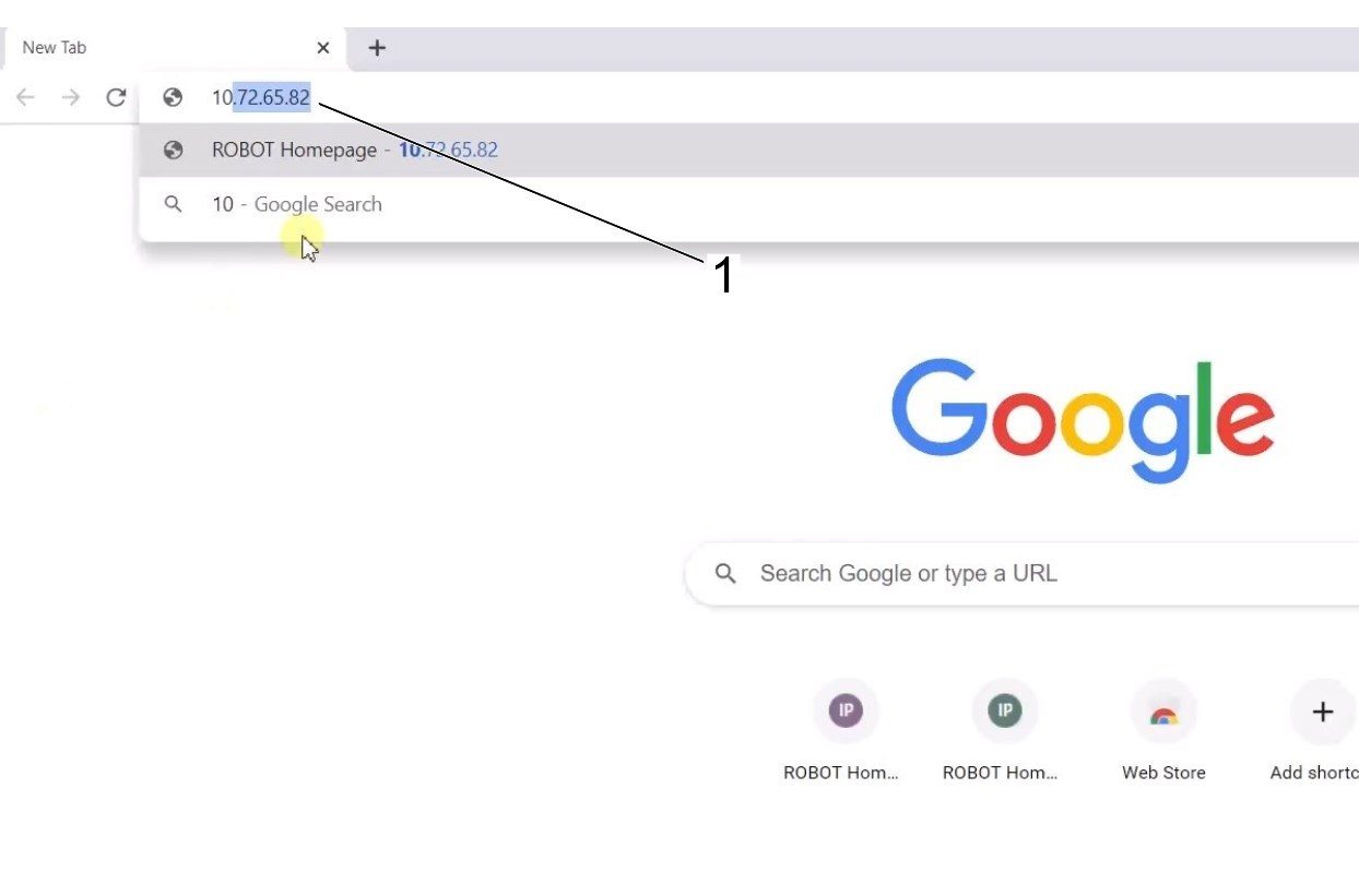
The ethernet settings will now be correct. Open a web browser window and type in the IP address of the Cobot[1]. 

Note: This is the same process as connecting a laptop to an HRP-1/2/3. For more information on connecting to the Cobot via ethernet, refer to the video on the HRP-Troubleshooting page that is in the Connect & Jog Haas Robot section. 

6

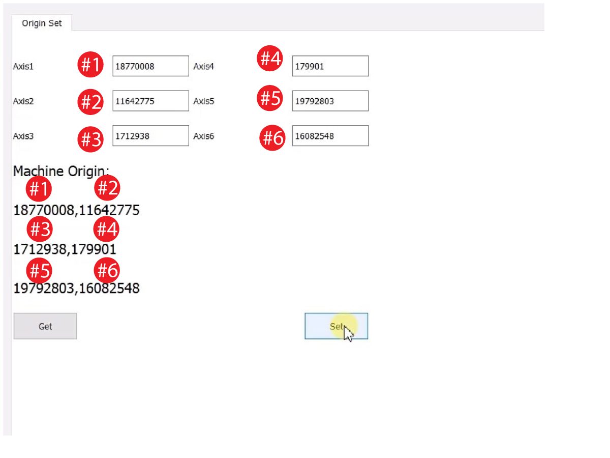
Download HRTool through HBC. On the Service section of HBC, navigate to Utilities > Documents and Software > 01 Control Software > 01 Next Generation Control > 10 Cobot Software > HRTool.zip.

Unzip the folder and navigate to HRToolsMaind.exe.

Insert the Cobot IP address found under the Systems tab.  Click Set. 

Go to the Config tab on HRTool.

Click "get" to see the actual vs. theoretical encoder values. 

Click "set" to set the theoretical to the actual encoder values. This step sets the Cobot's current position as it's new home position. 

7

Make sure that each joint's actual and theoretical encoder values match. 

NOTE: If the valuyes do not match, press "Set" again. 

8

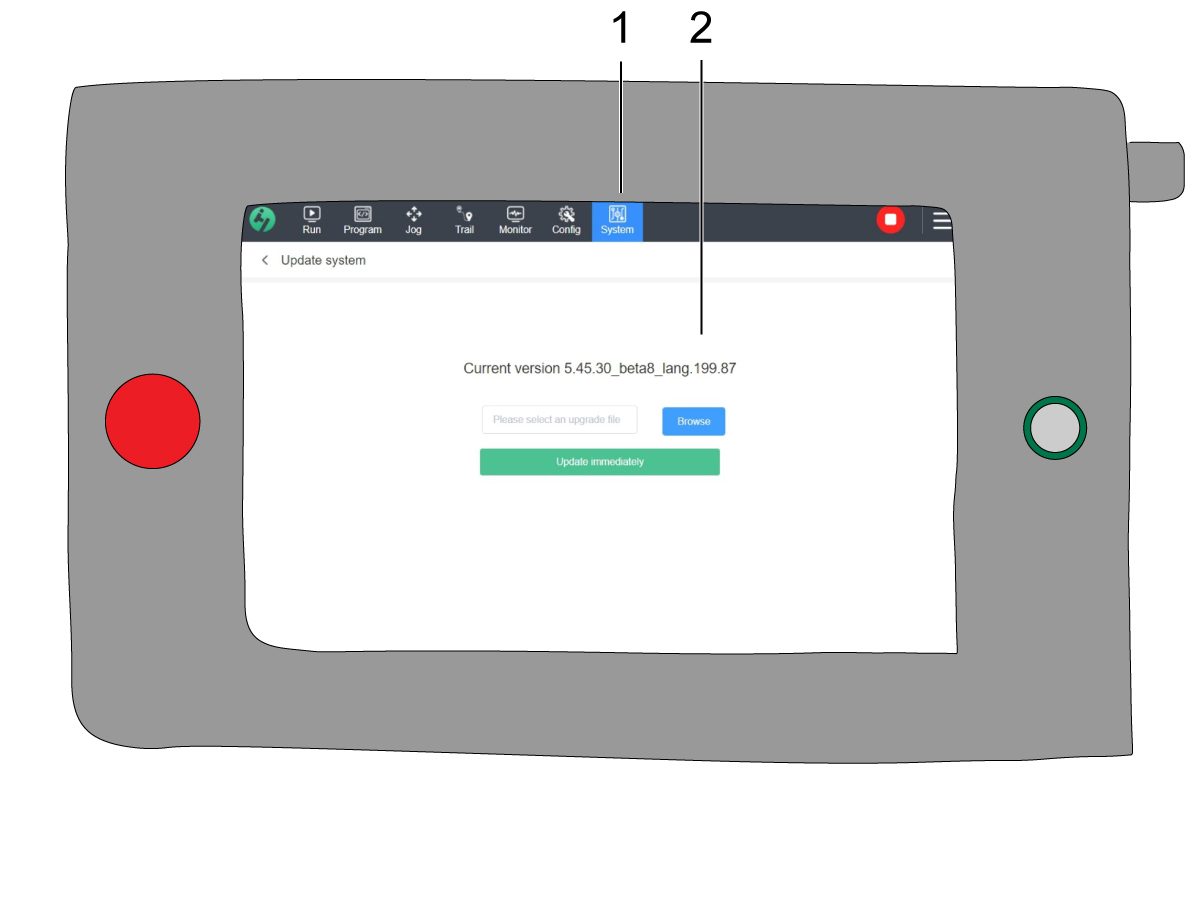
On the teach pendant, navigate to System [1] and then Update System. 

Confirm the Cobot firmware [2] is either:

  • HR5.51H.16.beta.20231213.zip
  • HR6.4.9.tmp.20240919.zip

NOTE: Firmware version HR6.4.9.tmp.20240919.zip is compatible with all size cobots.

Refer to the Haas Cobot - Maintenance chapter for the firmware update procedure. 

9

Turn on the Haas CNC.

Zero Return all Axes.

Insert Service USB key.  Go into Service mode.

Go to Parameters> Factory tab.  Change the following:

  • 1278 [1278:] Robot Ready E-Stop Enabled to TRUE
  • 2191 [694:] LIGHT CUTAIN TYPE to LC_TYPE_1
  • 2194 [:] Enable Front Door Fully Open Switch to TRUE

Note: Machines with Software Version 100.20.000.1010 or higher will need to change the following parameter:

  • 2192 [:] Light Curtain Trigger Threshold to 0

Press [SETTING].

Set the Settings:

  • 372 Parts Loader Type to 3: Robot.
  • 376 Light Curtain Enabled to On


10

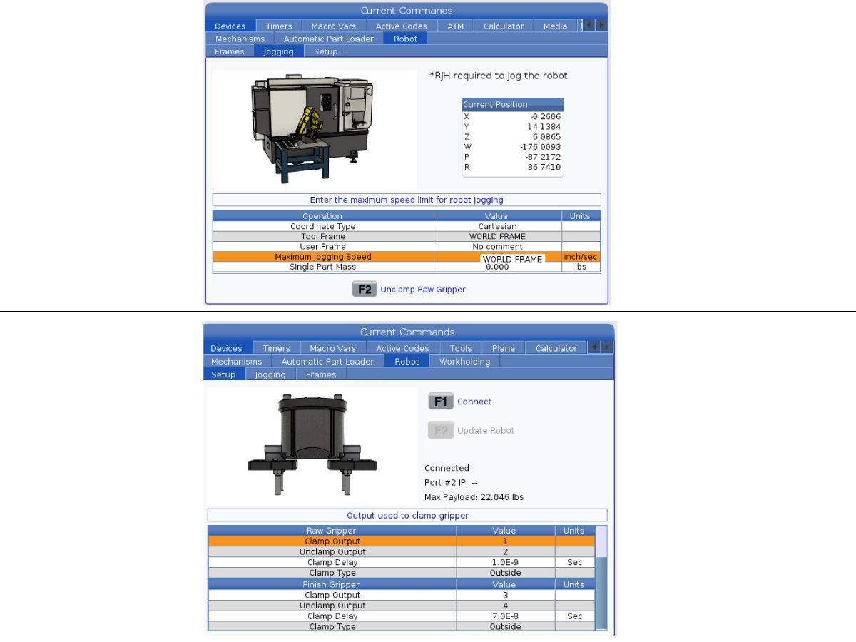
On the Haas pendant, press [CURRENT COMMANDS].

Go to Devices>Robot>Jogging tab. Change the following:

  • Maximum Jogging Speed to 7.9 inch/sec

 Note: The jogging increments on the RJH are a percentage of this max speed value. In order to decrease the distance the robot travels of each jog wheel tick, you need to change your Maximum Jogging Speed to a lower value.

Go to the Setup tab. Change the following:

  • Max Robot Speed to 118 in/sec (2000 mm/sec). 
  • Enter the Net Mass of the gripper. Refer to the layout drawings on our website (Single Gripper layout drawing OR Dual Gripper layout drawing) to get the correct value for this setting
WARNING: Setting this value incorrectly can cause the Robot Arm to not move correctly. 
 
  • Number of Grippers to the number of grippers.
  • Raw Gripper Clamp Output to 1.
  • Raw Gripper Unclamp Output to 2.
  • Raw Gripper Clamp Delay to the clamp/unclamp duration in sec.
  • Raw Gripper Clamp Type to OD/ID.
  • Finish Gripper Clamp Output to 3.
  • Finish Gripper Unclamp Output to 4.
  • Finish Gripper Clamp Delay to the clamp/unclamp duration in sec.
  • Raw Gripper Clamp Type to OD/ID.

Security Risk Level

1

IMPORTANT: Make sure to perform an appropriate risk-assessment and met all appropriate safety requirements. 

2

Based off the risk assessment, set the appropriate security risk level on the Cobot teach pendant. Navigate to Config > General Restrictions and tap of the desired security risk level [1] from 0 - 5.

Use the  "admin" code in the safety verification to change the security level.

NOTE: When the security risk level is lower, the robot will have a lower maximum speed, force, etc. When the security risk level is higher, the robot will have a higher maximum speed, force, etc. 

This security risk level will calculate the maximum allowable force, speed, power, momentum, elbow speed and elbow force [2] that the Cobot will withstand before Alarm 9150.10017 Collison Stop Error is triggered. 

IMPORTANT: The robot's programmed speed cannot be greater than the allowable speed from the security risk level. 

NOTE: For more information regarding alarms, refer to the Haas Cobot - Troubleshooting Guide. 

Activation

1

Download and load the configuration files by logging into the HAAS SERVICE PORTAL.

Download the safety automation option front/side configuration files.

Load the option configuration patch file to the control. Refer to the NEXT GENERATION CONTROL - CONFIGURATION FILE - DOWNLOAD/LOAD procedure.

2

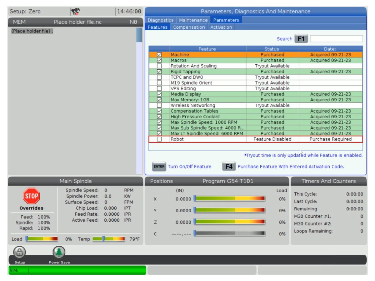
Go to Parameters > Features > Robot to verify that the robot feature has appeared on the bottom.

3

Press [CURRENT COMMANDS].

Go to Devices>Robot>Setup tab [1].

Press [E-Stop].

Press [F1] to connect the robot[2].

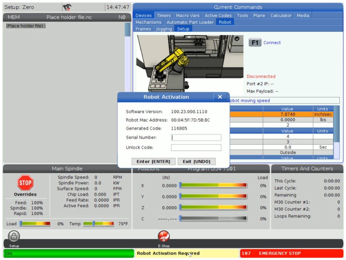
The first time connecting a robot to a machine, the robot feature will need to be unlocked. This popup shows the machine's current software version, robot mac address and a generated code. Enter this information into HBC in order to receive the unlock code.

4

On HBC, go to the Service tab [1].

On the left hand side of the screen, click on Activations [2], and then select Cobot Installation [3] to begin the process to the get the Cobot unlock code.

The first step is to enter the Machine Serial Number [4] and the Cobot Serial Number [5] in the fields on HBC.

Once you have entered the correct information, press Next [6] in the bottom right corner and continue through the steps until you receive the unlock code.

Note: Make sure you are on the Cobot Installation tab [3] and not the Robot Installation tab. The Robot Installation is only used for the Haas Robot Packages. Using the Robot Installation for the Haas Cobots will result in an invalid unlock code.

5

Enter the Cobot's Haas Serial Number[1] and the unlock code to connect the robot to the machine. 

 Note: This step can only be completed by a HFO Service Technician.

 Note: The machine needs to be activated before the Cobot is activated. Follow the Machine Activation / Time Extension - NGC procedure.

When the robot has connected with the machine, a yellow message saying Robot Activation Successful should appear at the bottom of the Haas screen.

6

Release the [E-STOP] and press RESET to clear the alarms. 

Press the [HANDLE JOG] button. 

Press the [CURRENT COMMANDS]  and go to Devices > Robot > Jogging tab.

 Note: The robot in setup mode can only be handle jogged while the F2 button the RJH is pressed. See Setup/Run mode section below.

On the Remote Handle Jog Touch press the Joint button to go into the Joints Coordinates.

Move the robot to an accessible location to install the grippers.

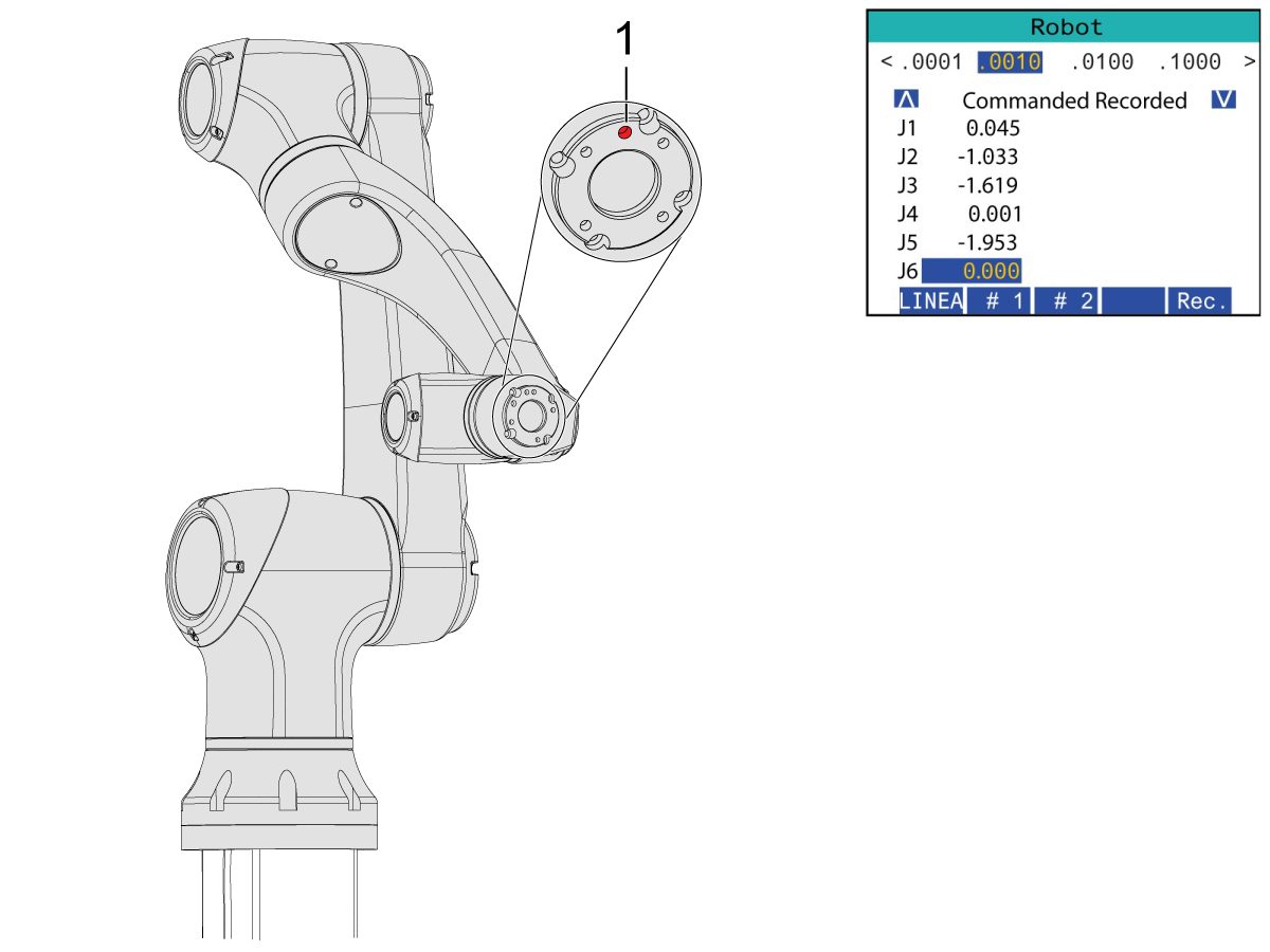
Jog J6 to 0.0000 position. The location hole should be centered on top.

Note: Press [E-STOP] before working on the robot.

Gripper Installation

1

Turn off the machine air by turning the valve in the Air/Lube cabinet and pull the pressure relief valve to release the air in the system.

2

For the Dual Action Gripper:

There are two versions of the dual-action grippers for this section, both of which have the same installation process.

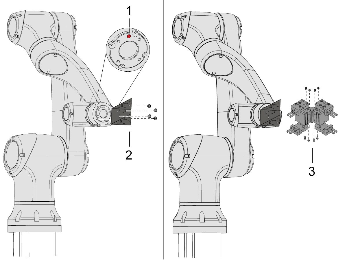
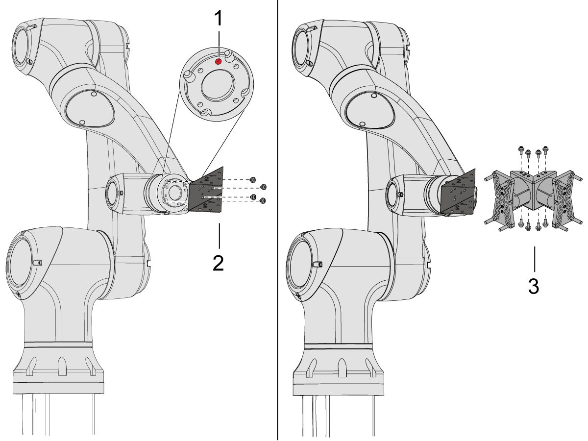
Jog the robot so that the location hole [1] is centered on top.

Install the adapter plate [2] onto the end of the robot arm.

Install the dual gripper assembly [3] onto the adapter plate [2].

NOTE: Make sure to install Gripper 1 (which has the orange and purple zip ties) onto the Gripper 1 adapter plate section. 

3

For the Angled Single Action Gripper:

Jog the robot so that the location hole [1] should be centered on top.

Install the angle adapter plate [2] to the end of the robot arm.

Install the single gripper assembly [3] onto the angle adapter plate [2]. 

4

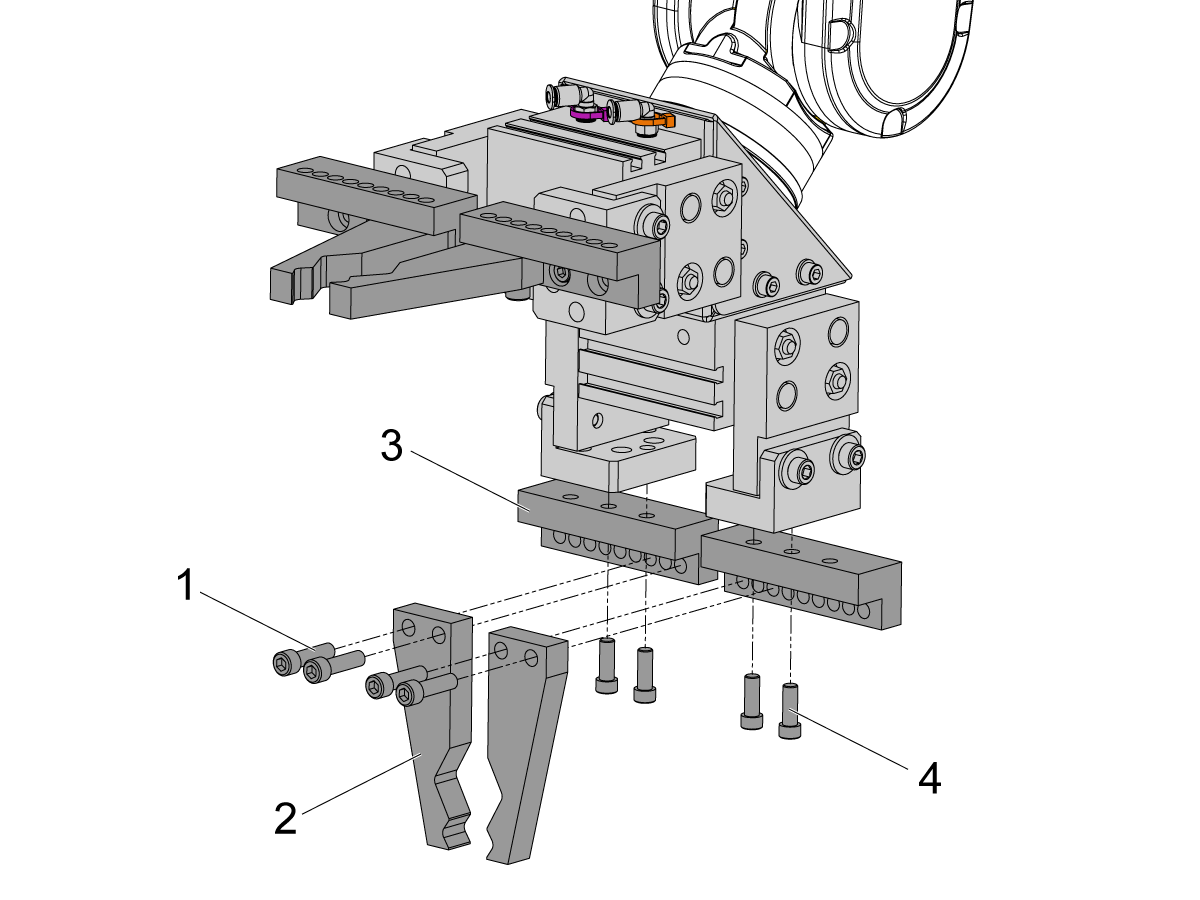
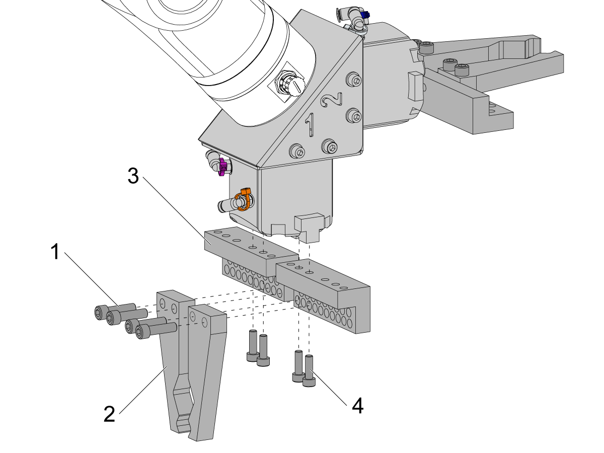
To install the bar gripper fingers, remove the slug gripper plates from the gripper bodies.

Install the Bar Gripper Bolt Plates [3] with (x8) SHCS M6 screws [4]. Torque to 10 ft-lbs.

Install the Bar Gripper Fingers [2] with (x8) SHCS 1/4-20 [1]. Torque to 13 ft-lbs.

5

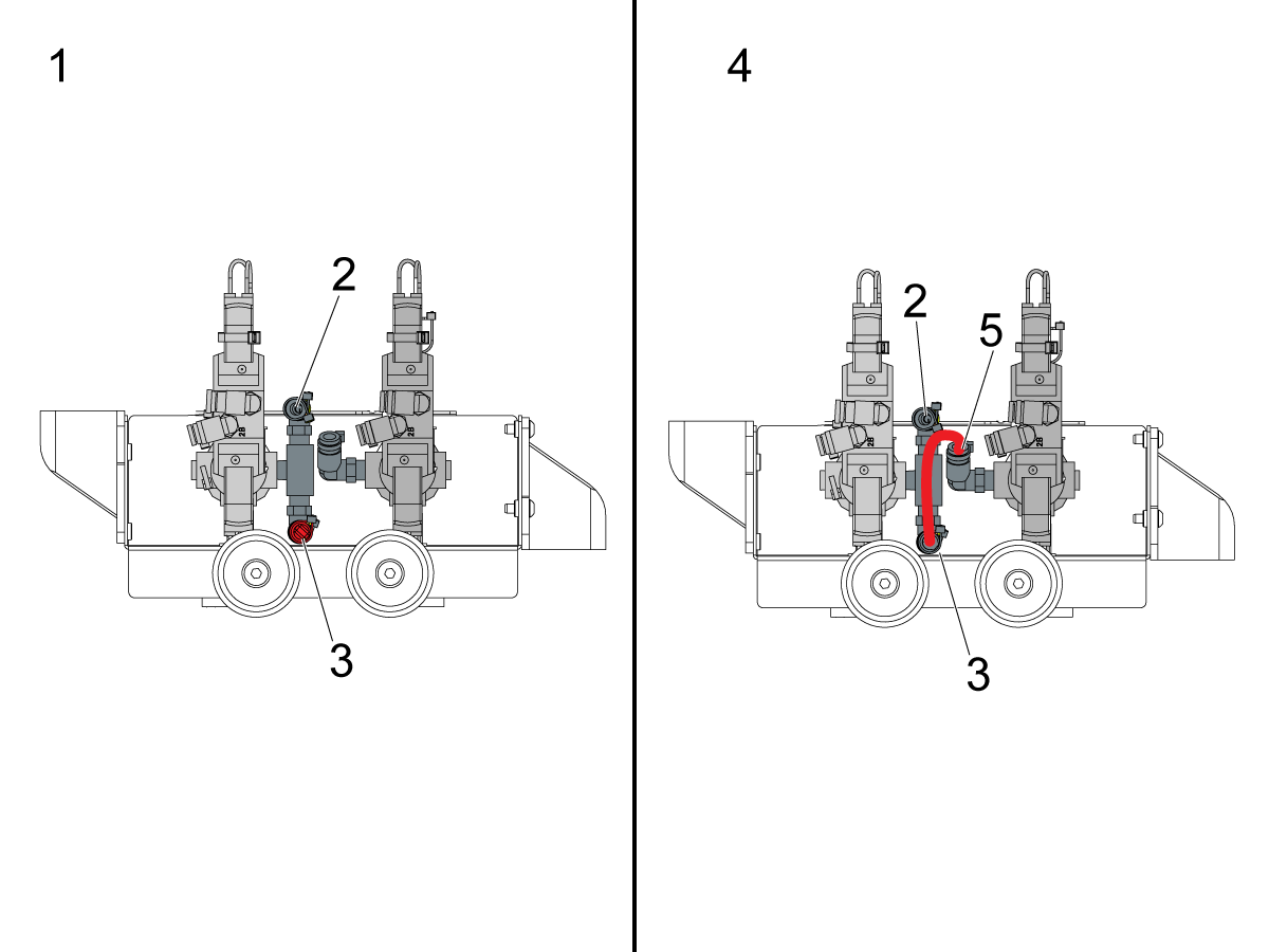
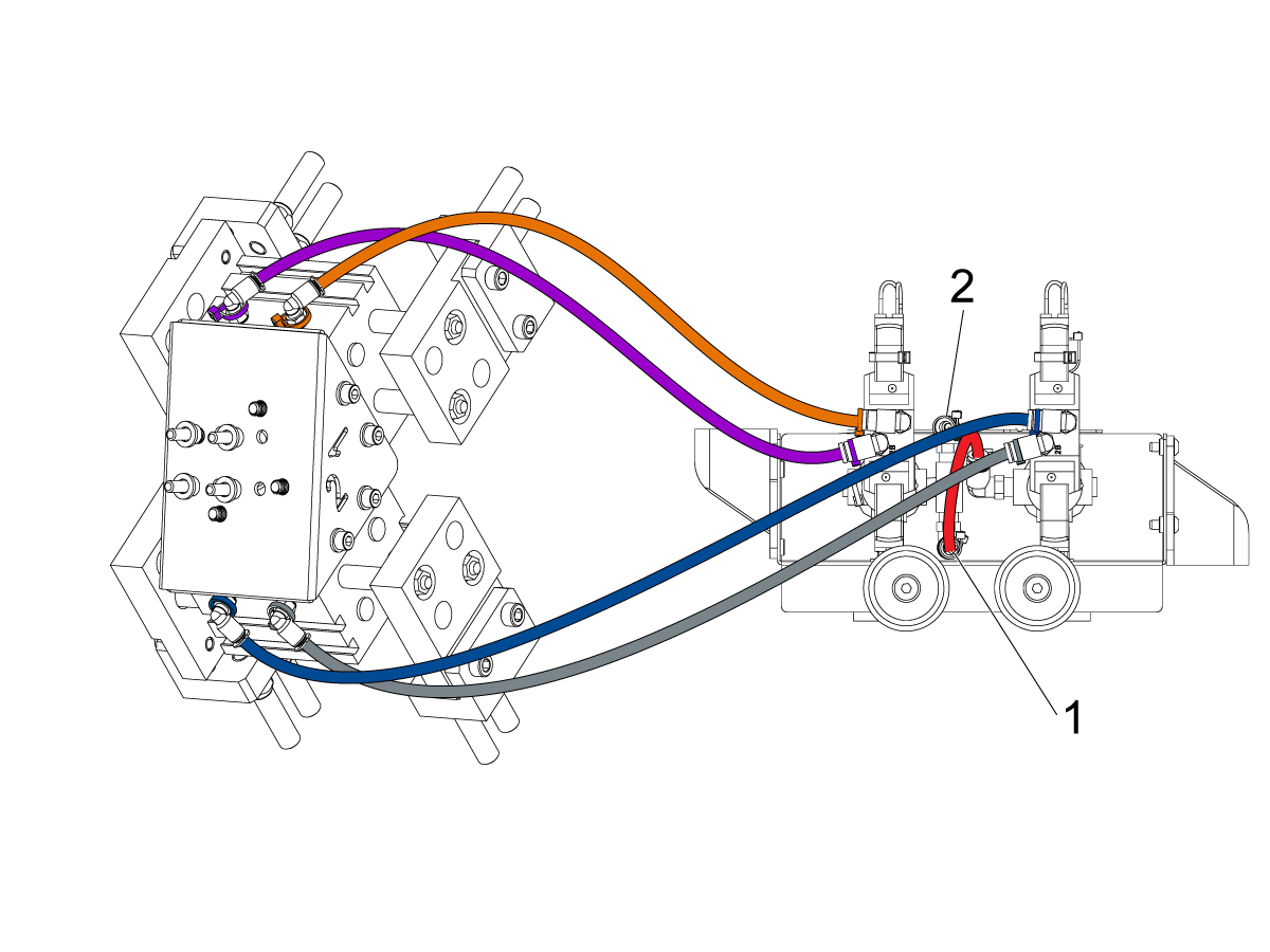
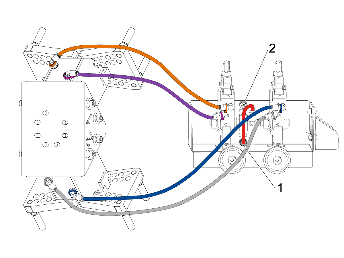
Configure the dual air solenoid assembly used for pneumatic grippers depending on single [1] or dual [2] gripper configuration. 

For single grippers [1], connect the incoming air to the to the fitting [2] and keep the plug in the other end of the fitting [3] as shown in the image.

For dual grippers [4], remove the plug in the fitting [3] and attach a small air hose to the second solenoid [5]. Then connect the incoming air hose to the fitting [2] so that both solenoids are receiving air.

6

For the Single Gripper:

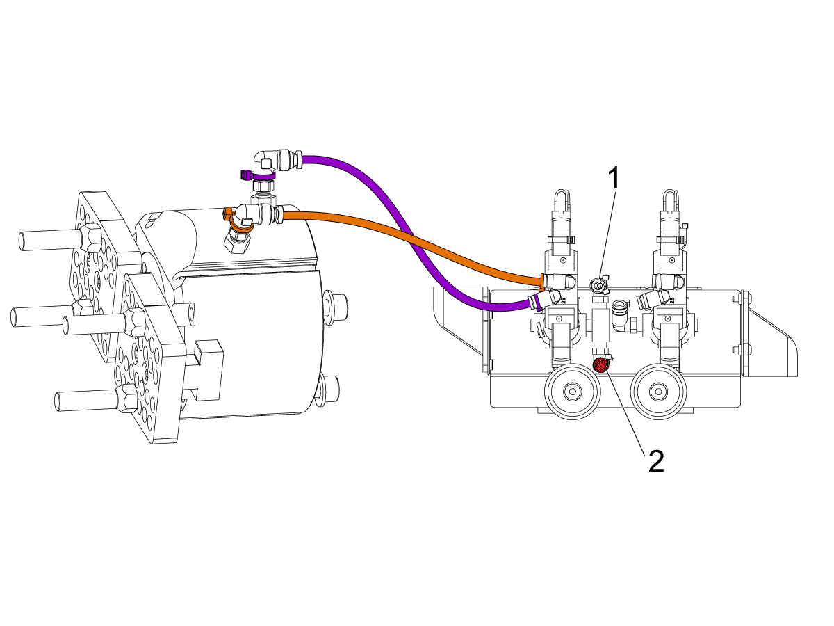
Route the (x2) air lines from the gripper to the same color coded fitting on the dual air solenoid assembly. 

Secure the air lines by wrapping them in cable conduit. Use the velcro straps to attach the cable conduit to the Cobot. Make sure there is enough slack so that cables aren't strained when Cobot is fully extended.

Insert the input air hose to the used solenoid's fitting [1]. 

Make sure the plug is installed onto the unused solenoid's fitting [2]. 

7

For the Dual Gripper:

Route the (x2) air lines from gripper #1 to the same color coded fitting on the dual air solenoid assembly. 

Route the (x2) air lines from gripper #2 to the same color coded fitting on the dual air solenoid assembly. 

Secure the air lines by wrapping them in cable conduit. Use the velcro straps to attach the cable conduit to the Cobot. Make sure there is enough slack so that cables aren't strained when Cobot is fully extended.

Insert the short airline [1] connecting the first solenoid with the second. 

Insert the input air hose to the fitting [2]. 

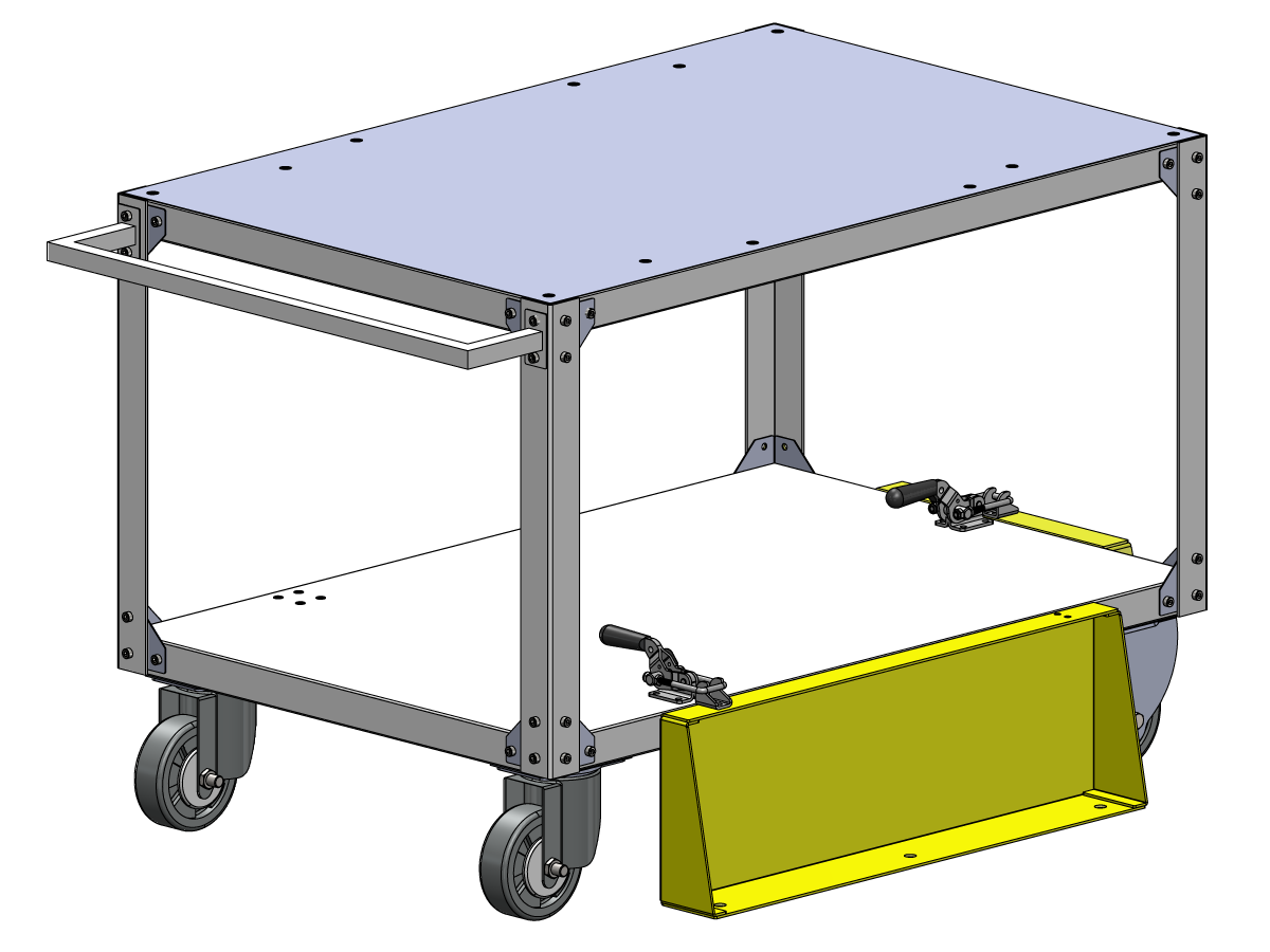
Parts Table Assembly

If the parts table option was ordered, follow the procedure below for assembly instructions:

Haas Robot - Parts Table Assembly

NOTE: If HC10 MACHINE READY KIT was purchased, there is no need to install the wheels if mounting the parts table directly into the wooden pallet. 

Verification

Test the E-stop:

  • Press each E-STOP button located on the Haas Pendant, RJH-XL, and Cobot Teach Pendant. Make sure the machine generates 107 EMERGENCY STOP alarm.  If the E-STOP button does not generate a 107 EMERGENCY STOP alarm verify the wiring. Load the latest configuration files to enable the RJH-XL.

Test the Robot Safety Device:

Make sure that there is an E-STOP or light curtain triggered icon on the Haas pendant when the robot safety device is triggered. 

  • Fence - Insert the key into the interlock, verify that the two red LED lights in the front of the interlock are OFF. Remove the key from the interlock, verify that the two red LED lights are ON. 
  • Area Scanner - Step inside the protective field, verify that the red LED lights up on the area scanner. Step outside the protective field, verify that the green LED lights up.
  • Light Curtain - Interfere the light curtain beams, verify that the light curtain triggered icon appears on the Haas pendant. Press [RESET]. Step outside of the light curtain beams, verify no icon appears on the Haas pendant. 

NOTE: If the light curtain triggered icon does not show, verify wiring, alignment and factory setting: 2191 [694:] LIGHT CURTAIN TYPE is set to LC_TYPE_1.

Test the Operation of the Grippers:

  • Verify that both grippers clamp and unclamp correctly.
  • Press the [CURRENT COMMANDS]  and go to Devices > Robot > Jogging tab.
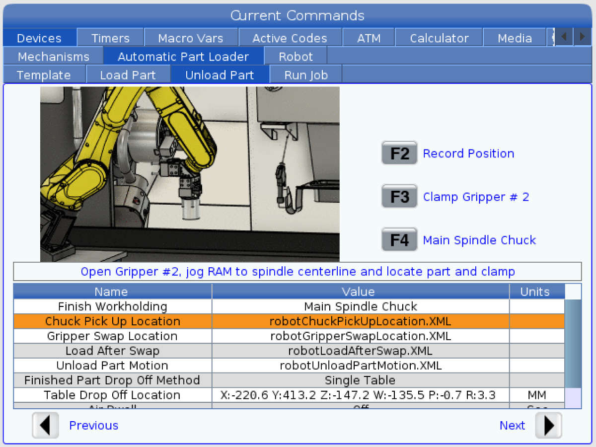
  • Press [F2] to clamp/unclamp the Finish Gripper.
  • Press [F3] to clamp/unclamp the Raw Gripper.

Test the Remote Jog Handle:

  • Undock the Remote Jog Handle
  • Press the [HANDLE JOG] button. 
  • Press the [CURRENT COMMANDS]  and go to Devices > Robot > Jogging tab.
  • On the Remote Handle Jog press the Joint button to go into the Joints Coordinates.
  • Move the robot to a safe location.

IMPORTANT: If a yellow warning message appears saying "Please activate Light Curtain or Cell Safe" while trying to job the robot, verify the safety parameter was applied by re-uploading the configuration files from HBC. 

Verify Safe / Run Mode Operation

All Haas CNC machines are equipped with a key switch on the side of the control pendant to lock and unlock setup mode. The robot will have the following behaviors depending on what mode is selected. 

  • When the Haas control is in Run mode, mode 1, triggering the robot safety device stops all motion. This motion can not be started until the robot safety device is no longer triggered.
  • When the Haas control is in Set up mode, mode 2, speed limited motion such as jogging an axis of the robot can be performed in order to program a robot's path of motion, pick up position, set a robot's tool center point, (an offset), load and pick up parts from the spindle or part holder in the machine, etc. The programmed path will also be able to be run slowly to prove out the programmed path of the robot. The robot in setup mode can only be handle jogged while the F2 button the RJH is pressed.

Haas Robot - Quick Start Guide

Después de instalar el robot, configure un trabajo siguiendo el procedimiento descrito a continuación.

Robot Haas - Guía de inicio rápido

Disable the Robot

Para deshabilitar el robot y que la máquina funcione en modo autónomo. Pulse [SETTING]. Cambie los siguientes ajustes:

  • 372 Tipo de cargador de piezas a 0: Ninguno
  • 376 Cortina de seguridad habilitada a Apagado


Recently Viewed Items

You Have No Recently Viewed Items Yet

Feedback
Haas Logo

Haas Delivered Price

This price includes shipping cost, export and import duties, insurance, and any other expenses incurred during shipping to a location in France agreed with you as a buyer. No other mandatory costs can be added to the delivery of a Haas CNC Product.

ESTÉ AL TANTO DE LO ÚLTIMO EN TECNOLOGÍA Y CONSEJOS DE HAAS...

¡Regístrese ya!   

HAAS TOOLING ACCEPTS THE FOLLOWING:

  • Servicio y asistencia
  • Propietarios
  • Solicitar mantenimiento
  • Manuales del operador
  • Piezas Haas
  • Solicitud de reparación de mesas rotativas
  • Preinstalar guías
  • Herramientas de compras
  • Configure y conozca el precio de su nueva máquina Haas
  • Inventario disponible
  • Lista de precios de Haas
  • Financiación CNCA
  • Acerca de Haas
  • Declaración de accesibilidad
  • Declaración sobre el principio DNSH
  • Cumplimiento de las normas de exportación
  • Oportunidades laborales
  • Certificados y seguridad
  • Póngase en contacto con nosotros.
  • Historia
  • Condiciones
  • Términos y condiciones de Haas Tooling
  • Privacidad
  • Garantía
  • Comunidad Haas
  • Programa de certificación de Haas
  • Haas Motorsports
  • Fundación de Gene Haas
  • Comunidad de educación técnica de Haas
  • Eventos
  • Platique con nosotros
  • Facebook
  • X
  • Flickr
  • YouTube
  • LinkedIn
  • Instagram
  • TikTok
© 2026 Haas Automation, Inc. - Máquinas herramienta CNC

This site is protected by reCAPTCHA and the Google Privacy Policy and Terms of Service apply.

2800 Sturgis Rd., Oxnard, CA 93030 / Toll Free: 800-331-6746
Phone: 805-278-1800 / Fax: 805-278-2255