My Haas Bun venit,
!
Haas Tooling MyHaas/HaasConnect Înregistrare Înregistrare Haas Tooling MyHaas/HaasConnect Deconectare Bun venit, Mașinile mele Cea mai recentă activitate Cotațiile mele Contul meu Utilizatorii mei Deconectare
Găsiți-vă distribuitorul
  1. Selectare limbă
    1. English
    2. Deutsch
    3. Español - ES
    4. Español - MX
    5. Français
    6. Italiano
    7. Português
    8. Český
    9. Dansk
    10. Nederlands
    11. Magyar
    12. Polski
    13. Svenska
    14. Türkçe
    15. 中文
    16. Suomi
    17. Norsk
    18. الإنجليزية
    19. български
    20. Hrvatski
    21. Ελληνικά
    22. Română
    23. Slovenský
    24. Slovenščina
    25. 한국어
    26. 日本語
    27. Українська
  • mașini Main Menu
    • Freze verticale
      Freze verticale
      Freze verticale View All
      • Freze verticale
      • Seria VF
      • Mașinile universale
      • Seria VR
      • VP-5 Prismatic
      • VMC-uri cu schimbarea paletelor
      • Mini Mills
      • Mașini de prelucrare matrițe
      • Centre de găurire de mare viteză
      • Seria pentru găurire/tarodare/frezare
      • Freze pentru sculărie
      • Pocket Mill
      • Freze compacte
      • Seriile portal
      • Frezele de tablă SR
      • VMC foarte mare
      • Freze cu coloană dublă
    • Soluții în mai multe axe
      Soluții în mai multe axe
      Soluții în mai multe axe View All
      • Soluții în mai multe axe
      • Strunguri pe axa Y
      • Freze pe 5 axe
    • Strunguri
      Strunguri
      Strunguri View All
      • Strunguri
      • Seria ST
      • Arbore dublu
      • Seria glisieră
      • Strunguri de sculărie
      • Strung cu mandrină
      • Strung pentru cavități
      • Alimentatoare de bare Haas
    • Freze orizontale
      Freze orizontale
      Freze orizontale View All
      • Freze orizontale
      • Con 50
      • Con 40
    • Unități rotative și indexoare
      Unități rotative și indexoare
      Unități rotative și indexoare View All
      • Unități rotative și indexoare
      • Mese rotative
      • Indexoare
      • Unități rotative în 5 axe
      • Unități rotative foarte mari
    • Sisteme de automatizare
      Sisteme de automatizare
      Sisteme de automatizare View All
      • Sisteme de automatizare
      • Automatizare freză
      • Automatizare strung
      • Încărcătoare automate de piese
      • Modele de automatizare
    • Mașini desktop
      Mașini desktop
      Mașini desktop View All
      • Mașini desktop
      • Freze desktop
      • Desktop Lathe
      • Simulator unitate de comandă, standard
      • Simulator unitate de comandă, Premium
    • Echipament pentru atelier
      Echipament pentru atelier
      Echipament pentru atelier View All
      • Echipament pentru atelier
      • Freză articulată
      • Strunguri manuale Haas
      • Ferăstraie Haas
    • Mașini de producție
      Mașini de producție
      Mașini de producție View All
      • Mașini de producție
      • Mașini de așchiere cu laser
      • Prese de îndoit CNC
    • LINK-URI RAPIDE Serie specială  Serie specială 
      SERIILE EU SERIILE EU CONFIGURAȚIE ȘI PREȚ | LISTĂ DE PREȚURI CONFIGURAȚIE ȘI PREȚ | LISTĂ DE PREȚURI Mașini în stoc Mașini în stoc CE ESTE NOU CE ESTE NOU PRIMA DVS. MAȘINĂ CNC PRIMA DVS. MAȘINĂ CNC
      CUMPĂRAREA SCULELOR
      • Configurare și preț mașină Haas
      • Listă de prețuri
      • Inventar disponibil
      • Finanțare CNCA
      AVEȚI NEVOIE DE CONSILIERE?

      O reprezentanță Haas (HFO) vă poate răspunde la întrebări și vă poate ghida spre cele mai bune opțiuni.

      CONTACT YOUR DISTRIBUTOR >
  • Opțiuni Main Menu
    • The Haas Control Pachetele cu opțiuni de valoare
      Pachetele cu opțiuni de valoare
      Pachetele cu opțiuni de valoare View All
      • Pachetele cu opțiuni de valoare
    • Product Image Arborii principali
      Arborii principali
      Arborii principali View All
      • Arborii principali
    • Product Image Schimbătoare de scule
      Schimbătoare de scule
      Schimbătoare de scule View All
      • Schimbătoare de scule
    • Product Image Axa a 4-a | 5-a
      Axa a 4-a | 5-a
      Axa a 4-a | 5-a View All
      • Axa a 4-a | 5-a
    • Product Image Capete revolver și ansamblul sculelor antrenate
      Capete revolver și ansamblul sculelor antrenate
      Capete revolver și ansamblul sculelor antrenate View All
      • Capete revolver și ansamblul sculelor antrenate
    • Product Image Palpare
      Palpare
      Palpare View All
      • Palpare
    • Gestionarea Haas a șpanului și a lichidului de răcire Gestionarea lichidului de răcire și șpanului
      Gestionarea lichidului de răcire și șpanului
      Gestionarea lichidului de răcire și șpanului View All
      • Gestionarea lichidului de răcire și șpanului
    • Unitatea de comandă Haas Unitatea de comandă Haas
      Unitatea de comandă Haas
      Unitatea de comandă Haas View All
      • Unitatea de comandă Haas
    • Product Image Opțiunile produsului
      Opțiunile produsului
      Opțiunile produsului View All
      • Opțiunile produsului
    • Product Image Scule și dispozitive de fixare
      Scule și dispozitive de fixare
      Scule și dispozitive de fixare View All
      • Scule și dispozitive de fixare
    • Product Image Sistemul de suport piesă
      Sistemul de suport piesă
      Sistemul de suport piesă View All
      • Sistemul de suport piesă
    • Product Image Soluții în 5 axe
      Soluții în 5 axe
      Soluții în 5 axe View All
      • Soluții în 5 axe
      • 5 Easy Steps to 5-Axis
    • Product Image Automatizare
      Automatizare
      Automatizare View All
      • Automatizare
    • LINK-URI RAPIDE Serie specială  Serie specială 
      SERIILE EU SERIILE EU CONFIGURAȚIE ȘI PREȚ | LISTĂ DE PREȚURI CONFIGURAȚIE ȘI PREȚ | LISTĂ DE PREȚURI Mașini în stoc Mașini în stoc CE ESTE NOU CE ESTE NOU PRIMA DVS. MAȘINĂ CNC PRIMA DVS. MAȘINĂ CNC
      CUMPĂRAREA SCULELOR
      • Configurare și preț mașină Haas
      • Listă de prețuri
      • Inventar disponibil
      • Finanțare CNCA
      AVEȚI NEVOIE DE CONSILIERE?

      O reprezentanță Haas (HFO) vă poate răspunde la întrebări și vă poate ghida spre cele mai bune opțiuni.

      CONTACT YOUR DISTRIBUTOR >
  • Why Haas Main Menu
      Descoperiți diferența Haas
    • De ce Haas
    • MyHaas
    • Comunitate pentru învățare
    • Industry 4.0
    • Certificare Haas
    • Mărturiile clienților
  • Service Main Menu
      Bine ați venit la departamentul de Haas Service
      PAGINA PRINCIPALĂ SERVICE Manualele de utilizare Instrucțiuni de folosire Ghiduri de depanare Întreținerea preventivă a mașinii Piese Haas Haas Tooling Videoclipuri
  • Videoclipuri Main Menu
  • Main Menu
    • View All
      • Financing
    • View All
      • Showroom Inventory
    • LINK-URI RAPIDE Serie specială  Serie specială 
      SERIILE EU SERIILE EU CONFIGURAȚIE ȘI PREȚ | LISTĂ DE PREȚURI CONFIGURAȚIE ȘI PREȚ | LISTĂ DE PREȚURI Mașini în stoc Mașini în stoc CE ESTE NOU CE ESTE NOU PRIMA DVS. MAȘINĂ CNC PRIMA DVS. MAȘINĂ CNC
      CUMPĂRAREA SCULELOR
      • Configurare și preț mașină Haas
      • Listă de prețuri
      • Inventar disponibil
      • Finanțare CNCA
      AVEȚI NEVOIE DE CONSILIERE?

      O reprezentanță Haas (HFO) vă poate răspunde la întrebări și vă poate ghida spre cele mai bune opțiuni.

      CONTACT YOUR DISTRIBUTOR >
My Haas Bun venit,
!
Haas Tooling MyHaas/HaasConnect Înregistrare Înregistrare Haas Tooling MyHaas/HaasConnect Deconectare Bun venit, Mașinile mele Cea mai recentă activitate Cotațiile mele Contul meu Utilizatorii mei Deconectare
Găsiți-vă distribuitorul
  1. Selectare limbă
    1. English
    2. Deutsch
    3. Español - ES
    4. Español - MX
    5. Français
    6. Italiano
    7. Português
    8. Český
    9. Dansk
    10. Nederlands
    11. Magyar
    12. Polski
    13. Svenska
    14. Türkçe
    15. 中文
    16. Suomi
    17. Norsk
    18. الإنجليزية
    19. български
    20. Hrvatski
    21. Ελληνικά
    22. Română
    23. Slovenský
    24. Slovenščina
    25. 한국어
    26. 日本語
    27. Українська
×

Rezultatele căutării

Web Pages

Images

    • <
    • 1
    • >

Haas Cobot 10 (HC10) - Lathe - Installation - AD0715

Pagina principală Service Instrucțiuni de folosire Haas Cobot 10 (HC10) - Strung - Instalare - AD0715

Haas Cobot 10 (HC10) - Strung - Instalare - AD0715

- Salt la secțiune - Back to Top

5.2 Instalarea strungului

Recently Updated Last updated: 10/12/2023

Haas Cobot 10 (HC10) - Strung - Instalare


AD0715

Revizia G – 07/2026

Introduction

Această procedură vă va arăta cum să instalați cobotul Haas de 10 kg (HC10).

Notă: Celula de lucru proiectată Haas a fost alcătuită dintr-o maşină CNC şi un robot a fost evaluat pentru respectarea cerinţelor CE. Modificările sau variaţiile de design al celulelor Haas trebuie evaluate pentru respectarea standardelor aplicabile şi sunt responsabilitatea utilizatorului/integratorului.

Cerințe privind mașina:

  • Versiunea 100.24.000.1001 sau o versiune ulterioară
  • Versiunea HR5.51H.16.beta.20231213.zip sau Versiunea HR6.4.9.tmp20240919.zip .
  • ST-10/15/20/25/28 și DS-20Y/25Y Capac din tablă reinițializat (față plată)
  • Ușă automată  Haas
  • 34-349xB placă I/O sau o versiune ulterioară
  • ECRAN TACTIL LCD MANETĂ DE COMANDĂ AVANS RAPID DE LA DISTANȚĂ (RJH-XL) 
  • 93-1000610   MANETĂ DE COMANDĂ AVANS RAPID DE LA DISTANȚĂ - XL  

 NOTĂ: Dacă mașina are instalată opțiunea de recuperator de piese. Tava de prindere va interfera cu robotul şi va trebui eliminată. Va trebui realizat un panou personalizat din tablă pentru a acoperi și etanșa deschiderea.

Cerințe privind sculele:

  • Mini șurubelniță cu cap plat

Fixing / Anchoring Requirements

  • The Haas 10KG Cobot (HC10) is configured and sold by Haas with a pedestal/table that is sufficiently stable when used according to Haas defined part size and weight limits. 
IMPORTANT:  For more information directly on the Hans Cobot, refer to the Hans Robot Operation Manual for Elfin Software.

There are 3 scenarios in which the cobot option can be installed on a Haas machine:

  1. Cobot option was ordered at the same time as the machine. Both the cobot and the machine are being installed together.
  2. Cobot option is ordered so that it can be installed on a previously installed machine.
  3. Cobot option was previously installed on a machine, but will now be moved to a different Haas machine.

In scenarios 2 and 3, additional parts will need to be ordered under the Serial Number of the Haas machine. See the tables below for what parts are needed in the different scenarios.

Scenario 1 - Cobot and Machine are ordered and installed together

Component Part Number Description
NO ADDITIONAL PARTS NEED TO BE ORDERED WHEN COBOT AND MACHINE ARE ORDERED TOGETHER

Scenario 2 - Cobot being field installed on existing Haas Machine

Component Part Number Description
CHECK TO SEE IF HAAS MACHINE ALREADY HAS THESE FEATURES & PARAMETERS BEFORE ORDERING
Robot Feature Unlock Parameter 93-1001031 Kit activates the robot feature on the Haas machine. To check if you need this kit, go to the Features tab on the Haas Control and check if the Robot option is highlighted. This kit does not include any physical parts.
Load Type Safety Parameters 93-1000997 Front Automation Safety Parameters - Kit is needed when the cobot will be loading parts through the front door of the Haas machine. This kit does not include any physical parts and the autodoor option would need to be purchased and installed separately.
OR  
93-1000996 Side Automation Safetly Parameters - Kit is needed when the cobot will be loading parts through the side window of the Haas machine. This kit does not include any physical parts and the autowindow option would need to be purchased and installed separately.

Scenario 3 - Cobot is being transferred from one machine to a different Haas Machine

Component Part Number Description
Cobot Integration Kit See Integration Kit Compatibility Chart Kit is needed to install parts on the Haas machine to interface with the cobot. This includes the interface box, door switches, etc... as well as the Robot Unlock Feature parameter. This kit only needs to be purchased when transferring a cobot to a new Haas machine since these parts are normally included when a cobot is ordered. 
Load Type Safety Parameters 93-1000997 Front Automation Safety Parameters - Kit is needed when the cobot will be loading parts through the front door of the Haas machine. This kit does not include any physical parts and the autodoor option would need to be purchased and installed separately.
OR  
93-1000996 Side Automation Safetly Parameters - Kit is needed when the cobot will be loading parts through the side window of the Haas machine. This kit does not include any physical parts and the autowindow option would need to be purchased and installed separately.
Safety Device 08-1899 Multi-Sided Light Curtain Kit - Kit is needed if the safety device is NOT going to be transferred from the first machine and the second Haas machine needs it's own safety device. This kit makes a 4-sided protective barrier.
OR  
08-1948 5-Sided Light Curtain Kit - Kit is needed when the safety device is NOT going to be transferred from the first machine machine and the second Haas machine needs it's own safety device. This kit makes a 5-sided protective barrier.
OR  
08-1987 Laser Area Scanner Kit - Kit is needed when the safety device is NOT going to be transferred from the first machine machine and the second Haas machine needs it's own safety device. This area scanner has a sensing distance of 4meters.

Lathe Setup

1

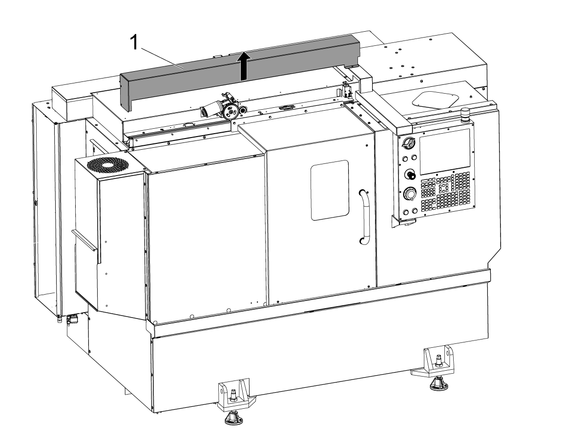
Opriți mașina.

Îndepărtați capacul de protecție al ușii automate [1].

2

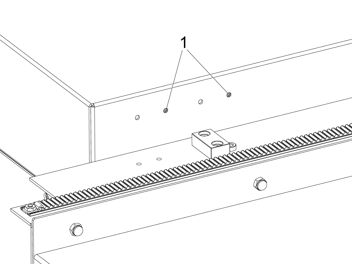
ST-20/25 & DS-20Y/25Y:

Pentru maşini cu orificii pentru consolă de comutare pe panoul acoperişului. Instalați suportul comutatorului în perechea dreaptă de orificii[1] pentru ST-20/25.

3

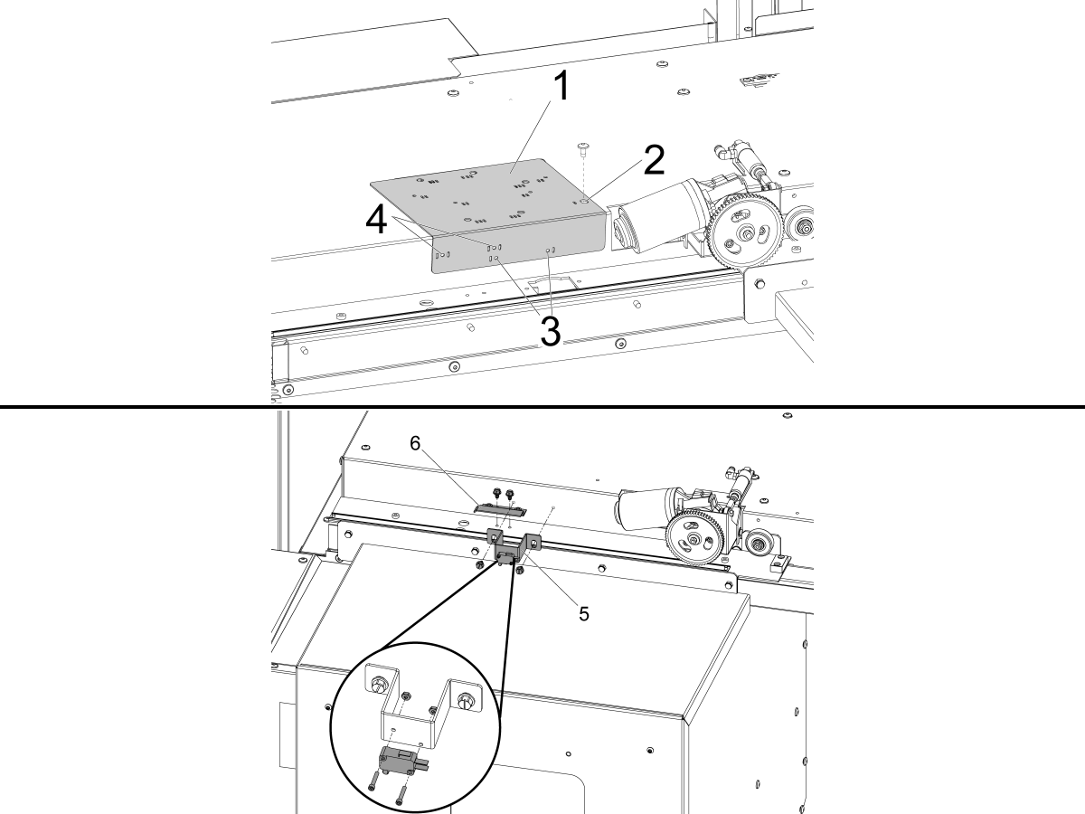
Pentru maşini fără găurile suportului comutatorului pe panoul acoperişului.

Utilizați ghidajul de găurire prevăzut [1] pentru a perfora orificiile de montare pentru DOOR FULLY OPEN comutatorului de stare.

Aliniați orificiul cel mai îndepărtat din partea dreaptă din partea superioară a ghidajului de găurire care este marcat cu o fantă [2] cu orificiul de montare a capacului de protecție al uşii automate din partea stângă a motorului uşii auto şi fixaţi-l cu BHCS.

ST-10/15:

  • Perforați cele două orificii de montare de  Ø 3/16" (4,7 mm) prin ghidajul de găurire, care sunt marcate cu o fantă [3].

ST-20/25 & DS-20Y/25Y:

  • Perforați cele două orificii de montare de  Ø 3/16" (4,7 mm) prin orificiile ghidajului de găurire, care sunt marcate cu două fante pe ambele laturi [4].

Folosind șuruburile autofiletante furnizate, instalați DOOR FULLY OPEN ansamblul de comutare [5] şi DOOR FULLY OPEN indicatorul de declanşare [6].

4

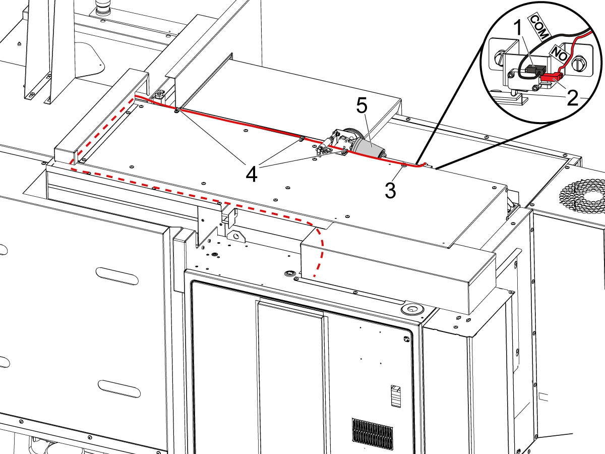
Conectați comutatorul UȘII DESCHISE COMPLET conform etichetării:

  • BLK <COM> la borna superioară [1].
  • RED <NO> la borna din mijloc [2].

Dirijați cablul în compartimentul de comandă așa cum este ilustrat în imagine.

NOTĂ: asigurați-vă că instalați clema magnetică furnizată [3] și clemele cablului [4] pentru a menține cablul în afara razei de mișcare a motorului ușii automate [5].

5

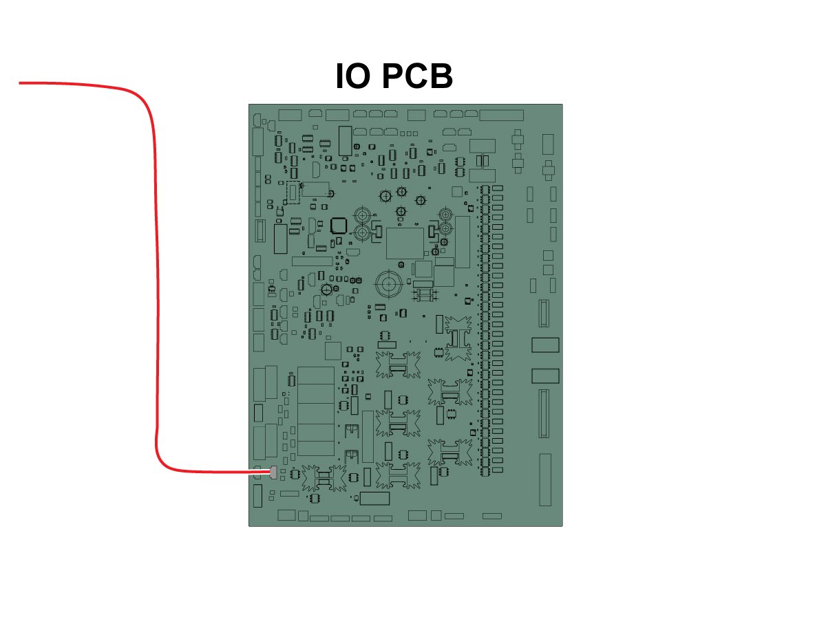
Conectați celălalt capăt al cablului la intrarea deschiderii ușii RRI SIO PCB P27. 

NOTĂ: Asigurați-vă că mașina este OPRITĂ. 

Instalaţi capacul de protecție al uşii automate.

6

  • Ejectorul cu arc al APL este fabricat cu o coadă pentru a se potrivi unui portscule fie de 25 mm, fie de 1”
  • Această unealtă trebuie să accepte un dispozitiv portscule pe capul revolver
  • Dacă mașina este un model ST-10/15, veți avea nevoie de două dispozitive portscule goale pentru a avea spațiu suficient pentru dispozitivul de prindere
  • Programați ca pașii următori să fie la începutul oricărui program pentru a vă asigura că piesa este așezată în mod corespunzător în mandrină:
    • Localizați ejectorul cu arc în fața piesei
    • Deplasaţi axa Z pentru a comprima arcul cu aproximativ 0,50 inci sau 12,7 mm
    • Deschideţi mandrina cu o oprire temporizată de o secundă
    • Închideți mandrina cu o oprire temporizată de o secundă
    • Retrageți capul revolver în cea mai sigură poziție posibilă

Notă: Numărul piesei pentru dispozitivul de împingere cu arc este: 

  • 30-12642 EJECTOR CU ARC.  Suportul de 25 mm sau 1,0” se vinde separat.

Cobot Installation

1

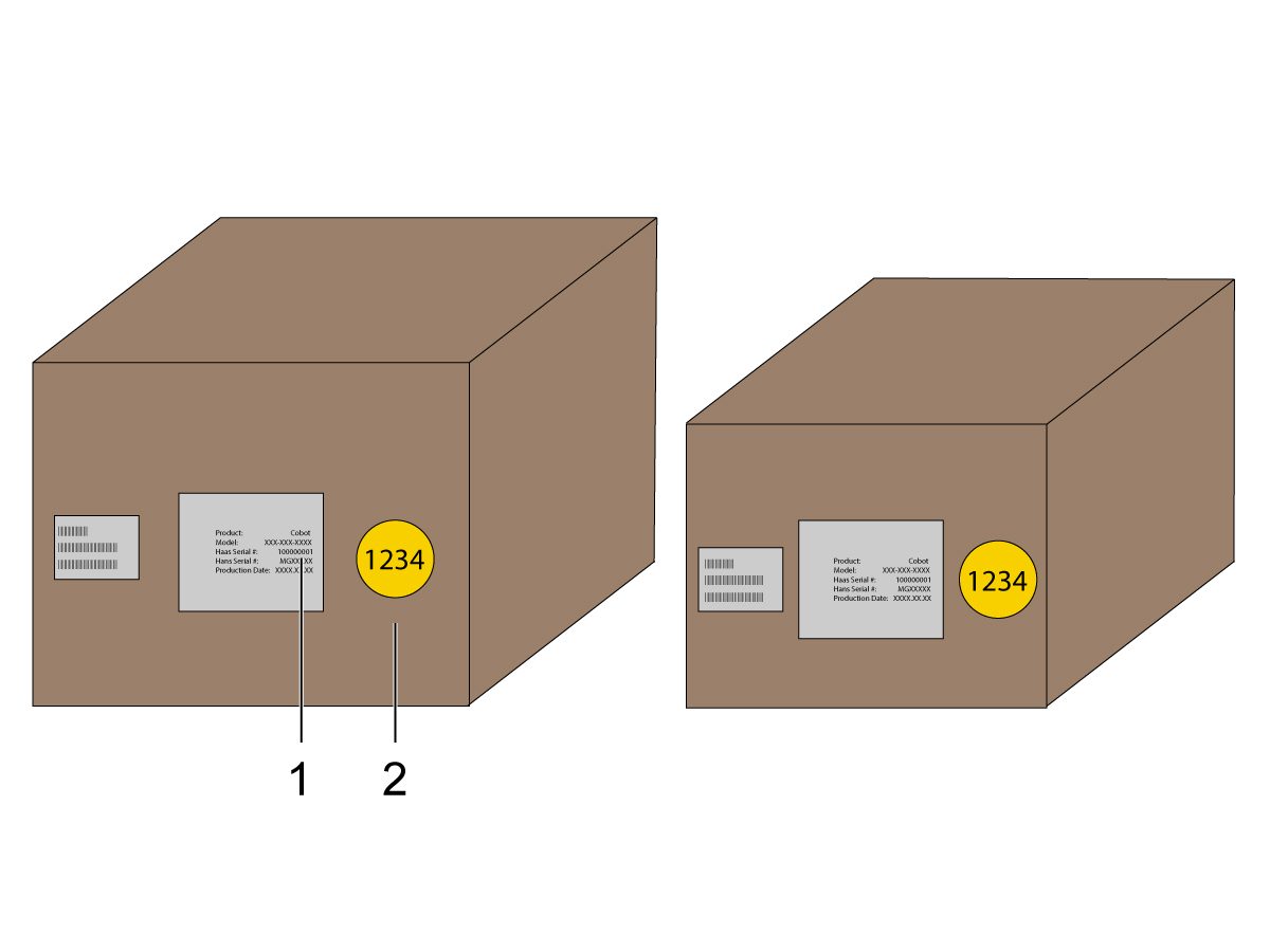
Verificați dacă Cobotul și caseta sa de comandă provin din același set de numere de serie corespondente.

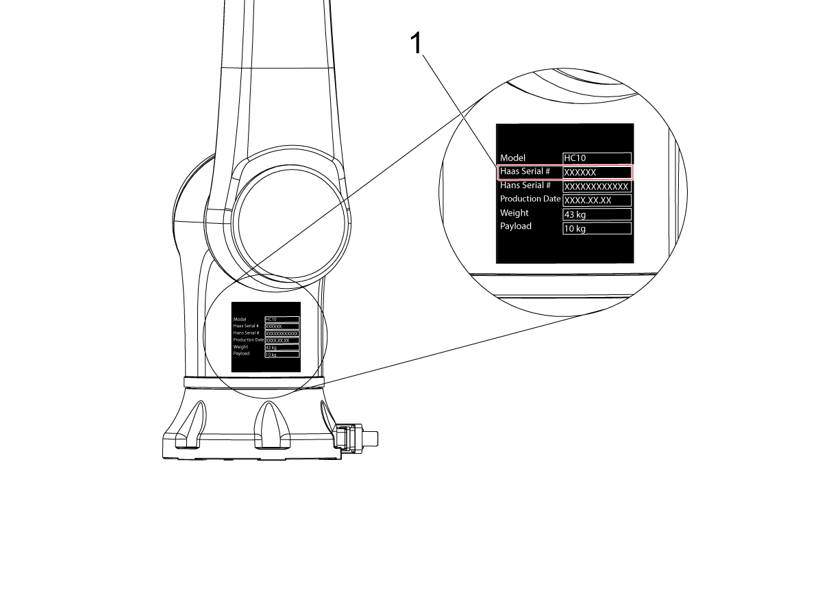
Există un autocolant alb cu numărul de serie Haas [1]. Asigurați-vă că acestea sunt identice pe ambele casete.

Există un autocolant galben cu cerc cu un număr de identificare [2]. Asigurați-vă că acestea sunt identice pe ambele casete.

2

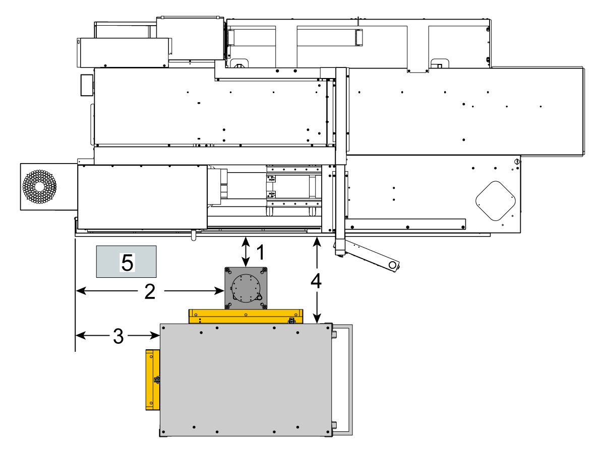
Măsurați această dimensiune de la mantaua mașinii la partea laterală a soclului.

 Notă: Următoarele dimensiuni sunt distanțele recomandate. Poziţia poate varia în funcţie de aplicaţia utilizatorului. 

Utilizați dimensiunile din pașii următori ca referință pentru coboții de încărcare frontală și laterală. 

Se recomandă ca Haas Cobot 10 să fie asociat cu soclul Cobot Haas. Acest soclul este configurat pentru a fi suficient de stabil atunci când este utilizat în conformitate cu dimensiunea pieselor și limitele de greutate definite de Haas. 

3

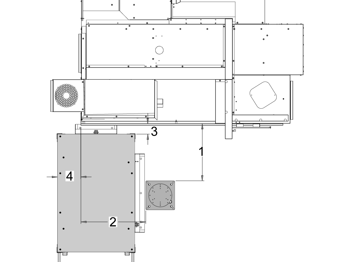
Mașinile ST-10 și ST-15:

Poziționați soclul și masa pentru piese în următoarea locație față de mașină:

Dimensiune Imperial (țoli) Metric (cm)
Partea frontală a mașinii pe partea frontală a soclului [1] 24,5 in 62,2 cm
Partea stângă a mașinii față pe partea stângă a soclului [2] 26,25 in 66,7 cm
Partea frontală a mașinii pe partea frontală a mesei pentru piese [4] 5,5 in 14 cm
Partea stângă a mașinii pe partea stângă a mesei pentru piese [4] 9,75 in 24,7 cm

4

Updated
Mașinile

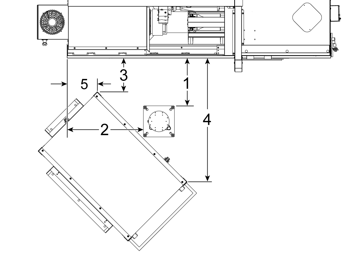
ST-20 și ST-25 & DS-20Y/25Y:

Poziționați soclul și masa pentru piese în următoarea locație față de mașină:

Dimensiune Imperial (țoli) Metric (cm)
Partea frontală a mașinii pe partea frontală a soclului [1] 19,5 in 49,5 cm
Partea stângă a mașinii față pe partea stângă a soclului [2] 28,5 in 72,4 cm
Partea frontală a mașinii în colțul din stânga față al mesei pentru piese [3] 14,5 in 36,8 cm
Partea frontală a mașinii în colțul din dreapta față al mesei pentru piese [4] 71 in 180 cm
Partea stângă a mașinii în colțul din stânga față al mesei pentru piese [5] 10,75 in 27,3 cm

5

Mașinile

ST-30/35 și DS-30Y:

Poziționați soclul, masa pentru piese și cutia de comandă Cobot[5] în următoarea locație față de mașină:

Dimensiune Imperial (țoli) Metric (cm)
Partea frontală a mașinii pe partea frontală a soclului [1] 8,5 in 21,6 cm
Partea stângă a mașinii față pe partea stângă a soclului [2] 42,0 in 106,7 cm
Partea stângă a mașinii pe partea stângă a mesei pentru piese [3] 23,5 in 59,7 cm
Partea frontală a mașinii pe partea frontală a mesei pentru piese [4] 24,0 in 61,0 cm

6

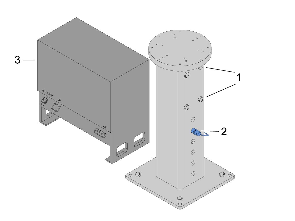
Ancorați soclul în sol. Nivelați soclul folosind o nivelă cu bulă de aer. 

 NOTĂ: Pentru soclul reglabil, setați înălțimea dorită slăbind șuruburile de ajustare [1] și apoi reglând știftul cu cap și gaură [2]. Strângeți din nou șuruburile de reglare [1] înainte de a instala robotul. Așezați o nivelă cu bulă de aer în partea superioară a soclului, în timp ce utilizați cele (x4) șuruburi hexagonale de la bază pentru a seta nivelul în planul X și Y.

Așezați cutia de comandă Cobot [3] direct lângă soclu pentru a asigura o slăbire suficientă a cablurilor. 

7

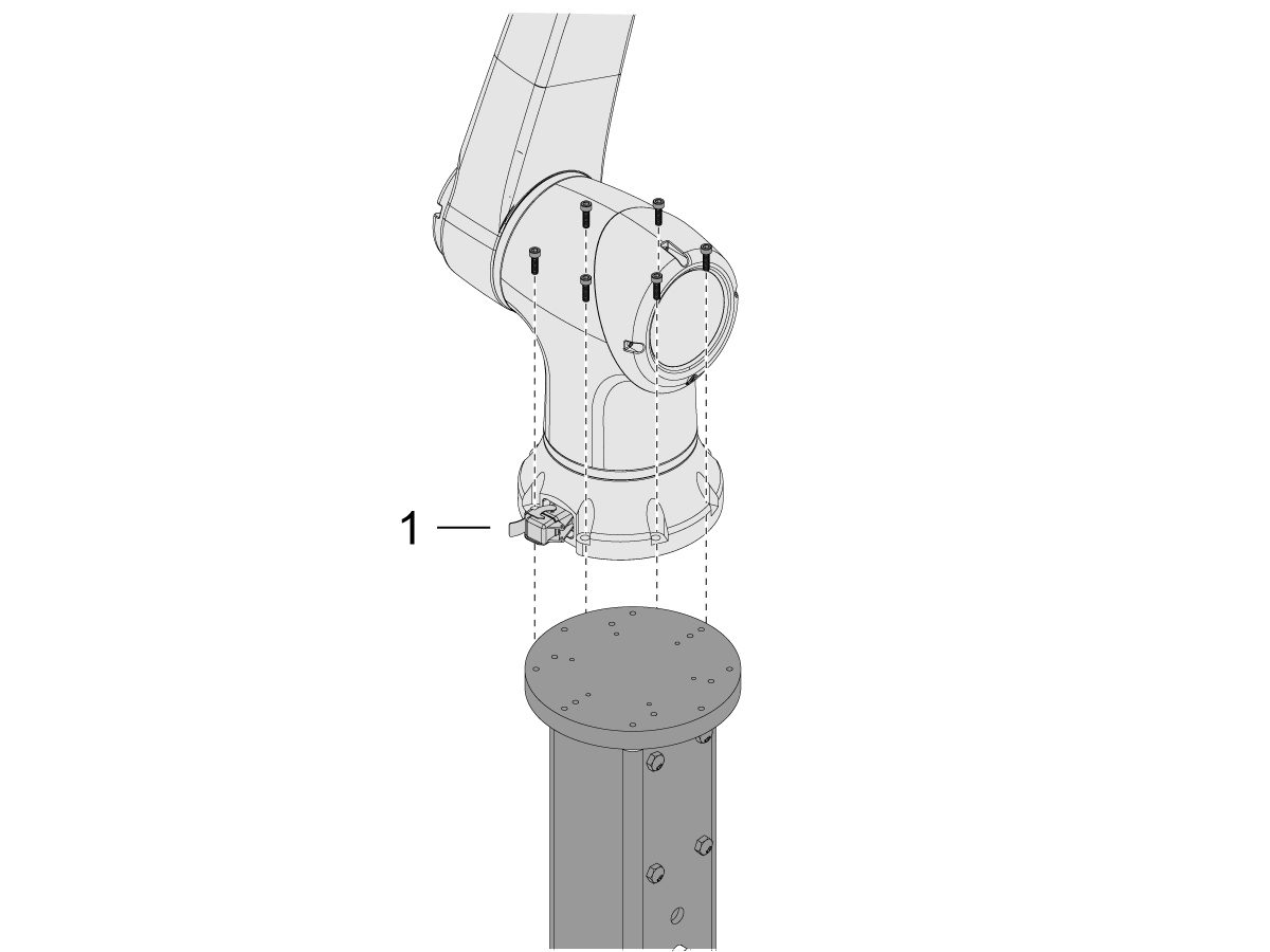
Scoateți robotul din cutia de expediere. 

 NOTĂ: Instalați placa adaptorului între soclu și robot, dacă este necesar. 

Instalați Cobotul deasupra soclului.

 NOTĂ: Asigurați-vă că conectorul cablului cobot [1] este pătrat cu partea frontală a mașinii. 

IMPORTANT: Cobotul are aproximativ 40 lbs și trebuie ridicat cu un dispozitiv care poate ridica în siguranță acea greutate.

Îndepărtați suporturile de ridicare ale cobotului și componentele după montarea robotului.

8

În interiorul ambalajului Cobotului, există o pungă mică [1] umplută cu piese de schimb, inclusiv: 

  • Siguranță
  • Șuruburi (x2)
  • Tastele casetei de comandă

Există o pungă medie [2] umplută cu un conector M12 suplimentar. Acest cablu poate fi utilizat pentru a configura intrările și ieșirile pentru modulul de capăt de intrare/ieșire. 

Există o pungă de dimensiuni mari [3] umplut cu hârtii și un stick USB descărcat cu software-ul Cobot.

Asigurați-vă că păstrați aceste piese de schimb într-un loc sigur pentru utilizare ulterioară. 

Robot Electrical & Air - Installation

 DANGER: Working with the electrical services required for CNC machines is extremely hazardous and can result in serious injury or death.

Before connecting line wires to the CNC:

  • Turn off all power to the machine at the source.
  • Perform a Lockout-Tagout (LOTO) procedure to ensure the power remains off during service.
  • Verify that power has been disconnected by using an AC voltage detector on all incoming lines.

If you are uncertain about how to safely disconnect power or perform LOTO procedures:

  • Do not proceed.
  • Contact qualified personnel or obtain appropriate assistance before continuing.

Failure to follow these precautions may result in electrical shock, equipment damage, or fatal injury.

 Danger: Before beginning any work inside the control cabinet, verify that the High Voltage indicator light on the 320V Power Supply / Vector Drive has been off for a minimum of five (5) minutes. This waiting period ensures that residual voltage has dissipated and reduces the risk of electric shock.

Certain service procedures involve high-risk electrical components and may pose serious injury or fatality hazards. Technicians must not attempt any procedure unless they have a complete understanding of the steps involved and the associated risks.

If there is any uncertainty regarding a procedure, contact your Haas Factory Outlet (HFO) to arrange for a qualified service technician.

1

Connect Interface Box to Haas Machine:

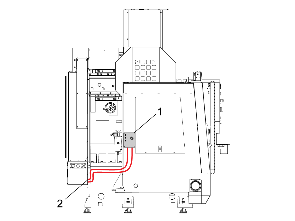
The robot safety devices interface box 32-9018 has magnetic mounts to attach to the machine sheet metal. Mount the interface box [1] as shown in the picture.

Route the interface electrical cables [2] along the enclosure with the magnetic mounts and zipties. Route the cable through the bottom of the electrical cabinet.

NOTE: For information on upgrading the interface box to the Robot Safety Devices Interface Box, refer to the Robot Safety Devices Interface Box - Installation - AD0703. 

2

Connect Interface Box to Haas Control Cabinet:

Connect cable 33-8562C E-STOP terminal block to TB-1B [1] and connect the Setup mode terminal block to TB-3B [1] on the SIO PCB.  

Plug the user relay into K9 and K10 [2].

Verify the jumper is installed on the SIO PCB at JP1.

Connect the pigtail cable labeled P1 SIO to the SIO PCB at P1 [3]

NOTE: If the machine has a Regen Vector Drive, unplug cable 33-0634 FILTER OV TO IOPCB P1 from P1 SIO and plug it into the connector FILTER OV FAULT on cable 33-8562C. If the machine does not have a Regen Vector Drive, do not plug anything into the connector FILTER OV FAULT.

Connect the RJ-45 cable [4] to Ethernet to USB adapter [5] (33-0636).  Connect the USB connector end to the Maincon PCB J8 top port. Add a ferrite filter [6] to the USB adapter.

Mount the 24VDC Power Supply [7] to the left side of the control cabinet and plug into connector labeled 24V PS on cable 33-8562C. Connect cable 33-1281 [8] to the 24VDC Power Supply [7] and plug into P3 on the PSUP PCB. 

3

For MM/SMM CM/CL machines Without XMR

If P3 is occupied by a jumper connected from P3 [10] to P7 [9] on the PSUP PCB, a splitter cable is needed to allow the 24VDC power supply [7] to be connected to the 120VAC connectors on the PSUP. Connect the male connector of the splitter cable to P3 [10] and then connect the jumper from that cable to P7 [9] and also cable 33-1281 [8].

Note: Make sure that the jumper cable is connected where the red lines up with the red from the splitter cable.

4

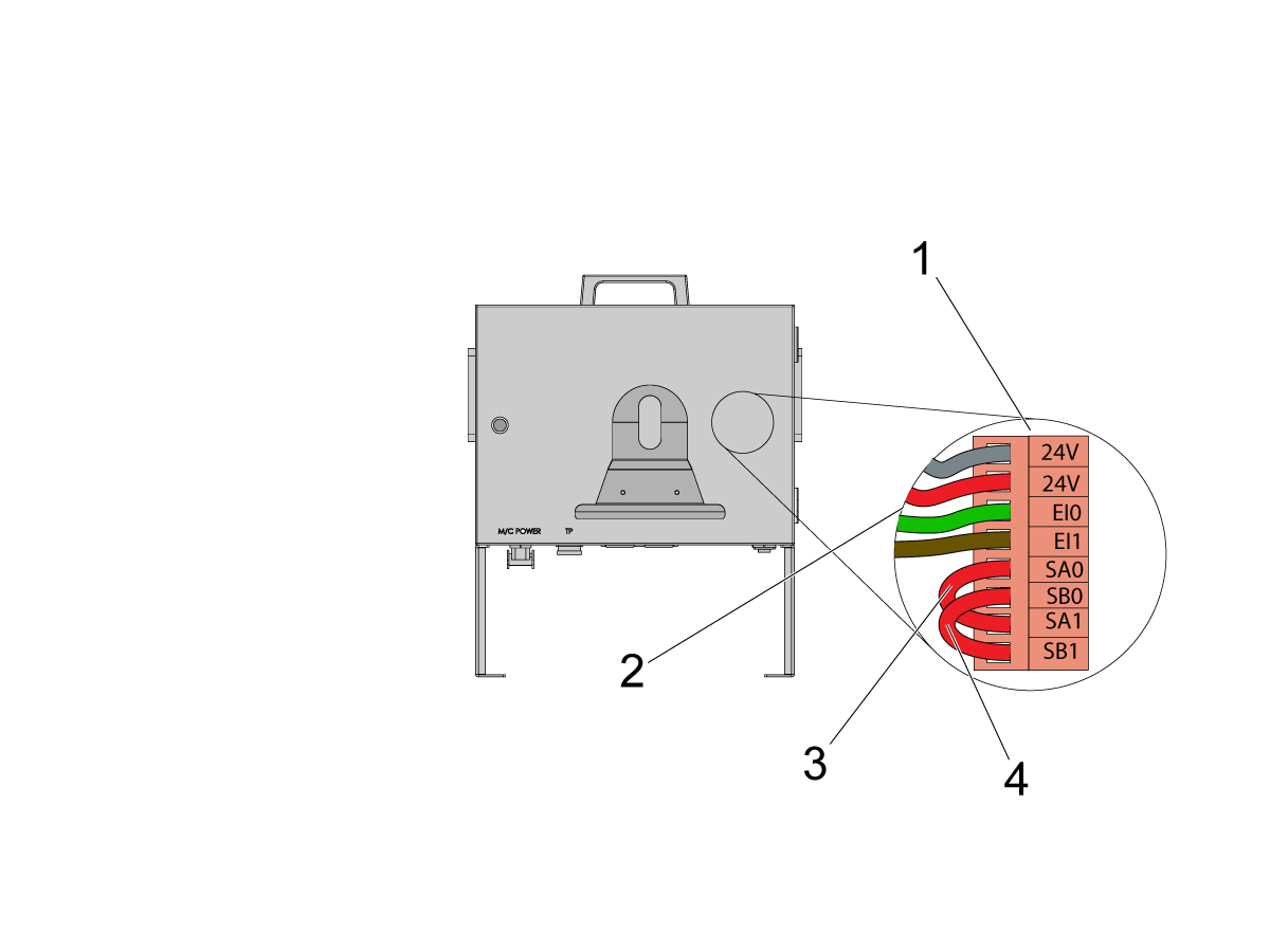
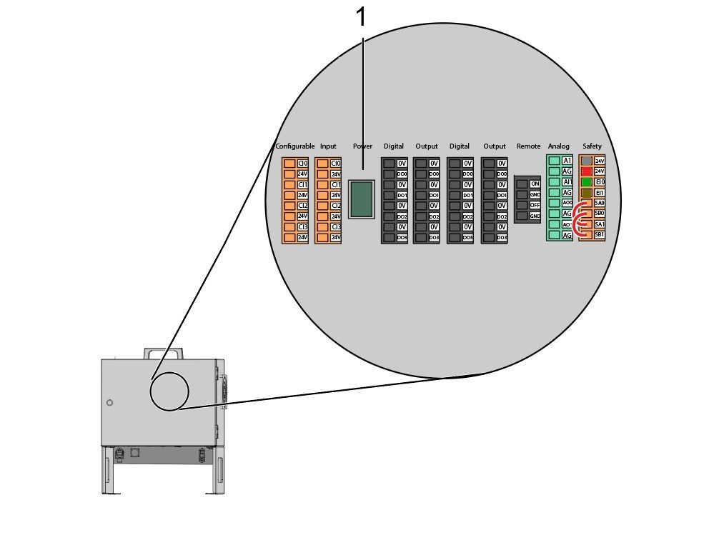
Inside the Cobot control box, install part of the robot signals cable (33-1272 or 33-1351).  To do so, remove the safety connector [1] from the Cobot control box in order to install the different colored wires into their respective location

33-1272 / 33-1351 cables [2] going to safety connector:

  • Gray wire to top 24V
  • Red wire to bottom 24V
  • Green wire to EI0
  • Brown wire to EI1
  • Jumper [3] from SA0 to SA1
  • Jumper  [4] from SB0 to SB1

 NOTE: The rest of the wires from this cable are not used. Put some electrical tape on each wire lead and Ziptie the leftover unused wires. 

5

Important: After installing all the cables from the robot signal cable, make sure that the fuse [1] remains installed at all times to protect the Cobot control box.

6

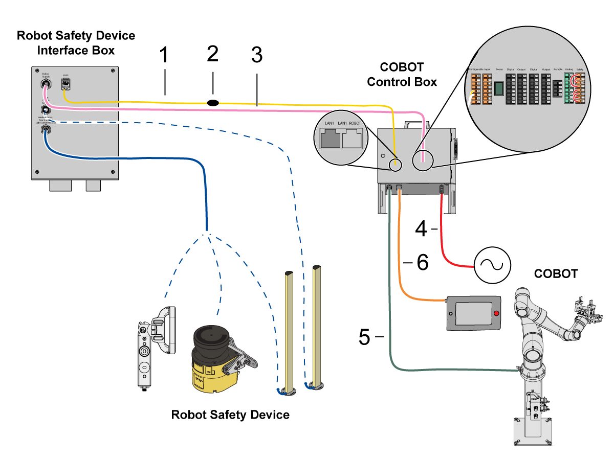
Connect Cobot to the Interface Box:

Connect the RJ45 ethernet cable [1] from the Cobot Control Box to the interface box. Add a ferrite filter [2] to the RJ-45 cable.

Connect the robot signals cable [3] from the Cobot Control Box to the interface box. 

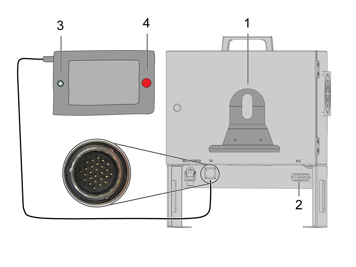
Connect the 120 VAC Cobot Power Cable [4] to the external power source. 

Connect the robot power cable [5] from the control box to the Cobot.

Connect the teach pendant cable [6] from the control box to the teach pendant. 

NOTE: For more information regarding interlock fence, area scanner or light curtain installation, refer to the Robot Safety Device section below.

7

Make sure the Remote Jog Handle is installed onto the machine.

NOTE: For more information on the RJH-XL installation, refer to Remote Job Handle - Touch Large (RJH-XL) - Installation - AD0533. 

8

Steps 7 thru 10 are wiring and hose routing instructions for the pneumatic grippers. Refer to the grippers installation section lower on this page for the mechanical installation.

Install the dual air solenoid assembly on to the side of the pedestal while giving the airlines enough slack. Make sure it's in a position where it will not be in the way. Route the airline [1] under the machine back towards the CALM cabinet as shown.

9

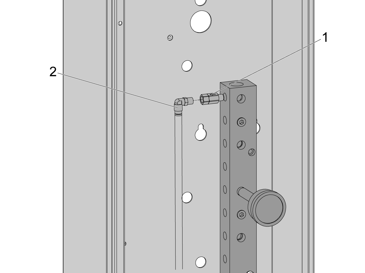
Inside the CALM cabinet, remove a plug from one of the CALM manifold ports and install the check valve [1] (58-1863) onto the port's fitting. Route the input airline [2] from the dual air solenoid assembly (from previous step) into the CALM cabinet and connect the airline to the check valve.

Turn the machine air supply ON.

10

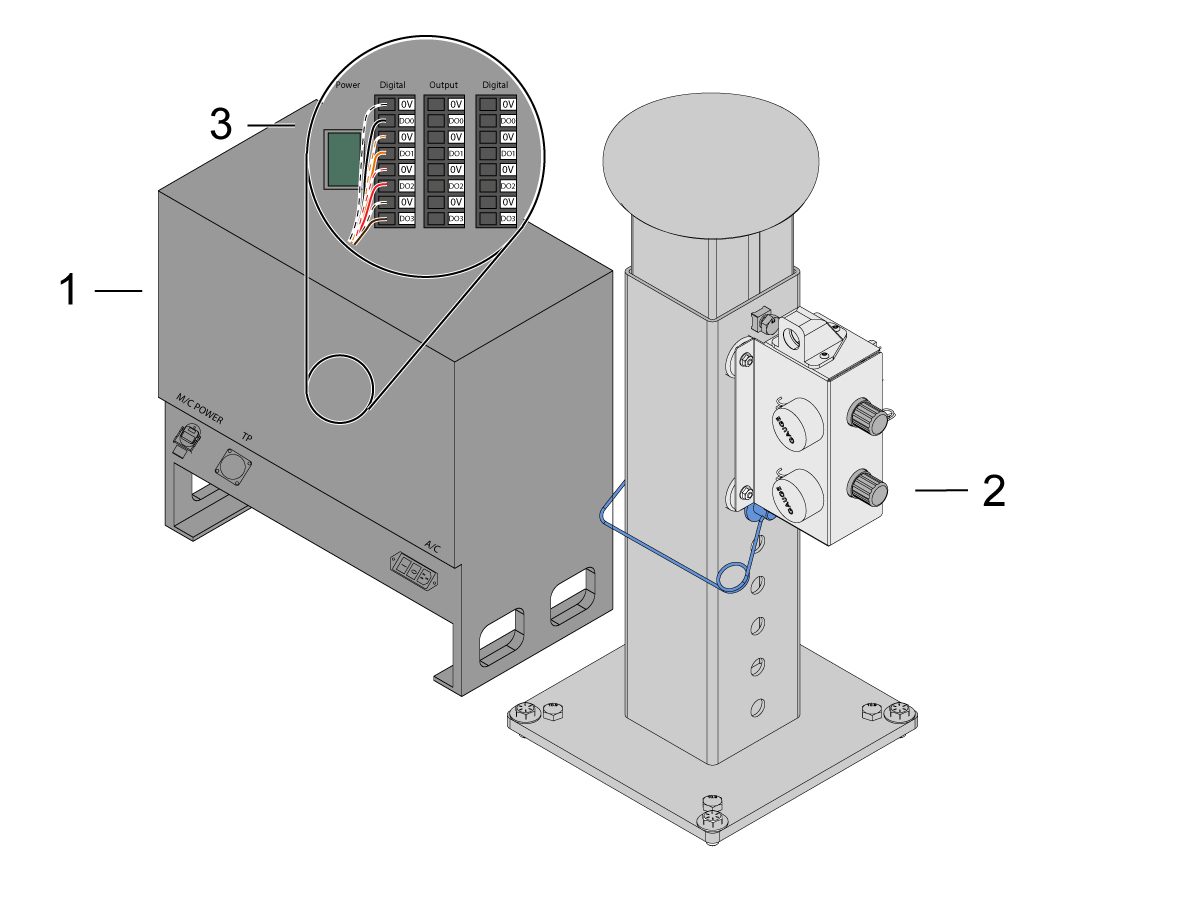
Make sure to power OFF the control box [1].

Connect the solenoid cable from the dual air solenoid assembly [2] into the Digital Output on the Cobot control box [1]. Remove the connector from Cobot control box.

11

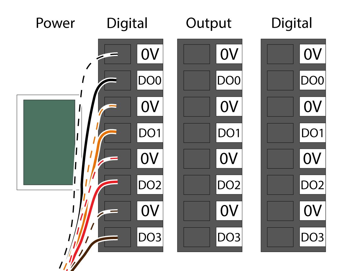
Connect the gripper solenoid power cable (33-1276 / 33-1341) to the Digital Output terminal inside the control box. Install the different colored wires into their respective location:

  • Black/white cable into 0V
  • Black cable into DO0
  • Orange/white cable into 0V
  • Orange cable into DO1
  • Red/white cable into 0V
  • Red cable into DO2
  • Brown/white cable into 0V
  • Brown cable into DO3

Power ON the control box.

Robot Safety Device

IMPORTANT: NU UTILIZAȚI ROBOTUL DECÂT DACĂ AȚI CONFIGURAT ȘI TESTAT CORESPUNZĂTOR FUNCȚIONAREA DISPOZITIVULUI DE SIGURANȚĂ.

Barieră luminoasă:

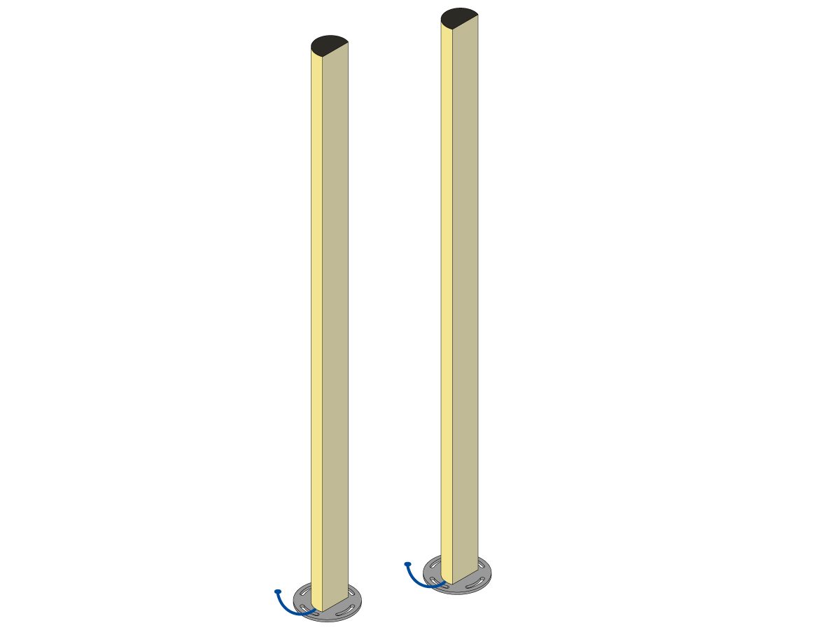
Pachetele Cobot sunt livrate cu emițătorul și receptorul barierei luminoase ca dispozitiv de siguranță implicit. Urmați procedura de mai jos pentru instalare: 

Instalarea barierei luminoase

NOTĂ: Dacă a fost comandat kitul pentru zona de scanare sau HC10 mașină pregătită, va exista și un receptor și emițător pentru bariera luminoasă 1M. Acestea sunt livrate cu toți Coboții. 

Parapetul robotului:

Dacă mașina a fost echipată cu opțiunea parapet, ansamblul parapetului robotului și al interblocării ușii trebuie instalat pe mașină. Urmați procedura de mai jos pentru instalare:

Instalarea parapetului robotului

După instalarea parapetului, instalați panoul parapetului între mașină și parapetul robotului.

Scaner de zonă:

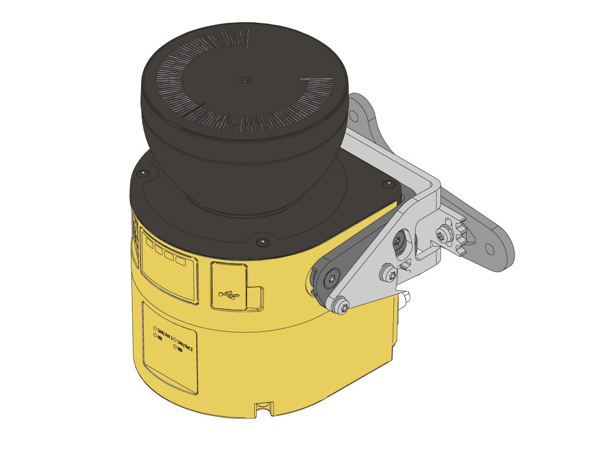
Dacă mașină a fost echipată cu opțiunea scaner de zonă, acesta trebuie instalat în zonă și configurat. Urmați procedura de mai jos pentru instalare: 

Instalarea cititorului de zonă

First Power-UP

1

Power ON the Haas machine. 

Power ON the Cobot by flipping the power switch [1].

Power ON the Cobot teach pendant by pressing the circle [2]. 

Make sure that E-STOP [3] on the Cobot teach pendant is released. 

In order to change the language, click on the language drop down menu. Choose EN for English. To confirm this setting change, the Cobot teach pendant will have a popup asking to insert the username & password. 

Enter "admin" for both the username and password. 

2

Note: The Cobot teach pendant will have a popup asking to insert the username & password. To sign into the teach pendant use these credentials:

  • Username = admin
  • Password = admin

Go into Run mode. Press Enable. 

Go into Jog mode [1].

Move each joint to it's zero location with the Move Zero buttons [2]. 

3

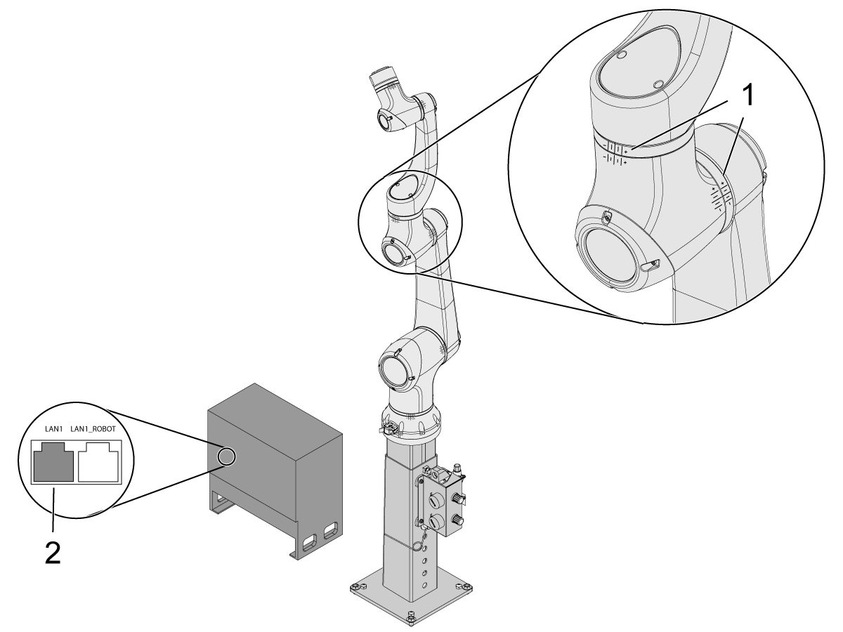
Once the robot is in it's zero location, verify that the hash lines [1] align on either side of each joint on the Cobot. 

 IMPORTANT: If any joint hash lines [1] do not align, jog the specific joint accordingly until all the hash lines [1] do align. This position will be set in the next step as the new Cobot zero position.  

Connect an ethernet cable [2] from the Cobot control box into a computer.

On the computer, change the adapter setting to enable the ethernet port. 

Note: See next steps for help on changing adapter settings.

4

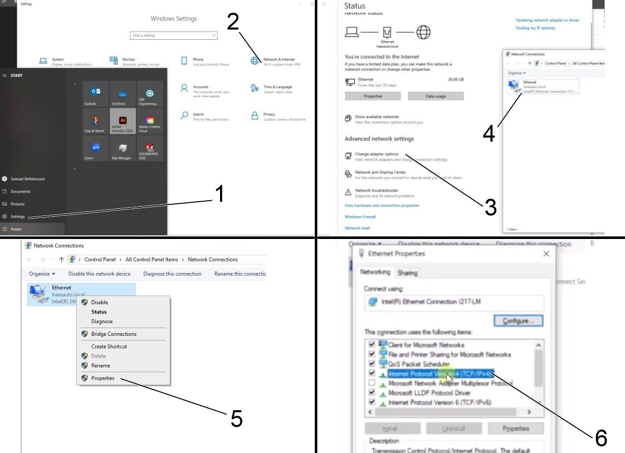
To change the adapter settings, open the settings page [1] on the computer, then click on Network & Internet [2] which will bring up the network status page.

Click on Change adapter options [3] then right click on Ethernet [4] and open up the properties window [5]. From there select the Internet Protocol Version 4 (TCP/IPv4) [6] option and click Ok. 


5

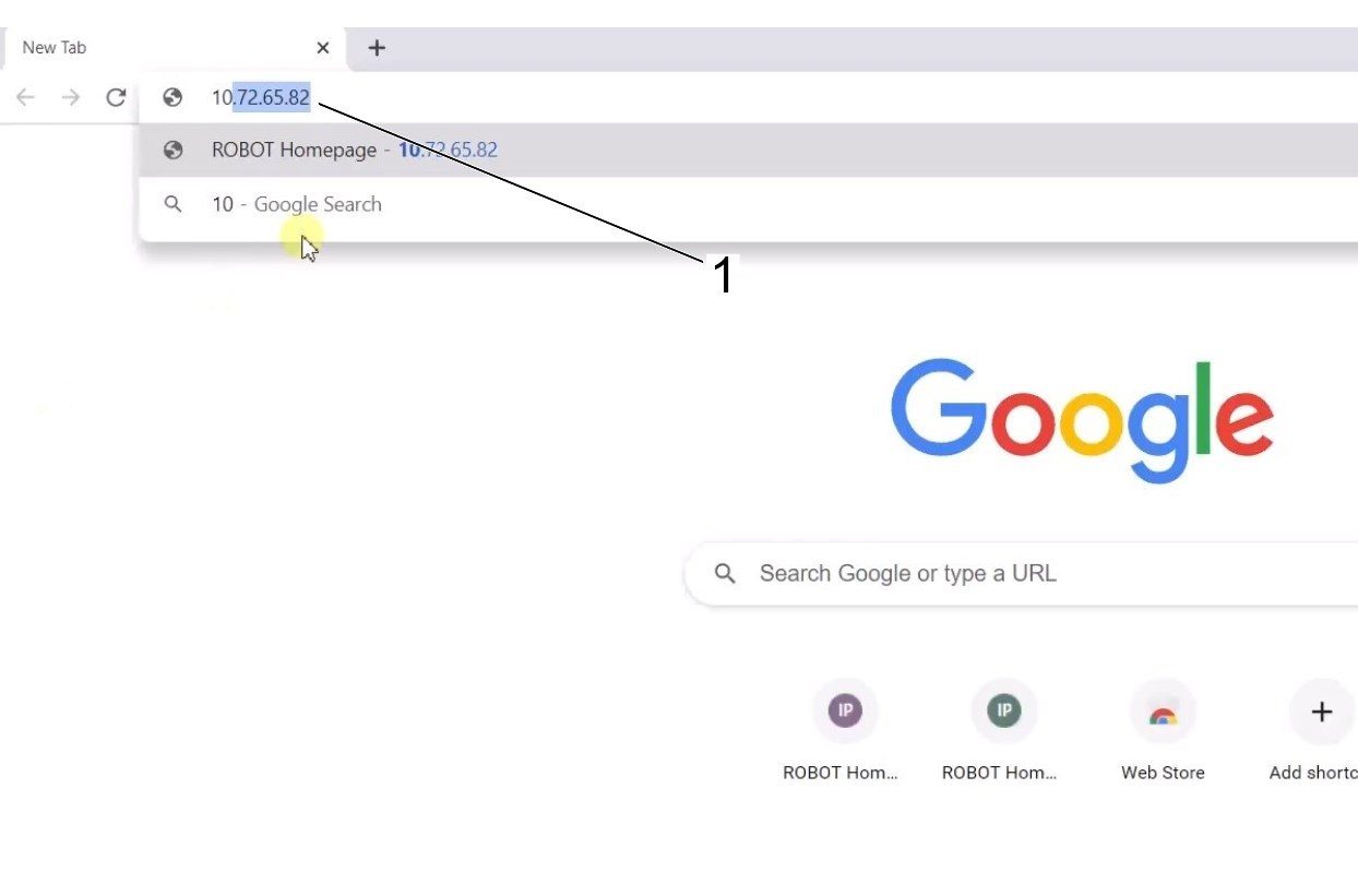
The ethernet settings will now be correct. Open a web browser window and type in the IP address of the Cobot[1]. 

Note: This is the same process as connecting a laptop to an HRP-1/2/3. For more information on connecting to the Cobot via ethernet, refer to the video on the HRP-Troubleshooting page that is in the Connect & Jog Haas Robot section. 

6

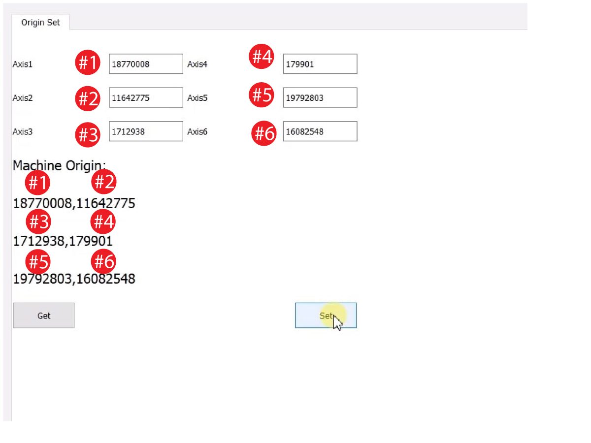
Download HRTool through HBC. On the Service section of HBC, navigate to Utilities > Documents and Software > 01 Control Software > 01 Next Generation Control > 10 Cobot Software > HRTool.zip.

Unzip the folder and navigate to HRToolsMaind.exe.

Insert the Cobot IP address found under the Systems tab.  Click Set. 

Go to the Config tab on HRTool.

Click "get" to see the actual vs. theoretical encoder values. 

Click "set" to set the theoretical to the actual encoder values. This step sets the Cobot's current position as it's new home position. 

7

Make sure that each joint's actual and theoretical encoder values match. 

NOTE: If the valuyes do not match, press "Set" again. 

8

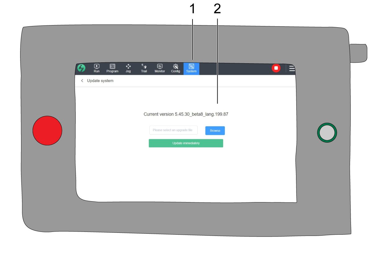
On the teach pendant, navigate to System [1] and then Update System. 

Confirm the Cobot firmware [2] is either:

  • HR5.51H.16.beta.20231213.zip
  • HR6.4.9.tmp.20240919.zip

NOTE: Firmware version HR6.4.9.tmp.20240919.zip is compatible with all size cobots.

Refer to the Haas Cobot - Maintenance chapter for the firmware update procedure. 

9

Turn on the Haas CNC.

Zero Return all Axes.

Insert Service USB key.  Go into Service mode.

Go to Parameters> Factory tab.  Change the following:

  • 1278 [1278:] Robot Ready E-Stop Enabled to TRUE
  • 2191 [694:] LIGHT CUTAIN TYPE to LC_TYPE_1
  • 2194 [:] Enable Front Door Fully Open Switch to TRUE

Note: Machines with Software Version 100.20.000.1010 or higher will need to change the following parameter:

  • 2192 [:] Light Curtain Trigger Threshold to 0

Press [SETTING].

Set the Settings:

  • 372 Parts Loader Type to 3: Robot.
  • 376 Light Curtain Enabled to On


10

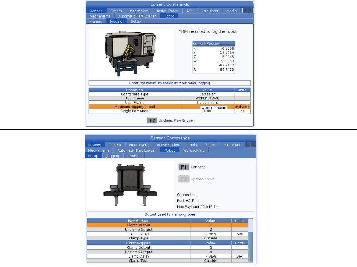
On the Haas pendant, press [CURRENT COMMANDS].

Go to Devices>Robot>Jogging tab. Change the following:

  • Maximum Jogging Speed to 7.9 inch/sec

 Note: The jogging increments on the RJH are a percentage of this max speed value. In order to decrease the distance the robot travels of each jog wheel tick, you need to change your Maximum Jogging Speed to a lower value.

Go to the Setup tab. Change the following:

  • Max Robot Speed to 118 in/sec (2000 mm/sec). 
  • Enter the Net Mass of the gripper. Refer to the layout drawings on our website (Single Gripper layout drawing OR Dual Gripper layout drawing) to get the correct value for this setting
WARNING: Setting this value incorrectly can cause the Robot Arm to not move correctly. 
 
  • Number of Grippers to the number of grippers.
  • Raw Gripper Clamp Output to 1.
  • Raw Gripper Unclamp Output to 2.
  • Raw Gripper Clamp Delay to the clamp/unclamp duration in sec.
  • Raw Gripper Clamp Type to OD/ID.
  • Finish Gripper Clamp Output to 3.
  • Finish Gripper Unclamp Output to 4.
  • Finish Gripper Clamp Delay to the clamp/unclamp duration in sec.
  • Raw Gripper Clamp Type to OD/ID.

Security Risk Level

1

IMPORTANT: Make sure to perform an appropriate risk-assessment and met all appropriate safety requirements. 

2

Based off the risk assessment, set the appropriate security risk level on the Cobot teach pendant. Navigate to Config > General Restrictions and tap of the desired security risk level [1] from 0 - 5.

Use the  "admin" code in the safety verification to change the security level.

NOTE: When the security risk level is lower, the robot will have a lower maximum speed, force, etc. When the security risk level is higher, the robot will have a higher maximum speed, force, etc. 

This security risk level will calculate the maximum allowable force, speed, power, momentum, elbow speed and elbow force [2] that the Cobot will withstand before Alarm 9150.10017 Collison Stop Error is triggered. 

IMPORTANT: The robot's programmed speed cannot be greater than the allowable speed from the security risk level. 

NOTE: For more information regarding alarms, refer to the Haas Cobot - Troubleshooting Guide. 

Activation

1

Download and load the configuration files by logging into the HAAS SERVICE PORTAL.

Download the safety automation option front/side configuration files.

Load the option configuration patch file to the control. Refer to the NEXT GENERATION CONTROL - CONFIGURATION FILE - DOWNLOAD/LOAD procedure.

2

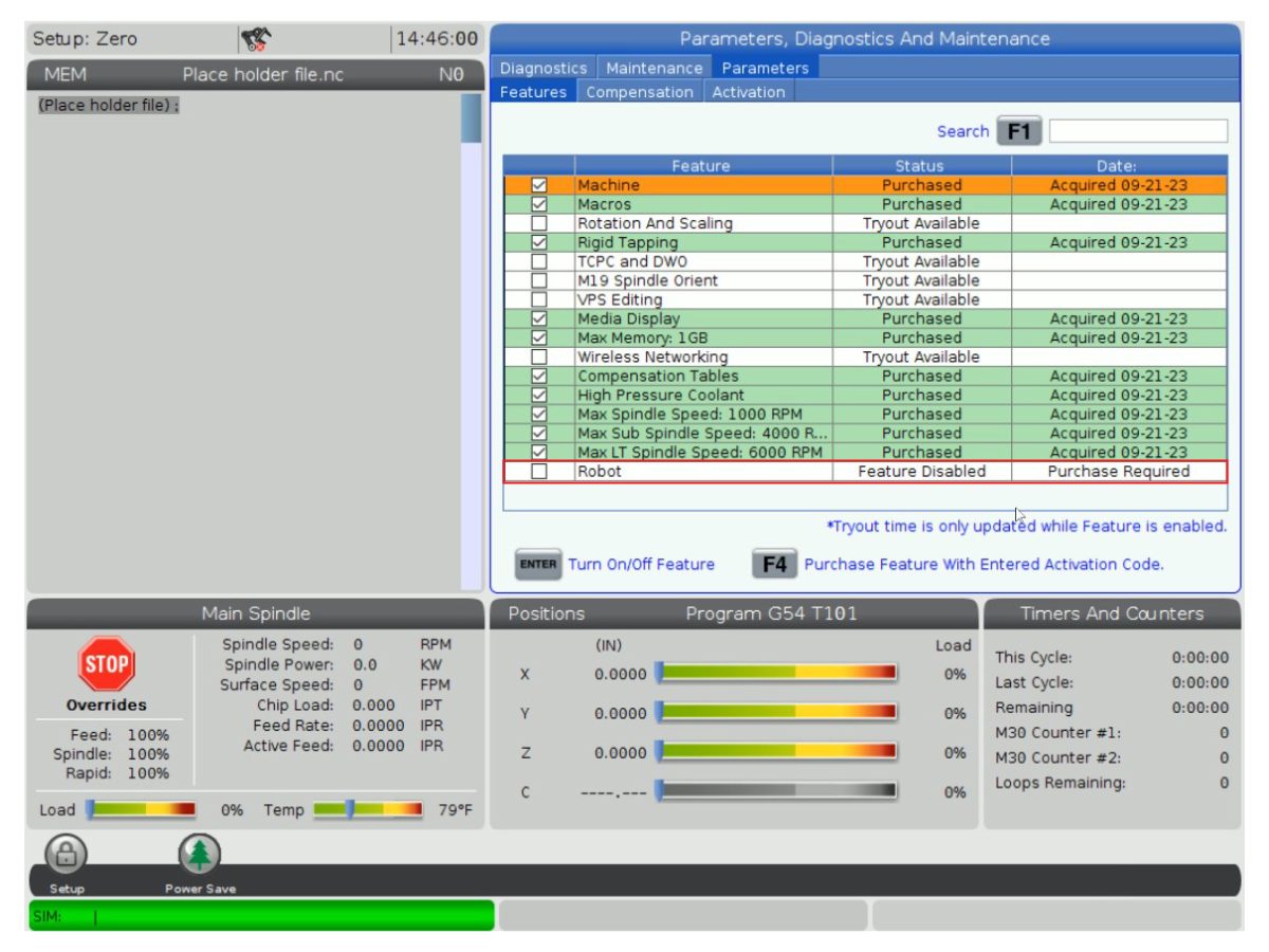
Go to Parameters > Features > Robot to verify that the robot feature has appeared on the bottom.

3

Press [CURRENT COMMANDS].

Go to Devices>Robot>Setup tab [1].

Press [E-Stop].

Press [F1] to connect the robot[2].

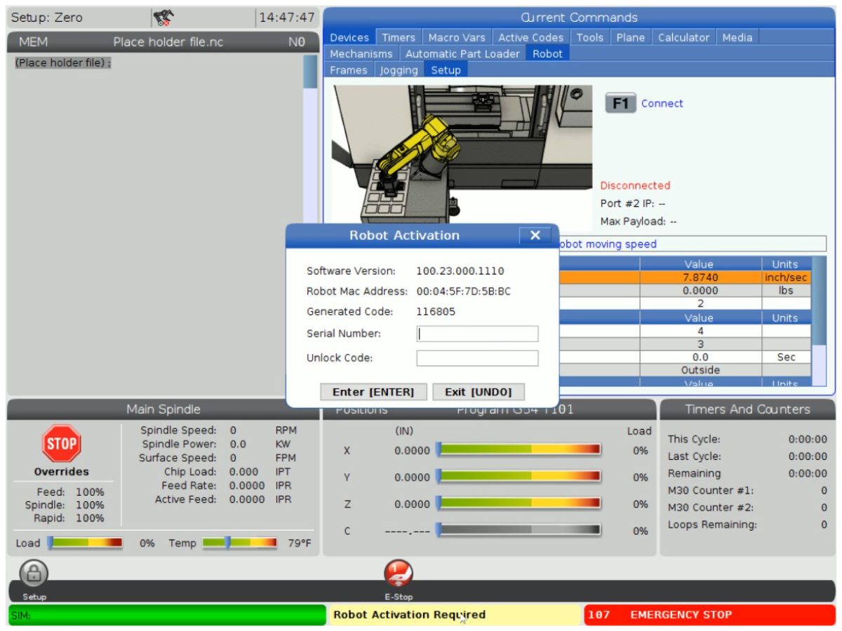
The first time connecting a robot to a machine, the robot feature will need to be unlocked. This popup shows the machine's current software version, robot mac address and a generated code. Enter this information into HBC in order to receive the unlock code.

4

On HBC, go to the Service tab [1].

On the left hand side of the screen, click on Activations [2], and then select Cobot Installation [3] to begin the process to the get the Cobot unlock code.

The first step is to enter the Machine Serial Number [4] and the Cobot Serial Number [5] in the fields on HBC.

Once you have entered the correct information, press Next [6] in the bottom right corner and continue through the steps until you receive the unlock code.

Note: Make sure you are on the Cobot Installation tab [3] and not the Robot Installation tab. The Robot Installation is only used for the Haas Robot Packages. Using the Robot Installation for the Haas Cobots will result in an invalid unlock code.

5

Enter the Cobot's Haas Serial Number[1] and the unlock code to connect the robot to the machine. 

 Note: This step can only be completed by a HFO Service Technician.

 Note: The machine needs to be activated before the Cobot is activated. Follow the Machine Activation / Time Extension - NGC procedure.

When the robot has connected with the machine, a yellow message saying Robot Activation Successful should appear at the bottom of the Haas screen.

6

Release the [E-STOP] and press RESET to clear the alarms. 

Press the [HANDLE JOG] button. 

Press the [CURRENT COMMANDS]  and go to Devices > Robot > Jogging tab.

 Note: The robot in setup mode can only be handle jogged while the F2 button the RJH is pressed. See Setup/Run mode section below.

On the Remote Handle Jog Touch press the Joint button to go into the Joints Coordinates.

Move the robot to an accessible location to install the grippers.

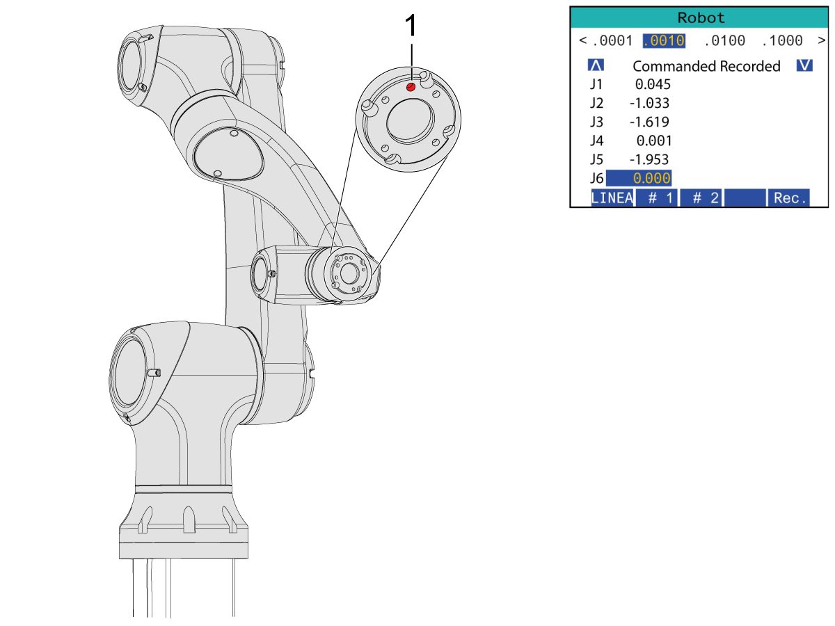
Jog J6 to 0.0000 position. The location hole should be centered on top.

Note: Press [E-STOP] before working on the robot.

Gripper Installation

1

Turn off the machine air by turning the valve in the Air/Lube cabinet and pull the pressure relief valve to release the air in the system.

2

For the Dual Action Gripper:

There are two versions of the dual-action grippers for this section, both of which have the same installation process.

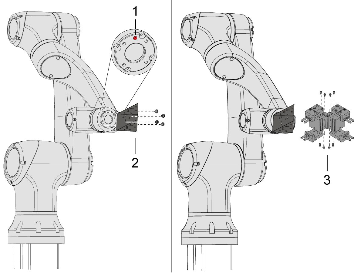
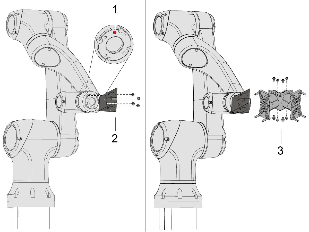
Jog the robot so that the location hole [1] is centered on top.

Install the adapter plate [2] onto the end of the robot arm.

Install the dual gripper assembly [3] onto the adapter plate [2].

NOTE: Make sure to install Gripper 1 (which has the orange and purple zip ties) onto the Gripper 1 adapter plate section. 

3

For the Angled Single Action Gripper:

Jog the robot so that the location hole [1] should be centered on top.

Install the angle adapter plate [2] to the end of the robot arm.

Install the single gripper assembly [3] onto the angle adapter plate [2]. 

4

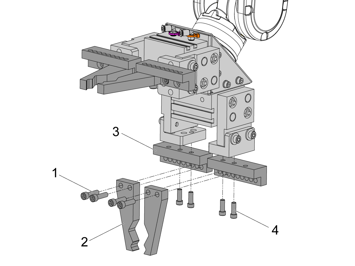
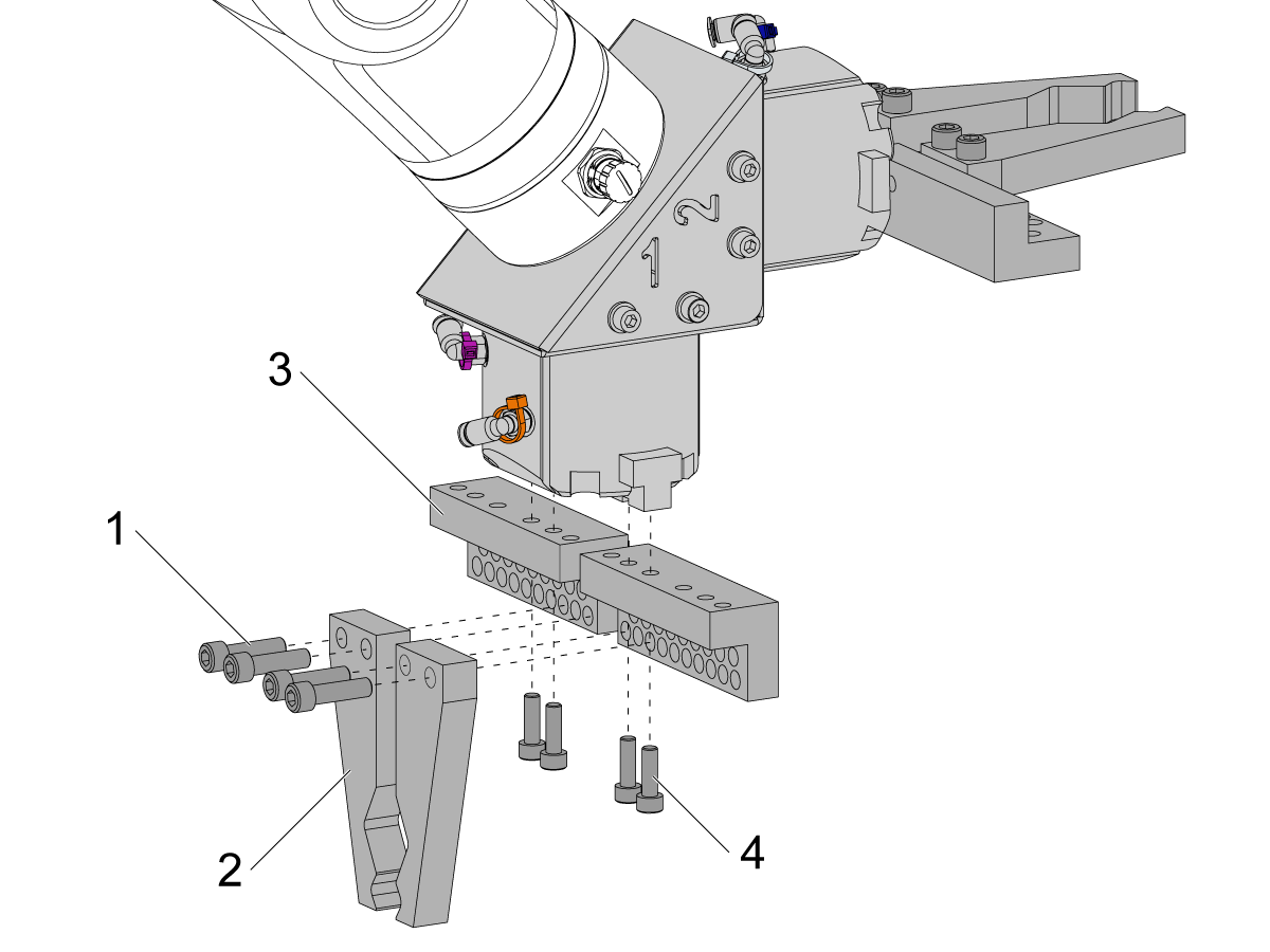
To install the bar gripper fingers, remove the slug gripper plates from the gripper bodies.

Install the Bar Gripper Bolt Plates [3] with (x8) SHCS M6 screws [4]. Torque to 10 ft-lbs.

Install the Bar Gripper Fingers [2] with (x8) SHCS 1/4-20 [1]. Torque to 13 ft-lbs.

5

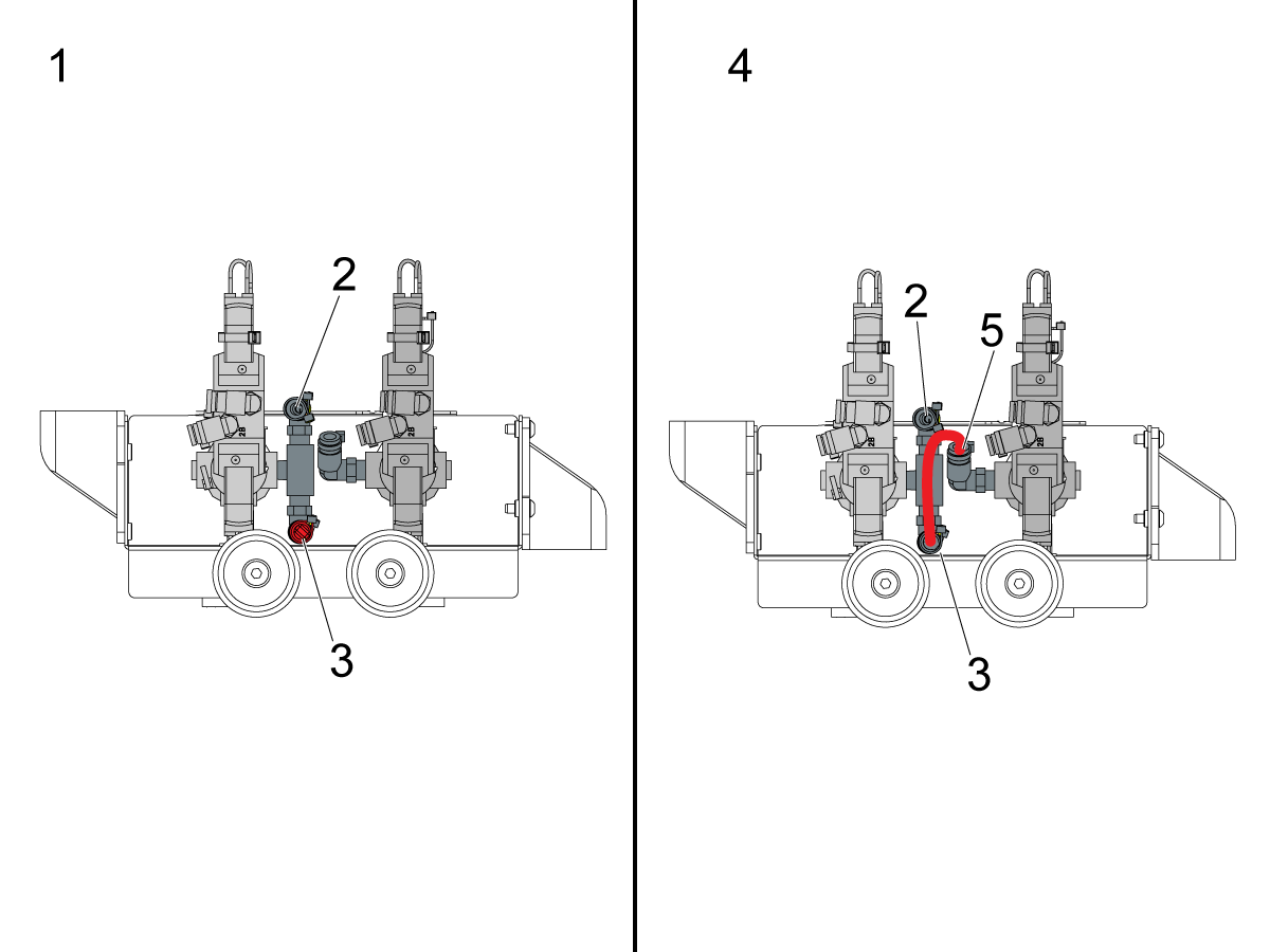
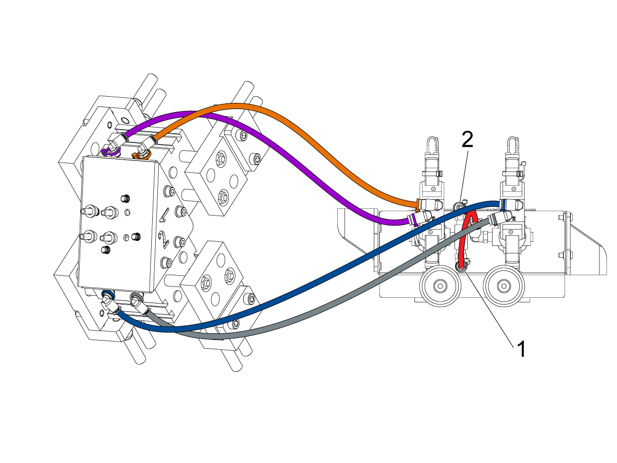
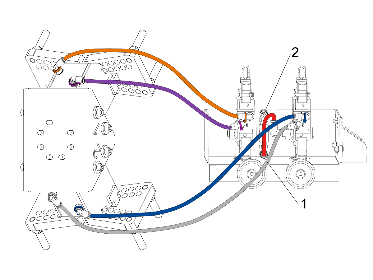
Configure the dual air solenoid assembly used for pneumatic grippers depending on single [1] or dual [2] gripper configuration. 

For single grippers [1], connect the incoming air to the to the fitting [2] and keep the plug in the other end of the fitting [3] as shown in the image.

For dual grippers [4], remove the plug in the fitting [3] and attach a small air hose to the second solenoid [5]. Then connect the incoming air hose to the fitting [2] so that both solenoids are receiving air.

6

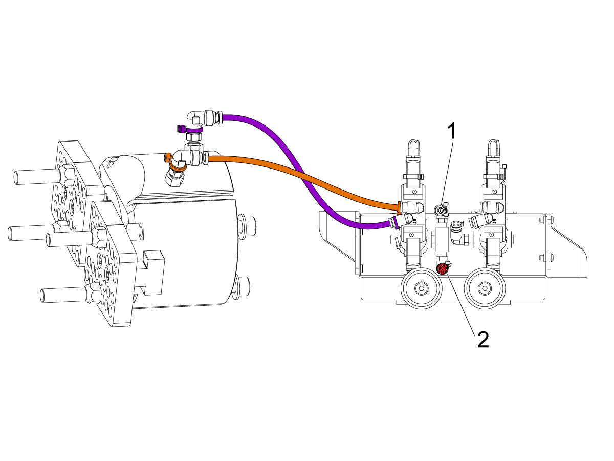
For the Single Gripper:

Route the (x2) air lines from the gripper to the same color coded fitting on the dual air solenoid assembly. 

Secure the air lines by wrapping them in cable conduit. Use the velcro straps to attach the cable conduit to the Cobot. Make sure there is enough slack so that cables aren't strained when Cobot is fully extended.

Insert the input air hose to the used solenoid's fitting [1]. 

Make sure the plug is installed onto the unused solenoid's fitting [2]. 

7

For the Dual Gripper:

Route the (x2) air lines from gripper #1 to the same color coded fitting on the dual air solenoid assembly. 

Route the (x2) air lines from gripper #2 to the same color coded fitting on the dual air solenoid assembly. 

Secure the air lines by wrapping them in cable conduit. Use the velcro straps to attach the cable conduit to the Cobot. Make sure there is enough slack so that cables aren't strained when Cobot is fully extended.

Insert the short airline [1] connecting the first solenoid with the second. 

Insert the input air hose to the fitting [2]. 

Parts Table Assembly

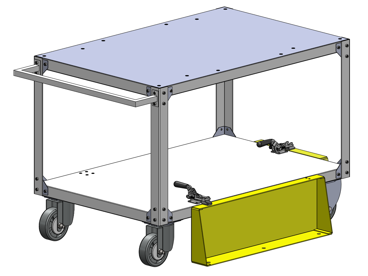
If the parts table option was ordered, follow the procedure below for assembly instructions:

Haas Robot - Parts Table Assembly

NOTE: If HC10 MACHINE READY KIT was purchased, there is no need to install the wheels if mounting the parts table directly into the wooden pallet. 

Verification

Test the E-stop:

  • Press each E-STOP button located on the Haas Pendant, RJH-XL, and Cobot Teach Pendant. Make sure the machine generates 107 EMERGENCY STOP alarm.  If the E-STOP button does not generate a 107 EMERGENCY STOP alarm verify the wiring. Load the latest configuration files to enable the RJH-XL.

Test the Robot Safety Device:

Make sure that there is an E-STOP or light curtain triggered icon on the Haas pendant when the robot safety device is triggered. 

  • Fence - Insert the key into the interlock, verify that the two red LED lights in the front of the interlock are OFF. Remove the key from the interlock, verify that the two red LED lights are ON. 
  • Area Scanner - Step inside the protective field, verify that the red LED lights up on the area scanner. Step outside the protective field, verify that the green LED lights up.
  • Light Curtain - Interfere the light curtain beams, verify that the light curtain triggered icon appears on the Haas pendant. Press [RESET]. Step outside of the light curtain beams, verify no icon appears on the Haas pendant. 

NOTE: If the light curtain triggered icon does not show, verify wiring, alignment and factory setting: 2191 [694:] LIGHT CURTAIN TYPE is set to LC_TYPE_1.

Test the Operation of the Grippers:

  • Verify that both grippers clamp and unclamp correctly.
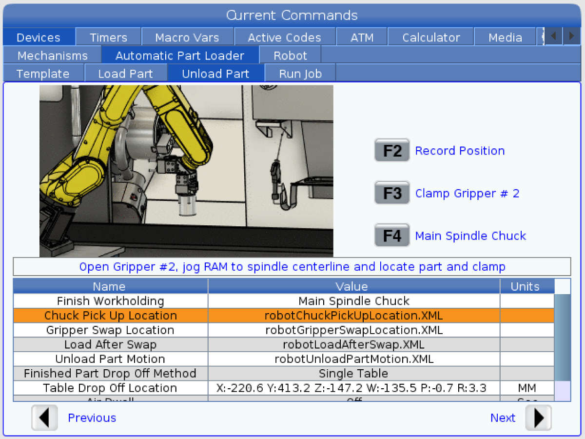
  • Press the [CURRENT COMMANDS]  and go to Devices > Robot > Jogging tab.
  • Press [F2] to clamp/unclamp the Finish Gripper.
  • Press [F3] to clamp/unclamp the Raw Gripper.

Test the Remote Jog Handle:

  • Undock the Remote Jog Handle
  • Press the [HANDLE JOG] button. 
  • Press the [CURRENT COMMANDS]  and go to Devices > Robot > Jogging tab.
  • On the Remote Handle Jog press the Joint button to go into the Joints Coordinates.
  • Move the robot to a safe location.

IMPORTANT: If a yellow warning message appears saying "Please activate Light Curtain or Cell Safe" while trying to job the robot, verify the safety parameter was applied by re-uploading the configuration files from HBC. 

Verify Safe / Run Mode Operation

All Haas CNC machines are equipped with a key switch on the side of the control pendant to lock and unlock setup mode. The robot will have the following behaviors depending on what mode is selected. 

  • When the Haas control is in Run mode, mode 1, triggering the robot safety device stops all motion. This motion can not be started until the robot safety device is no longer triggered.
  • When the Haas control is in Set up mode, mode 2, speed limited motion such as jogging an axis of the robot can be performed in order to program a robot's path of motion, pick up position, set a robot's tool center point, (an offset), load and pick up parts from the spindle or part holder in the machine, etc. The programmed path will also be able to be run slowly to prove out the programmed path of the robot. The robot in setup mode can only be handle jogged while the F2 button the RJH is pressed.

Haas Robot - Quick Start Guide

După montarea robotului, configurați o lucrare urmând procedura de mai jos.

Robotul Haas – Ghid de pornire rapidă

Disable the Robot

Pentru a dezactiva robotul pentru a rula maşina în modul autonom. Apăsați [SETTING]. Modificaţi următoarele Setări:

  • 372 Tip încărcător de piese la0: Niciuna
  • 376 Activare barieră luminoasă la Oprit


Recently Viewed Items

You Have No Recently Viewed Items Yet

Feedback
Haas Logo

Preț de livrare Haas

Prețul include costul transportului, taxele de export și import, asigurarea și orice alte cheltuieli apărute în timpul expedierii către o locație din Franța, stabilită de comun acord cu dvs. în calitate de cumpărător. Nu pot fi adăugate alte costuri obligatorii la livrarea unui produs CNC de la Haas.

RĂMÂNEȚI LA CURENT CU CELE MAI RECENTE SFATURI ȘI TEHNOLOGII HAAS...

Înregistrați-vă acum!   

HAAS TOOLING ACCEPTĂ URMĂTOARELE:

  • Servicii și asistență
  • Proprietari
  • Solicitare de service
  • Manuale de utilizare
  • Piese Haas
  • Solicitare de reparație unitate rotativă
  • Ghiduri de pre-instalare
  • Cumpărarea sculelor
  • Configurare și preț pentru o mașină Haas nouă
  • Inventar disponibil
  • Listă de prețuri Haas
  • Finanțare CNCA
  • Despre Haas
  • Declarație privind accesibilitatea
  • Declarația DNSH
  • Conformitate cu reglementările privind exportul
  • Cariere
  • Certificări și siguranță
  • Contactați-ne
  • Istoric
  • Termeni și condiții
  • Termeni și condiții Haas Tooling
  • Confidențialitate
  • Garanție
  • Comunitatea Haas
  • Programul de certificare oferit de Haas
  • Sporturi cu motor Haas
  • Fundație Gene Haas
  • Comunitatea pentru formare tehnică Haas
  • Evenimente
  • Alăturați-vă conversației
  • Facebook
  • X
  • Flickr
  • YouTube
  • LinkedIn
  • Instagram
  • TikTok
© 2026 Haas Automation, Inc – Mașini-unelte CNC

This site is protected by reCAPTCHA and the Google Privacy Policy and Terms of Service apply.

2800 Sturgis Rd., Oxnard, CA 93030 / Toll Free: 800-331-6746
Phone: 805-278-1800 / Fax: 805-278-2255