MyHaas Welcome,
!
Haas Tooling Guest Order History MyHaas/HaasConnect Sign In Register Haas Tooling My Account Order History Return History MyHaas/HaasConnect Sign Out Welcome, My Machines Latest Activity My Quotes My Account My Users Sign Out
Find Your Distributor
  1. Select Language
    1. English
    2. Deutsch
    3. Español - España
    4. Español - Méjico
    5. Français
    6. Italiano
    7. Português
    8. Český
    9. Dansk
    10. Nederlands
    11. Magyar
    12. Polski
    13. Svenska
    14. пост-советский
    15. Türkçe
    16. 中文
    17. Suomi
    18. Norsk
    19. الإنجليزية
    20. български
    21. Hrvatski
    22. Ελληνικά
    23. Română
    24. Slovenský
    25. Slovenščina
    26. 한국어
    27. 日本語
Search
  • machines Main Menu
    • Haas Vertical Mills Vertical Mills
      Vertical Mills
      Vertical Mills View All
      • Vertical Mills
      • VF Series
      • Universal Machines
      • VR Series
      • Pallet-Changing VMCs
      • Mini Mills
      • Mold Machines
      • Drill/ Tap/ Mill Series
      • Toolroom Mills
      • Compact Mills
      • Gantry Series
      • Extra-Large VMC
      • Desktop Mill
      • Mill Automatic Parts Loader
      • Compact Automatic Parts Loader
    • Product Image Multi-Axis Solutions
      Multi-Axis Solutions
      Multi-Axis Solutions View All
      • Multi-Axis Solutions
      • Y-Axis Lathes
      • 5-Axis Mills
    • Haas Lathes Lathes
      Lathes
      Lathes View All
      • Lathes
      • ST Series
      • Dual-Spindle
      • Toolroom Lathes
      • Chucker Lathe
      • Haas Bar Feeder V2
      • Lathe Automatic Parts Loader
    • Haas Horizontal Mills Horizontal Mills
      Horizontal Mills
      Horizontal Mills View All
      • Horizontal Mills
      • 50-Taper
      • 40-Taper
    • Haas Rotaries & Indexers Rotaries & Indexers
      Rotaries & Indexers
      Rotaries & Indexers View All
      • Rotaries & Indexers
      • Rotary Tables
      • Indexers
      • 5-Axis Rotaries
      • Extra-Large Rotaries
    • Product Image Automation Systems
      Automation Systems
      Automation Systems View All
      • Automation Systems
      • Robot Packages
      • Automatic Parts Loaders
      • Pallet-Pool Systems
      • Haas Bar Feeder
      • Models
    • QUICK LINKS Special Series  Special Series 
      HAAS CAREERS HAAS CAREERS BUILD & PRICE BUILD & PRICE PRICE LIST PRICE LIST WHAT’S NEW WHAT’S NEW YOUR FIRST CNC YOUR FIRST CNC HAAS SIX PACK HAAS SIX PACK
      SHOPPING TOOLS
      • Build & Price a Haas
      • Price List
      • Available Inventory
      • CNCA Financing
      WANT TO TALK TO SOMEONE?

      A Haas Factory Outlet (HFO) can answer your questions, and walk you through your best options.

      CONTACT YOUR DISTRIBUTOR >
  • Options Main Menu
    • Product Image Spindles
      Spindles
      Spindles View All
      • Spindles
    • Product Image Tool Changers
      Tool Changers
      Tool Changers View All
      • Tool Changers
    • Product Image 4th- | 5th-Axis
      4th- | 5th-Axis
      4th- | 5th-Axis View All
      • 4th- | 5th-Axis
    • Product Image Turrets & Live Tooling
      Turrets & Live Tooling
      Turrets & Live Tooling View All
      • Turrets & Live Tooling
    • Product Image Probing
      Probing
      Probing View All
      • Probing
    • Haas Chip & Coolant Management Chip & Coolant Management
      Chip & Coolant Management
      Chip & Coolant Management View All
      • Chip & Coolant Management
    • The Haas Control The Haas Control
      The Haas Control
      The Haas Control View All
      • The Haas Control
    • Product Image Product Options
      Product Options
      Product Options View All
      • Product Options
    • Product Image Tooling & Fixturing
      Tooling & Fixturing
      Tooling & Fixturing View All
      • Tooling & Fixturing
    • Product Image Workholding
      Workholding
      Workholding View All
      • Workholding
    • Product Image 5-Axis Solutions
      5-Axis Solutions
      5-Axis Solutions View All
      • 5-Axis Solutions
      • 5 Easy Steps to 5-Axis
    • Product Image Automation
      Automation
      Automation View All
      • Automation
    • QUICK LINKS Special Series  Special Series 
      HAAS CAREERS HAAS CAREERS BUILD & PRICE BUILD & PRICE PRICE LIST PRICE LIST WHAT’S NEW WHAT’S NEW YOUR FIRST CNC YOUR FIRST CNC HAAS SIX PACK HAAS SIX PACK
      SHOPPING TOOLS
      • Build & Price a Haas
      • Price List
      • Available Inventory
      • CNCA Financing
      WANT TO TALK TO SOMEONE?

      A Haas Factory Outlet (HFO) can answer your questions, and walk you through your best options.

      CONTACT YOUR DISTRIBUTOR >
  • Why Haas Main Menu
      Discover the Haas Difference
    • Why Haas
    • MyHaas
    • Education Community
    • Industry 4.0
    • Haas Certification
    • Customer Testimonials
  • Service Main Menu
      Welcome to Haas Service
      SERVICE HOME Operator’s Manuals How-To Procedures Troubleshooting Guides Preventive Maintenance Haas Parts Haas Tooling Videos
  • Videos Main Menu
  • Main Menu
    • View All
      • 5% off + saving on Automation
    • View All
      • VF-2SS
    • View All
    • View All
      • About Haas
    • View All
    • View All
      • 5% off + saving on Automation
    • View All
    • 08-1760
      08-1760
      08-1760 View All
      • 08-1760
    • View All
      • 05-0258
      • 08-1760
      • 08-1760
      • 08-1761
    • View All
    • View All
    • QUICK LINKS Special Series  Special Series 
      HAAS CAREERS HAAS CAREERS BUILD & PRICE BUILD & PRICE PRICE LIST PRICE LIST WHAT’S NEW WHAT’S NEW YOUR FIRST CNC YOUR FIRST CNC HAAS SIX PACK HAAS SIX PACK
      SHOPPING TOOLS
      • Build & Price a Haas
      • Price List
      • Available Inventory
      • CNCA Financing
      WANT TO TALK TO SOMEONE?

      A Haas Factory Outlet (HFO) can answer your questions, and walk you through your best options.

      CONTACT YOUR DISTRIBUTOR >
  • Haas Tooling Main Menu
      Mill Toolholding Mill Workholding Milling Lathe Tooling Lathe Toolholding Lathe Workholding ER Collets & Chucks Holemaking Threading Broaching Tool Management Tooling Accessories Deburring & Abrasives Package Kits Apparel & Accessories Storage & Handling Measuring & Inspection
    • Haas Tooling
    • Mill Toolholding
      Mill Toolholding Shop All
      • End Mill Holders
      • Shell Mill Holders
      • Shrink Fit Holders
      • ER Collet Chucks
      • Milling Chucks & Collets
      • Drill Chucks
      • Pull Studs
      • Mill Toolholding Kits
      • Hydraulic Milling Chucks & Collets
    • Mill Workholding
      Mill Workholding Shop All
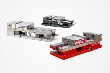
      • Fixed Jaw Vises
      • Self-Centering Vises
      • Adapter Plates
      • Mill Vise Jaws
      • Workholding Accessories
      • Vise Kits
      • Vise Parallels
      • Rotary Vise Kits
    • Manual Chucks
      Manual Chucks Shop All
      • 5C Indexer Chucks
      • 3-Jaw Chucks & Mounts for Mills
    • Milling
      Milling Shop All
      • Shell Mill Bodies
      • Milling Inserts
      • End Mills
      • Chamfer Mills & Inserts
      • Indexable End Mill Bodies
      • Ball End Mills
      • Chamfer End Mills
      • Roughing End Mills
      • Indexable Ball End Mills & Inserts
      • Shell Mill Kits
      • Chamfer Mill Kits
      • Indexable End Mill Kits
      • Dovetail Cutters
      • Indexable Dovetail Cutters
      • Engraving End Mills
      • Burrs
      • Keyseat Cutters
      • Corner Rounding End Mills
    • Lathe Tooling
      Lathe Tooling Shop All
      • Cut-Off Tooling
      • Cut-Off Tooling Kits
      • Turning Inserts
      • Grooving Tools
      • Small ID Grooving & Threading Tools
      • Threading Inserts
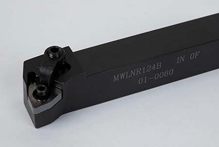
      • Threading Toolholders
      • Boring Bars
      • OD Toolholders
      • Cermet Turning Inserts
      • CBN Turning Inserts
      • Haas Notch Groove and Thread Inserts
      • Haas Notch Groove and Thread Toolholders
    • Lathe Toolholding
      Lathe Toolholding Shop All
      • TL & CL Toolholding
      • BOT Toolholding
      • BMT Toolholding
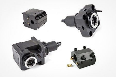
      • Live Toolholding
      • Reduction Sleeves
      • VDI Toolholding
    • Lathe Workholding
      Lathe Workholding Shop All
      • Live Centers
      • Spindle Liners
      • Quick-Change Collets
      • Lathe Collet Chucks
      • 5C Collets
      • 5C Collet Sets
      • Lathe Boring Rings
      • Lathe Jaws
    • ER Collets & Chucks
      ER Collets & Chucks Shop All
      • ER Collets
      • ER Sealed Collets
      • ER Tap Collets
      • ER Collet Sets & Accessories
      • ER Collet Chucks
      • Straight Shank ER Collet Chucks
      • Straight Shank Keyless Drill Chucks
    • Holemaking
      Holemaking Shop All
      • Carbide Drills
      • Indexable Drill Bodies
      • Indexable Drill Inserts
      • Modular Drill Bodies
      • Modular Drill Heads
      • Cobalt Drills & Sets
      • Center Drills
      • Reamers
      • Indexable Drilling Kits
      • Spot Drills
      • Spade Drill Bodies
      • Spade Drill Inserts
      • Countersinks
    • Threading
      Threading Shop All
      • Taps
      • Threading Inserts
      • Threading Toolholders
      • Thread Mills
      • Pipe Taps
      • Drill Tap Kits
    • Broaching
      Broaching Shop All
      • Broaching Toolholders
      • Broaching Inserts
    • Tool Management
      Tool Management Shop All
      • Tool Presetting Machines
      • Shrink Fit Machines
    • Tooling Accessories
      Tooling Accessories Shop All
      • Spindle Taper Cleaner
      • Haas Shop Lift
      • Toolholder Fixtures
      • CNC Clearing Fans
    • Deburring & Abrasives
      Deburring & Abrasives Shop All
      • Abrasive Pads
      • Deburr Tools
      • Deburr Wheels
    • Package Kits
      Package Kits Shop All
      • Chip Clearing Fan Kits
      • Cutting Tool Kits
      • Indexable End Mill Kits
      • Cut-Off Tooling Kits
      • Drill Tap Kits
      • Indexable Drilling Kits
      • Shell Mill Kits
      • Chamfer Mill Kits
      • Mill Toolholding Kits
      • Lathe Tooling Kits
      • Workholding Kits
      • Rotary Vise Kits
      • Vise Kits
      • 3-Jaw Chuck Kits for Mills
      • Reduction Sleeve Kits
    • Storage & Handling
      Storage & Handling Shop All
      • Tool Carts
    • Measuring & Inspection
      Measuring & Inspection Shop All
      • 7-Piece Measuring Kit
      • WIPS Stylus, 3-Pack
      • WIPS Replacement Stylus
      • Spindle Test Bar
      • Coolant Refractometer
      • Clamp Force Gauge
    • Apparel & Accessories
      Apparel & Accessories Shop All
      • Accessories
      • Apparel
    • HAAS TOOLING QUICK LINKS
      NEW PRODUCTS NEW PRODUCTS
      MOST POPULAR MOST POPULAR
      TOOLING PROMOS TOOLING PROMOS
      FINANCING & OPEN TERMS FINANCING & OPEN TERMS
      FAQs FAQs
      KITS CREATED FOR YOU KITS CREATED FOR YOU
  • Haas Service Parts Main Menu
      Automatic Pallet Changer Lathe Turret Tool Changer Chip Management Coolant Counterbalance Electrical Cabinet Enclosure Hydraulics Lubrication Maintenance Pendant Probing Rotary Spindle Tailstock
    • Haas Service Parts
    • Automatic Pallet Changer
      Automatic Pallet Changer Shop All
      • HMC - Automatic Pallet Changer
      • VMC - Automatic Pallet Changer
    • Lathe Turret
      Lathe Turret Shop All
      • Lathe - Turret
      • Live Tooling
    • Tool Changer
      Tool Changer Shop All
      • Side Mount
      • Umbrella
    • Chip Management
      Chip Management Shop All
      • Multi Auger
      • Single Auger
    • Coolant
      Coolant Shop All
      • Auxiliary Filter
      • HPC-300 (Lathe)
      • HPC-1000 (Lathe)
      • Oil Skimmer
      • Standard Coolant
      • TSC-300 (Mill)
      • TSC-1000 (Mill)
      • Coolant Refill
      • Loc-Line
    • Counterbalance
      Counterbalance Shop All
      • Charge & Discharge Hose
    • Electrical Cabinet
      Electrical Cabinet Shop All
      • Fans
      • Filters
      • Upgrade Kits
    • Enclosure
      Enclosure Shop All
      • Accessories
      • Air Nozzle
      • Decals
      • Door Bumpers
      • Lighting
      • Windows, Gaskets, & Weather Strip
      • Chip & Coolant Management
    • Hydraulics
      Hydraulics Shop All
      • Filters
      • Gauges
      • Heat Exchanger
      • Hoses
    • Lubrication
      Lubrication Shop All
      • Bijur Mechanical Lubrication
      • Minimum Lubrication
    • Maintenance
      Maintenance Shop All
      • Grease, Oil, & Sealants
    • Pendant
      Pendant Shop All
      • Floppy Disk & USB
      • Keypad
      • Keys
      • Lens
      • Gaskets & Seals
    • Probing
      Probing Shop All
      • Mill Probing
      • Lathe Tool Presetter
    • Rotary
      Rotary Shop All
      • Rotary Gaskets & Seals
    • Spindles
      Spindles Shop All
      • Couplings
      • Gaskets & Seals
      • Spindle Motor Drive
      • Gearbox Drive
      • Tool Release Piston
    • Tailstock
      Tailstock Shop All
      • Handles
  • Contact Us

×

Search Results

Web Pages

Images

    • <
    • 1
    • >
MyHaas Welcome,
!
Haas Tooling Guest Order History MyHaas/HaasConnect Sign In Register Haas Tooling My Account Order History Return History MyHaas/HaasConnect Sign Out Welcome, My Machines Latest Activity My Quotes My Account My Users Sign Out
Find Your Distributor
  1. Select Language
    1. English
    2. Deutsch
    3. Español - España
    4. Español - Méjico
    5. Français
    6. Italiano
    7. Português
    8. Český
    9. Dansk
    10. Nederlands
    11. Magyar
    12. Polski
    13. Svenska
    14. пост-советский
    15. Türkçe
    16. 中文
    17. Suomi
    18. Norsk
    19. الإنجليزية
    20. български
    21. Hrvatski
    22. Ελληνικά
    23. Română
    24. Slovenský
    25. Slovenščina
    26. 한국어
    27. 日本語
Search
×

Search Results

Web Pages

Images

    • <
    • 1
    • >

11 - HRP - Troubleshooting

Haas Robot Package - Operator's/Service Manual


  • 1 - HRP - Introduction
  • 2 - HRP - Legal Information
  • 3 - HRP - Safety
  • 4 - HRP-1 - Installation
  • 5 - HRP-2 - Installation
  • 6 - HRP-3 - Installation
  • 7 - HRP - Fence Installation
  • 8 - HRP - FANUC DCS Setup
  • 9 - HRP - Operation
  • 10 - HRP - Maintenance
  • 11 - HRP - Troubleshooting
  • 12 - Step by step Robot step videos

Go To :

  • 11.1 HRP - Troubleshooting

Introduction

This document will show you how to troubleshoot your Haas Robot Package.  If you do not find the alarm or symptom on this document please perform the following and contact the service department.

  • Machine Serial Number.
  • Robot Serial Number and F Number.
  • Error Report at time of alarm or issue. If possible, the robot needs to be connected to the machine.
  • If running Robot scheduler jobs, need all the machine programs and robot jobs. Error report only saves the current programs.
  • MD Backup. See MD Backup Section below for instructions.
  • Photos or video of issue.

Robot and Haas Communication Alarms

These alarms and symptoms can happen when the machine and the robot are not communicating.

Alarm / Symptom Possible Cause Corrective Action
9147 Robot Protocol Version Mismatch Connecting to a robot that has been power cycled may cause a Version Mismatch. This causes all robot functions to be locked until the alarm is cleared. Release the E-Stop and press RESET to clear the alarm. Then press the E-Stop and press F1 to connect the robot
9155 ROBOT EXCEEDED MAX PAYLOAD Robot attempted to clamp a part which would result in exceeding the max payload allowed. Reduce part weight. See layout drawings for the payload specifications for each robot size.
9156 ROBOT COMMAND FAILED, No subcode or other robot alarms. Robot software was downgraded after a Robot Software Update. Example: Original Robot Software version 1.22 and downdgraded to version 1.15. See HRP - Initialized Start section below.
9160 ROBOT EMERGENCY STOP The Robot Emergency Stop button was pressed either from the robot control box or the remote pendant. Or robot estop chain is broken. Please release the Robot Emergency Stop button(s) and press reset to proceed. Verify all robot estops are released. Verify estop wiring (including external estop inputs) to robot are intact and correctly wired.
Robot motion stops and System Message & Notification 20021. 32 Robot SYST-032 ENBL signal from UOP is lost. The FANUC control disconnected from Haas Control. See the HRP Disconnect Alarms section below to increase the Modbus TCP Timeout & Disable DHCP.
Robot motion stops and System Message & Notification 20021. 34 Robot SYST-034 HOLD signal from SOP/UOP is lost. The FANUC control disconnected from Haas Control. See the HRP Disconnect Alarms section below to increase the Modbus TCP Timeout & Disable DHCP.
Robot motion stops and System Message & Notification 20021.224 Robot HOST-224 DHCP: No response from server. The FANUC control disconnected from Haas Control. See the HRP Disconnect Alarms section below to increase the Modbus TCP Timeout & Disable DHCP.
The Robot won't Connect to the CNC The wiring from the interface to the Haas Control is not correct. Make sure you have connected the terminal connectors on TB-1B in the correct order.  Refer to the Robot Installation Procedure, Electrical section.
The robot is not unlocked and activated.

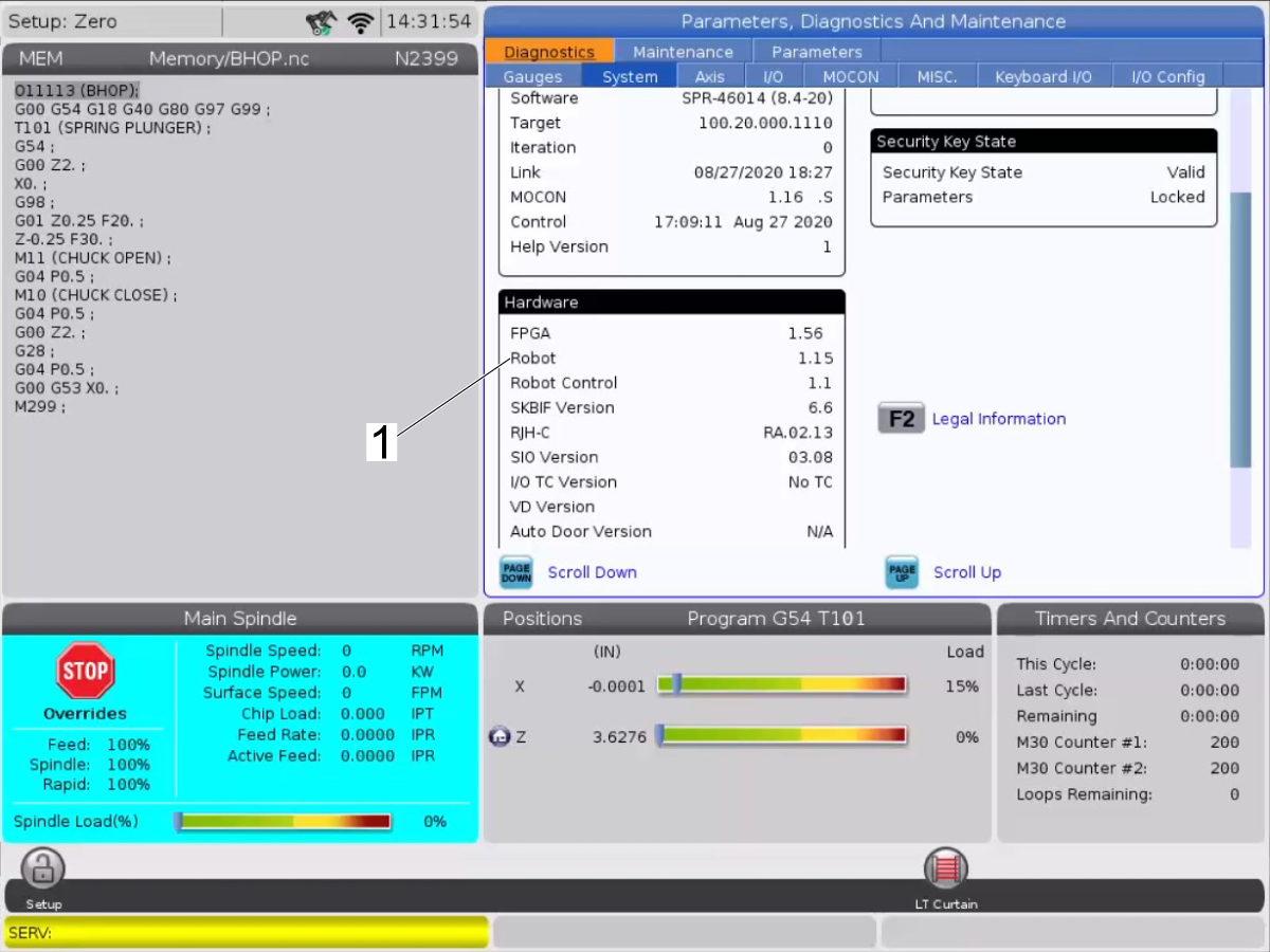
The first time connecting a robot to a machine, a Robot Activation window will pop-up. This pop-up shows the Software Version of the machine, the MAC address of the robot, and the Machine Generated Code used for Machine Time Extension on the portal.

Note: Go to the Robot MAC Address section to find the MAC address using a laptop.

The CNC software is outdated. Make sure the software is 100.20.000.1200 or higher.  Refer to the Robot Installation Procedure machine requirements section.
The Robot IP address and the CNC are mismatched. If the Robot Software is 1.11 or lower. Upgrade the Robot control to 1.15 or higher. Contact your HFO for more information. See Robot IP Address section for more info.
The arm moved during power off. Connect & Calibrate Haas Robot using the video below.
The RJ45 to USB adapter is defective.
  • Make sure the USB cable is connected to the correct USB port on the main processor. 
  • Make sure that the user USB port works by plugging a USB device and determine if the USB device gets detected,  if it does not get detected follow the USB Troubleshooting Guide and troubleshoot the USB Ports. 
  • If all the above check out correct, then unplug the RJ45 from the adaptor and connect it to the RJ45 on a laptop and make sure you are able to connect to the robot via the IPedant.  If you are able to connect to the robot via the laptop then the RJ-45 to USB adapter is defective.
Robot does not jog in a straight line, It makes an arcing motion when moving in Cartesian along a single axis. The robot joints were not lined up to the correct location when the Mastering or Quick Mastering procedure was set. Move all joints to zero and check to see if the lines on both sides of the joint are lined up. Line the marking up on all axis and redo the Master/Quick Master procedure. 

The following errors appear when trying to connect to the iPendant from a PC:

  • "Disconnected From Controller"
  • "iPendant has never been connected"
The robot may need to be reinitialized.
Do the following steps:
 
  1. Make a backup by following this procedure: How to Make an Image Backup
  2. Reinitialize the robot by following this procedure: How to Reinitialize Robot
E-Stop alarm wont clear. Jumper might be missing from JP1 on the SIO PCB.

Verify the jumper is installed on the SIO PCB at JP1. If it is not installed, reinstall it.

Machine needs to be Manually Recovered or goes into Robot APL Recovery. The Robot cycle was interrupted or the machine/robot was in a unsafe condition and needs to be recovered. See the Haas Robot - APL Recovery section in HRP Operation for more information.
Machine goes into Robot APL Recovery between two scheduled jobs. Machine motion was active when next job was started. Add a machine dwell to the Post Run sequence in the first job. The dwell needs to be long enough to give the robot enough time to finish dropping off the part and moving to ready position. Start at around 15-20 seconds and adjusting up or down from there. The dwell is long enough if the second job is able to start and the machine does not go into Robot APL Recovery.

Robot Command Failed Alarms

These alarms are generated when the robot fails to execute a command. A sub-alarm number indicates faults ID and is provided by FANUC robot.

Alarm / Symptom Possible Cause Corrective Action
  • 9156.004 SRVO-004 Fence Open
  • 9156.037 SRVO-037 IMSTP input (Group:1)
  • 9156.406 SRVO-406 DCS SSO SVOFF input 1,1
The TB1-B and TB3B Connectors are plugged into the wrong location or unplugged. Plug the connectors into the correct location. See the SRVO-004 Fence Open section below.
9156.050 Robot Command Failure SRVO-050 Collision Detect Alarm Jogging the robot in setup mode and the center of rotation of J6 is in line with the center of rotation of J4. Then rotating W or P, will cause J4 axis to attempt to rotate at a very fast speed. This singularity point is called the wrist singularity. Press RESET to clear the alarm. Do not jog the robot through this singularity point.
The robot motion file does not have enough points producing a non-smooth motion. Add more points to the motion file smoothing out the robot motion.
9156.406 SRVO-406 DCS SSO SVOFF input 1,1 The K9 and K10 Relays on I/O PCB are not installed. Make sure you have the K9 and K10 relays installed on the I/O PCB.  Refer to the Robot Installation Procedure, Electrical section.
9156.406 SRVO-406 DCS SSO SVOFF input 1,1 The fence is open in Run Mode. Make sure the interlock is working and that machine is receiving the interlock input signal.
The TB3-B wiring is damaged or miswired. Check the wiring for the TB3-B connector. Compare the wiring of the connector to the wiring diagram.
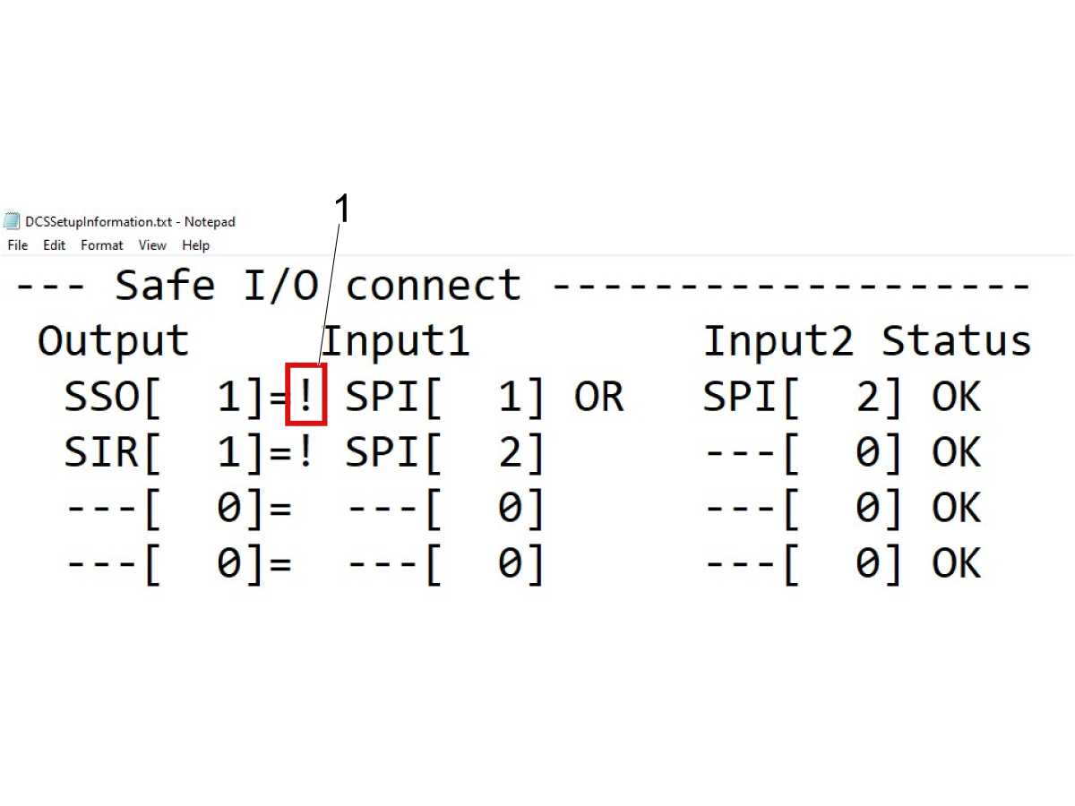
The DCS Cartesian Position Check Zone was not setup. Follow the DCS Cartesian Position Check Zone procedure.
9156.037 SRVO-037 IMSTP input (Group:1) The TB3-B wiring is damaged or miswired. Check the wiring for the TB-3B connector. Compare the wiring of the connector to the wiring diagram.
9156.062 ROBOT COMMAND FAILED SRVO-062 BZAL alarm The batteries in the robot arm have died. Follow the HRP - Battery Replacement procedure to replace the batteries and follow the HRP - Quick Mastering procedure to remaster the robot.
9156.115 SRVO-115 Limit Error (Motion Group Number, Axis Number) The linear path passes outside of the axis limit. Re-Teach program points or use a Joint position to record the axis in a position that is in the middle of its travel limits.

9156.378 FANUC ROBOT ALARM - SFDI12 Status abnormal

or

9156.378 FANUC ROBOT ALARM - SFDI22 Status abnormal

The K9 and K10 Relays on I/O PCB are not installed. Make sure you have the K9 and K10 relays installed on the I/O PCB.  Refer to the Robot Installation Procedure, Electrical section.
9156.219 SRVO-219 Safety I/O brd fuse%d blown %s Failed to successfully execute a robot command. A fuse on the additional Safe I/O board has blown. The TB1-B or TB3-B wiring is damaged, miswired, or plugged into the wrong location. The number of the safe I/O device that the alarm occurs is displayed in the end the message such as (1). The safe I/O device number is displayed in DCS Safe I/O device menu. Correct the wiring issue. Replace the fuse on the additional Safe I/O board or the additional Safe I/O board. See the Fuse Replacement Section below.
9156.266 SRVO-266 FENCE1 status abnormal Damaged or miswired TBOP20 wires or connector. Check that the signal cables for the fence is not damaged or miswired. TBOP20 connector and cables in the Fanuc Control Box or the Interface Box M12 connector Robot Signals. See SRVO-266/267 FENCE1/2 status abnormal section below.
9156.267 SRVO-267 FENCE2 status abnormal Damaged or miswired TBOP20 wires or connector. Check that the signal cables for the fence is not damaged or miswired. TBOP20 connector and cables in the Fanuc Control Box or the Interface Box M12 connector Robot Signals. See SRVO-266/267 FENCE1/2 status abnormal section below.
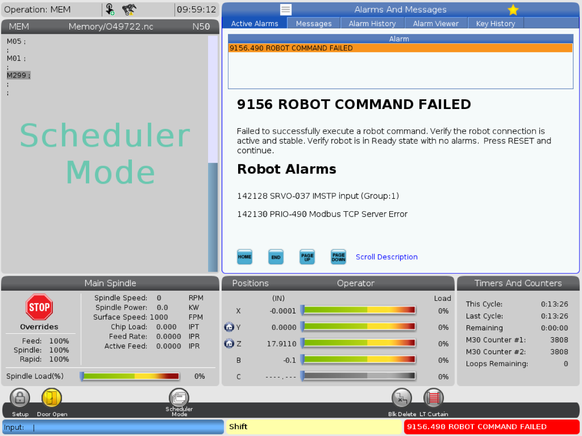
9156.490 PRIO-490 Modbus TCP Server Error Interference or faulty RJ-45 Ethernet cable.

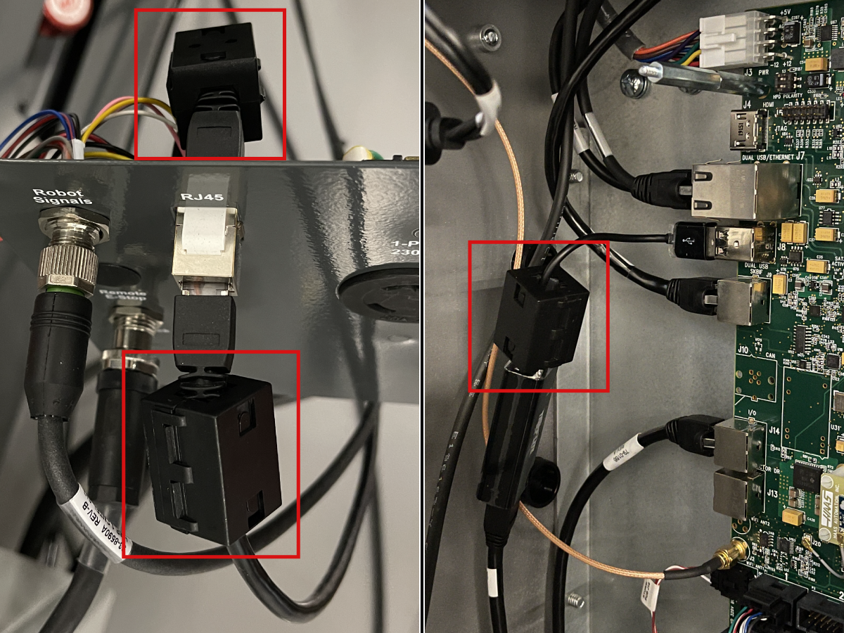
Depending on the Robot build date the cables were not built with ferrite filters installed. Install ferrite filters PN: 64-1252 to both RJ-45 Communication cables at the electrical interface box and to the USB to Ethernet Adapter at the Main Processor PCB. See the Ferrrite Filter section below. If the alarm continues, test the cables refer to Network Cable Tester Tool procedure.

If the cable passes the network cable test, see the HRP Discconect Alarms section below to increase the Modbus TCP Timeout & Disable DHCP.

Fanuc Robot Alarms

These alarms are generated when the robot is at fault state.  A sub-alarm number indicates faults ID and is provided by FANUC robot.

Alarm / Symptom Possible Cause Corrective Action
9150.219 SRVO-219 Safety I/O brd fuse%d blown %s Failed to successfully execute a robot command. A fuse on the additional Safe I/O board has blown. The TB1-B TB3-B wiring is damaged, miswired, or plugged into the wrong location. The number of the safe I/O device that the alarm occurs is displayed in the end the message such as (1). The safe I/O device number is displayed in DCS Safe I/O device menu. Correct the wiring issue. Replace the fuse on the additional Safe I/O board or the additional Safe I/O board. See the Fuse Replacement Section below.
9150.378 FANUC ROBOT ALARM - SFDI12 Status abnormal

or 

9150.378 FANUC ROBOT ALARM - SFDI22 Status abnormal
The K9 and K10 Relays on I/O PCB are not installed. Make sure you have the K9 and K10 relays installed on the I/O PCB.  Refer to the Robot Installation Procedure, Electrical section.
9150.402 FANUC ROBOT ALARM - SRVO-402 DCS Cart. position limit This alarm is generated when the robot has a DCS Cartesian Position Check Zone setup with a speed limit and the robot is jogged outside the work zone above the speed limit. Lower the feed rate and jog back into the DCS Cartesian Position Check Zone. Verify the work zone is setup correctly by checking the 4D DCS Display.
9150.403 SRVO-403 DCS Cart. speed limit, 9150.404 SRVO-404 DCS Joint pos. limit, or 9150.405 SRVO-405 DCS Joint speed limit The DCS Zone was not setup correctly. Cartesian Speed Check, Joint Position Check, or Joint Speed Check is Enabled when it should be Disabled. See Disable DCS Speed Check section below for steps to disable.
9150.488 FANUC ROBOT ALARM - SRVO-488 DCS CPC Speed Limit This alarm is generated when the robot has a DCS Cartesian Position Check Zone setup with a speed limit and the robot is jogged outside the work zone above the speed limit. Lower the feed rate and jog back into the DCS Cartesian Position Check Zone. Verify the work zone is setup correctly by checking the 4D DCS Display.
9152.x Robot Hit Joint Limit or robot does not jog Jogging the robot in setup mode and the center of rotation of J6 is in line with the center of rotation of J4. Then rotating W or P, will cause J4 axis to attempt to rotate at a very fast speed, traveling past the travel limit. This singularity point is called the wrist singularity. The Joint Position will be greater than the Robot Joint Travel Limit. The Sub-Code of the alarm represents the joint number. Connect to the robot using the Remote Pendant through the web interface. Clear the alarm and jog the robot joint away from the travel limit. Reconnect to the Haas control.

Haas Robot - Active Alarms

More than one Fanuc alarm may be present if the machine generates an alarm. Navigate to the Active Alarms tab to view all active Fanuc alarms.


Connect & Jog Haas Robot

If alarm 9152.x Robot Hit Joint Limit is generated follow the video below. Connect to the robot using the Remote Pendant through the web interface. Clear the alarm and jog the robot joint away from the travel limit. Reconnect to the Haas control.

Connect & Calibrate Haas Robot

HRP Disconnect Alarms - Modbus TCP Timeout & Disable DHCP

If robot motion stops and System Message & Notifications 20021. 32 Robot SYST-032 ENBL signal from UOP is lost, 20021. 34 Robot SYST-034 HOLD signal from SOP/UOP is lost, or 20021.224 Robot HOST-224 DHCP: No response from server is generated in the Alarm History follow the video below. Connect to the robot using the Remote iPendant through the web interface. Verify if ferrite filters are installed on the robot signal cables and install if missing. See Ferrite Filter Installation section below for more information.

Ferrite Filter Installation

Depending on the Robot build date the cables were not built with ferrite filters installed. Install ferrite filters PN: 64-1252 to both RJ-45 Communication cables at the electrical interface box and to the USB to Ethernet Adapter at the Main Processor PCB. 

HRP-1 Safety I/O PCB Fuse 1 Replacement

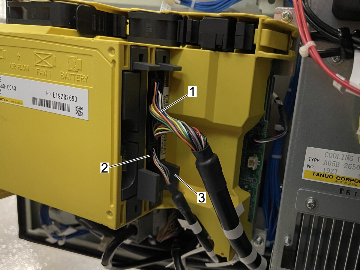
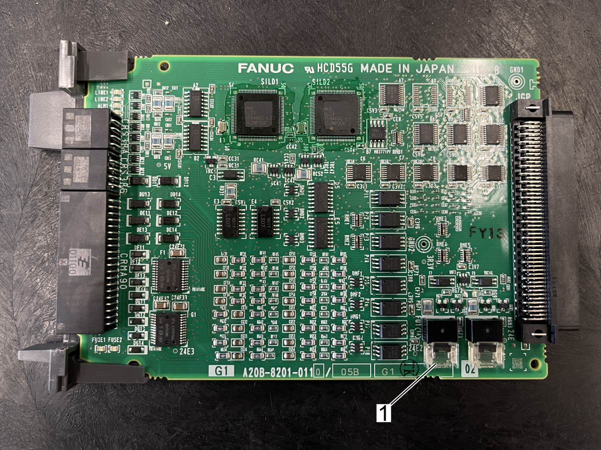
If Alarm SRVO-219 Safety I/O brd fuse1 blown (2) is generated. The TB1-B or TB3-B wiring is damaged, miswired, or plugged into the wrong location. Correct the wiring issue. Then perform the following steps to replace Fuse 1 on the Safety I/O Board. Fuse 1 A60L-0001-0290/LM10C is found in 93-3378.

1

Power down the machine and robot to access the Fanuc Control box. Open the Control door. Disconnect cables [1] & [2].

Press the tab[3] to release and remove the Safety I/O PCB.

2

Replace Fuse 1[1] on the Safety I/O PCB.

SRVO-266/267 FENCE1/2 status abnormal

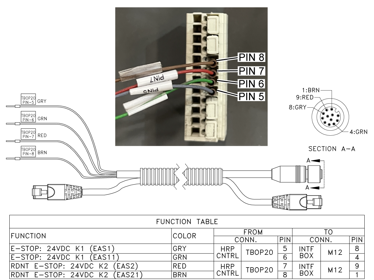
The Fence inputs to the Fanuc Control start at the Safety Relay in the Electrical Interface box and plug into TBOP20 in the Fanuc Control box. Inspect the cables for damage.

Example: The pin on the Robot Signal cable M12 connector was pulled out[1].

Inspect the TBOP20 connector and pins. Inspect the M12 connector that plugs into the Electrical Interface box.

EAS1 & EAS11 are SRVO-266 Fence 1.

EAS2 & EAS 21 are SRVO-267 Fence 2.

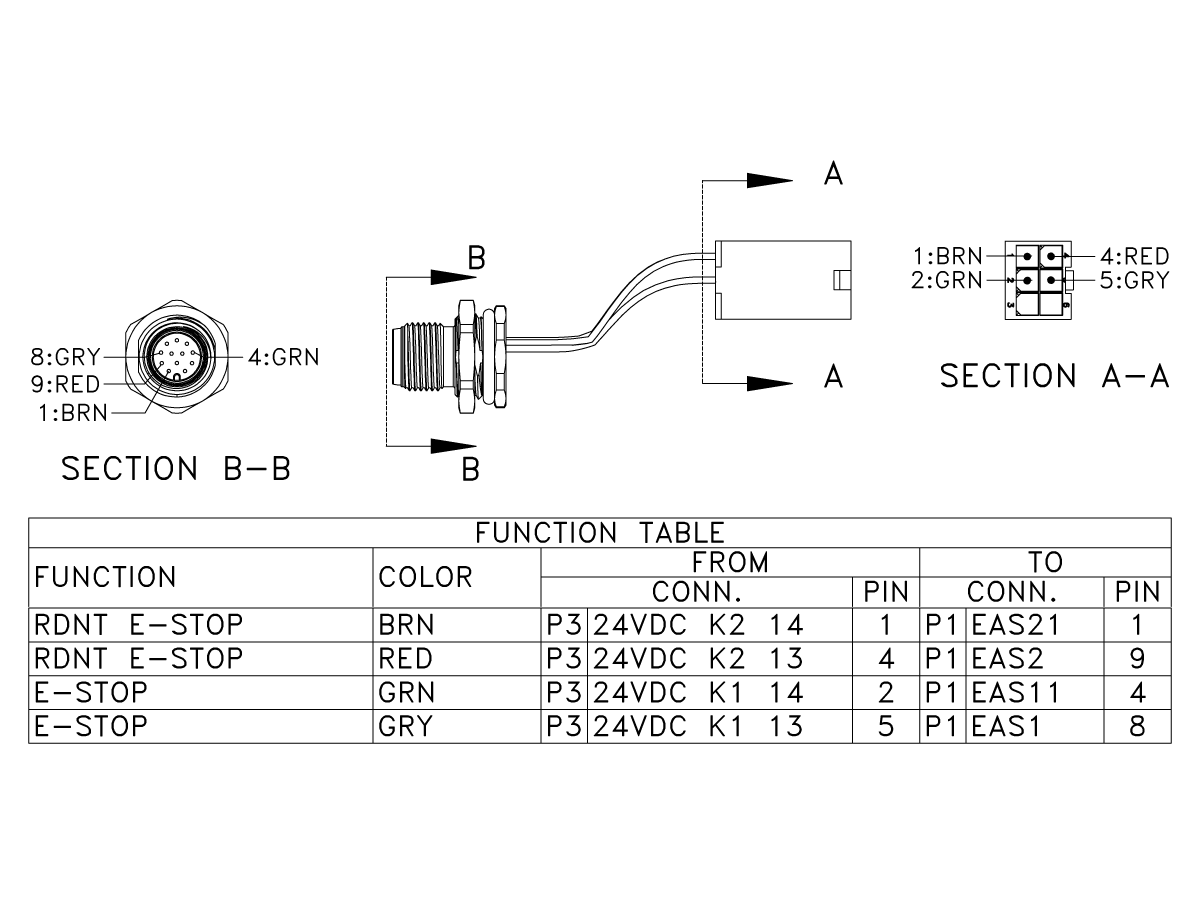
Inspect the M12 connector on the Electrical Interface box. Inspect the cables that plug into the Safety Relay.

EAS1 & EAS11 are SRVO-266 Fence 1.

EAS2 & EAS 21 are SRVO-267 Fence 2.

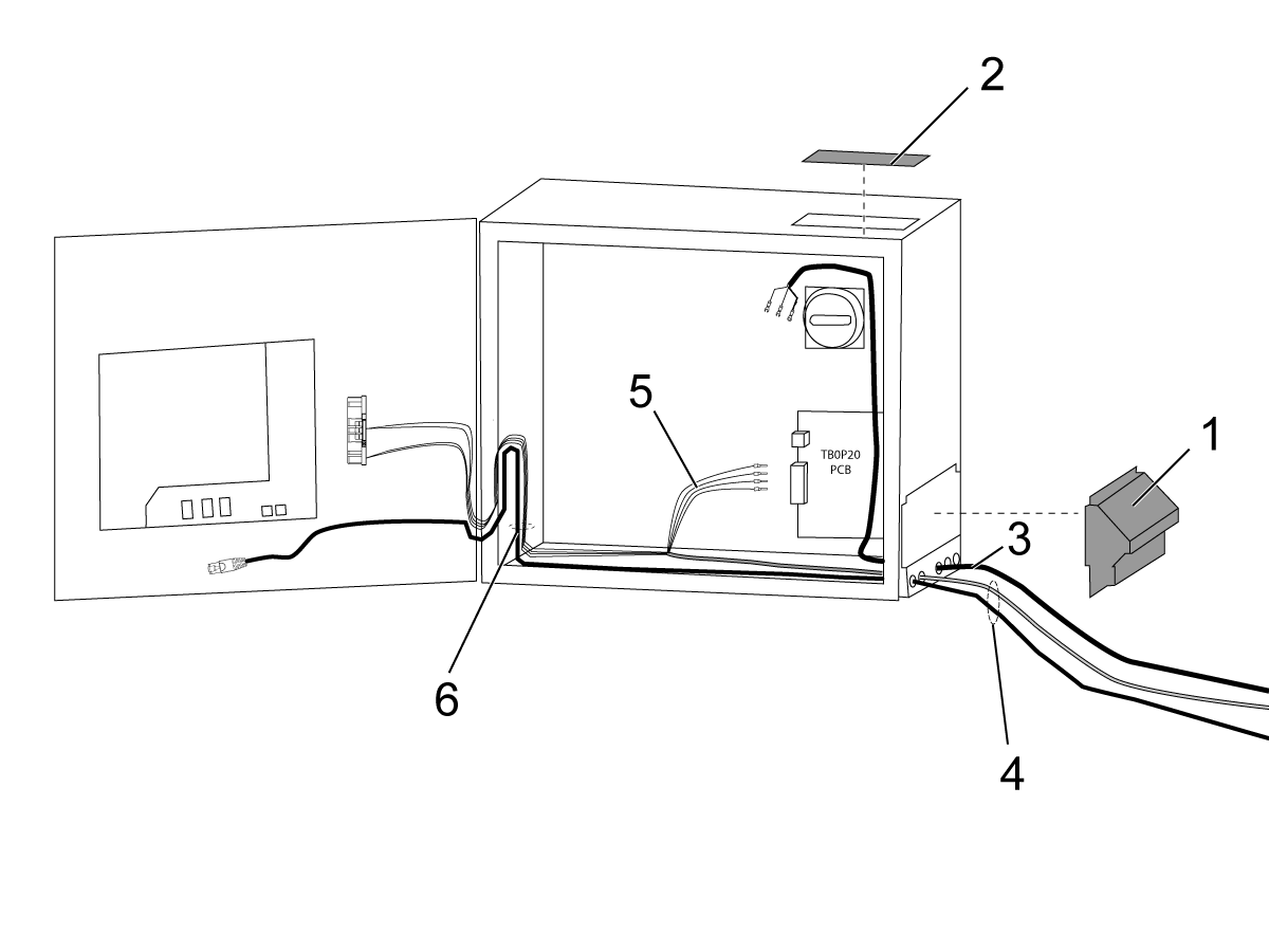
Robot Control Wiring HRP-1

1

Robot Control Box
  • Open the Robot Controller door by using a straight head screwdriver to turn the latch counter-clockwise,  then turn the breaker counter-clockwise past its off position.
  • Remove the cable cover [1] from the robot control box
  • Remove the top cover [2].  This will make the installation of the power cable easier.
  • Feed the 230VAC Power cable P/N 33-5830 [3] as shown. 
  • Feed the Robot Control Signal cables P/N 33-8590 [4] as shown.
      Note:
    Make sure the Robot Control signal cables P/N 33-8590 are as far away from the power cable as possible. 

  • Pull enough slack on the cable with ferrules [5] to reach the TB0P20 PCB,  you will add connector to these wires in step 7.
  • Route the RJ45 cable and the cable with the large connector from cable P/N 33-8590 together [6] as shown.

2

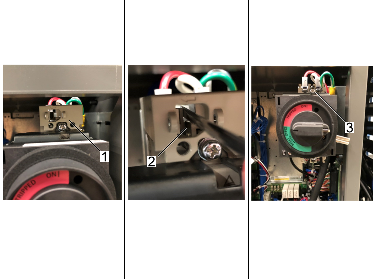
To connect the power cable, remove the plastic cover from above the Breaker.  To remove cover, insert a straight-head screwdriver into the opening, and push the tab to the left allowing the cover to slide forward.

Connect the cables to L to 1 and N to 3.  Connect the ground to the plate to the right of the Breaker.

After the power cable is connected, reinsert the plastic cover.

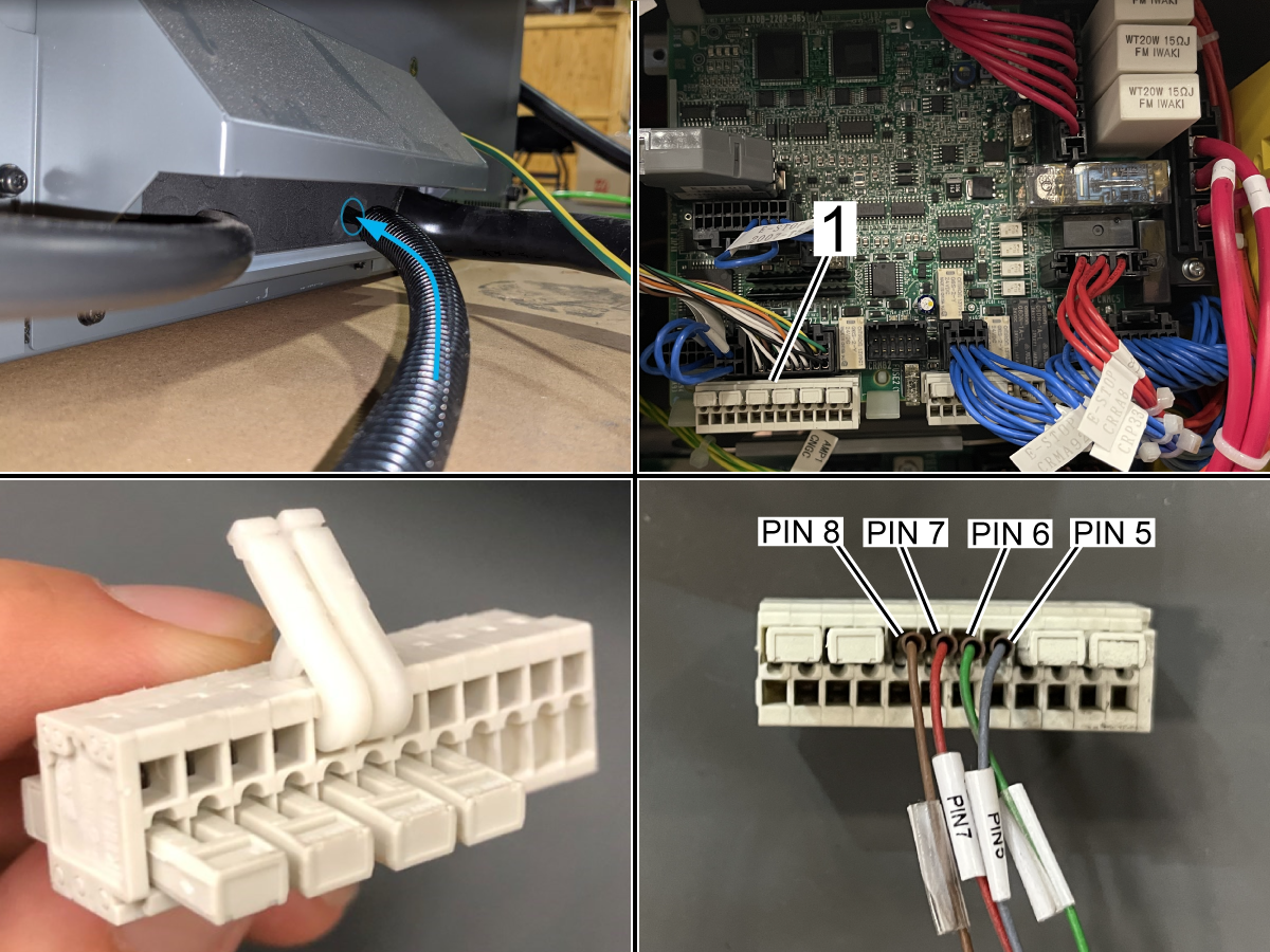
Robot Control Wiring HRP-2/3

1

If cable 33-8591A or 33-8592A is not installed to the Fanuc Control box, perform the following steps:

Route the cable through the back of the Fanuc Control box.

Remove the connector at TBOP13[1] inside the Fanuc Control box.

Remove the jumpers and install the wires in the connector in the following order with the tool included in the Fanuc Install kit.

Note: Both tools need to be used to install the ferrules.

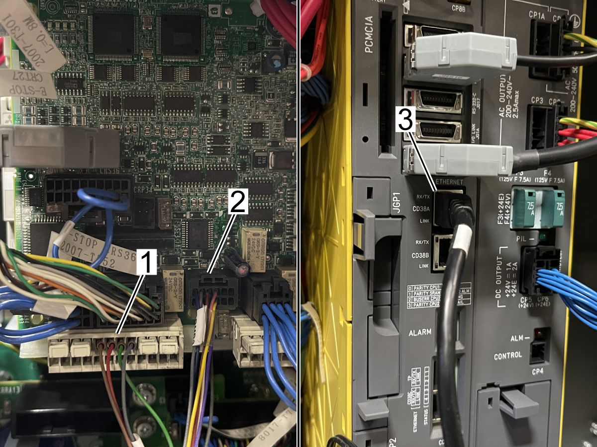
2

Install the cable labled TBOP20 to connector TBOP13[1].

Install the cable labled CRMB2 to the connector labled CRMB2[2].

Install the RJ-45 Ethernet cable labled ENET CD38A to the Ethernet Port 1 labled CD38A[3].

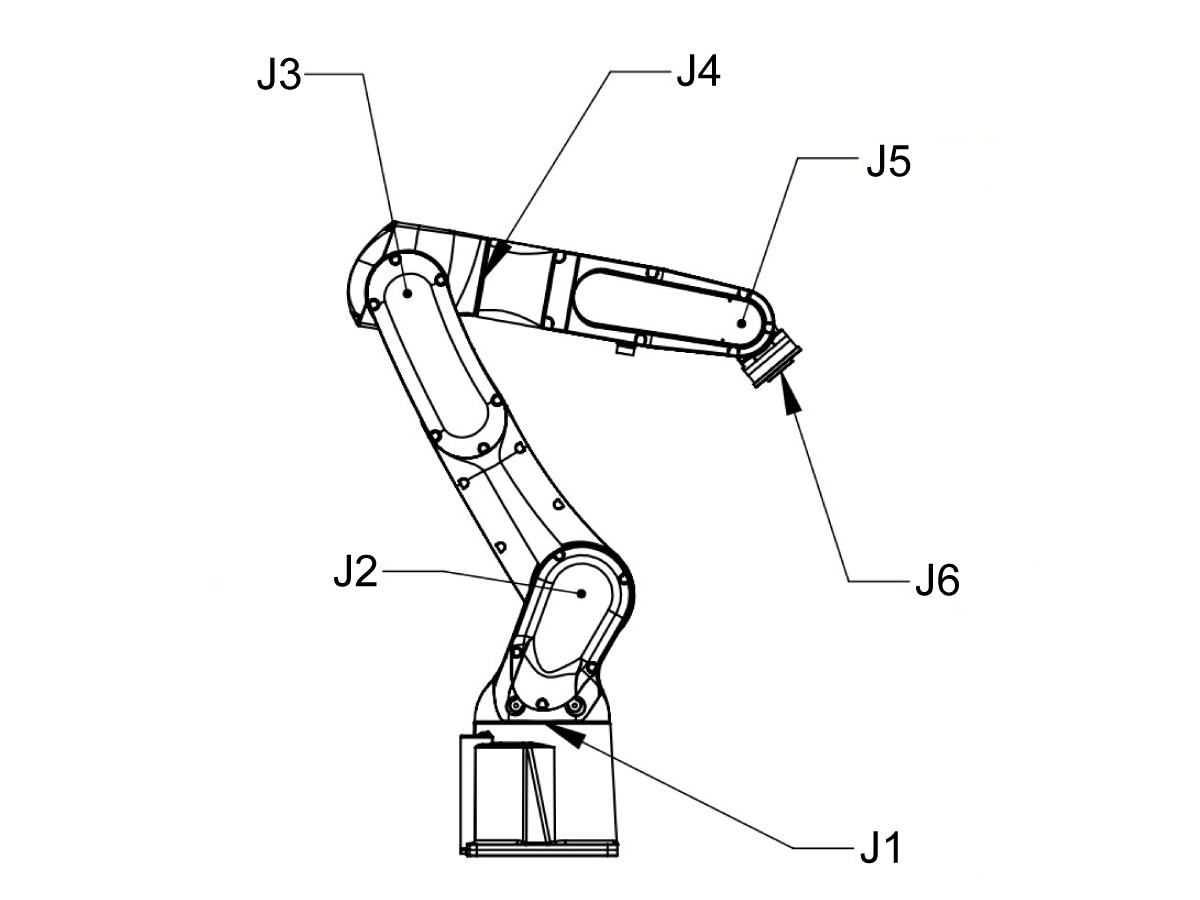
HRP-1 Joint Travel Limits

Robot Joint Travel Limits

J1 (+/-170°)

J2 (+/-122.5°)

J3 (+/-215°)

J4 (+/-190°)

J5 (+/-125°)

J6 (+/-360°)


Robot IP Address

Depending on the Robot build date. The IP address of the robot control may be different then the IP address in the Haas control. If the Robot Software is 1.11 or lower. Update the Robot Software to 1.15 or higher and verify the following parameters values are set correctly:

2262 Robot IP Address to 10.72.65.82
2263 Aux IP Address to 10.72.65.77

Recheck the connection.

Disable DCS Cartesian Speed Limit

If Alarm 9150.403 SRVO-403 DCS Cart. speed limit, 9150.404 SRVO-404 DCS Joint pos. limit, or 9150.405 SRVO-405 DCS Joint speed limit is generated. The DCS Zone was not setup correctly. Cartesian Speed Check, Joint Position Check, or Joint Speed Check is Enabled when it should be Disabled. Follow the steps below to disable these settings.

1

Login to the HMI Jogging Pendant from your web browser.

Navigate to the User Frame Setup view.

Navigate to DCS Menu.

Enable the pendant by hitting the ON/OFF button on the top right.

2

Depending on the alarm generated go into the enabled setting. SRVO-404 is Joint Position Check (3), SRVO-405 is Joint Speed Check (4), and SRVO-403 is Cart. Speed Check (6).

Go into No. 1.

Disable the position check No. 1 by selecting then pressing [CHOICE] at the bottom.

Press PREV 3 times to get back to the Main DCS screen.

3

Now we will apply the all the changes we made in the DCS menu. Any DCS section that was changed since last APPLY will show a RED CHGD next to it. Press APPLY at the bottom.

Enter 1111 for the Master Code.

This will take you to another menu that will show you the changes made in the DCS menu since last apply. Press OK if all changes are correct.

Close the HMI Pendant Window.

Cycle power on the robot controller by turning the power switch OFF, waiting 5 seconds then back ON.

HRP-1 Teach Pendant Plug Location

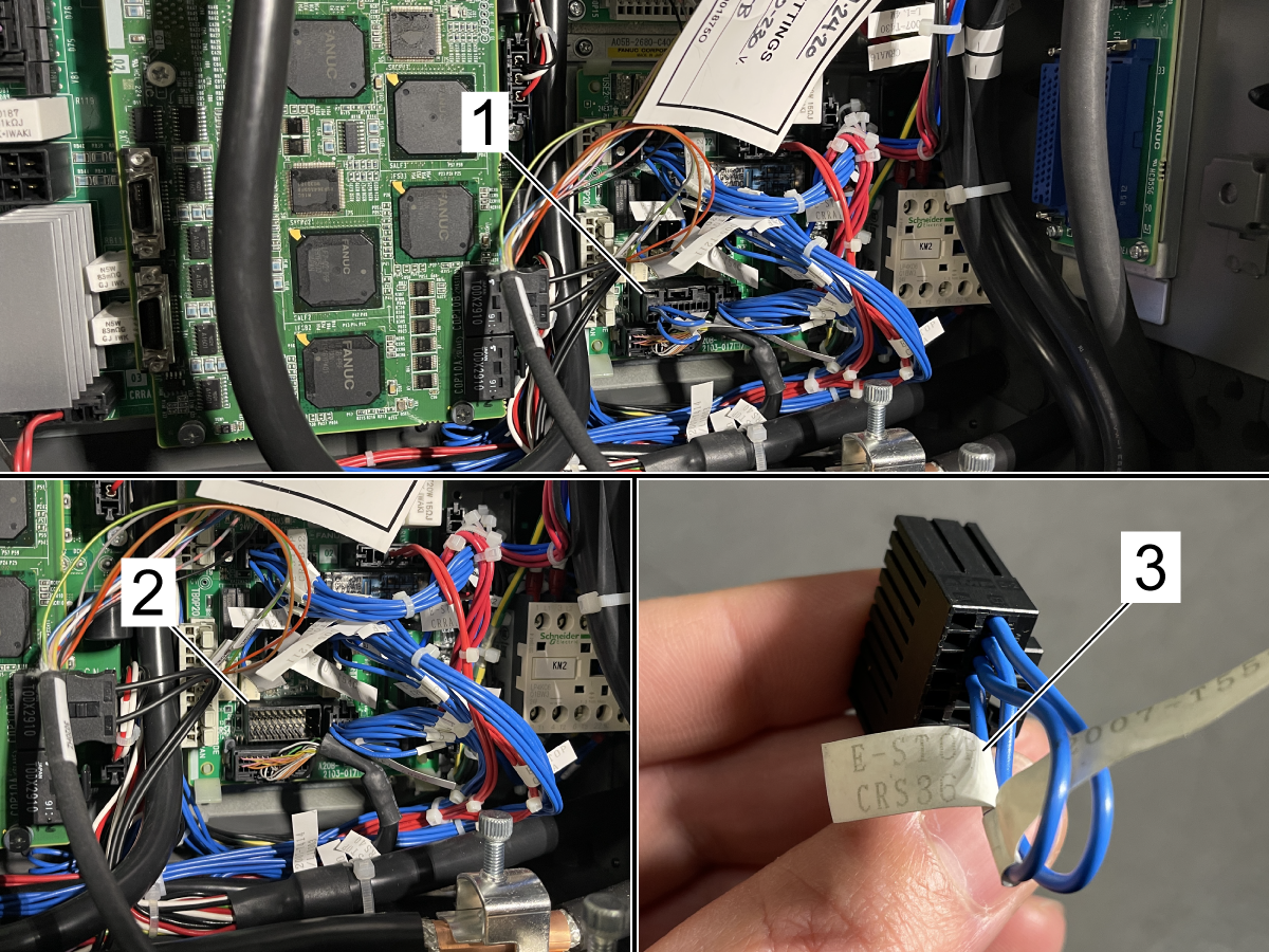
Remove the Teach Pendant Jumper[1] labled E-STOP CRS36 [3] from the E-STOP Board.

Plug the Fanuc Teach Pendant Cable in to this location[2].

Note: When finished using the Fanuc Teach Pendant, replace the Jumper on the E-STOP Board.

HRP-1 RJ45 Plug Location for iPendant

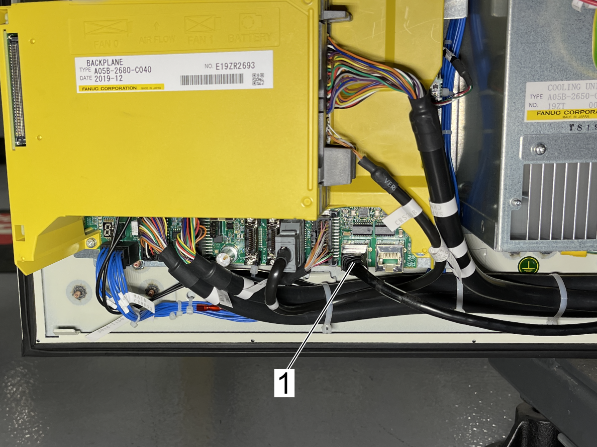
Remove the RJ45 cable[1] labled CD38B from Port 1 on the Fanuc Control Box door.

Plug in the RJ45 cable connected to the laptop to the plug location CD38A.

Note: When finished using the Fanuc iPendant, plug in the cable labled CD38B.

HRP - Initialized Start

If Alarm 9156 ROBOT COMMAND FAILED with no subcodes or other robot alarms. Perform the following steps.

Note: A Fanuc Teach Pendant is required to perform an Initialized Start.

1. Take a MD Backup of the current condition. See Fanuc Memory Device (MD) Backup section below.

Warning: If a MD Backup is not taken before precedeing, the robot will need to be recovered.

2. Power off the robot by rotating the Robot Circuit Breaker.

3. Press and hold the F1 and F5 keys

4. Turn on the Robot Circuit Breaker while holding the F1 and F5 keys until the Boot Menu is displayed.

5. On the boot menu select INIT START.

6. Restore ROBOT_ACTIVATION and SYSMAST.SV files. Follow the Instructions linked below.

Restore ROBOT_ACTIVATION and SYSMAST.SV Files

Fanuc Memory Device (MD) Backup

Fanuc Memory Device (MD) Backup - No Audio

To create a Memory Device (MD) backup of the robot. Connect to the Fanuc Control with a laptop and iPendant. See Connect & Jog Robot video above.

Insert the thumb drive with the MD backup into the USB port in the black door on the controller (UD1:) or USB port on the teach pendant (UT1:).

Navigate to the Navigate pendant.

Set the default device to the device you want. The two options are UT1: for the Fanuc Teach Pendant or UD1: for the USB port on the front of the Fanuc Control Box.

  • Press MENU and then File.
  • Press F1, [TYPE]. Select File.
  • Press F5, [UTIL]. Select Set Device.
  • Navigate to the Device you want to save the backup to, UT1: or UD1:.
  • Press F4, [BACKUP]. If you do not see [BACKUP], press [FCTN] and select RESTORE/BACKUP.
  • Select All of Above and press [ENTER].
  • It will prompt you select the backup operation you want to perform. Press F4, [YES] to back up the current file.
  • The backup process will take a few minutes to complete.

Fanuc iPendant RJ45 to USB Ethernet Adapter Settings

Fanuc iPendant RJ45 to USB Ethernet Adapter Settings - No Audio

If the laptop used to connect to the Fanuc control does not have a RJ45 Ethernet port. Use a RJ45 to USB adapter PN: 33-0636 to connect to the laptop. Follow the video to change the adapter settings and confirm connection.

Restore Fanuc Memory Device (MD) Backup

1

 Note: A Fanuc Teach Pendant is required to restore a MD Backup.

 Warning: If a MD Backup is not taken before precedeing, the robot will need to be recovered.

Insert the thumb drive with the MD backup into the USB port in the black door on the controller (UD1:) or USB port on the teach pendant (UT1:).

Perform a Controlled Start:

  • Cycle power to the Fanuc controller.
  • Before the robot starts to power back up, hold PREV and NEXT on the teach pendant to be taken to the Configuration Menu when the controller is booting up.
  • Type 3 and press ENTER to initiate a Controlled Start.

Once the teach pendant boots back up:

  • Press the MENU button then select File and press ENTER.
  • On the FILE menu, press F5 [UTIL]. If [UTIL] is not shown above F5, press NEXT until [UTIL] is shown and then press F5.
  • Select Set Device.
  • Select USB Disk (UD1:) or (UT1:) depending on USB port.

2

Navigate to the directory in which your MD backup is stored. If there is a folder within a folder. Navigate until there is a list of files that contain the back up.

  • If [RESTOR] is not shown above F4, press FCTN, then select RESTORE/BACKUP to toggle between restore and backup.
  • Press F4 [RESTOR].
  • Select the type of restore action that you want: All of above.

You will be prompted with “Restore from Ud1: (OVERWRT)?”.

  • Press F4 YES.

The TP will show “Accessing device. PREV to exit.” for about 30-60 seconds, then the restore will commence. Once it begins, typical restore time is ~2-6 minutes, depending on the contents of your robot.

As many files as possible will be restored. Once the restore is complete, you will need to perform a Cold Start:

  • Press FCTN
  • Select START (COLD)

Reset the DCS Zone.

SRVO-004 Fence Open

Plug the connectors into the correct location according the Electrical Diagram.

TB1-B[1] is the connector on the right.

TB3-B[2] is the connector on the right.

Robot MAC Address

1

Follow this video to connect a laptop to the robot.

2

Once connected to the robot on the laptop, select Current Robot Status [1] from the menu on the left. 

Then click Summary Configuration/Status [2].

3

At this point the F number [1], if needed, can be found on this page.

Click the Ethernet Config Info link [2] and the MAC address can be found on this page at [3].

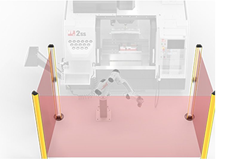
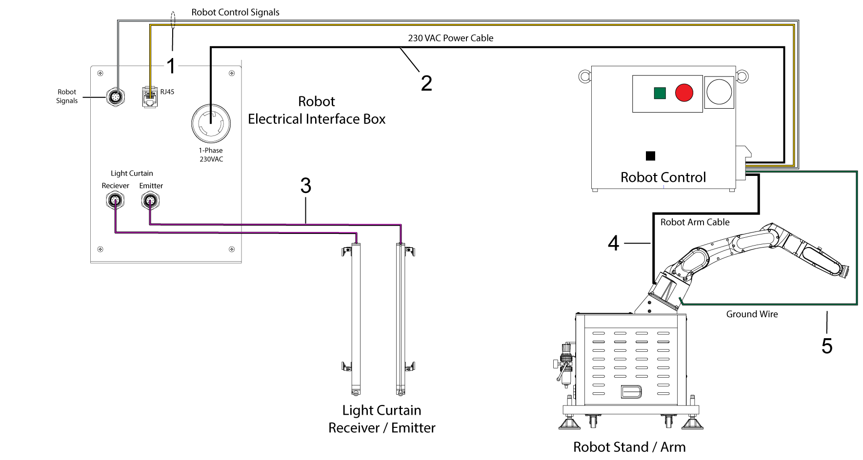
Robot With Light Curtain

Robot Electrical Box to Robot Control
  • Connect the E-STOP cable [1] P/N 33-8550 from Robot Electrical Interface Box  to the Robot External E-stop Box (see diagram).
  • Connect the Robot Control Signal Cables [2] P/N 33-8590A to the Robot Electrical Interface Box.

Robot Power

  • Connect the 230VAC Power Cable [3] P/N 33-8530 to the Robot Electrical Interface Box.

Light Curtain

  • Connect the Light Curtain cables [4] to the Receiver/ Emitter connections at the Robot Electrical Interface box.
Robot Arm
  • Connect the Robot Control Cable [5] to the Robot Arm.

Ground Wire

  • Connect the Ground Wire [6] from the Chassis of the Robot Control to the Robot mount.

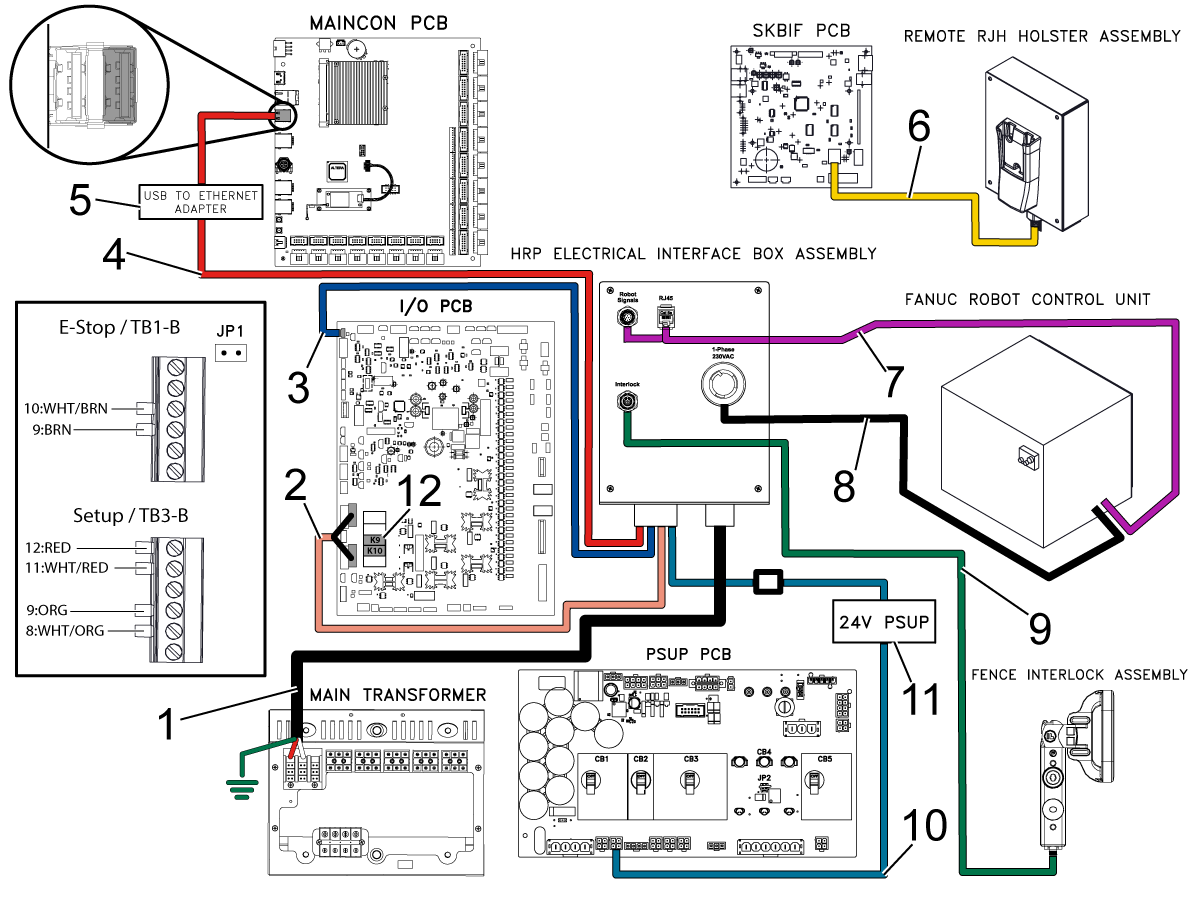
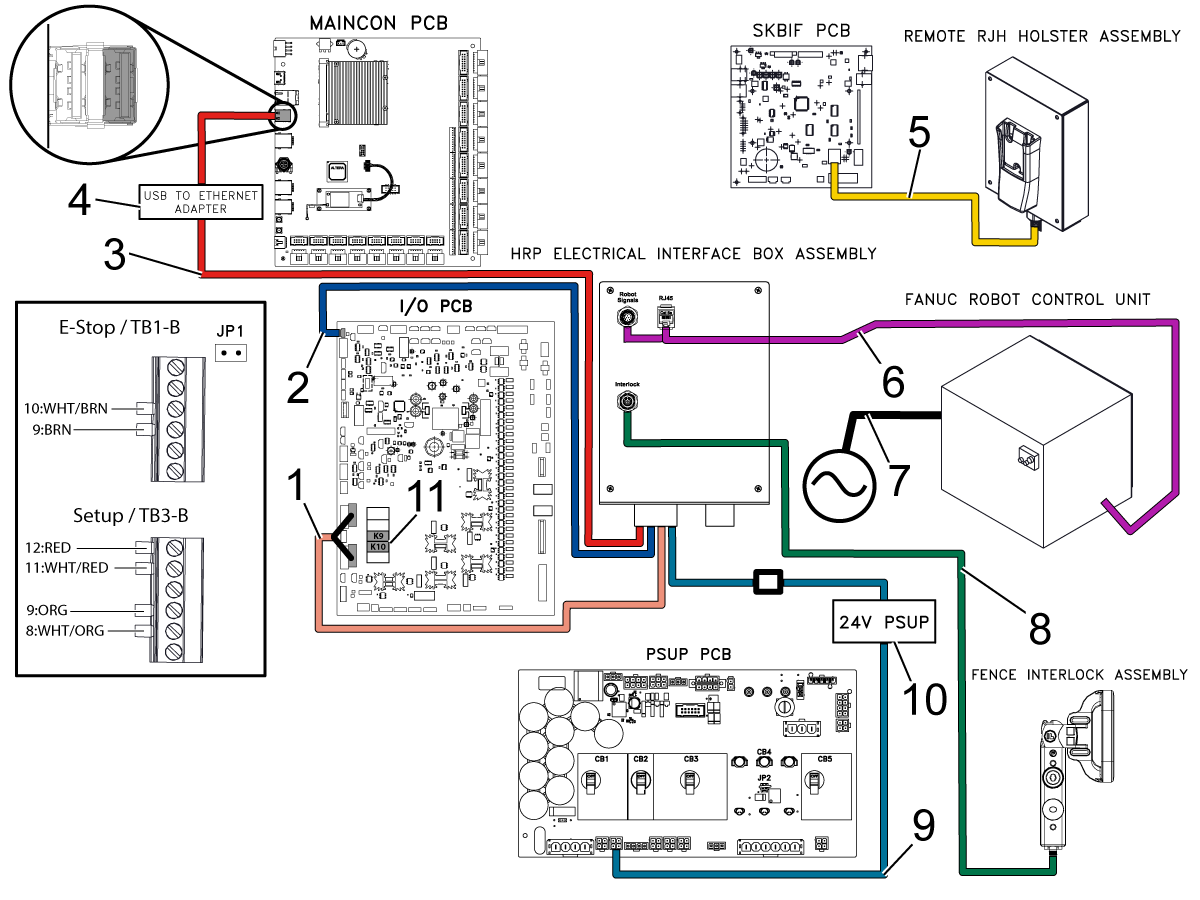
Electrical Diagrams

HRP-1 Wiring Diagram


HRP-2/3 Wiring Diagram

Feedback
FIND DISTRIBUTOR
Feedback
Haas Logo

美元价格不包括关税、报关费用、保险费、增值税及运费。
USD prices DO NOT include customs duty, customs fees, insurance, VAT, or freight.

人民币价格包含关税、报关费用、货运保险和增值税, 但不包括运费。
CNY prices include customs duty, customs fees, insurance, and VAT. DOES NOT include freight.

Haas Delivered Price

This price includes shipping cost, export and import duties, insurance, and any other expenses incurred during shipping to a location in France agreed with you as a buyer. No other mandatory costs can be added to the delivery of a Haas CNC Product.

KEEP UP WITH THE LATEST HAAS TIPS AND TECHNOLOGY...

Sign up now!   

HAAS TOOLING ACCEPTS THE FOLLOWING:

  • Service & Support
  • Owners
  • Request Service
  • Operator Manuals
  • Haas Parts
  • Rotary Repair Request
  • Pre-Install Guides
  • Shopping Tools
  • Build & Price a New Haas
  • Available Inventory
  • The Haas Price List
  • CNCA Financing
  • About Haas
  • Careers
  • Certifications & Safety
  • Contact Us
  • History
  • Terms & Conditions
  • Haas Tooling Terms & Conditions
  • Privacy
  • Warranty
  • Haas Community
  • Haas Certification Program
  • Haas Motorsports
  • Gene Haas Foundation
  • Haas Technical Education Community
  • Events
  • Join the Conversation
  • Facebook
  • Twitter
  • Flickr
  • YouTube
  • LinkedIn
  • Instagram
  • TikTok
© 2023 Haas Automation, Inc – CNC Machine Tools

This site is protected by reCAPTCHA and the Google Privacy Policy and Terms of Service apply.


2800 Sturgis Rd., Oxnard, CA 93030 / Toll Free: 800-331-6746
Phone: 805-278-1800 / Fax: 805-278-2255

Cookie Notice

We use cookies to improve your user experience. Our Cookie Notice describes which cookies we use, why we use them, and how you can find more information about them. Please confirm you consent to us using analytics cookies. If you do not consent, you may still use our website with a reduced user experience.

Manage Settings

Cookie Notice

We use cookies to improve your user experience. Our Cookie Notice describes which cookies we use, why we use them, and how you can find more information about them. Please confirm you consent to us using analytics cookies. If you do not consent, you may still use our website with a reduced user experience.

Functional Cookies

Analytics Cookies