My Haas Welcome,
!
Haas Tooling MyHaas/HaasConnect Sign In Register Haas Tooling MyHaas/HaasConnect Sign Out Welcome, My Machines Latest Activity My Quotes My Account My Users Sign Out
Find Your Distributor
  1. Select Language
    1. English
    2. Deutsch
    3. Español - ES
    4. Español - MX
    5. Français
    6. Italiano
    7. Português
    8. Český
    9. Dansk
    10. Nederlands
    11. Magyar
    12. Polski
    13. Svenska
    14. Türkçe
    15. 中文
    16. Suomi
    17. Norsk
    18. الإنجليزية
    19. български
    20. Hrvatski
    21. Ελληνικά
    22. Română
    23. Slovenský
    24. Slovenščina
    25. 한국어
    26. 日本語
    27. Українська
  • machines Main Menu
    • Vertical Mills
      Vertical Mills
      Vertical Mills View All
      • Vertical Mills
      • VF Series
      • Universal Machines
      • VR Series
      • VP-5 Prismatic
      • Pallet-Changing VMCs
      • Mini Mills
      • Mold Machines
      • High-Speed Drill Centers
      • Drill/Tap/ Mill Series
      • Toolroom Mills
      • Pocket Mill
      • Compact Mills
      • Gantry Series
      • SR Sheet Routers
      • Extra-Large VMC
      • Double-Column Mills
      • 3+2 Positioning Machines
    • Multi-Axis Solutions
      Multi-Axis Solutions
      Multi-Axis Solutions View All
      • Multi-Axis Solutions
      • Y-Axis Lathes
      • 5-Axis Mills
    • Lathes
      Lathes
      Lathes View All
      • Lathes
      • ST Series
      • Dual-Spindle
      • Box Way Series
      • Toolroom Lathes
      • Chucker Lathe
      • Pocket Lathe
      • Haas Bar Feeders
    • Horizontal Mills
      Horizontal Mills
      Horizontal Mills View All
      • Horizontal Mills
      • 50-Taper
      • 40-Taper
    • Rotaries & Indexers
      Rotaries & Indexers
      Rotaries & Indexers View All
      • Rotaries & Indexers
      • Rotary Tables
      • Indexers
      • 5-Axis Rotaries
      • Extra-Large Rotaries
    • Special Series
      Special Series
      Special Series View All
      • Special Series
      • EU_Series_Redirect
    • Automation Systems
      Automation Systems
      Automation Systems View All
      • Automation Systems
      • Mill Automation
      • Lathe Automation
      • Automatic Parts Loaders
      • Automation Models
    • Desktop Machines
      Desktop Machines
      Desktop Machines View All
      • Desktop Machines
      • Desktop Mill
      • Desktop Lathe
      • Control Simulator, Standard
      • Control Simulator, Premium
    • Shop Equipment
      Shop Equipment
      Shop Equipment View All
      • Shop Equipment
      • Knee Mill
      • Haas Manual Lathes
      • Haas Saws
    • Fabrication Machines
      Fabrication Machines
      Fabrication Machines View All
      • Fabrication Machines
      • Laser Cutting Machines
      • CNC Press Brakes
    • QUICK LINKS Special Series  Special Series 
      EU SERIES EU SERIES BUILD & PRICE | PRICE LIST BUILD & PRICE | PRICE LIST In-Stock Machines In-Stock Machines WHAT’S NEW WHAT’S NEW YOUR FIRST CNC YOUR FIRST CNC
      SHOPPING TOOLS
      • Build & Price a Haas
      • Price List
      • Available Inventory
      • CNCA Financing
      WANT TO TALK TO SOMEONE?

      A Haas Factory Outlet (HFO) can answer your questions, and walk you through your best options.

      CONTACT YOUR DISTRIBUTOR >
  • Options Main Menu
    • The Haas Control Value Option Packages
      Value Option Packages
      Value Option Packages View All
      • Value Option Packages
    • Product Image Spindles
      Spindles
      Spindles View All
      • Spindles
    • Product Image Tool Changers
      Tool Changers
      Tool Changers View All
      • Tool Changers
    • Product Image 4th- | 5th-Axis
      4th- | 5th-Axis
      4th- | 5th-Axis View All
      • 4th- | 5th-Axis
    • Product Image Turrets & Live Tooling
      Turrets & Live Tooling
      Turrets & Live Tooling View All
      • Turrets & Live Tooling
    • Product Image Probing
      Probing
      Probing View All
      • Probing
    • Haas Chip & Coolant Management Chip & Coolant Management
      Chip & Coolant Management
      Chip & Coolant Management View All
      • Chip & Coolant Management
    • The Haas Control The Haas Control
      The Haas Control
      The Haas Control View All
      • The Haas Control
    • Product Image Product Options
      Product Options
      Product Options View All
      • Product Options
    • Product Image Tooling & Fixturing
      Tooling & Fixturing
      Tooling & Fixturing View All
      • Tooling & Fixturing
    • Product Image Workholding
      Workholding
      Workholding View All
      • Workholding
    • Product Image 5-Axis Solutions
      5-Axis Solutions
      5-Axis Solutions View All
      • 5-Axis Solutions
      • 5 Easy Steps to 5-Axis
    • QUICK LINKS Special Series  Special Series 
      EU SERIES EU SERIES BUILD & PRICE | PRICE LIST BUILD & PRICE | PRICE LIST In-Stock Machines In-Stock Machines WHAT’S NEW WHAT’S NEW YOUR FIRST CNC YOUR FIRST CNC
      SHOPPING TOOLS
      • Build & Price a Haas
      • Price List
      • Available Inventory
      • CNCA Financing
      WANT TO TALK TO SOMEONE?

      A Haas Factory Outlet (HFO) can answer your questions, and walk you through your best options.

      CONTACT YOUR DISTRIBUTOR >
  • Why Haas Main Menu
      Discover the Haas Difference
    • Why Haas
    • MyHaas
    • Education Community
    • Industry 4.0
    • Haas Certification
    • Customer Testimonials
  • Service Main Menu
      Welcome to Haas Service
      SERVICE HOME Operator’s Manuals How-To Procedures Troubleshooting Guides Preventive Maintenance Haas Parts Haas Tooling Videos
  • Videos Main Menu
  • Main Menu
    • View All
    • View All
    • View All
    • View All
      • HTEC Curriculum Support
      • Haas Value Option Packages (VOP) Journey
    • View All
      • Haas 10 kg Cobot Package
      • Cobot Kits
      • DC-1 Drill Center
      • CNC Sales News
      • Do More With Your Haas
    • View All
    • View All
      • contact-us-test
      • 4 - AUTOMATION SYSTEMS
      • Carousel-V2
      • expert test
      • Demo_Day_Trident-test
      • Link Test
      • image-sale-tag-test
      • article-list-test
      • Haas 25 kg Robot Package
      • test-algolia-page
    • View All
    • View All
    • View All
    • View All
      • calc-test
    • View All
    • QUICK LINKS Special Series  Special Series 
      EU SERIES EU SERIES BUILD & PRICE | PRICE LIST BUILD & PRICE | PRICE LIST In-Stock Machines In-Stock Machines WHAT’S NEW WHAT’S NEW YOUR FIRST CNC YOUR FIRST CNC
      SHOPPING TOOLS
      • Build & Price a Haas
      • Price List
      • Available Inventory
      • CNCA Financing
      WANT TO TALK TO SOMEONE?

      A Haas Factory Outlet (HFO) can answer your questions, and walk you through your best options.

      CONTACT YOUR DISTRIBUTOR >
  • Haas Tooling Main Menu
  • Haas Service Parts Main Menu

My Haas Welcome,
!
Haas Tooling MyHaas/HaasConnect Sign In Register Haas Tooling MyHaas/HaasConnect Sign Out Welcome, My Machines Latest Activity My Quotes My Account My Users Sign Out
Find Your Distributor
  1. Select Language
    1. English
    2. Deutsch
    3. Español - ES
    4. Español - MX
    5. Français
    6. Italiano
    7. Português
    8. Český
    9. Dansk
    10. Nederlands
    11. Magyar
    12. Polski
    13. Svenska
    14. Türkçe
    15. 中文
    16. Suomi
    17. Norsk
    18. الإنجليزية
    19. български
    20. Hrvatski
    21. Ελληνικά
    22. Română
    23. Slovenský
    24. Slovenščina
    25. 한국어
    26. 日本語
    27. Українська
×

Search Results

Web Pages

Images

    • <
    • 1
    • >

10 - HRP - FANUC DCS Setup

Haas Robot Package - Operator's/Service Manual


  • 0 - HRP - Table of Contents
  • 1 - HRP - Introduction
  • 2 - HRP - Legal Information
  • 3 - HRP - Safety
  • 4 - HRP-7kg - Installation
  • 5 - HRP-25kg - Installation
  • 6 - HRP-50kg - Installation
  • 7 - HRP - Fence/Interlock Installation
  • 8 - HRP - Area Scanner Installation
  • 9 - HRP - Light Curtain Installation
  • 10 - HRP - FANUC DCS Setup
  • 11 - HRP - Operation
  • 12 - HRP - Maintenance
  • 13 - HRP - Troubleshooting

Go To :

  • 10.1 HRP DCS Setup
Recently Updated

Haas Robot – FANUC Dual Check Safety (DCS) – Setup


Revision A - 4/2025

Introduction

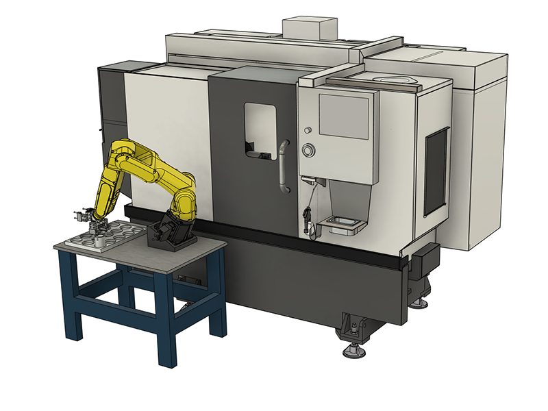
Each Haas Robot is provided with FANUC's DCS System. This allows the user to define speed and positional limits to the robot. If the robot goes outside of these limits, DCS will stop the robot and remove power to the motors.

This guide will show how to configure a simple Cartesian Position Check limits for your robot. The Cartesian Position Check Function allows a user to define a work zone and a restricted zone for the robot. If the robot exits a defined work zone then DCS will stop the robot. If any part of the robot violates a restricted zone, then DCS will stop the robot. The user must jog the robot back to it's work zone, or out of the restricted zone at a reduced speed or the robot will alarm out.

The Robot Package comes pre-configured with Cartesian Speed Check limits for RUN and SETUP mode.

Note: Verify proper setup of the DCS zones at the time of robot installation and every 6 months. It should also be verified after a new job has been set up.

These instructions require that your robot be aligned with your fence. 

Note: If the robot was not aligned with the fence, the work zone will be smaller than expected.

Important: Before continuing with the DCS procedure, verify the robot is orientated the correct way.

This procedure shows images and an example of the HRP-1, but it can be used and followed for HRP-2 and HRP-3.

Measuring Safe Zone Size

1

The work zone size will be referenced and measured from the center of J2 axis of the robot. One surface and one edge from J2 we will measure from in order to get the center of J2. If using the flat from surface A, we will add 4.5in or 114mm to our measurements. If using surface B, we will add 2.5in or 63.5mm to our measurements.

Turn on machine and robot, make sure both are connected to each other. Jog the J1 robot axis so that it is at 90, 0 or -90 degrees. Your robot surfaces A and B should now be parallel to the fence and machine door.

2

Cut out the XY coordinate system and place it on your robot table to help visualize where we are taking measurements in relation to the coordinate system.

The coordinate system for your application will depend on how your robot is positioned on the table. The side of the robot base with power cables coming out is the X- direction. The battery cover on the base of the robot is the Y+ direction.

Note: This coordinate system is considered to be the world frame. World frame in this application is rotated along Y by -30 degrees because of the way the robot base is mounted on the tilt mount. Later in the steps we will be assigning a user frame for this safe zone that will have a simple 30 degree Y rotation which will cancel out the physical tilt of the base.

Align the coordinate system reference with the XY direction of your robot setup.

3

Use the table provided to fill in your measurements.

Note: All dimensions will need to be converted to millimeters.

Make sure to measure the distances with the measuring tape parallel to the axis on the coordinate system print out.

Note: There will be one positive and one negative value for X, Y and Z.

*These dimensions are for HRP-1. These Z distances can be adjusted for more clearance above and below the robot. This value is measured from the center of J2.

4

Warning: The following dimensions are an example and should not be used for DCS Setup.

Measure the distance from the center of J2 to the fence on opposite of the machine. This is the negative Y-direction when referencing the coordinate system print out.

Example: The distance of the negative Y-direction for point 1 is 24.5” this is calculated as:

  • The edge of J2 to the center of J2 = +4.5” [2]
  • The edge of J2 to the fence = +20.0” [1]

Enter the total distance into the table corresponding to the direction of measurement. The Y-axis in the negative direction was measured. The value is entered into the table in the Y row and Point 1 column. The dimension will have a negative value.

5

Measure the distance from the center of J2 axis to the fence. This is the negative X-direction when referencing the coordinate system print out.

Example: The distance of the negative X-direction for point 1 is -34.5”, this is calculated as:

  • The edge of J2 to the center of J2 = -2.5” [2]
  • The edge of J2 to the fence = -32.0” [1]

Enter the total distance into the table corresponding to the direction of measurement. The X-axis in the negative direction was measured. The value is entered into the table in the X row and Point 1 column. The dimension will have a negative value.

6

Measure the distance from the center of J2 to the inside of the machine past the workholding. This is the positive Y-direction when referencing the coordinate system print out.

Example: The distance of the positive Y-direction for point 2 is -39.5” this is calculated as:

  • The edge of J2 to the center of J2 = -4.5” [2]
  • The edge of J2 to the face of the closed door = -11.0” [1]
  • The face of the open door to past the workholding = -24.0" [3] 

Enter the total distance into the table corresponding to the direction of measurement. The Y-axis in the positive direction was measured. The value is entered into the table in the Y row and Point 2 column. The dimension will have a positive value.

Note: If this safe zone measurement is incorrectly calculated. The safe zone may be placed too close to work holding. This value can be adjusted to add more work space inside the machine.

7

Measure the distance from the center of J2 axis to the edge of the door opening. This is the positive X-direction when referencing the coordinate system print out.

Example: The distance of the positive X-direction for point 2 is 28.5”, this is calculated as:

  • The edge of J2 to the center of J2 = 2.5” [2]
  • The edge of J2 to the edge of the door opening = 26.0”  [1]

Enter the total distance into the table corresponding to the direction of measurement. In the case above, the X+ axis was measured, so the value would go into point 2 with a positive value.

8

The Z value for each point is in the table. If more ceiling work envelope is needed, the positive Z distance can be increased. If more floor work envelope is needed, the negative Z distance can be increased.

After taking measurements, double check values. The values are creating a box around the robot that is referenced from the center of J2.

DCS User Frame Setup

Haas Robot - Connect to iPendant

1

To setup a DCS User Frame, a computer with internet access will need to be connected to the Robot Control Box with a RJ-45 cable. Open the front door of your robot controller and unplug the RJ-45 cable from Port 1 [1]. Plug in a new RJ-45 cable that is connected to a computer that has internet access. Follow the video above to setup the adapter settings on your computer to match the robot IP address.

Note: When finished setting up the DCS User frame, disconnect the RJ-45 cable from the computer and robot and plug the RJ-45 back into the Port 1.

2

Login to the HMI Jogging Pendant from your web browser.

Navigate to the User Frame Setup view.

Click on Frame 9 then click DETAIL.


3

For Robot Package 1 VF/VM & ST Machines Only

Select P and enter the value of -30.0, and then hit enter on your keyboard.

This number adds a negative 30 degree rotation about the Y-Axis to the world frame. This cancels out the tilt of the robot base.

4

For Robot Package 2 Machines Only

Select R and enter the value from the table below for the specific machine,  and then hit enter on your keyboard.

This number adds a negative amount of rotation (in degrees) about the Z-Axis to the world frame. This cancels out the rotation of the robot base.

Note: The image shows an R rotation value for a certain machine layout. This value does not apply to all machine layouts. Enter the value from the table below for the specific machine layout.

Machine

Robot With Weldment Base R Rotation Angle

Robot With Cast Base R Rotation Angle UMC Robot Base Plate R Rotation Angle

ST-20/25 & VF-5

-32.14 -42.91 N/A

ST-20L/25L/30L/35L & VF-1/2/3/4

-36.5 -45.23 N/A
ST-30/35 -40.35 -47.46 N/A
UMC-500/750/1000/1250 N/A N/A -35

5

Navigate to DCS Menu.

Enable the pendant by hitting the ON/OFF button on the top right.

Enter user frame section (10).

Select the second zero in the list under No. column and press 9. Confirmation question will show at the bottom, press YES. Change that value to 9 after confirmation.

You should see P or R populate with the same value from step 3 or 4.

Go back to DCS menu.

Disable DCS Unused Position and Speed Limit Checks

Cartesian Speed Check, Joint Position Check, and Joint Speed Check need to be disabled. They may be enabled as default. If the setting are not disabled, alarm 9150.403 SRVO-403 DCS Cart. speed limit, 9150.404 SRVO-404 DCS Joint pos. limit, or 9150.405 SRVO-405 DCS Joint speed limit will be generated. Follow the steps below to disable these settings.

1

Login to the HMI Jogging Pendant from your web browser.

Navigate to the User Frame Setup view.

Navigate to DCS Menu.

Enable the pendant by hitting the ON/OFF button on the top right.

2

Go into the enabled settings. Joint Position Check (3), Joint Speed Check (4), and Cart. Speed Check (6).

Go into No. 1.

Disable the position check No. 1 by selecting then pressing [CHOICE] at the bottom.

Press PREV 3 times to get back to the Main DCS screen.

3

Now we will apply the all the changes we made in the DCS menu. Any DCS section that was changed since last APPLY will show a RED CHGD next to it. Press APPLY at the bottom.

Enter 1111 for the Master Code.

This will take you to another menu that will show you the changes made in the DCS menu since last apply. Press OK if all changes are correct.

Close the HMI Pendant Window.

Cycle power on the robot controller by turning the power switch OFF, waiting 5 seconds then back ON.

DCS Cartesian Position Check Setup

1

Go into Cart. Position Check (5).

Go into No. 1.

Enable the position check No. 1 by selecting then pressing [CHOICE] at the bottom.

Change the Method type to Work Zone (Diagonal) by clicking the row then selecting [CHOICE] at the bottom.

Target Model 1 should say Robot Model, Target model 2 and 3 should be disabled.

Set Base Frame: User Frame: to 9 by selecting then entering 9.

2

In Point 1 and 2, enter in the values that were recorded from earlier in the guide. This is where we define the two points for the work space diagonal box.

For Stop Type, click the row then select [CHOICE] at the bottom and change to Speed Check(1).

Make sure Stop Prediction is Yes.

Click on <DETAIL> under Speed Check then hit ENTER on your keyboard.

Set Limit 1 to 20.0, Delay Time to 0, and Permissable distance to 0.0, Speed Control to DISABLE.

Press PREV 3 times to get back to the Main DCS screen.

3

Now we will apply the all the changes we made in the DCS menu. Any DCS section that was changed since last APPLY will show a RED CHGD next to it. Press APPLY at the bottom.

Enter 1111 for the Master Code.

This will take you to another menu that will show you the changes made in the DCS menu since last apply. Press OK if all changes are correct.

Close the HMI Pendant Window.

Cycle power on the robot controller by turning the power switch OFF, waiting 5 seconds then back ON.

Setup is complete. There is now a work zone setup around the robot. If any part of the robot leaves the work zone at a speed greater than 20mm/s, it will alarm. If this alarm is triggered, it is possible to reset the alarm and jog back into the zone at a rate less than 20mm/s. The next section covers how to visualize the zone that was just created.

DCS Cartesian Position Visualization

1

With the Work Zone setup, we want a way to visualize the zone in relation to the robot.

Access the Jogging HMI Pendant and navigate to MENU > NEXT > 4D Graphics.

You will see the robot virtually on the HMI pendant along with its current orientation.

To see the DCS zone, click on [VISIBLE] at the bottom bar, if it is not there, press the > arrow on the bar.

2

A new menu will display in the top left of the 4D display. Click on 4D DCS Display, it will turn a shade of blue to signify that it is ON. You will see a box appear if your DCS zone is enabled and setup.

Verify that the work zone that appears is surrounding your robot. If the zone is a shade of red, that means a part of the robot is outside of the zone. If the zone is green that means your robot is within the zone.

This display will update in real time, you can have this open on your laptop/computer while you jog the robot with the HAAS machine.

This zone can be modified with the Point 1 and Point 2 XYZ positions from step. It is OK if the zone is angled in the 4D display, because the robot base is angled in real world (in our application).

DCS Cartesian Position Verification

1

Note: When finished setting up the DCS User frame, disconnect the RJ-45 cable from the computer and robot and plug the RJ-45 back into the Port 1.

Verify the DCS zone by jogging the robot in the positive Y-direction to a safe location out of the DCS zone and check if the machine alarms.

If it does, jog back into the DCS zone.

Note: To jog back into the DCS zone without alarming the machine, lower the jogging feedrate.

Feedback

Recently Viewed Items

You Have No Recently Viewed Items Yet

Feedback
Haas Logo

Haas Delivered Price

This price includes shipping cost, export and import duties, insurance, and any other expenses incurred during shipping to a location in France agreed with you as a buyer. No other mandatory costs can be added to the delivery of a Haas CNC Product.

KEEP UP WITH THE LATEST HAAS TIPS AND TECHNOLOGY...

Sign up now!   

HAAS TOOLING ACCEPTS THE FOLLOWING:

  • Service & Support
  • Owners
  • Request Service
  • Operator Manuals
  • Haas Parts
  • Rotary Repair Request
  • Pre-Install Guides
  • Shopping Tools
  • Build & Price a New Haas
  • Available Inventory
  • The Haas Price List
  • CNCA Financing
  • About Haas
  • Accessibility Statement
  • DNSH Statement
  • Export Compliance
  • Careers
  • Certifications & Safety
  • Contact Us
  • History
  • Terms & Conditions
  • Haas Tooling Terms & Conditions
  • Privacy
  • Warranty
  • Haas Community
  • Haas Certification Program
  • Haas Motorsports
  • Gene Haas Foundation
  • Haas Technical Education Community
  • Events
  • Join the Conversation
  • Facebook
  • X
  • Flickr
  • YouTube
  • LinkedIn
  • Instagram
  • TikTok
© 2026 Haas Automation, Inc – CNC Machine Tools

This site is protected by reCAPTCHA and the Google Privacy Policy and Terms of Service apply.

2800 Sturgis Rd., Oxnard, CA 93030
Toll Free: (888) 817-4446 / Fax: 805-278-8554