-
기계
-
옵션
-
 스핀들
스핀들
스핀들
스핀들 -
 공구 교환장치
공구 교환장치
공구 교환장치 -
 4 | 5축
4 | 5축
4 | 5축 -
 터렛 및 라이브 툴링
터렛 및 라이브 툴링
터렛 및 라이브 툴링 -
 검사
검사
검사
검사 -
 칩 및 절삭유 관리
칩 및 절삭유 관리
칩 및 절삭유 관리 -
 Haas Control
Haas Control
Haas Control -
 제품 선택 사항
제품 선택 사항
제품 선택 사항 -
 툴링 및 픽스처링
툴링 및 픽스처링
툴링 및 픽스처링 -
 워크홀딩
워크홀딩
워크홀딩
워크홀딩 -
 5축 솔루션
5축 솔루션
5축 솔루션 -
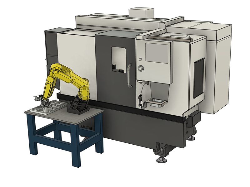
 자동화
자동화
자동화
자동화
상담을 받고 싶으신가요?Haas Factory Outlet (HFO)은 고객님의 질문에 답변을 드리며 가장 좋은 선택지를 안내해 드립니다.
CONTACT YOUR DISTRIBUTOR > -
-
Why Haas
Haas의 차이를 알아보세요
-
서비스
- 동영상


-setup/Machines-Top-View.png)
-setup/FANUC%20DCS%20Safe%20Zone%20Setup%20J2%20Measuring%201.jpg)
-setup/step-2.png)
-setup/Table.jpg)
-setup/step-4.png)
-setup/step-5.png)
-setup/step-6.png)
-setup/step-7.png)
-setup/step-8.png)
-setup/DCS-User-Frame-Setup-1.png)
-setup/DCS-User-Frame-30-degree-Y-axis.png)
-setup/DCS-User-Frame-35-degree-Z-axis.png)
-setup/DCS-User-Frame-Setup-2-2.png)
-setup/DCS-Cartesian-Position-Check-Setup-1.png)
-setup/DCS-Cartesian-Position-Check-Setup-2.png)
-setup/DCS-Cartesian-Position-Check-Setup-3-2.png)
-setup/DCS-Cartesian-Position-Visualization-1.png)
-setup/HMI%20iPendant%2034.jpg)
-setup/Verify-DCS-Zone-Jogging.png)