-
machines
-
Fraiseuses verticales
Fraiseuses verticales
-
Solutions multi-axes
Solutions multi-axes
-
Tours
Tours
-
Fraiseuses horizontales
Fraiseuses horizontales
-
Tables rotatives et indexeurs/diviseurs
Tables rotatives et indexeurs/diviseurs
-
Systèmes d’automatisation
Systèmes d’automatisation
-
Machines de bureau
Machines de bureau
-
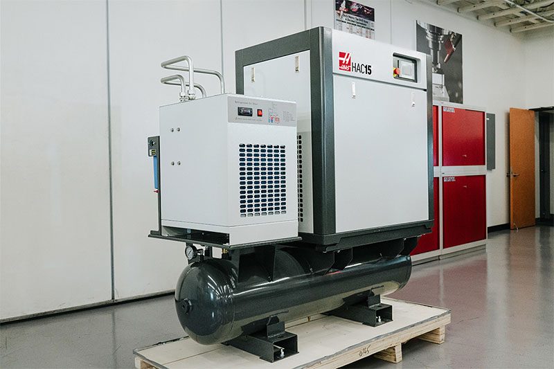
Équipement d’atelier
Équipement d’atelier
-
Machines de poche
Machines de poche
OUTILS D'ACHATVOUS SOUHAITEZ PARLER À UN AGENT ?Un magasin d’usine Haas (HFO) peut répondre à vos questions et vous présenter les meilleures options.
CONTACT YOUR DISTRIBUTOR > -
Fraiseuses verticales
-
Options
-
 Broche
Broche
Broche -
 Changeurs d’outils
Changeurs d’outils
Changeurs d’outils -
 4e et 5e axes
4e et 5e axes
4e et 5e axes -
 Tourelles et outil Tournant
Tourelles et outil Tournant
Tourelles et outil Tournant -
 Palpage
Palpage
Palpage -
 Gestion des copeaux et du liquide de coupe
Gestion des copeaux et du liquide de coupe
Gestion des copeaux et du liquide de coupe -
 La commande Haas
La commande Haas
La commande Haas -
 Options de produit
Options de produit
Options de produit -
 Outillage et montages d’outillages de fixation
Outillage et montages d’outillages de fixation
Outillage et montages d’outillages de fixation -
 Dispositifs de serrage de pièces
Dispositifs de serrage de pièces
Dispositifs de serrage de pièces -
 Solutions à 5 axes
Solutions à 5 axes
Solutions à 5 axes -
 Automatisation
Automatisation
Automatisation
OUTILS D'ACHATVOUS SOUHAITEZ PARLER À UN AGENT ?Un magasin d’usine Haas (HFO) peut répondre à vos questions et vous présenter les meilleures options.
CONTACT YOUR DISTRIBUTOR > -
-
Why Haas
Découvrez la différence Haas
-
Service
Bienvenue au Haas Service
- Vidéos
-
Outillage Haas
- Outillage Haas
-
Winner's Circle
-
Winner's Circle
-
Les bonnes affaires du jour
-
Liquidation
-
Mesure et inspection
-
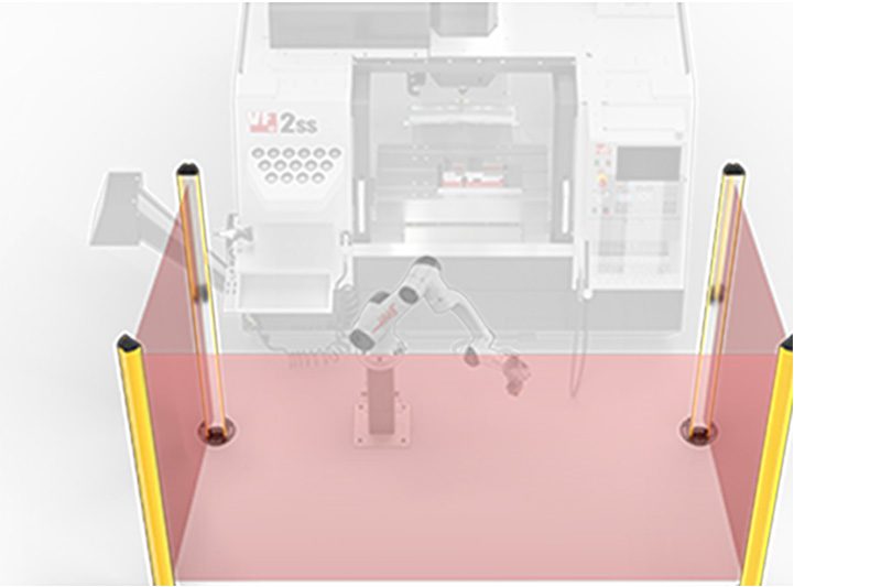
Cobots et accessoires
-
Acheter des supports
-
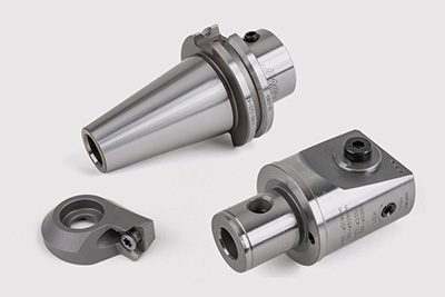
Porte-outils de fraiseuse
-
Outillage pour fraisage
-
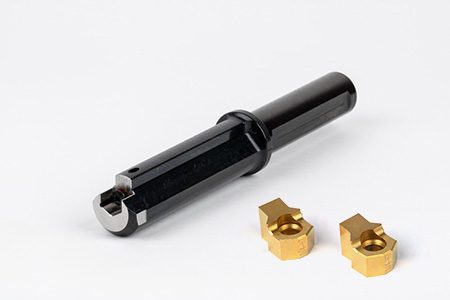
Systèmes d’alésage
-
Dispositif de serrage de la pièce pour la fraiseuse
-
Porte-outils pour tours
-
Outillage de tour
-
Dispositif de serrage de pièces pour tour
-
Kits pack
-
Mandrins et pinces de serrage ER
-
Perçage
-
Filetage
-
Brochage
-
Pierres tombales
-
Mandrins manuels pour fraisage
-
Ébavurage et abrasifs
-
Dispositif de préréglage d’outil et dispositif de frettage à chaud
-
Stockage d’outils
-
Maintenance de la machine
-
Accessoires d’outillage
-
Vêtements et accessoires
 Accessoires d’automatisation
 Assistance achat
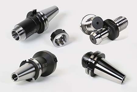 Porte-outils pour fraiseuse
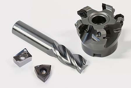 Outils coupants de fraiseuses
 Systèmes d’alésage
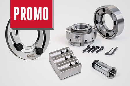
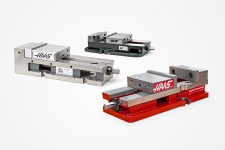 Dispositif de serrage de la pièce pour la fraiseuse
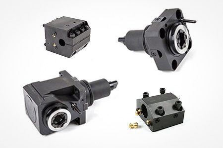 Porte-outil de tour
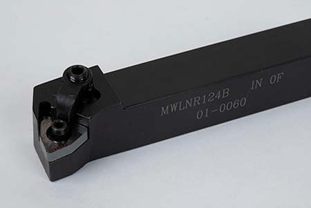 Outils coupant de tours
 Dispositif de serrage de la pièce de tour
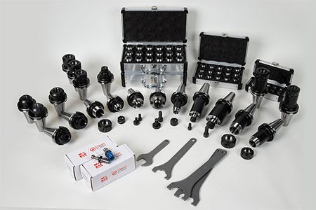 Kits pack
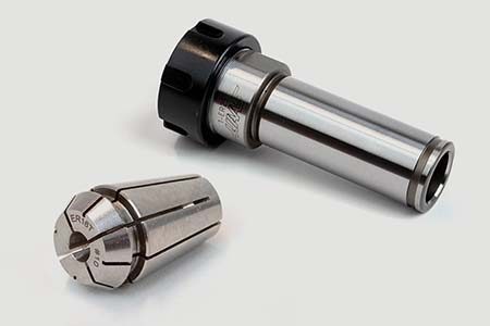 Mandrin à pinces ER
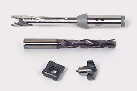 Perçage
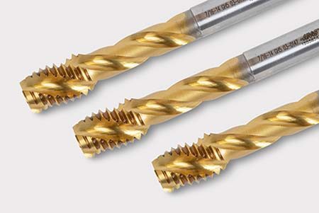 Filetage
 Brochage
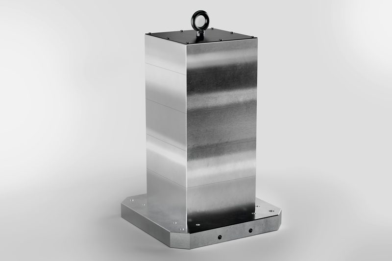 Cubes de serrage et kits
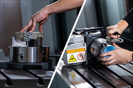 Mandrin manuel pour fraisage
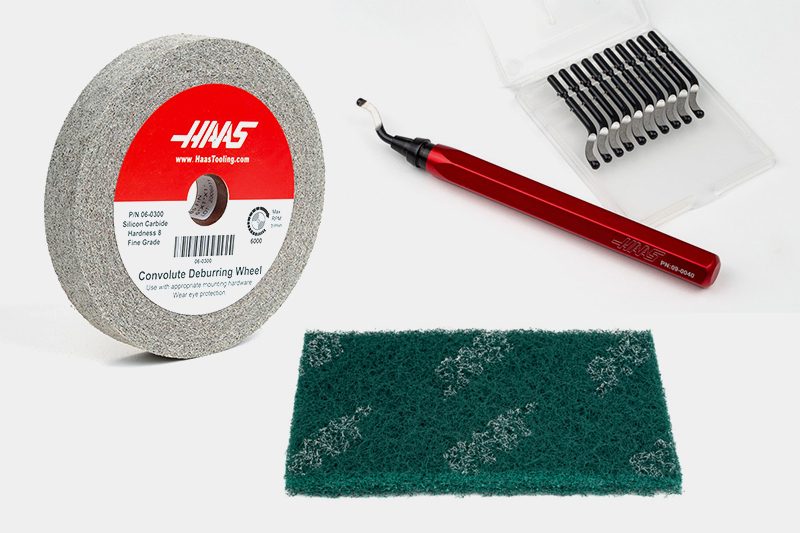 Ébavurage et abrasifs
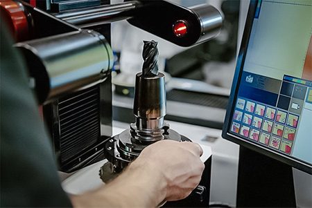 Dispositif de préréglage d’outil et dispositif de frettage à chaud
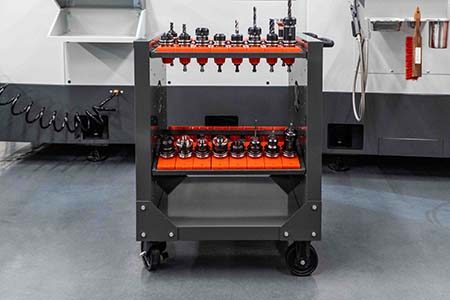 Stockage et manipulations de pièces
 Entretien de la machine
 Accessoires d’outillage
 Vêtements et accessoires
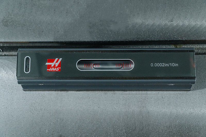
 Mesure & Inspection
 Winner's Circle
Winner's Circle
Winner's Circle
 Liquidation
 Les bonnes affaires du jour


-setup/Machines-Top-View.png)
-setup/FANUC%20DCS%20Safe%20Zone%20Setup%20J2%20Measuring%201.jpg)
-setup/step-2.png)
-setup/Table.jpg)
-setup/step-4.png)
-setup/step-5.png)
-setup/step-6.png)
-setup/step-7.png)
-setup/step-8.png)
-setup/DCS-User-Frame-Setup-1.png)
-setup/DCS-User-Frame-30-degree-Y-axis.png)
-setup/DCS-User-Frame-35-degree-Z-axis.png)
-setup/DCS-User-Frame-Setup-2-2.png)
-setup/DCS-Cartesian-Position-Check-Setup-1.png)
-setup/DCS-Cartesian-Position-Check-Setup-2.png)
-setup/DCS-Cartesian-Position-Check-Setup-3-2.png)
-setup/DCS-Cartesian-Position-Visualization-1.png)
-setup/HMI%20iPendant%2034.jpg)
-setup/Verify-DCS-Zone-Jogging.png)