-
機械
クイックリンク 特殊シリーズ 特殊シリーズショッピングツール
- オプション
-
Why Haas
Haasの特徴を見る
-
サービス
Haasサービスへようこそ
- ビデオ
-
MyHaas - すべてをひとつの場所で

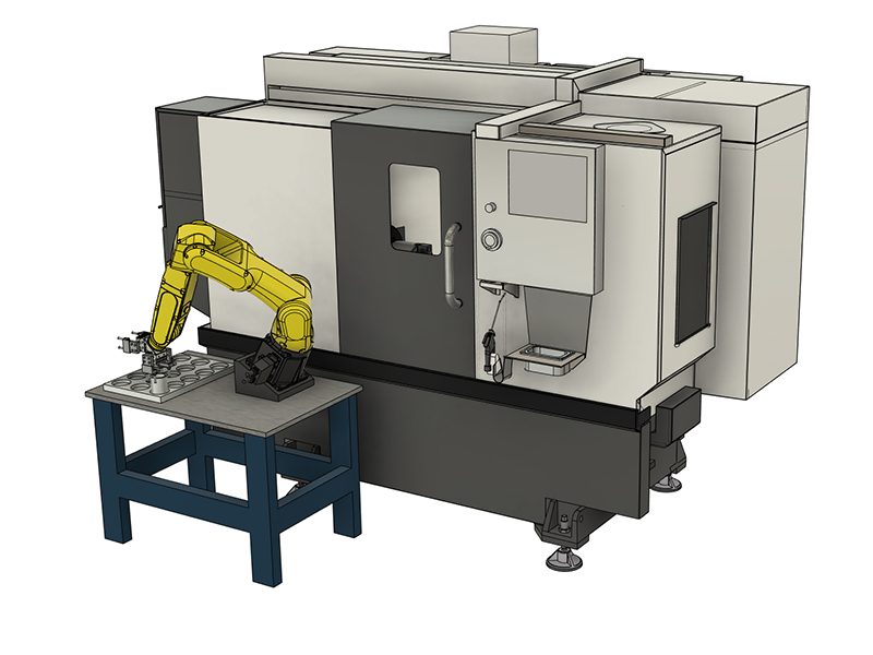
Each Haas Robot is provided with FANUC's DCS System. This allows the user to define speed and positional limits to the robot. If the robot goes outside of these limits, DCS will stop the robot and remove power to the motors.
This guide will show how to configure a simple Cartesian Positon Check limits for your robot. The Cartesian Position Check Function allows a user to define a work zone and a restricted zone for the robot. If the robot exits a defined work zone then DCS will stop the robot. If any part of the robot violates a restricted zone, then DCS will stop the robot. The user must jog the robot back to it's work zone, or out of the restricted zone at a reduced speed or the robot will alarm out.
The Robot Package comes pre-configured with Cartesian Speed Check limits for RUN and SETUP mode.
Note: Verify proper setup of the DCS zones at the time of robot installation and every 6 months. It should also be verified after a new job has been set up.
These instructions require that your robot be aligned with your fence.
Note: If the robot was not aligned with the fence, the work zone will be smaller than expected.
The work zone size will be referenced and measured from the center of J2 axis of the robot. One surface and one edge from J2 we will measure from in order to get the center of J2. If using the flat from surface A, we will add 4.5in or 114mm to our measurements. If using surface B, we will add 2.5in or 63.5mm to our measurements.
Turn on machine and robot, make sure both are connected to each other. Jog the J1 robot axis so that it is at 90, 0 or -90 degrees. Your robot surfaces A and B should now be parallel to the fence and machine door.
Cut out the XY coordinate system and place it on your robot table to help visualize where we are taking measurements in relation to the coordinate system.
The coordinate system for your application will depend on how your robot is positioned on the table. The side of the robot base with power cables coming out is the X- direction. The battery cover on the base of the robot is the Y+ direction.
Note: This coordinate system is considered to be the world frame. World frame in this application is rotated along X by -30 degrees because of the way the robot base is mounted on the tilt mount. Later in the steps we will be assigning a user frame for this safe zone that will have a simple 30 degree X rotation which will cancel out the physical tilt of the base.
Align the coordinate system reference with the XY direction of your robot setup.
Use the table provided to fill in your measurements.
Note: All dimensions will need to be converted to millimeters.
Make sure to measure the distances with the measuring tape parallel to the axis on the coordinate system print out.
Note: There will be one positive and one negative value for X, Y and Z.
*The Z distances can be adjusted for more clearance above and below the robot. This value is measured from the center of J2.
Warning: The following dimensions are an example and should not be used for DCS Setup.
Measure the distance from the center of J2 to the fence on opposite of the machine. This is the positive X-direction when referencing the coordinate system print out.
Example: The distance of the positive X-direction for point 1 is 24.5” this is calculated as:
Enter the total distance into the table corresponding to the direction of measurement. The X-axis in the positive direction was measured. The value is entered into the table in the X row and Point 1 column. The dimension will have a positive value.
Measure the distance from the center of J2 axis to the fence. This is the negative Y-direction when referencing the coordinate system print out.
Example: The distance of the negative Y-direction for point 1 is -34.5”, this is calculated as:
Enter the total distance into the table corresponding to the direction of measurement. The Y-axis in the negative direction was measured. The value is entered into the table in the Y row and Point 1 column. The dimension will have a negative value.
Measure the distance from the center of J2 to the inside of the machine past the workholding. This is the negative X-direction when referencing the coordinate system print out.
Example: The distance of the negative X-direction for point 2 is -39.5” this is calculated as:
Enter the total distance into the table corresponding to the direction of measurement. The X-axis in the negative direction was measured. The value is entered into the table in the X row and Point 2 column. The dimension will have a negative value.
Note: If this safe zone measurement is incorrectly calculated. The safe zone may be placed too close to work holding. This value can be adjusted to add more work space inside the machine.
Measure the distance from the center of J2 axis to the edge of the door opening. This is the positive Y-direction when referencing the coordinate system print out.
Example: The distance of the positive Y-direction for point 2 is 28.5”, this is calculated as:
Enter the total distance into the table corresponding to the direction of measurement. In the case above, the Y+ axis was measured, so the value would go into point 2 with a positive value.
The Z value for each point is in the table. If more ceiling work envelope is needed, the positive Z distance can be increased. If more floor work envelope is needed, the negative Z distance can be increased.
After taking measurements, double check values. The values are creating a box around the robot that is referenced from the center of J2.
To setup a DCS User Frame, a computer with internet access will need to be connected to the Robot Control Box with a RJ-45 cable. Open the front door of your robot controller and unplug the RJ-45 cable from Port 1 [1]. Plug in a new RJ-45 cable that is connected to a computer that has internet access. Follow the video above to setup the adapter settings on your computer to match the robot IP address.
Note: When finished setting up the DCS User frame, disconnect the RJ-45 cable from the computer and robot and plug the RJ-45 back into the Port 1.
Login to the HMI Jogging Pendant from your web browser.
Navigate to the User Frame Setup view.
Click on Frame 9 then click DETAIL.
For Robot Package 1 Only
Select W and enter the value of 30.0 then hit enter on your keyboard.
This is where we are adding a 30 degree X rotation to the world frame to cancel out the tilt of the robot base.
Navigate to DCS Menu.
Enable the pendant by hitting the ON/OFF button on the top right.
Enter user frame section (10).
Select the second zero in the list under No. column and press 9. Confirmation question will show at the bottom, press YES. Change that value to 9 after confirmation.
You should see W populate with the same value from step 2.
Go back to DCS menu.
Go into Cart. Position Check (5).
Go into No. 1.
Enable the position check No. 1 by selecting then pressing [CHOICE] at the bottom.
Change the Method type to Work Zone (Diagonal) by clicking the row then selecting [CHOICE] at the bottom.
Target Model 1 should say Robot Model, Target model 2 and 3 should be disabled.
Set Base Frame: User Frame: to 9 by selecting then entering 9.
In Point 1 and 2, enter in the values that were recorded from earlier in the guide. This is where we define the two points for the work space diagonal box.
For Stop Type, click the row then select [CHOICE] at the bottom and change to Speed Check(1).
Make sure Stop Prediction is Yes.
Click on <DETAIL> under Speed Check then hit ENTER on your keyboard.
Set Limit 1 to 20.0, Delay Time to 0, and Permissable distance to 0.0, Speed Control to DISABLE.
Press PREV 3 times to get back to the Main DCS screen.
Now we will apply the all the changes we made in the DCS menu. Any DCS section that was changed since last APPLY will show a RED CHGD next to it. Press APPLY at the bottom.
Enter 1111 for the Master Code.
This will take you to another menu that will show you the changes made in the DCS menu since last apply. Press OK if all changes are correct.
Close the HMI Pendant Window.
Cycle power on the robot controller by turning the power switch OFF, waiting 5 seconds then back ON.
Setup is complete. There is now a work zone setup around the robot. If any part of the robot leaves the work zone at a speed greater than 20mm/s, it will alarm. If this alarm is triggered, it is possible to reset the alarm and jog back into the zone at a rate less than 20mm/s. The next section covers how to visualize the zone that was just created.
With the Work Zone setup, we want a way to visualize the zone in relation to the robot.
Access the Jogging HMI Pendant and navigate to MENU > NEXT > 4D Graphics.
You will see the robot virtually on the HMI pendant along with its current orientation.
To see the DCS zone, click on [VISIBLE] at the bottom bar, if it is not there, press the > arrow on the bar.
A new menu will display in the top left of the 4D display. Click on 4D DCS Display, it will turn a shade of blue to signify that it is ON. You will see a box appear if your DCS zone is enabled and setup.
Verify that the work zone that appears is surrounding your robot. If the zone is a shade of red, that means a part of the robot is outside of the zone. If the zone is green that means your robot is within the zone.
This display will update in real time, you can have this open on your laptop/computer while you jog the robot with the HAAS machine.
This zone can be modified with the Point 1 and Point 2 XYZ positions from step. It is OK if the zone is angled in the 4D display, because the robot base is angled in real world (in our application).
Note: When finished setting up the DCS User frame, disconnect the RJ-45 cable from the computer and robot and plug the RJ-45 back into the Port 1.
Verify the DCS zone by jogging the robot in the positive Y-direction to a safe location out of the DCS zone and check if the machine alarms.
If it does, jog back into the DCS zone.
Note: To jog back into the DCS zone without alarming the machine, lower the jogging feedrate.
To make this site work properly, we sometimes place small data files called cookies on your device. Most big websites do this too.
A cookie is a small text file that a website saves on your computer or mobile device when you visit the site. It enables the website to remember your actions and preferences (such as login, language, font size and other display preferences) over a period of time, so you don’t have to keep re-entering them whenever you come back to the site or browse from one page to another.
美元价格不包括关税、报关费用、保险费、增值税及运费。
USD prices DO NOT include customs duty, customs fees, insurance, VAT, or freight.
人民币价格包含关税、报关费用、货运保险和增值税, 但不包括运费。
CNY prices include customs duty, customs fees, insurance, and VAT. DOES NOT include freight.
この価格には、送料、輸出入関税、保険、およびお客様が購入者として同意されたフランスの宛先への配送中に発生するその他の費用が含まれます。Haas CNC製品の配送に他の必須費用を追加することはできません。
HAASに関する最新の情報と技術についてご紹介しています。
HAAS TOOLING ACCEPTS THE FOLLOWING:
2800 Sturgis Rd., Oxnard, CA 93030 / Toll Free: 800-331-6746
Phone: 805-278-1800 / Fax: 805-278-2255
弊社では、ユーザーエクスペリエンスを向上させるためにクッキーを使用します. クッキーに関する通知 使用するクッキー、クッキーを使用する理由、およびクッキーの詳細情報の入手方法について説明します。当社による分析クッキーの使用に同意することを確認してください。同意しない場合でも当社のウェブサイトをご利用いただけますが、ユーザーエクスペリエンスが低下します。