-
máquinas
-
Fresadoras verticales
Fresadoras verticales
-
Soluciones multieje
Soluciones multieje
-
Tornos
Tornos
-
Fresadoras horizontales
Fresadoras horizontales
-
Mesas giratorias y divisores
Mesas giratorias y divisores
-
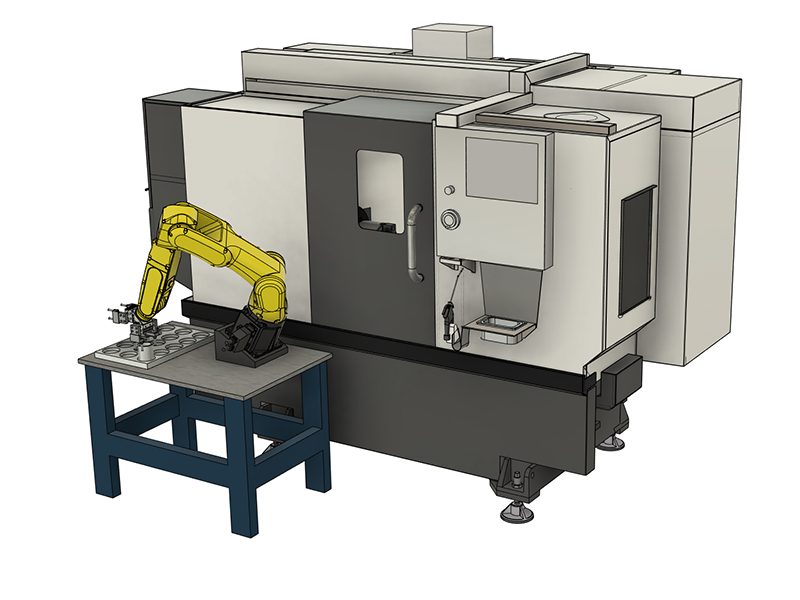
Sistemas de automatización
Sistemas de automatización
-
Máquinas de sobremesa
Máquinas de sobremesa
-
Equipo de taller
Equipo de taller
-
Máquinas de fabricación
Máquinas de fabricación
COMPRAR HERRAMIENTAS¿QUIERE HABLAR CON ALGUIEN?En las tiendas Haas Factory Outlet (HFO) pueden resolver sus dudas y orientarlo sobre las mejores opciones.
CONTACT YOUR DISTRIBUTOR > -
Fresadoras verticales
-
Opciones
-
/2026-04-VOP-SquareComponent.jpg/_jcr_content/renditions/cq5dam.thumbnail.319.319.png) Los paquetes Value Option
Los paquetes Value Option
Los paquetes Value Option
Los paquetes Value Option -
 Husillos
Husillos
Husillos -
 Cambiadores de herramientas
Cambiadores de herramientas
Cambiadores de herramientas -
 4.º | 5.º eje
4.º | 5.º eje
4.º | 5.º eje -
 Torretas y herramientas motorizadas
Torretas y herramientas motorizadas
Torretas y herramientas motorizadas -
 Palpado
Palpado
Palpado -
 Tratamiento de refrigerante y virutas
Tratamiento de refrigerante y virutas
Tratamiento de refrigerante y virutas -
 El Control Haas
El Control Haas
El Control Haas -
 Opciones para productos
Opciones para productos
Opciones para productos -
 Herramientas y utillaje
Herramientas y utillaje
Herramientas y utillaje -
 Portapiezas
Portapiezas
Portapiezas -
 Soluciones de 5 ejes
Soluciones de 5 ejes
Soluciones de 5 ejes -
 Automatización
Automatización
Automatización
COMPRAR HERRAMIENTAS¿QUIERE HABLAR CON ALGUIEN?En las tiendas Haas Factory Outlet (HFO) pueden resolver sus dudas y orientarlo sobre las mejores opciones.
CONTACT YOUR DISTRIBUTOR > -
-
Why Haas
Descubra la diferencia Haas
-
Servicio técnico
- Vídeos
- Herramientas de Haas


-setup/Machines-Top-View.png)
-setup/FANUC%20DCS%20Safe%20Zone%20Setup%20J2%20Measuring%201.jpg)
-setup/step-2.png)
-setup/Table.jpg)
-setup/step-4.png)
-setup/step-5.png)
-setup/step-6.png)
-setup/step-7.png)
-setup/step-8.png)
-setup/DCS-User-Frame-Setup-1.png)
-setup/DCS-User-Frame-30-degree-Y-axis.png)
-setup/DCS-User-Frame-35-degree-Z-axis.png)
-setup/DCS-User-Frame-Setup-2-2.png)
-setup/DCS-Cartesian-Position-Check-Setup-1.png)
-setup/DCS-Cartesian-Position-Check-Setup-2.png)
-setup/DCS-Cartesian-Position-Check-Setup-3-2.png)
-setup/DCS-Cartesian-Position-Visualization-1.png)
-setup/HMI%20iPendant%2034.jpg)
-setup/Verify-DCS-Zone-Jogging.png)