×

Rezultatele căutării

Web Pages

Images

    • <
    • 1
    • >
  • mașini
    • Frezele verticale Haas
      Freze verticale
      • Freze verticale
      • Seriile VF
      • Mașinile universale
      • Seria VR
      • VMC-uri cu schimbarea paletelor
      • Mini Mills
      • Mașini de prelucrare matrițe
      • Seriile pentru găurire/tarodare/frezare
      • Freze pentru sculărie
      • Freze compacte
      • Seriile portal
      • Frezare/strunjire verticală
      • VMC foarte mare
      • Freze cu coloană dublă
      • Freze desktop
      • Încărcătorul automat de piese al frezei
    • Product Image
      Soluții în mai multe axe
      • Soluții în mai multe axe
      • Freze pe 5 axe
      • Strunguri pe axa Y
    • Strunguri Haas
      Strunguri
      • Strunguri
      • Seria ST
      • Arbore dublu
      • Strunguri de sculărie
      • Strung cu mandrină
      • Alimentator de bare Haas V2
      • Încărcător de piese automat pentru strung
    • Frezele orizontale Haas
      Freze orizontale
      • Freze orizontale
      • Con 50
      • Con 40
    • Mese rotative și indexoare Haas
      Mese rotative și indexoare
      • Mese rotative și indexoare
      • Mese rotative
      • Indexoare
      • Unități rotative în 5 axe
      • Unități rotative foarte mari
    • Product Image
      Sisteme de automatizare
      • Sisteme de automatizare
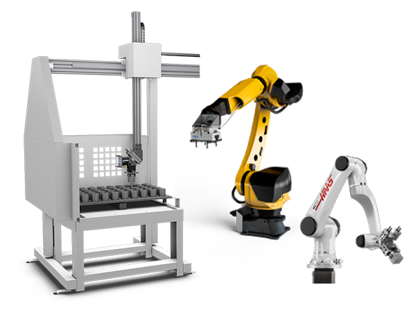
      • Sistem de roboți
      • Încărcătoare automate de piese
      • Sistemele pentru fondul de palete
      • Alimentator de bare Haas
      • Models
    • LINK-URI RAPIDE Serie specială  Serie specială 
      CARIERE LA HAAS CARIERE LA HAAS CONFIGURARE ȘI PREȚ CONFIGURARE ȘI PREȚ LISTĂ DE PREȚURI LISTĂ DE PREȚURI CE ESTE NOU CE ESTE NOU PRIMA DVS. MAȘINĂ CNC PRIMA DVS. MAȘINĂ CNC HAAS SIX PACK HAAS SIX PACK
      CUMPĂRAREA SCULELOR
      • Configurare și preț mașină Haas
      • Listă de prețuri
      • Inventar disponibil
      • Finanțare CNCA
      AVEȚI NEVOIE DE CONSILIERE?

      O reprezentanță Haas (HFO) vă poate răspunde la întrebări și vă poate ghida spre cele mai bune opțiuni.

      CONTACT YOUR DISTRIBUTOR >
  • Opțiuni
    • Product Image
      Arbori principali
      • Arbori principali
    • Product Image
      Schimbătoare de scule
      • Schimbătoare de scule
    • Product Image
      Axa a 4-a | 5-a
      • Axa a 4-a | 5-a
    • Product Image
      Capete revolver și ansamblul sculelor antrenate
      • Capete revolver și ansamblul sculelor antrenate
    • Product Image
      Palpare
      • Palpare
    • Gestionarea Haas a șpanului și a lichidului de răcire
      Gestionarea șpanului și a lichidului de răcire
      • Gestionarea șpanului și a lichidului de răcire
    • Unitatea de comandă Haas
      Unitatea de comandă Haas
      • Unitatea de comandă Haas
    • Product Image
      Opțiunile produsului
      • Opțiunile produsului
    • Product Image
      Scule și dispozitive de fixare
      • Scule și dispozitive de fixare
    • Product Image
      Sistemul de suport piesă
      • Sistemul de suport piesă
    • Product Image
      Soluții în 5 axe
      • Soluții în 5 axe
      • 5 Easy Steps to 5-Axis
    • Product Image
      Automatizare
      • Automatizare
    • LINK-URI RAPIDE Serie specială  Serie specială 
      CARIERE LA HAAS CARIERE LA HAAS CONFIGURARE ȘI PREȚ CONFIGURARE ȘI PREȚ LISTĂ DE PREȚURI LISTĂ DE PREȚURI CE ESTE NOU CE ESTE NOU PRIMA DVS. MAȘINĂ CNC PRIMA DVS. MAȘINĂ CNC HAAS SIX PACK HAAS SIX PACK
      CUMPĂRAREA SCULELOR
      • Configurare și preț mașină Haas
      • Listă de prețuri
      • Inventar disponibil
      • Finanțare CNCA
      AVEȚI NEVOIE DE CONSILIERE?

      O reprezentanță Haas (HFO) vă poate răspunde la întrebări și vă poate ghida spre cele mai bune opțiuni.

      CONTACT YOUR DISTRIBUTOR >
  • Why Haas
      Descoperiți diferența Haas
      De ce Haas MyHaas Comunitate pentru învățare Industry 4.0 Certificare Haas Mărturiile clienților
  • Service
      Bine ați venit la departamentul de service Haas
      PAGINA PRINCIPALĂ SERVICE Manualele de utilizare Instrucțiuni de folosire Ghiduri de depanare Întreținerea preventivă a mașinii Piese Haas Prelucrare Haas Videoclipuri
  • Videoclipuri
  • MyHaas - Un loc pentru toate

    • Compare Quotes
      • Compare Quotes

    • Despre MyHaas
      • Despre MyHaas

    • Programul de certificare CNC oferit de Haas
      • Programul de certificare CNC oferit de Haas

    • Haas CNC Certification Program-Redirect
      • Haas CNC Certification Program-Redirect

    • Programul de certificare CNC oferit de Haas
      • Programul de certificare CNC oferit de Haas

    • Haas Learning Resources
      • Haas Learning Resources

    • Haas Global Learning Resources
      • Haas Global Learning Resources

    • MyHaas App Form
      • MyHaas App Form
    • LINK-URI RAPIDE Serie specială  Serie specială 
      CARIERE LA HAAS CARIERE LA HAAS CONFIGURARE ȘI PREȚ CONFIGURARE ȘI PREȚ LISTĂ DE PREȚURI LISTĂ DE PREȚURI CE ESTE NOU CE ESTE NOU PRIMA DVS. MAȘINĂ CNC PRIMA DVS. MAȘINĂ CNC HAAS SIX PACK HAAS SIX PACK
      CUMPĂRAREA SCULELOR
      • Configurare și preț mașină Haas
      • Listă de prețuri
      • Inventar disponibil
      • Finanțare CNCA
      AVEȚI NEVOIE DE CONSILIERE?

      O reprezentanță Haas (HFO) vă poate răspunde la întrebări și vă poate ghida spre cele mai bune opțiuni.

      CONTACT YOUR DISTRIBUTOR >

    • HFO Romania
      • HFO Romania
      • Despre
      • Service
      • Training
      • Finanțare
      • Evenimente
      • Mașini de Showroom
      • Contactați-ne
      • Customer Testimonials
    • LINK-URI RAPIDE Serie specială  Serie specială 
      CARIERE LA HAAS CARIERE LA HAAS CONFIGURARE ȘI PREȚ CONFIGURARE ȘI PREȚ LISTĂ DE PREȚURI LISTĂ DE PREȚURI CE ESTE NOU CE ESTE NOU PRIMA DVS. MAȘINĂ CNC PRIMA DVS. MAȘINĂ CNC HAAS SIX PACK HAAS SIX PACK
      CUMPĂRAREA SCULELOR
      • Configurare și preț mașină Haas
      • Listă de prețuri
      • Inventar disponibil
      • Finanțare CNCA
      AVEȚI NEVOIE DE CONSILIERE?

      O reprezentanță Haas (HFO) vă poate răspunde la întrebări și vă poate ghida spre cele mai bune opțiuni.

      CONTACT YOUR DISTRIBUTOR >
  • Contactați-ne

My Cart
MyHaas Bun venit,
!
Haas Tooling Istoricul comenzilor invitatului MyHaas/HaasConnect Înregistrare Înregistrare Haas Tooling Contul meu Order History Return History MyHaas/HaasConnect Deconectare Bun venit, Mașinile mele Cea mai recentă activitate Cotațiile mele Contul meu Utilizatorii mei Deconectare
Găsiți un reprezentant de vânzări
  1. Selectare limbă
    1. English
    2. Deutsch
    3. Español
    4. Français
    5. Italiano
    6. Português
    7. Český
    8. Dansk
    9. Nederlands
    10. Magyar
    11. Polski
    12. Svenska
    13. Русский
    14. Türkçe
    15. 中文
    16. Suomi
    17. Norsk
    18. الإنجليزية
    19. български
    20. Hrvatski
    21. Ελληνικά
    22. Română
    23. Slovenský
    24. Slovenščina
    25. 한국어
    26. 日本語
Search
×

Rezultatele căutării

Web Pages

Images

    • <
    • 1
    • >

FANUC Dual Check Safety Setup

Pachet de roboți Haas - Manual de utilizare/service


  • 1 – HRP – Prezentare
  • Mill Installation
  • Lathe Installation
  • 2 – HRP – Informații juridice
  • 3 – HRP – Siguranță
  • 4 – HRP-1 – Instalare
  • 5 – HRP-2 – Instalare
  • 6 – HRP-3 – Instalare
  • 7 – HRP – Instalare parapet
  • 8 – HRP – Configurare DCS FANUC
  • 9 – HRP – Funcționare
  • 10 – HRP – Întreținere
  • 11 – HRP – Depanare

Go To :

  • 8.1 Dual Check Safety
Recently Updated

Haas Robot – FANUC Dual Check Safety (DCS) – Setup


Introduction

Each Haas Robot is provided with FANUC's DCS System. This allows the user to define speed and positional limits to the robot. If the robot goes outside of these limits, DCS will stop the robot and remove power to the motors.

This guide will show how to configure a simple Cartesian Positon Check limits for your robot. The Cartesian Position Check Function allows a user to define a work zone and a restricted zone for the robot. If the robot exits a defined work zone then DCS will stop the robot. If any part of the robot violates a restricted zone, then DCS will stop the robot. The user must jog the robot back to it's work zone, or out of the restricted zone at a reduced speed or the robot will alarm out.

The Robot Package comes pre-configured with Cartesian Speed Check limits for RUN and SETUP mode.

Note: Verify proper setup of the DCS zones at the time of robot installation and every 6 months. It should also be verified after a new job has been set up.

These instructions require that your robot be aligned with your fence. 

Note: If the robot was not aligned with the fence, the work zone will be smaller than expected.

Measuring Safe Zone Size

1

The work zone size will be referenced and measured from the center of J2 axis of the robot. One surface and one edge from J2 we will measure from in order to get the center of J2. If using the flat from surface A, we will add 4.5in or 114mm to our measurements. If using surface B, we will add 2.5in or 63.5mm to our measurements.

Turn on machine and robot, make sure both are connected to each other. Jog the J1 robot axis so that it is at 90, 0 or -90 degrees. Your robot surfaces A and B should now be parallel to the fence and machine door.

2

Cut out the XY coordinate system and place it on your robot table to help visualize where we are taking measurements in relation to the coordinate system.

The coordinate system for your application will depend on how your robot is positioned on the table. The side of the robot base with power cables coming out is the X- direction. The battery cover on the base of the robot is the Y+ direction.

Note: This coordinate system is considered to be the world frame. World frame in this application is rotated along X by -30 degrees because of the way the robot base is mounted on the tilt mount. Later in the steps we will be assigning a user frame for this safe zone that will have a simple 30 degree X rotation which will cancel out the physical tilt of the base.

Align the coordinate system reference with the XY direction of your robot setup.

3

Use the table provided to fill in your measurements.

Note: All dimensions will need to be converted to millimeters.

Make sure to measure the distances with the measuring tape parallel to the axis on the coordinate system print out.

Note: There will be one positive and one negative value for X, Y and Z.

*The Z distances can be adjusted for more clearance above and below the robot. This value is measured from the center of J2.

4

Warning: The following dimensions are an example and should not be used for DCS Setup.

Measure the distance from the center of J2 to the fence on opposite of the machine. This is the positive X-direction when referencing the coordinate system print out.

Example: The distance of the positive X-direction for point 1 is 24.5” this is calculated as:

  • The edge of J2 to the center of J2 = +4.5”
  • The edge of J2 to the fence = +20.0”

Enter the total distance into the table corresponding to the direction of measurement. The X-axis in the positive direction was measured. The value is entered into the table in the X row and Point 1 column. The dimension will have a positive value.

5

Measure the distance from the center of J2 axis to the fence. This is the negative Y-direction when referencing the coordinate system print out.

Example: The distance of the negative Y-direction for point 1 is -34.5”, this is calculated as:

  • The edge of J2 to the center of J2 = -2.5”
  • The edge of J2 to the fence = -32.0”

Enter the total distance into the table corresponding to the direction of measurement. The Y-axis in the negative direction was measured. The value is entered into the table in the Y row and Point 1 column. The dimension will have a negative value.

6

Measure the distance from the center of J2 to the inside of the machine past the workholding. This is the negative X-direction when referencing the coordinate system print out.

Example: The distance of the negative X-direction for point 2 is -39.5” this is calculated as:

  • The edge of J2 to the center of J2 = -4.5”
  • The edge of J2 to the face of the closed door = -11.0”
  • The face of the open door to past the workholding = -24.0"

Enter the total distance into the table corresponding to the direction of measurement. The X-axis in the negative direction was measured. The value is entered into the table in the X row and Point 2 column. The dimension will have a negative value.

Note: If this safe zone measurement is incorrectly calculated. The safe zone may be placed too close to work holding. This value can be adjusted to add more work space inside the machine.

7

Measure the distance from the center of J2 axis to the edge of the door opening. This is the positive Y-direction when referencing the coordinate system print out.

Example: The distance of the positive Y-direction for point 2 is 28.5”, this is calculated as:

  • The edge of J2 to the center of J2 = 2.5”
  • The edge of J2 to the edge of the door opening = 26.0”

Enter the total distance into the table corresponding to the direction of measurement. In the case above, the Y+ axis was measured, so the value would go into point 2 with a positive value.

8

The Z value for each point is in the table. If more ceiling work envelope is needed, the positive Z distance can be increased. If more floor work envelope is needed, the negative Z distance can be increased.

After taking measurements, double check values. The values are creating a box around the robot that is referenced from the center of J2.

DCS User Frame Setup

1

To setup a DCS User Frame, a computer with internet access will need to be connected to the Robot Control Box with a RJ-45 cable. Open the front door of your robot controller and unplug the RJ-45 cable from Port 1 [1]. Plug in a new RJ-45 cable that is connected to a computer that has internet access. Follow the video above to setup the adapter settings on your computer to match the robot IP address.

Note: When finished setting up the DCS User frame, disconnect the RJ-45 cable from the computer and robot and plug the RJ-45 back into the Port 1.

2

Login to the HMI Jogging Pendant from your web browser.

Navigate to the User Frame Setup view.

Click on Frame 9 then click DETAIL.


3

For Robot Package 1 Only

Select W and enter the value of 30.0 then hit enter on your keyboard.

This is where we are adding a 30 degree X rotation to the world frame to cancel out the tilt of the robot base.

4

Navigate to DCS Menu.

Enable the pendant by hitting the ON/OFF button on the top right.

Enter user frame section (10).

Select the second zero in the list under No. column and press 9. Confirmation question will show at the bottom, press YES. Change that value to 9 after confirmation.

You should see W populate with the same value from step 2.

Go back to DCS menu.

DCS Cartesian Position Check Setup

1

Go into Cart. Position Check (5).

Go into No. 1.

Enable the position check No. 1 by selecting then pressing [CHOICE] at the bottom.

Change the Method type to Work Zone (Diagonal) by clicking the row then selecting [CHOICE] at the bottom.

Target Model 1 should say Robot Model, Target model 2 and 3 should be disabled.

Set Base Frame: User Frame: to 9 by selecting then entering 9.

2

In Point 1 and 2, enter in the values that were recorded from earlier in the guide. This is where we define the two points for the work space diagonal box.

For Stop Type, click the row then select [CHOICE] at the bottom and change to Speed Check(1).

Make sure Stop Prediction is Yes.

Click on <DETAIL> under Speed Check then hit ENTER on your keyboard.

Set Limit 1 to 20.0, Delay Time to 0, and Permissable distance to 0.0, Speed Control to DISABLE.

Press PREV 3 times to get back to the Main DCS screen.

3

Now we will apply the all the changes we made in the DCS menu. Any DCS section that was changed since last APPLY will show a RED CHGD next to it. Press APPLY at the bottom.

Enter 1111 for the Master Code.

This will take you to another menu that will show you the changes made in the DCS menu since last apply. Press OK if all changes are correct.

Close the HMI Pendant Window.

Cycle power on the robot controller by turning the power switch OFF, waiting 5 seconds then back ON.

Setup is complete. There is now a work zone setup around the robot. If any part of the robot leaves the work zone at a speed greater than 20mm/s, it will alarm. If this alarm is triggered, it is possible to reset the alarm and jog back into the zone at a rate less than 20mm/s. The next section covers how to visualize the zone that was just created.

DCS Cartesian Position Visualization

1

With the Work Zone setup, we want a way to visualize the zone in relation to the robot.

Access the Jogging HMI Pendant and navigate to MENU > NEXT > 4D Graphics.

You will see the robot virtually on the HMI pendant along with its current orientation.

To see the DCS zone, click on [VISIBLE] at the bottom bar, if it is not there, press the > arrow on the bar.

2

A new menu will display in the top left of the 4D display. Click on 4D DCS Display, it will turn a shade of blue to signify that it is ON. You will see a box appear if your DCS zone is enabled and setup.

Verify that the work zone that appears is surrounding your robot. If the zone is a shade of red, that means a part of the robot is outside of the zone. If the zone is green that means your robot is within the zone.

This display will update in real time, you can have this open on your laptop/computer while you jog the robot with the HAAS machine.

This zone can be modified with the Point 1 and Point 2 XYZ positions from step. It is OK if the zone is angled in the 4D display, because the robot base is angled in real world (in our application).

DCS Cartesian Position Verification

1

Note: When finished setting up the DCS User frame, disconnect the RJ-45 cable from the computer and robot and plug the RJ-45 back into the Port 1.

Verify the DCS zone by jogging the robot in the positive Y-direction to a safe location out of the DCS zone and check if the machine alarms.

If it does, jog back into the DCS zone.

Note: To jog back into the DCS zone without alarming the machine, lower the jogging feedrate.

Feedback
GĂSIȚI UN DISTRIBUITOR
Feedback
Haas Logo

美元价格不包括关税、报关费用、保险费、增值税及运费。
USD prices DO NOT include customs duty, customs fees, insurance, VAT, or freight.

人民币价格包含关税、报关费用、货运保险和增值税, 但不包括运费。
CNY prices include customs duty, customs fees, insurance, and VAT. DOES NOT include freight.

Preț de livrare Haas

Prețul include costul transportului, taxele de export și import, asigurarea și orice alte cheltuieli apărute în timpul expedierii către o locație din Franța, stabilită de comun acord cu dvs. în calitate de cumpărător. Nu pot fi adăugate alte costuri obligatorii la livrarea unui produs CNC de la Haas.

RĂMÂNEȚI LA CURENT CU CELE MAI RECENTE SFATURI ȘI TEHNOLOGII HAAS...

Înregistrați-vă acum!   

HAAS TOOLING ACCEPTS THE FOLLOWING:

  • Servicii și asistență
  • Proprietari
  • Solicitare de service
  • Manuale de utilizare
  • Piese Haas
  • Solicitare de reparație masă rotativă
  • Ghiduri de pre-instalare
  • Cumpărarea sculelor
  • Configurare și preț pentru o mașină Haas nouă
  • Inventar disponibil
  • Listă de prețuri Haas
  • Finanțare CNCA
  • Despre Haas
  • Cariere
  • Certificări și siguranță
  • Contactați-ne
  • Istoric
  • Termeni și condiții
  • Termene și condiții Haas Tooling
  • Confidențialitate
  • Garanție
  • Comunitatea Haas
  • Programul de certificare oferit de Haas
  • Sporturi cu motor Haas
  • Fundația Gene Haas
  • Comunitatea pentru formare tehnică Haas
  • Evenimente
  • Alăturați-vă conversației
  • Facebook
  • Twitter
  • Flickr
  • YouTube
  • LinkedIn
  • Instagram
  • TikTok
© 2022 Haas Automation, Inc – Mașini-unelte CNC

2800 Sturgis Rd., Oxnard, CA 93030 / Toll Free: 800-331-6746
Phone: 805-278-1800 / Fax: 805-278-2255

Politica privind cookie-urile

Utilizăm cookie-uri pentru a îmbunătăți experiența utilizatorilor. Politica noastră privind cookie-urile descrie ce cookie-uri utilizăm, de ce le utilizăm și modul în care puteți afla mai multe informații despre acestea. Confirmați că sunteți de acord să utilizăm cookie-uri Analytics. Dacă nu sunteți de acord, puteți utiliza în continuare site-ul nostru fără a beneficia de o experiență îmbunătățită pentru utilizator.

Administrează setările

Politica privind cookie-urile

Utilizăm cookie-uri pentru a îmbunătăți experiența utilizatorilor. Politica noastră privind cookie-urile descrie ce cookie-uri utilizăm, de ce le utilizăm și modul în care puteți afla mai multe informații despre acestea. Confirmați că sunteți de acord să utilizăm cookie-uri Analytics. Dacă nu sunteți de acord, puteți utiliza în continuare site-ul nostru fără a beneficia de o experiență îmbunătățită pentru utilizator.

Functional Cookies

Analytics Cookies