MyHaas Hoş Geldiniz,
!
Haas Tooling MyHaas/HaasConnect Oturum Aç Kaydol Haas Tooling MyHaas/HaasConnect Oturumu Kapat Hoş Geldiniz, Makinelerim Son Etkinlik Fiyat Tekliflerim Hesabım Kullanıcılarım Oturumu Kapat
Distribütörünüzü Bulun
  1. Dil Seçenekleri
    1. English
    2. Deutsch
    3. Español - ES
    4. Español - MX
    5. Français
    6. Italiano
    7. Português
    8. Český
    9. Dansk
    10. Nederlands
    11. Magyar
    12. Polski
    13. Svenska
    14. Türkçe
    15. 中文
    16. Suomi
    17. Norsk
    18. الإنجليزية
    19. български
    20. Hrvatski
    21. Ελληνικά
    22. Română
    23. Slovenský
    24. Slovenščina
    25. 한국어
    26. 日本語
    27. Українська
  • tezgahlar Main Menu
    • Dik Frezeler
      Dik Frezeler
      Dik Frezeler View All
      • Dik Frezeler
      • VF Serisi
      • Üniversal Makineler
      • VR Serisi
      • VP-5 Prizmatik
      • Palet Değiştiricili VMC’ler
      • Mini Frezeler
      • Kalıp Makineleri
      • Yüksek Hızlı Delme Merkezleri
      • Delme/Kılavuz Çekme/Freze Serisi
      • Takımhane Frezesi
      • Pocket Mill
      • Kompakt Frezeler
      • Gantry Serisi
      • SR Tabaka Yönlendiricileri
      • Ekstra Büyük VMC
      • Çift Kolonlu Frezeler
      • 3+2 Konumlandırma Makineleri
    • Çok Eksenli Çözümler
      Çok Eksenli Çözümler
      Çok Eksenli Çözümler View All
      • Çok Eksenli Çözümler
      • Y Eksenli Tornalar
      • 5-Eksenli Frezeler
    • Tornalar
      Tornalar
      Tornalar View All
      • Tornalar
      • ST Serisi
      • Çift İş Mili
      • Kutu Kızak Serisi
      • Takımhane Tornası
      • Aynalı Torna
      • Cep Tornası
      • Haas Çubuk Sürücüler
    • Yatay Frezeler
      Yatay Frezeler
      Yatay Frezeler View All
      • Yatay Frezeler
      • 50 Konikli
      • 40 Konikli
    • Döner ve İndeksleyici
      Döner ve İndeksleyici
      Döner ve İndeksleyici View All
      • Döner ve İndeksleyici
      • Döner Tablalar
      • İndeksleyiciler
      • 5 Eksen Döner Tablalar
      • Çok Büyük Döner Tablalar
    • Otomasyon Sistemleri
      Otomasyon Sistemleri
      Otomasyon Sistemleri View All
      • Otomasyon Sistemleri
      • Freze Otomasyonu
      • Torna Otomasyonu
      • Otomatik Parça Yükleyiciler
      • Otomasyon Modelleri
    • Masaüstü Makineler
      Masaüstü Makineler
      Masaüstü Makineler View All
      • Masaüstü Makineler
      • Masaüstü Freze
      • Masaüstü Torna
      • Kontrol Simülatörü, Standart
      • Kontrol Simülatörü, Premium
    • Atölye Ekipmanı
      Atölye Ekipmanı
      Atölye Ekipmanı View All
      • Atölye Ekipmanı
      • Mafsallı Freze
      • Haas Manuel Tornalar
      • Haas Testereler
    • İmalat Makineleri
      İmalat Makineleri
      İmalat Makineleri View All
      • İmalat Makineleri
      • Lazer Kesme Makineleri
      • CNC Pres Frenleri
    • HIZLI BAĞLANTILAR Özel Seri  Özel Seri 
      AB SERİSİ AB SERİSİ OLUŞTURMA VE FİYATLANDIRMA | FİYAT LİSTESİ OLUŞTURMA VE FİYATLANDIRMA | FİYAT LİSTESİ Stoktaki Makineler Stoktaki Makineler YENİLİKLER YENİLİKLER İLK CNC’NİZ İLK CNC’NİZ
      ALIŞVERİŞ ARAÇLARI
      • Bir Haas Oluştur ve Fiyatlandır
      • Fiyat Listesi
      • Mevcut Stok
      • CNCA Taksit Seçenekleri
      BİR YETKİLİYLE Mİ GÖRÜŞMEK İSTİYORSUNUZ?

      Bir Haas Fabrika Satış Mağazası (HFO) sorularınızı cevaplayabilir ve en iyi seçenekler konusunda size yardımcı olabilir.

      CONTACT YOUR DISTRIBUTOR >
  • Seçenekler Main Menu
    • The Haas Control Değer Seçenek Paketleri
      Değer Seçenek Paketleri
      Değer Seçenek Paketleri View All
      • Değer Seçenek Paketleri
    • Product Image İş Milleri
      İş Milleri
      İş Milleri View All
      • İş Milleri
    • Product Image Takım Değiştiriciler
      Takım Değiştiriciler
      Takım Değiştiriciler View All
      • Takım Değiştiriciler
    • Product Image 4. | 5. Eksen
      4. | 5. Eksen
      4. | 5. Eksen View All
      • 4. | 5. Eksen
    • Product Image Taretleri ve Tahrik Takımı
      Taretleri ve Tahrik Takımı
      Taretleri ve Tahrik Takımı View All
      • Taretleri ve Tahrik Takımı
    • Product Image Problama
      Problama
      Problama View All
      • Problama
    • Haas Talaş ve Soğutma Sıvısı Yönetimi Talaş ve Soğutma Sıvısı Yönetimi
      Talaş ve Soğutma Sıvısı Yönetimi
      Talaş ve Soğutma Sıvısı Yönetimi View All
      • Talaş ve Soğutma Sıvısı Yönetimi
    • Haas Kontrol Ünitesi Haas Kontrol Ünitesi
      Haas Kontrol Ünitesi
      Haas Kontrol Ünitesi View All
      • Haas Kontrol Ünitesi
    • Product Image Ürün Seçenekleri
      Ürün Seçenekleri
      Ürün Seçenekleri View All
      • Ürün Seçenekleri
    • Product Image Takımlar ve Fikstürleme
      Takımlar ve Fikstürleme
      Takımlar ve Fikstürleme View All
      • Takımlar ve Fikstürleme
    • Product Image İş Parçası Bağlama
      İş Parçası Bağlama
      İş Parçası Bağlama View All
      • İş Parçası Bağlama
    • Product Image 5 Eksen Çözümler
      5 Eksen Çözümler
      5 Eksen Çözümler View All
      • 5 Eksen Çözümler
      • 5 Easy Steps to 5-Axis
    • Product Image Otomasyon
      Otomasyon
      Otomasyon View All
      • Otomasyon
    • HIZLI BAĞLANTILAR Özel Seri  Özel Seri 
      AB SERİSİ AB SERİSİ OLUŞTURMA VE FİYATLANDIRMA | FİYAT LİSTESİ OLUŞTURMA VE FİYATLANDIRMA | FİYAT LİSTESİ Stoktaki Makineler Stoktaki Makineler YENİLİKLER YENİLİKLER İLK CNC’NİZ İLK CNC’NİZ
      ALIŞVERİŞ ARAÇLARI
      • Bir Haas Oluştur ve Fiyatlandır
      • Fiyat Listesi
      • Mevcut Stok
      • CNCA Taksit Seçenekleri
      BİR YETKİLİYLE Mİ GÖRÜŞMEK İSTİYORSUNUZ?

      Bir Haas Fabrika Satış Mağazası (HFO) sorularınızı cevaplayabilir ve en iyi seçenekler konusunda size yardımcı olabilir.

      CONTACT YOUR DISTRIBUTOR >
  • Why Haas Main Menu
      Haas Farkını Keşfedin
    • Neden Haas
    • MyHaas
    • Eğitim Topluluğu
    • Endüstri 4.0
    • Haas Sertifikası
    • Müşteri Görüşleri
  • Servis Main Menu
      Haas Service Hoş Geldiniz
      SERVİS ANA SAYFA Operatör El Kitapları Nasıl Yapılır Prosedürleri Sorun Giderme Kılavuzları Önleyici Bakım Haas Parçaları Haas Tooling Videolar
  • Videolar Main Menu
  • Main Menu
    • View All
      • Financing
    • View All
      • Showroom Inventory
    • HIZLI BAĞLANTILAR Özel Seri  Özel Seri 
      AB SERİSİ AB SERİSİ OLUŞTURMA VE FİYATLANDIRMA | FİYAT LİSTESİ OLUŞTURMA VE FİYATLANDIRMA | FİYAT LİSTESİ Stoktaki Makineler Stoktaki Makineler YENİLİKLER YENİLİKLER İLK CNC’NİZ İLK CNC’NİZ
      ALIŞVERİŞ ARAÇLARI
      • Bir Haas Oluştur ve Fiyatlandır
      • Fiyat Listesi
      • Mevcut Stok
      • CNCA Taksit Seçenekleri
      BİR YETKİLİYLE Mİ GÖRÜŞMEK İSTİYORSUNUZ?

      Bir Haas Fabrika Satış Mağazası (HFO) sorularınızı cevaplayabilir ve en iyi seçenekler konusunda size yardımcı olabilir.

      CONTACT YOUR DISTRIBUTOR >
MyHaas Hoş Geldiniz,
!
Haas Tooling MyHaas/HaasConnect Oturum Aç Kaydol Haas Tooling MyHaas/HaasConnect Oturumu Kapat Hoş Geldiniz, Makinelerim Son Etkinlik Fiyat Tekliflerim Hesabım Kullanıcılarım Oturumu Kapat
Distribütörünüzü Bulun
  1. Dil Seçenekleri
    1. English
    2. Deutsch
    3. Español - ES
    4. Español - MX
    5. Français
    6. Italiano
    7. Português
    8. Český
    9. Dansk
    10. Nederlands
    11. Magyar
    12. Polski
    13. Svenska
    14. Türkçe
    15. 中文
    16. Suomi
    17. Norsk
    18. الإنجليزية
    19. български
    20. Hrvatski
    21. Ελληνικά
    22. Română
    23. Slovenský
    24. Slovenščina
    25. 한국어
    26. 日本語
    27. Українська
×

Arama Sonuçları

Web Pages

Images

    • <
    • 1
    • >

5 - HC10 - Installation

Haas Cobot Package - Operator's/Service Manual


  • 0 - Haas Cobot - İçindekiler
  • 1 - Haas Cobot - Introduction
  • 2 - Haas Cobot - Legal Information
  • 3 - Haas Cobot - Safety
  • 4 - HC5 - Installation
  • 5 - HC10 - Installation
  • 6 - HC15 - Installation
  • 7 - HC30 - Installation
  • 8 - Haas Cobot - Fence/Interlock Installation
  • 9 - Haas Cobot - Area Scanner Installation
  • 10 - Haas Cobot - Light Curtain Installation
  • 11 - Haas Cobot - Operation
  • 12 - Haas Cobot - Maintenance
  • 13 - Haas Cobot - Troubleshooting

Go To :

  • 5.1 VMC Kurulumu
  • 5.2 Torna Kurulum
  • 5.3 DM/DT/MM/DC-1/UMC-350 Kurulumu
  • 5.4 UMC-400/500 Kurulumu

5.1 VMC Kurulumu

Recently Updated

Haas Cobot 10 (HC10) - VMC - Kurulum


AD0714

Revizyon C - 09/2025

Giriş

Bu prosedür size Haas 10KG Cobot (HC10) nasıl kuruluru gösterecektir.

 Not: Haas’ın CNC makinesi ve robottan oluşan tasarımlı çalışma hücresi, CE gerekliliklerine uygunluk açısından değerlendirilmiştir. Haas hücre tasarımındaki değişiklikler veya varyasyonlar, geçerli standartlara uygunluk açısından değerlendirilmelidir ve kullanıcının/entegre edenin sorumluluğundadır.

Updated

Makine gereksinimleri:

  • 100.24.000.1001 sürümü veya üzeri
  • HR5.51H.16.beta.20231213.zip sürümü veya HR6.4.9.tmp20240919.zip sürümü
  • VF-1/2 ve VM-2 Üretime Girme Tarihi: (her iki prosedürde de makine gerekliliklerine bakın)
  • DC-2
  • Haas Otomatik Kapı 
  • Haas Otomatik Pencere
  • 34-349xB I/O kartı veya üzeri
  • 93-1000610 UZAKTAN EL KUMANDASI DOKUN LCD (RJH-XL) UZAKTAN EL KUMANDASI - XL
  • Takım Gereksinimleri:

    • Mini Düz Kafa Tornavida

    Sabitleme/Sabitleme Gereklilikleri

    • Haas 10 KG Cobot (HC10), Haas tarafından tanımlanan parça boyutu ve ağırlık sınırlarına göre kullanıldığında yeterince sabit olan bir kaide/tabla ile yapılandırılır ve satılır. 
    ÖNEMLİ:  Doğrudan Hans Cobot hakkında daha fazla bilgi için bkz. Elfin Yazılımı için Hans Robot Çalıştırma Kılavuzu.

    Cobot seçeneğinin bir Haas makinesine kurulabileceği 3 senaryo vardır:

    1. Cobot opsiyonu makine ile aynı anda sipariş edilmiştir. Hem cobot hem de makine birlikte kurulmaktadır.
    2. Cobot opsiyonu, daha önce kurulmuş bir makineye kurulabilmesi için sipariş edilmektedir.
    3. Cobot opsiyonu daha önce bir makineye kurulmuş, ancak şimdi farklı bir Haas makinesine taşınmaktadır.

    2. ve 3. senaryolarda Haas makinesinin Seri Numarası altında ek parçaların sipariş edilmesi gerekecektir. Farklı senaryolarda hangi parçaların gerekli olduğunu görmek için aşağıdaki tablolara bakın.

    Senaryo 1 - Cobot ve makine sipariş edilip birlikte kurulmaktadır

    Eleman: Parça Numarası Açıklama
    COBOT VE MAKİNE BİRLİKTE SİPARİŞ EDİLDİĞİNDE EK PARÇA SİPARİŞİ VERİLMEZ

    Senaryo 2 - Cobot mevcut Haas Makineye sahada monte edilmektedir

    Eleman: Parça Numarası Açıklama
    SİPARİŞ VERMEDEN ÖNCE HAAS MAKİNESİNİN BU ÖZELLİK VE PARAMETRELERE SAHİP OLUP OLMADIĞINI KONTROL EDİN
    Robot Özelliği Kilit Açma Parametresi 93-1001031 Kit, Haas makinesinde robot özelliğini aktif hale getirir. Bu kite ihtiyacınız olup olmadığını kontrol etmek için Haas Control'deki Özellikler sekmesine gidin ve Robot seçeneğinin vurgulanıp vurgulanmadığını kontrol edin. Bu kitte herhangi bir fiziksel parça bulunmaz.
    Yük Tipi Güvenlik Parametreleri 93-1000997 Ön Otomasyon Güvenlik Parametreleri - Cobotun Haas makinesinin ön kapısından parça yüklemesi gerektiğinde kit gereklidir. Bu kitte herhangi bir fiziksel parça bulunmaz; otomatik kapı seçeneğinin ayrı olarak satın alınıp kurulması gerekir.
    VEYA  
    93-1000996 Yan Otomasyon Güvenlik Parametreleri - Cobotun Haas makinesinin yan penceresinden parça yüklemesi gerektiğinde kit gereklidir. Bu kitte herhangi bir fiziksel parça bulunmaz; otomatik pencere seçeneğinin ayrı olarak satın alınıp kurulması gerekir.

    Senaryo 3 - Cobot bir makineden farklı bir Haas Makinesine aktarılıyor

    Eleman: Parça Numarası Açıklama
    Cobot Entegrasyon Kiti Bkz. Entegrasyon Kiti Uyumluluğu Tablosu Haas makinesine cobot ile arayüz oluşturmak için parçaları takmak amacıyla kit gereklidir. Bunlara arayüz kutusu, kapı anahtarları vb. ve Robot Kilidi Açma Özelliği parametresi de dahildir. Bu kitin yalnızca bir cobotu yeni bir Haas makinesine aktarırken satın alınması gerekir, çünkü bu parçalar normalde bir cobot sipariş edildiğinde dahildir. 
    Yük Tipi Güvenlik Parametreleri 93-1000997 Ön Otomasyon Güvenlik Parametreleri - Cobotun Haas makinesinin ön kapısından parça yüklemesi gerektiğinde kit gereklidir. Bu kitte herhangi bir fiziksel parça bulunmaz; otomatik kapı seçeneğinin ayrı olarak satın alınıp kurulması gerekir.
    VEYA  
    93-1000996 Yan Otomasyon Güvenlik Parametreleri - Cobotun Haas makinesinin yan penceresinden parça yüklemesi gerektiğinde kit gereklidir. Bu kitte herhangi bir fiziksel parça bulunmaz; otomatik pencere seçeneğinin ayrı olarak satın alınıp kurulması gerekir.
    Güvenlik Cihazı 08-1899 Çok Taraflı Işık Perdesi Kiti - Güvenlik cihazının ilk makineden AKTARILAMAYACAĞI ve ikinci Haas makinesinin kendi güvenlik cihazına ihtiyaç duyduğu durumlarda bu kit gereklidir. Bu kit, 4 taraflı bir koruyucu bariyer oluşturur.
    VEYA  
    08-1948 5 Taraflı Işık Perdesi Kiti - Güvenlik cihazının ilk makineden AKTARILAMAYACAĞI ve ikinci Haas makinesinin kendi güvenlik cihazına ihtiyaç duyduğu durumlarda bu kit gereklidir. Bu kit, 5 taraflı bir koruyucu bariyer oluşturur.
    VEYA  
    08-1987 Lazer Alan Tarayıcı Kiti - Güvenlik cihazının ilk makineden AKTARILAMAYACAĞI ve ikinci Haas makinesinin kendi güvenlik cihazına ihtiyaç duyduğu durumlarda bu kit gereklidir. Bu alan tarayıcının algılama mesafesi 4 metredir.

    Freze Kurulumu

    1

    Kapının her iki tarafında aşağıdakileri tamamlayın:

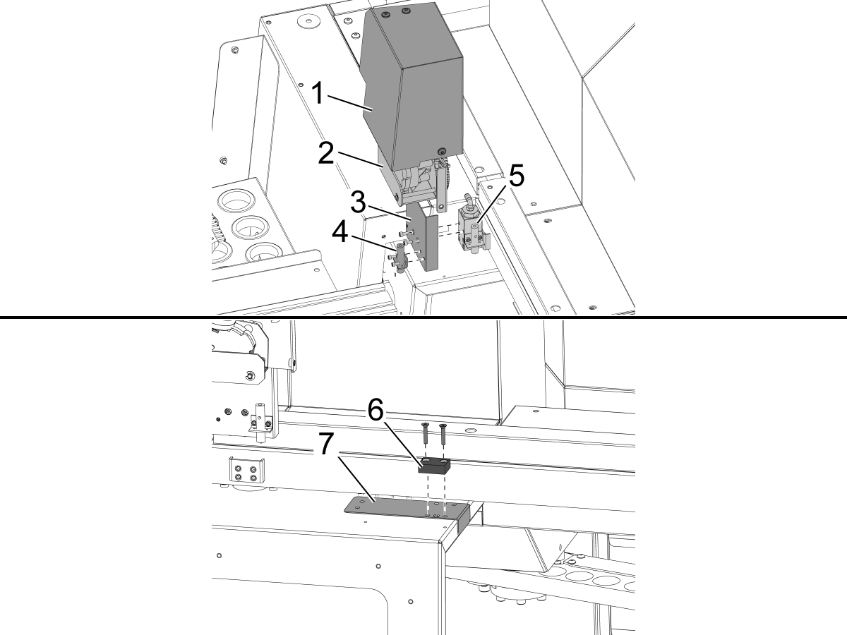
    Otomatik kapı motor kapağını [1] ve otomatik kapı motor grubunu [2] çıkarın.

    Yeni yakınlık anahtarı braketini [3] varolan yakınlık anahtarı bloğuna takın [5].

    Kapıyı her zaman brakete [3] açık yakınlık anahtarı [4] yükleyin

     Önemli: VMC kitine dahil edilmiş 2 matkap şablonu vardır. Bir VF şablonu [8] ve DC-2 makinelerine özgü benzersiz bir şablon [9] vardır. DC-2 makinelerinde standart VF şablonu yerine DC-2 şablonu kullanılmalıdır.

    Kapı açık bayrağı [6] için matkap kılavuzunu [7] takın ve kapının sacına 2x 10-32 delik açın ve kılavuz çekin.

    • Matkap boyutu: #21 veya 5/32"
    • 10-32 NF'ye dokunun

    Şablonu çıkarın ve 2x düz baş kapağı vidaları ile kapı açık bayrak yükleyin Otomatik kapı motor tertibatını, braketini ve kapağını yeniden kurun.

    Yakınlık anahtarı ile kapı açık bayrağı arasındaki yüksekliği ayarlamak için sağlanan şimleri kullanın.

    2

    Önden Yüklemeli Robot: 

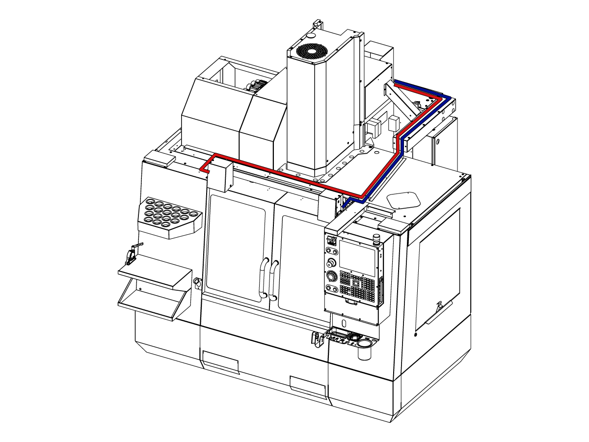
    Kapı tamamen açıkken kabloları resimde gösterildiği gibi kontrol kabinine yönlendirin.

    Makineyi kapatır.

    32-0807 PROX NO LEFT DOOR FULLY OPEN to SIO PCB P27‘ye bağlanın.

    32-0856 PROX NO RIGHT DOOR FULLY OPEN to SIO PCB P72‘ye bağlanın.

    Makineyi açın. 

    3

    Yandan Yüklemeli Robot:

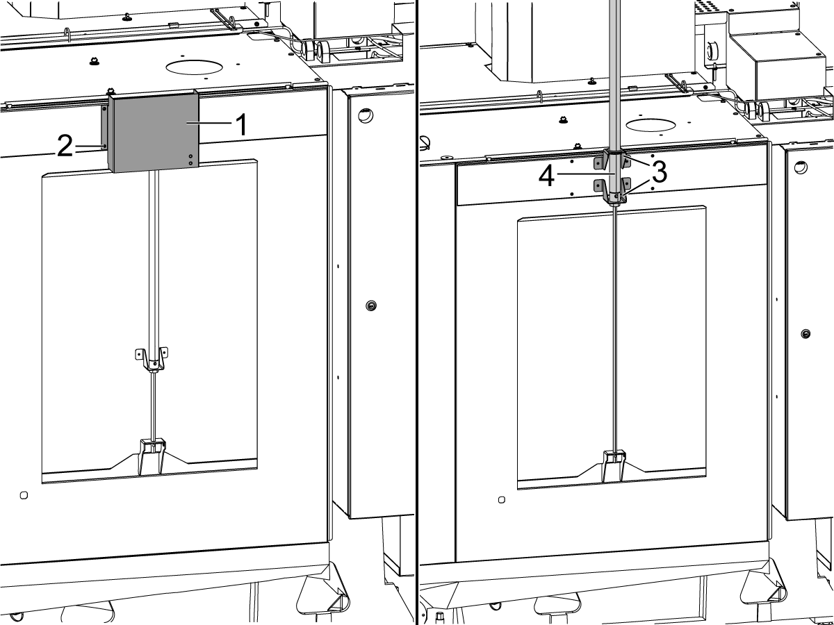
    Otomatik Pencerenin hava silindirini [4] açığa çıkarmak için kapağı [1] ve donanımını [2] çıkarın. Hava silindirini [4], braketler [3] ve hava silindiri gösterildiği gibi takılacak şekilde yükseltin.

    Verilen gri ve sarı hava kanallarını Otomatik Pencere hava silindirine bağlayın; hava silindirindeki bağlantı noktalarında, her borunun nereye bağlandığını gösteren gri ve sarı kablo bağları olacaktır.

    Kapağı [2] Otomatik Pencerenin hava silindirine takın.

    4

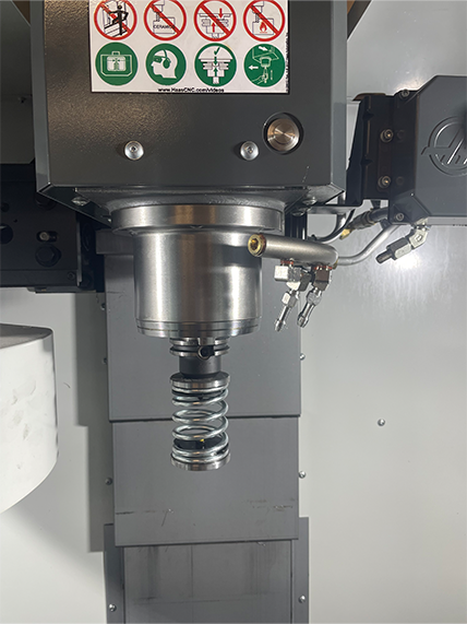
    • Yaylı itici ya 25mm veya 1" takım tutucu sığacak bir sapla yapılır
    • Bu takım, takım karuselinde bir takım tutucuyu doldurmalıdır.
    • Parçanın mengeneye düzgün bir biçimde oturmuş olduğundan emin olmak için herhangi bir programın başlangıcına aşağıdaki adımları programlayın:
      • Parçanın üstündeki yay iticisini bulun
      • Yay'ı yaklaşık 0,50 inç veya 12,7 mm sıkıştırmak için Z eksenini hareket ettirin
      • Mengeneyi bir saniyeliğine açın.
      • Mengeneyi bir saniyeliğine kapatın

    Not: Yay itici Parça Numarası: 

    • 30-12642 SPRING PUSHER.  25mm veya 1.0” tutucu ayrı satılır.

    Cobot Kurulumu

    1

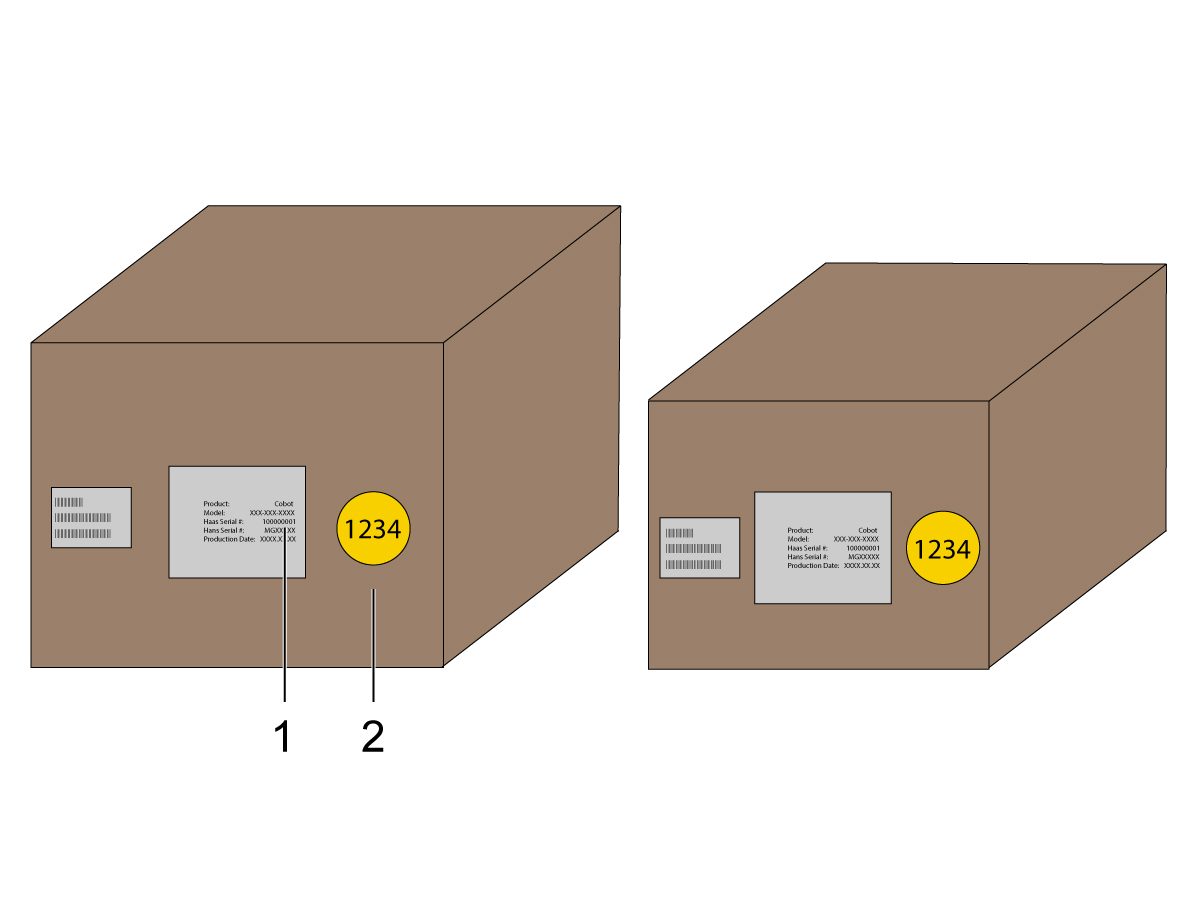
    Cobot ve kontrol kutusunun eşleşen seri numaralarıyla aynı eşleşen setten olduğunu doğrulayın.

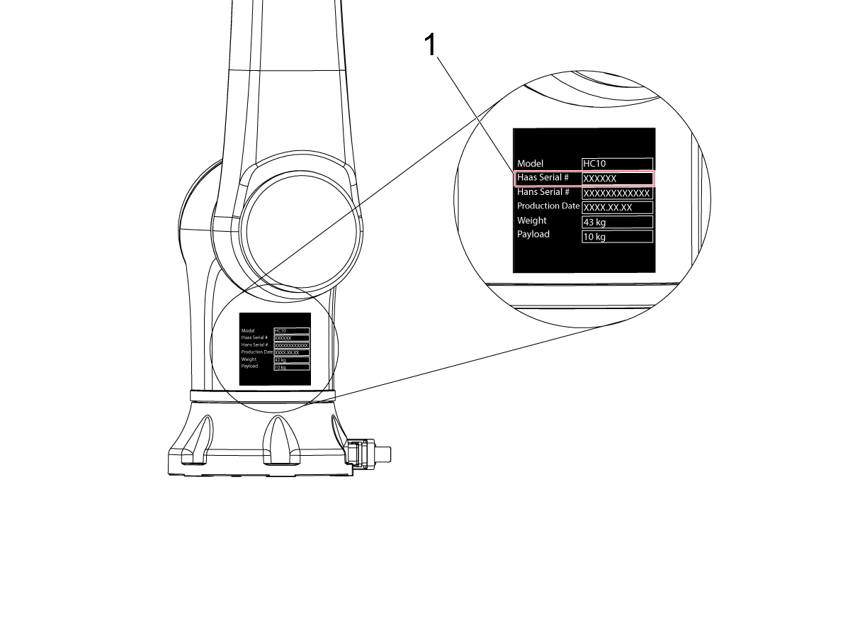
    Haas seri numarasının [1] yer aldığı bir çıkartma vardır. Bunların her iki kutuda da aynı olduğundan emin olun.

    Tanımlama numarası [2] olan sarı bir daire çıkartma vardır. Bunların her iki kutuda da aynı olduğundan emin olun.

    2

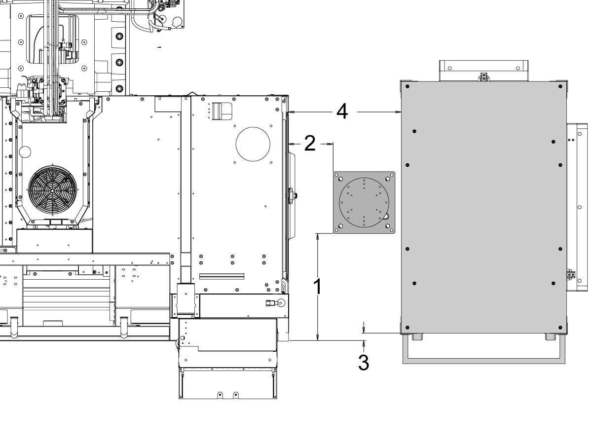
    Bu boyutları makinenin eteğinden kaidenin yan tarafına kadar ölçün.

     Not: Aşağıdaki boyutlar önerilen mesafelerdir. Pozisyon, kullanıcı uygulamasına bağlı olarak değişebilir.

    Sonraki adımlardaki boyutları ön ve yan yükleme cobot’ları için referans olarak kullanın. 

    Haas Cobot 10’un Haas Cobot kaidesi ile eşleştirilmesi önerilir. Bu kaide, Haas tarafından tanımlanan parça boyutu ve ağırlık limitlerine göre kullanıldığında yeterince sabit olacak şekilde yapılandırılmıştır. 

    3

    Önden Yükleme:

    Kaide ve parça tablasını makineye göre aşağıdaki konuma yerleştirin:

    Boyut İngiliz (İnç) Metrik (cm)
    Makinenin önünden kaidenin ön tarafına [1] 5,5 inç. 14 cm.
    Makinenin solundan kaidenin sol tarafına [2] 29,5 inç. 75 cm.
    Makinenin önünden parça tablasının ön tarafına [4] 22 inç. 56 cm.
    Makinenin solundan parça tablasının sol tarafına [4] 10 inç 25,4 cm.

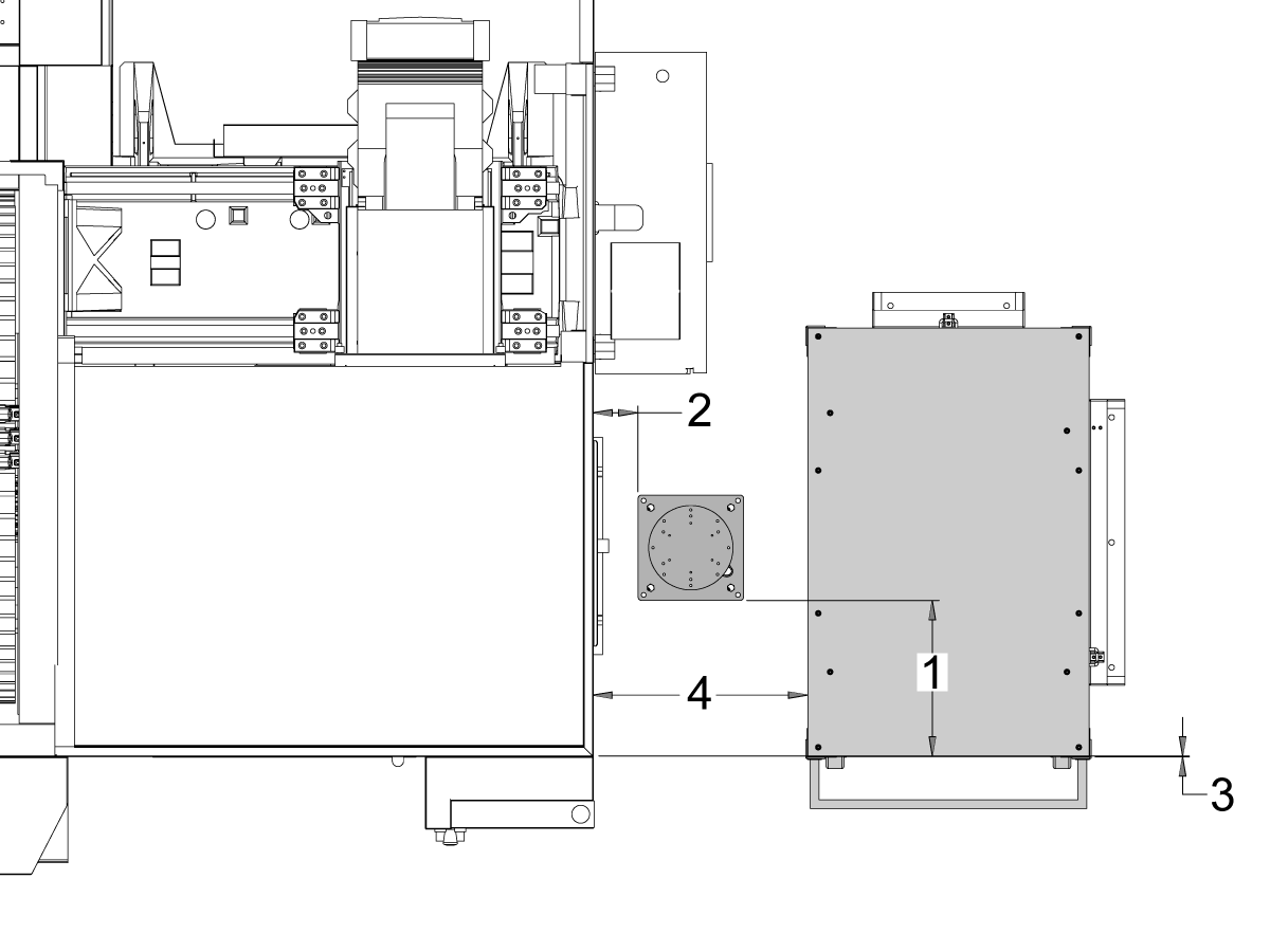
    4

    Yandan Yükleme:

    Kaide ve parça tablasını makineye göre aşağıdaki konuma yerleştirin:

    Boyut İngiliz (İnç) Metrik (cm)
    Makinenin önünden kaidenin sol tarafına [1] 20,5 inç. 52 cm.
    Makinenin sağından kaidenin ön tarafına [2] 8,5 inç. 21,6 cm.
    Makinenin önünden parça tablasının sol tarafına [3] 1,5 inç. 3,8 cm.
    Makinenin sağından parça tablasının ön tarafına [4] 21,5 inç. 54,6 cm.

    5

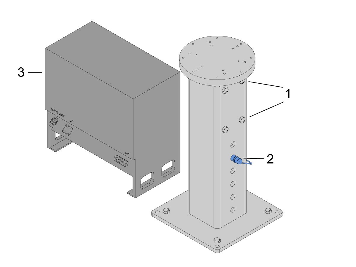
    Kaideyi zemine sabitleyin. Su terazisini kullanarak tablayı tesviye edin.

    NOT:Ayarlanabilir kaide için, ayar vidalarını [1] gevşeterek ve ardından kenetleme pimini [2] ayarlayarak istediğiniz yüksekliği ayarlayın. Robotu kurmadan önce ayar vidalarını [1] yeniden sıkın. Kaide üzerine bir su terazisi yerleştirin ve tabandaki (x4) altıgen cıvatayı kullanarak su terazisini X ve Y düzleminde ayarlayın.

    Kabloların yeterince gevşek olmasını sağlamak için Cobot kontrol kutusunu [3] doğrudan kaidenin yanına yerleştirin. 

    6

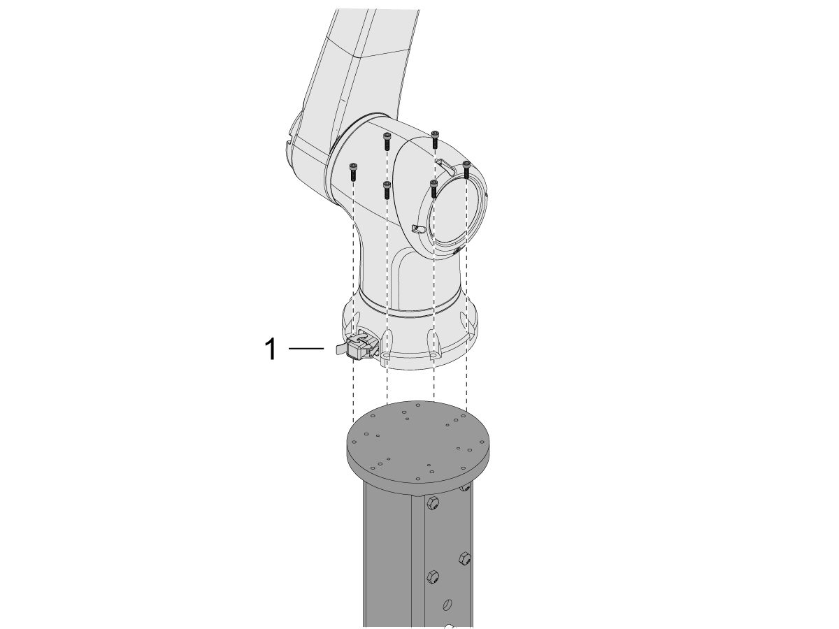
    Cobot'u taşıma kutusundan çıkarın.

    Not: Gerekirse adaptör plakasını kaideyle robot arasına takın.

    Cobot'u (x6) vidalarla kaidenin üzerine takın.

    NOT: Cobot kablo konektörünün [1] makinenin ön tarafına dik olduğundan emin olun. 

    ÖNEMLİ: Cobot yaklaşık 40 lb'dir ve bu ağırlığı güvenli bir şekilde kaldırabilen bir cihazla kaldırılmalıdır.

    7

    Cobot ambalajının içinde, aşağıdakiler de dahil olmak üzere yedek parçalarla doldurulmuş küçük bir torba [1] vardır: 

    • Sigorta
    • Vidalar (x2)
    • Kontrol Kutusu Anahtarları

    Ekstra M12 konektörüyle doldurulmuş orta boy bir torba [2] vardır. Bu kablo, Uç I/O Modülü için girişleri ve çıkışları yapılandırmak için kullanılabilir. 

    Kâğıtlarla doldurulmuş ve Cobot yazılımının indirilmiş olduğu bir USB bellek bulunan büyük bir çanta [3] vardır.

    Bu yedek parçaları ileride kullanmak üzere güvenli bir yerde sakladığınızdan emin olun. 

    Robot Elektrik ve Hava - Kurulum

     DANGER: Working with the electrical services required for CNC machines is extremely hazardous and can result in serious injury or death.

    Before connecting line wires to the CNC:

    • Turn off all power to the machine at the source.
    • Perform a Lockout-Tagout (LOTO) procedure to ensure the power remains off during service.
    • Verify that power has been disconnected by using an AC voltage detector on all incoming lines.

    If you are uncertain about how to safely disconnect power or perform LOTO procedures:

    • Do not proceed.
    • Contact qualified personnel or obtain appropriate assistance before continuing.

    Failure to follow these precautions may result in electrical shock, equipment damage, or fatal injury.

     Danger: Before beginning any work inside the control cabinet, verify that the High Voltage indicator light on the 320V Power Supply / Vector Drive has been off for a minimum of five (5) minutes. This waiting period ensures that residual voltage has dissipated and reduces the risk of electric shock.

    Certain service procedures involve high-risk electrical components and may pose serious injury or fatality hazards. Technicians must not attempt any procedure unless they have a complete understanding of the steps involved and the associated risks.

    If there is any uncertainty regarding a procedure, contact your Haas Factory Outlet (HFO) to arrange for a qualified service technician.

    1

    Arayüz Kutusunu Haas Makineye bağlama:

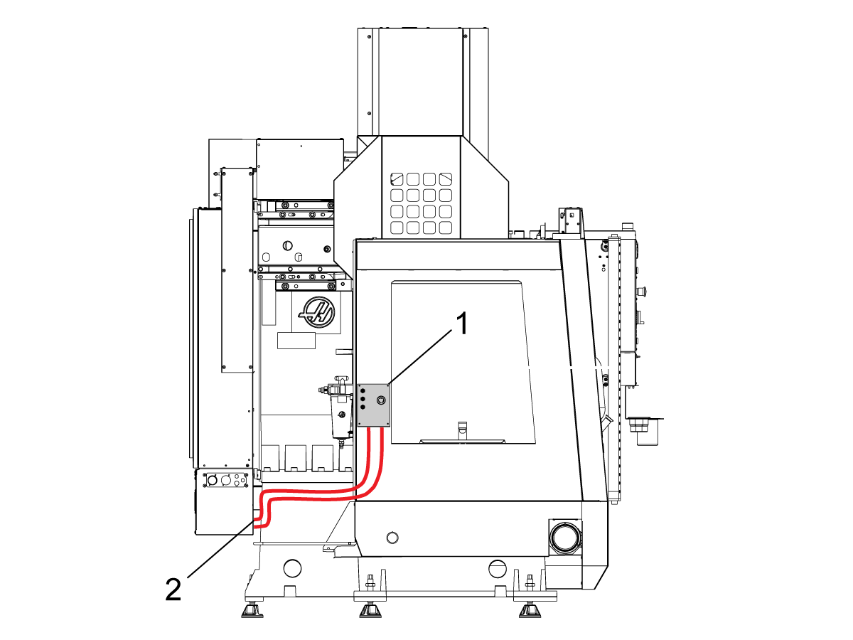
    Robot güvenlik cihazları arayüz kutusunda 32-9018, makine sacına takılması için manyetik bağlantılar bulunur. Arayüz kutusunu [1] şekilde gösterildiği gibi bağlayın.

    Arayüz elektrik kablolarını [2] manyetik montaj parçaları ve fermuarlar ile muhafaza boyunca yönlendirin. Kabloyu elektrik dolabının altından geçirin.

    NOT: Arayüz kutusunun Robot Güvenlik Cihazları Arayüz Kutusuna yükseltilmesi hakkında bilgi için bkz. Robot Güvenlik Cihazları Arayüz Kutusu - Kurulum - AD0703. 

    2

    Arayüz Kutusunu Haas Kontrol Kabinine Bağlama:

    33-8562C E-STOP terminal bloğunu TB-1B [1] konumuna bağlayın ve Kurulum modu terminal bloğunu SIO PCB üzerindeki TB-3B  [1] konumuna bağlayın.  

    Kullanıcı Rölelerini K9 ve K10’a [2] takın.

    Atlama parçasının JP1’de SIO PCB’ye takılı olduğunu doğrulayın.

    P1 SIO etiketli kabloyu P1’deki [3] SIO PCB'ye bağlayın.

    NOT:  Makinede Regen vektör sürücü varsa 33-0634 FILTER OV TO IOPCB P1 kablosunu P1 SIO’dan çıkarıp kablo 33-8562C üzerindeki FILTER OV FAULT konektörüne takın. Makinede bir Regen Vektör Sürücü  yoksaFILTER OV FAULT

    konektörüne hiçbir şey takmayın.

    RJ-45 kablosunu [4] Ethernet’e USB adaptörüne [5] (33-0636) bağlayın. USB konektör ucunu Maincon PCB J8 üst portuna bağlayın. USB adaptörüne bir ferrit filtre [6] ekleyin.

    24VDC Güç Kaynağını [7] kontrol kabininin sol tarafına takın ve 33-8562C kablosunu 24V PS etiketli konektöre takın.  33-1281 [8] ]kablosunu 24VDC Güç Kaynağına [7] bağlayın ve  PSUP PCB 

    üzerindeki  P3’e takın.

    3

    MM/SMM CM/CL makineleri için XMR olmadan

    P3, PSUP PCB'de P3 [10]'dan P7'ye [9] bağlı bir atlama parçası ile doluysa 24VDC güç kaynağının [7] PSUP'deki 120VAC konektörlerine bağlanmasına izin vermek için bir ayırıcı kablosu gereklidir. Ayırıcı kablonun erkek konektörünü P3'e [10] bağlayın ve ardından atlama parçasını bu kablodan P7'ye [9] ve ayrıca 33-1281 kablosuna [8] bağlayın.

    Not: Köprü kablosunun, ayırıcı kablosundan gelen kırmızı ile kırmızının hizalandığı yere bağlandığından emin olun.

    4

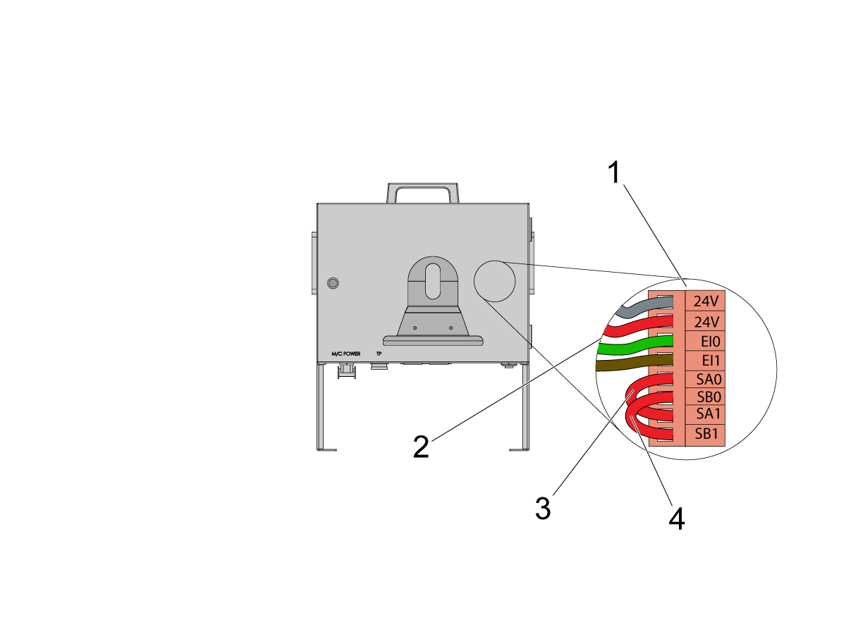
    Cobot kontrol kutusunun içine, robot sinyal kablosunun parçasını (33-1272 veya 33-1351) takın.  Bunu yapmak için, farklı renkli kabloları ilgili konumlarına takmak için güvenlik konektörünü [1] Cobot kontrol kutusundan çıkarın

    Güvenlik konektörüne giden 33-1272 / 33-1351 kabloları [2]:

    • Üst 24V'ye gri kablo
    • Alt 24V’ye kırmızı kablo
    • EI0'a yeşil kablo
    • EI1'e kahverengi kablo
    • SA0’dan SA1'a atlama parçası [3]
    •  SB0’dan SB1‘e atlama parçası [4]

     Not: Bu kablodan arta kalan kablolar kullanılmaz. Her kablo ucuna bir miktar elektrik bandı takın ve kalan kullanılmamış kabloları Kablo Bağıyla bağlayın. 

    5

    Önemli: Robot sinyal kablosuna ait tüm kabloları taktıktan sonra, Cobot kontrol kutusunu korumak için sigortanın [1] her zaman takılı olduğundan emin olun.

    6

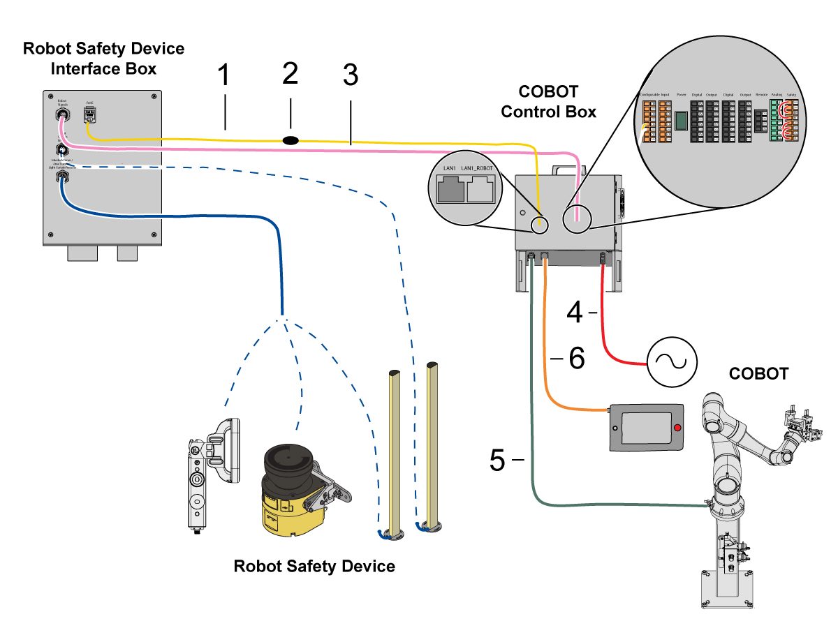
    Cobot'u Arayüz Kutusuna Bağlayın:

    RJ45 ethernet kablosunu [1] Cobot Kontrol Kutusundan arayüz kutusuna bağlayın. RJ-45 kablosuna bir ferrit filtresi [2] ekleyin. 

    Robot sinyal kablosunu [3] Cobot Kontrol Kutusundan arayüz kutusuna bağlayın. 

    120 VAC Cobot Güç Kablosunu [4] harici güç kaynağına bağlayın. 

    Robot güç kablosunu [5] kontrol kutusundan Cobot'a bağlayın.

    Kontrol kutusundan öğretici asılı kumanda kablosunu [6] öğretici asılı kumandaya bağlayın. 

    NOT: Kilitleme siperi, alan tarayıcısı veya ışık perdesi kurulumu hakkında daha fazla bilgi için bkz. aşağıdaki Robot Güvenlik Cihazı bölümü.

    7

    Uzaktan El Kumandasının makineye takılı olduğundan emin olun.

    NOT: RJH-XL kurulumu hakkında daha fazla bilgi için bkz. Uzaktan İş Kolu - Dokunmatik Büyük (RJH-XL) - Kurulum - AD0533. 

    8

    Adım 7 ila 10 arası, pnömatik kıskaçlar için kablo ve hortum yönlendirme talimatlarıdır. Mekanik kurulum için bu sayfanın alt kısmındaki kıskaç kurulumu bölümüne bakın.

    Çift hava solenoid grubunu, havayollarına yeterli gevşeklik sağlarken kaidenin yan tarafına takın. Yola çıkmayacağı bir konumda olduğundan emin olun. Hava hattını [1] gösterildiği gibi makinenin altından CALM kabinine doğru geri yönlendirin.

    9

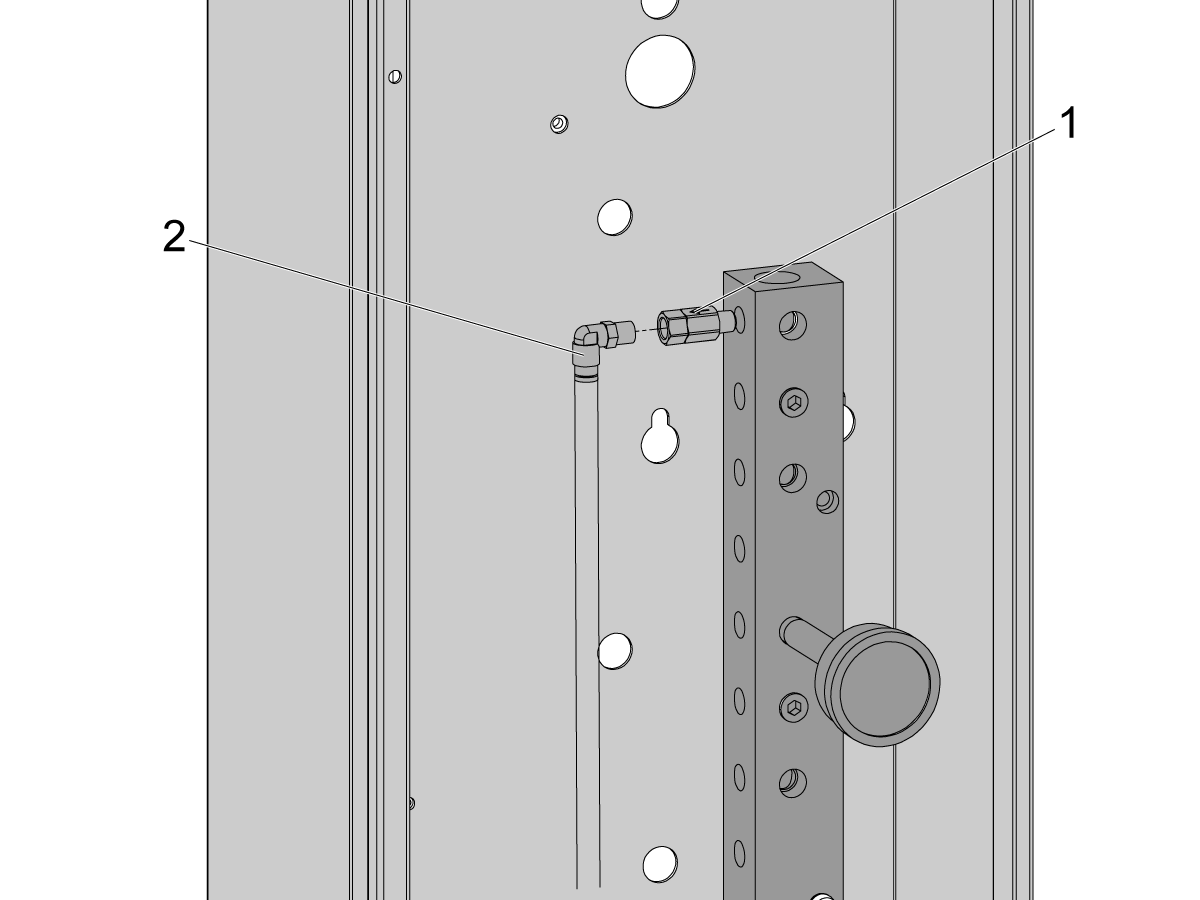
    CALM kabininin içinde, CALM manifold portlarından birinden bir tapayı sökün ve çek valfi [1] (58-1863) portun bağlantı elemanına takın. Giriş hava hattını [2] çift hava solenoid grubundan (önceki adımdan) CALM kabinine yönlendirin ve hava hattını çek valfe bağlayın.

    Makinenin hava kaynağını ON durumuna getirin.

    10

    Kontrol kutusunu [1] KAPATTIĞINIZDAN emin olun.

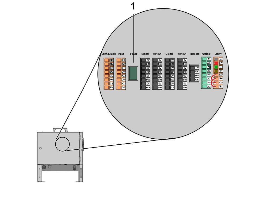
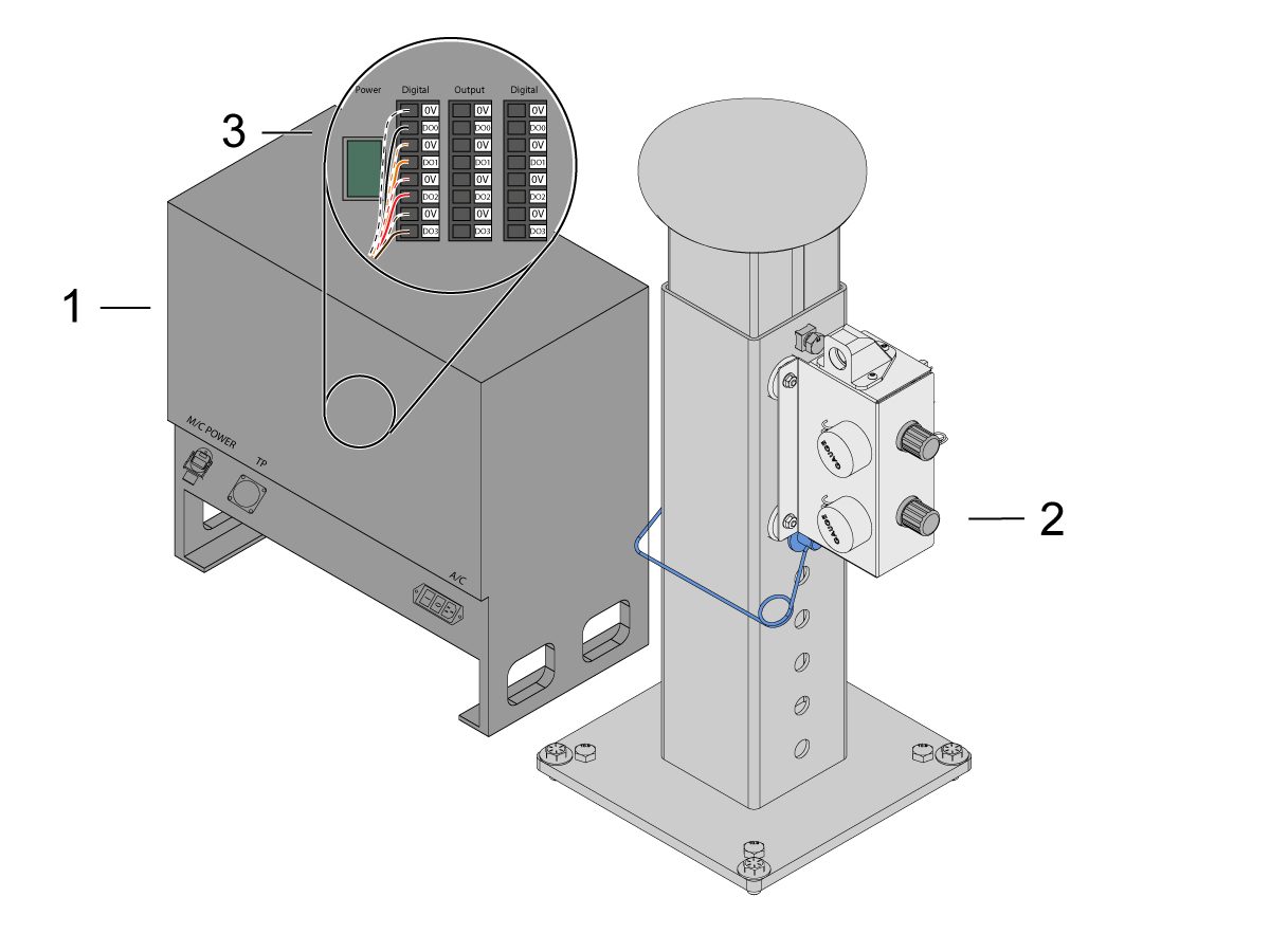
    Çift hava solenoid grubundan [2] gelen solenoid kablosunu Cobot kontrol kutusundaki [1] Dijital Çıkışa bağlayın. Konnektörü Cobot kontrol kutusundan sökün.

    11

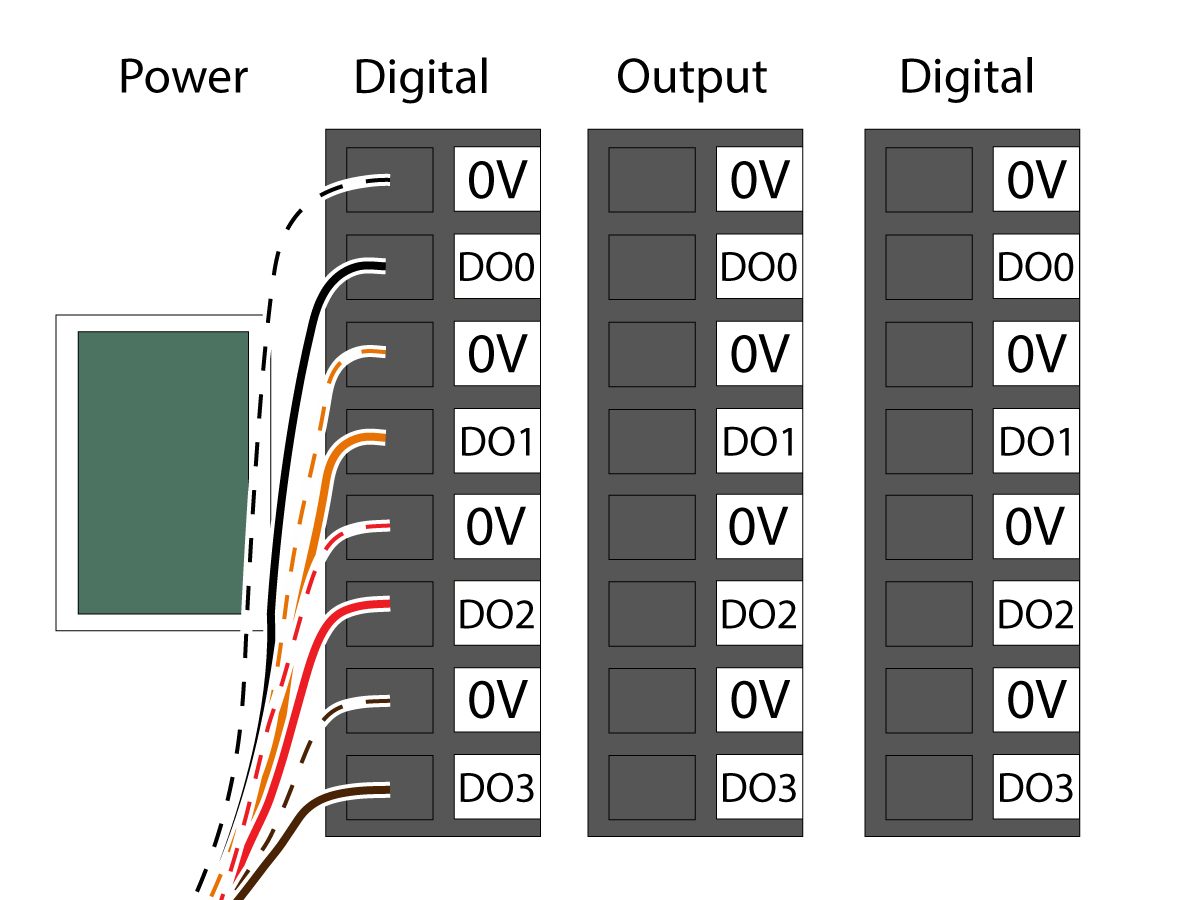
    Kıskaç solenoidi güç kablosunu (33-1276 / 33-1341) kontrol kutusu içindeki Dijital Çıkış terminaline bağlayın. Farklı renkli kabloları ilgili konumlarına takın:

    • 0V içine siyah/beyaz kablo
    • DO0 içine siyah kablo
    • 0V içine turuncu/beyaz kablo
    • DO1 içine turuncu kablo
    • 0V içine kırmızı/beyaz kablo
    • DO2 içine kırmızı kablo
    • 0V içine kahverengi/beyaz kablo
    • DO3 içine kahverengi kablo

    Kontrol kutusunu AÇIN.

    Robot Güvenlik Cihazı

    ÖNEMLI: GÜVENLİK CİHAZININ ÇALIŞMASINI DOĞRU ŞEKİLDE YAPILANDIRIP TEST EDENE KADAR ROBOTU ÇALIŞTIRMAYIN.

    Işık Perdesi:

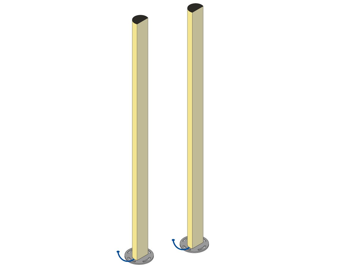
    Cobot paketleri, varsayılan güvenlik cihazı olarak ışık perdesi vericisi ve alıcısı ile birlikte verilir. Işık perdesi kurulumu için aşağıdaki prosedürü izleyin: 

    Işık Perdesi Kurulumu

    NOT: Alan tarayıcısı veya HC10 Makine Hazır kiti sipariş edilmişse, 1M ışık perdesi alıcısı ve vericisi de olacaktır. Bunlar tüm Cobot'larla birlikte verilir.

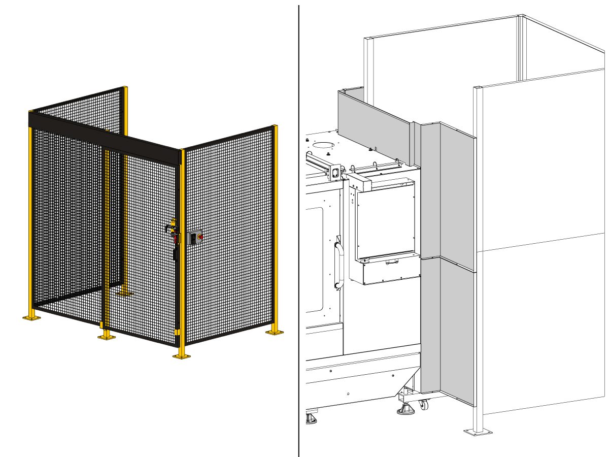
    Robot Siperi:

    Makine siper seçeneği ile donatılmış olarak geldiyse, robot siper ve kapı kilitleme tertibatının makineye takılması gerekir. Kurulum için aşağıdaki prosedürü izleyin:

    Robot Siperi Kurulumu

    Siper takıldıktan sonra, siper panelini makine ve robot siperi arasına takın.

    Alan Tarayıcısı:

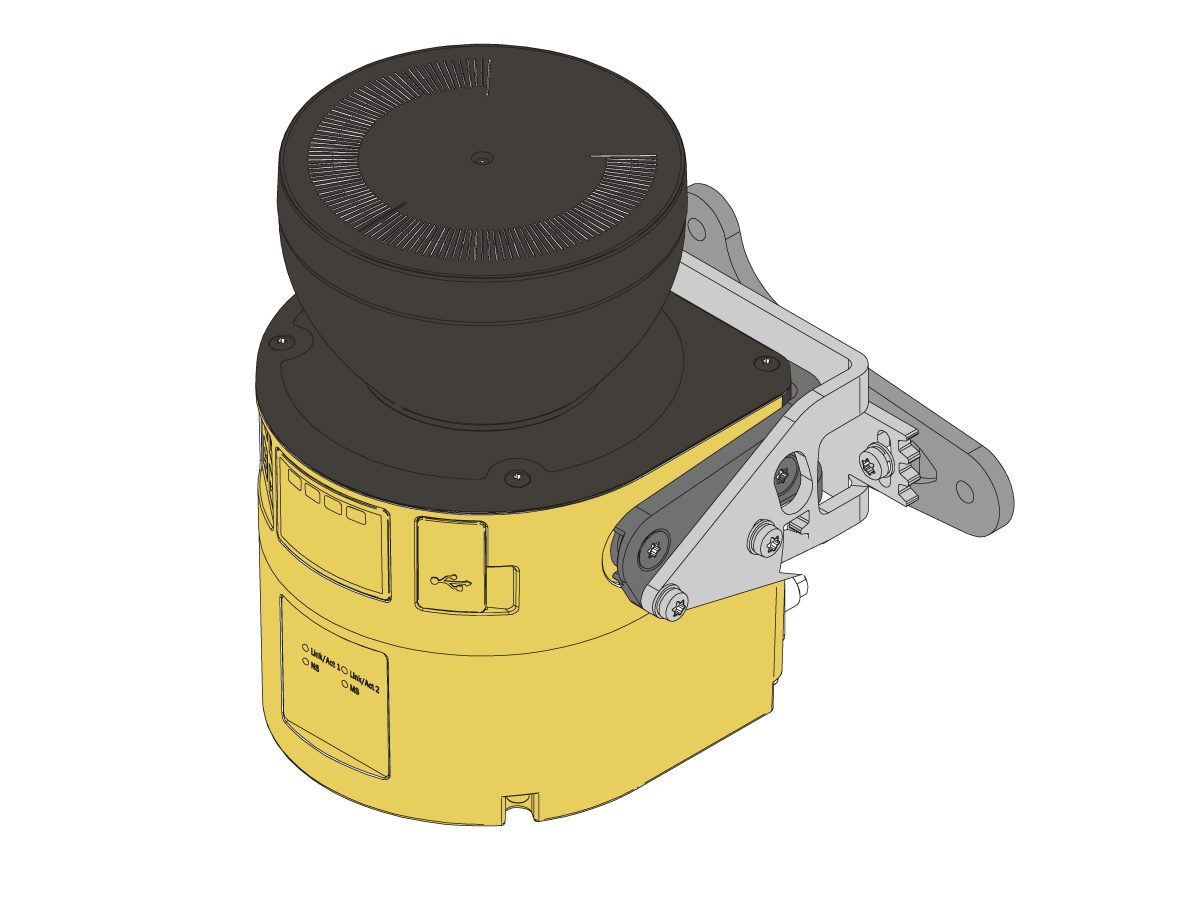
    Makine alan tarayıcı seçeneğiyle donatılmış olarak geldiyse, alan tarayıcısının kurulması ve alana yapılandırılması gerekir. Kurulum için aşağıdaki prosedürü izleyin: 

    Alan Tarayıcı Kurulumu

    İlk güç-UP

    1

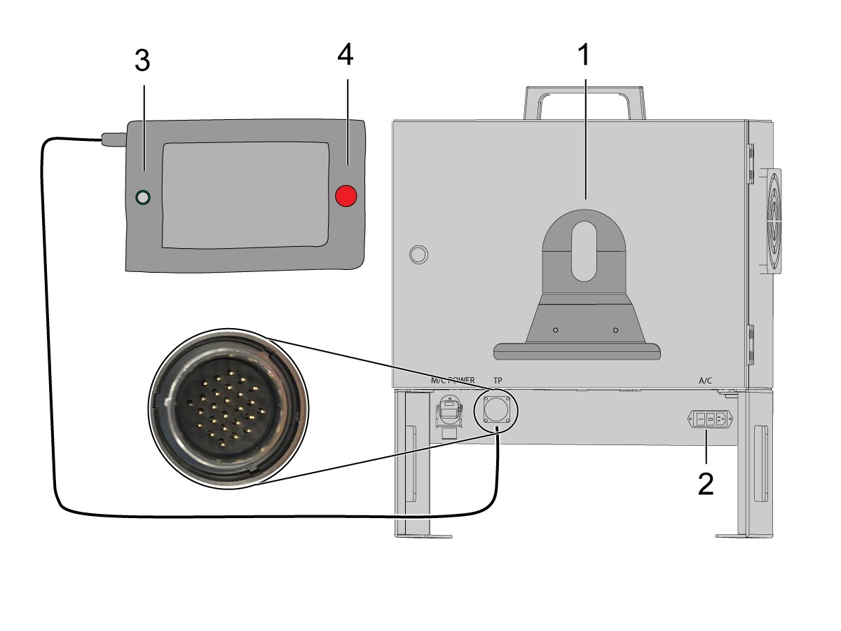
    Öğretici asılı kumanda tutucusunu [1] Cobot kontrol kutusunun önüne takın. 

    HAAS makinesini ÇALIŞTIRIN. 

    Güç anahtarını [2] çevirerek Cobot kontrol kutusunu AÇIN.

    Daireye [3] basarak Cobot öğretici asılı kumandasını AÇIN. 

    Öğretici asılı kumanda üzerindeki [E-STOP] [4] seçeneğinin serbest bırakıldığından emin olun. 

    2

    Not: Cobot öğretici asılı kumandada kullanıcı adı ve parolanın girilmesini isteyen bir açılır pencere olacaktır. Öğretici asılı kumandada oturum açmak için şu kimlik bilgilerini kullanın:

    • Kullanıcı adı = admin
    • Parola = admin

    Çalıştırma moduna geçin. Etkinleştir'e basın. 

    Elle Kumanda moduna [1] gidin.

    Her bağlantyı Sıfırı Taşı düğmeleri [2] ile sıfır konumuna taşıyın. 

    3

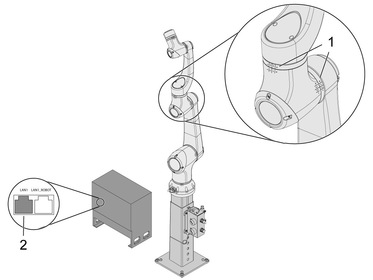
    Robot sıfır konumuna geldiğinde, karma çizgilerinin [1] Cobot üzerindeki her bağlantının her iki tarafında da hizalandığını doğrulayın. 

     ÖNEMLİ: Herhangi bir bağlantı karma hattı [1] hizalanmazsa, tüm karma hatları [1] hizalanana kadar buna göre elle kumanda edin. Bu konum, bir sonraki adımda yeni Cobot sıfır konumu olarak ayarlanacaktır.  

    Cobot kontrol kutusundan bir bilgisayara bir ethernet kablosu [2] bağlayın.

    Bilgisayarda, ethernet portunu etkinleştirmek için adaptör ayarını değiştirin. 

    Not: Adaptör ayarlarını değiştirme konusunda yardım için sonraki adımlara bakın.

    4

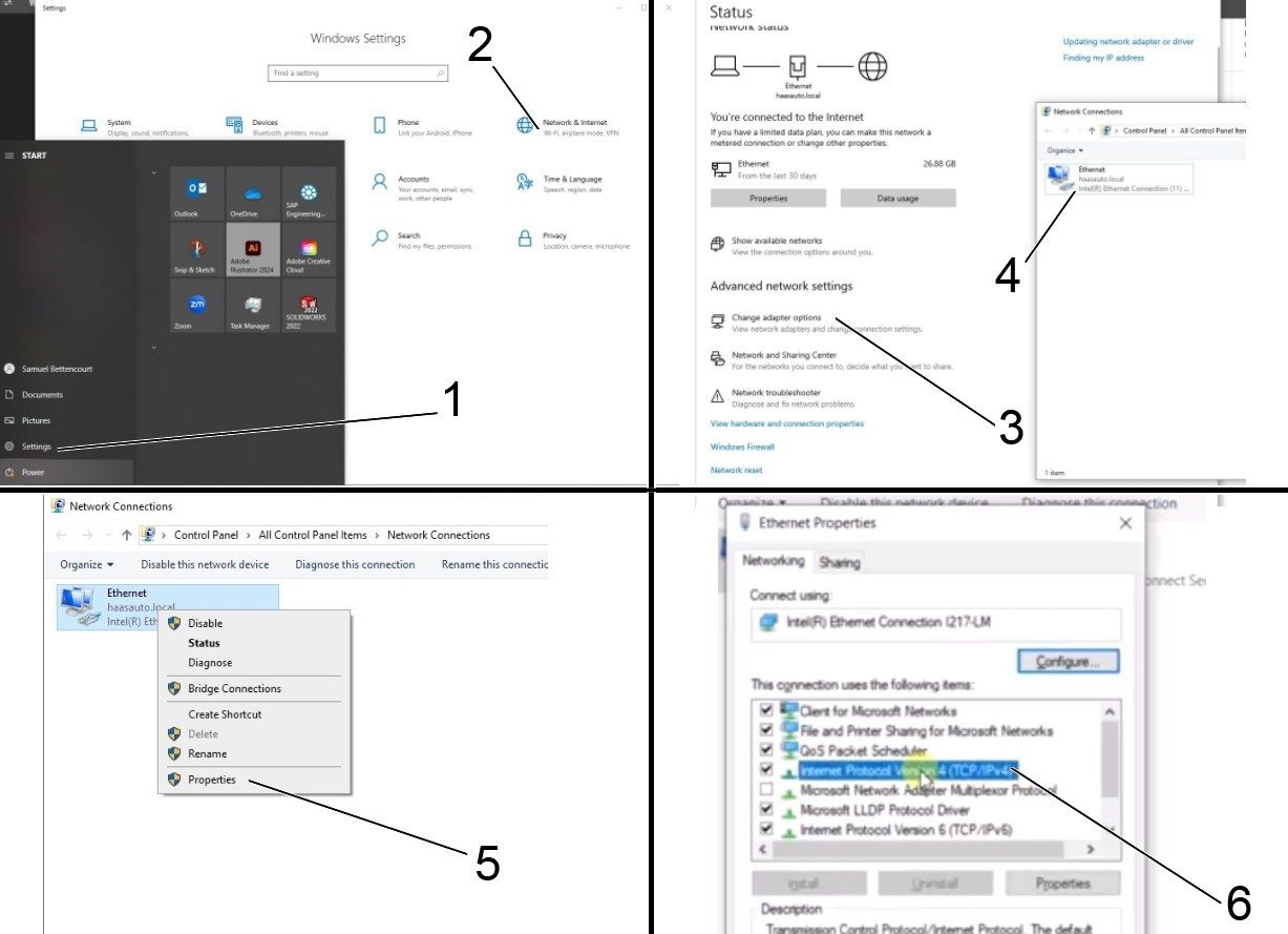
    Adaptör ayarlarını değiştirmek için, bilgisayardaki ayarlar sayfasını [1] açın, ardından ağ durumu sayfasını açacak olan Ağ ve İnternet [2] üzerine tıklayın.

    Adaptör seçeneklerini değiştir [3] üzerine tıklayın, sonra Ethernet [4] üzerine sağ tıklayın ve özellikler penceresini açın [5]. Buradan İnternet Protokolü Sürüm 4 (TCP/IPv4) [6] seçeneğini seçin ve Tamam'a tıklayın. 


    5

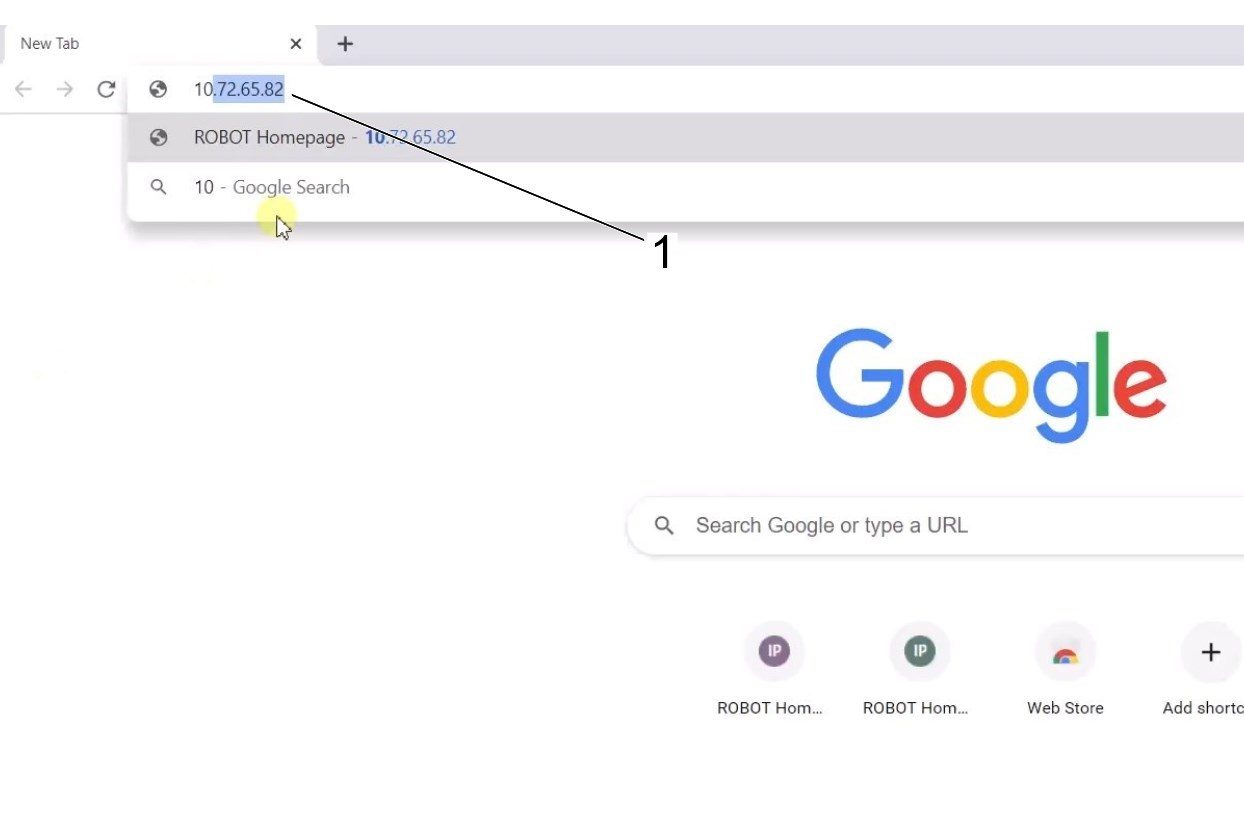
    Ethernet ayarları artık doğru olacaktır. Bir web tarayıcısı penceresi açın ve Cobot'un IP adresini yazın [1]. 

    Not: Bu, bir dizüstü bilgisayarı HRP-1/2/3'e bağlamakla aynı süreçtir. Cobota ethernet üzerinden bağlanma hakkında daha fazla bilgi için, Haas Robota Bağlan ve Elle Kumanda Et bölümündeki HRP-Sorun Giderme  sayfasındaki videoya bakın. 

    6

    HRTool’u HBC üzerinden indirin. HBC Servis bölümünde Yardımcı Programlar > Belgeler ve Yazılım > 01 Kontrol Yazılımı > 01 Yeni Nesil Kontrol > 10 Cobot Yazılımı > HRTool.zip.

    Klasörü açın ve HRToolsMaind.exe dosyasına gidin.

    Sistemler sekmesi altında bulunan Cobot IP adresini girin.  Ayarla’ya tıklayın. 

    HRTool üzerindeki Yapılandırma sekmesine gidin.

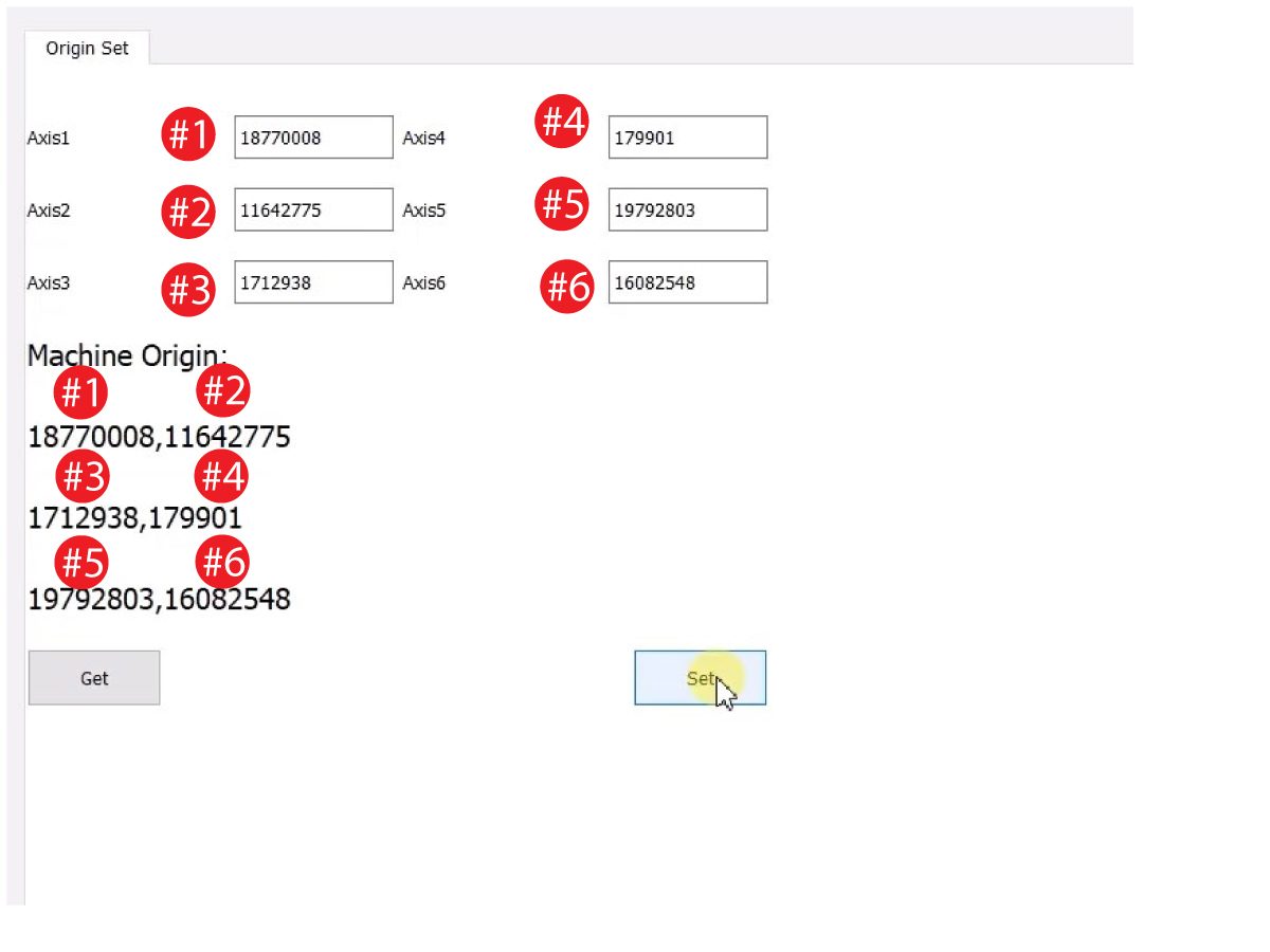
    Gerçek ve teorik enkoder değerlerini görmek için "al" seçeneğine tıklayın. 

    Teorik olan enkoder değerini gerçek olarak ayarlamak için "ayarla" seçeneğine tıklayın. Bu adım, Cobot'un o andaki konumunu yeni başlangıç konumu olarak ayarlar. 

    7

    Her bağlantının gerçek ve teorik enkoder değerlerinin eşleştiğinden emin olun. 

    NOT: Değerler eşleşmiyorsa, tekrar "Ayarla" seçeneğine basın. 

    8

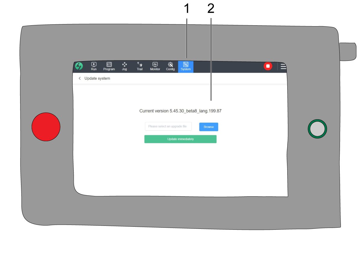
    Öğretici asılı kumandada, Sistem’e [1], ardından da Sistemi Güncelle'ye gidin. 

    Cobot aygıt yazılımının [2] aşağıdakilerden biri olduğunu onaylayın:

    • HR5.51H.16.beta.20231213.zip
    • HR6.4.9.tmp.20240919.zip

    NOT: Aygıt yazılımı sürümü HR6.4.9.tmp.20240919.zip, tüm boyuttan cobotlara uyumludur.

    Aygıt yazılımı güncelleme prosedürü için bkz. Haas Cobot - Bakım bölümü. 

    9

    Haas asılı kumandada tüm eksenleri referansa gönderin.

    Servis USB anahtarını takın.  Servis moduna gidin.

    Parametreler> Fabrika sekmesine gidin.  Aşağıdakileri değiştirin:

    • 1278 [1278:] Robot Hazır E-Stop TRUE olarak Etkinleştirildi
    • 2191 [694:] IŞIK PERDESİ TİPİ, LC_TYPE_1
    • olarak
    • 2195 [:] Ön Kapı Tam Açık Anahtarını Etkinleştir,  TRUE olarak
    • 2196 [:] Ön Kapı Tam Açık Anahtarını Etkinleştir, TRUE olarak
    • 2192 [:] Işık Perdesi Tetik Eşiği , 0
    • olarak

    SETTING (Ayar) düğmesine basın.

    Ayarları Yapın:

    • 372 - Parça Yükleyici Türü, 3 olarak: Robot.
    • 376 - Işık Perdesi Etkin, Açık
    • olarak ayarlandı

    10

    Haas asılı kumandada [CURRENT COMMANDS] tuşuna basın.

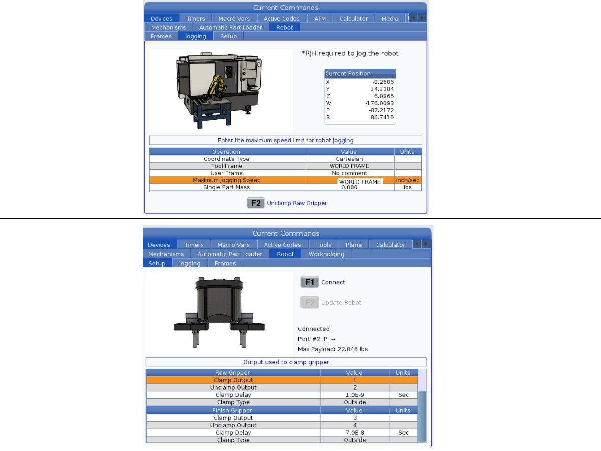
    Cihazlar>Robot>Elle Kumanda  sekmesine gidin. Aşağıdakileri değiştirin:

    • Maximum Jogging Speed (Maksimum Elle Kumanda Hızı) 7,9  inç/sn
    • olarak

     Not: RJH'deki elle kumanda artışları bu maksimum hız değerinin bir yüzdesidir. Robotun her elle kumanda tekerleği tıklamasıyla hareketini azaltmak için Maksimum Elle Kumanda Hızını daha düşük bir değer olarak değiştirmeniz gerekir.

    Kurulum sekmesine gidin. Aşağıdakileri değiştirin:

    • Maksimum Robot Hızı 118 inç/sn  (2000 mm/sn). 
    • Kıskacın Net Kütlesini girin. Bu ayar için doğru değeri almak üzere web sitemizdeki yerleşim çizimlerine (Tek Kıskaç yerleşim çizimi VEYA Çift Kıskaç yerleşim çizimi) bakın
    UYARI: Bu değerin yanlış ayarlanması Robot Kolunun doğru hareket etmemesine neden olabilir. 
     
    • Kıskaç Sayısı kıskaç sayısına göre.
    • Ham Malzeme Kıskacı Klamp Çıkışı 1
    • olarak.
    • Ham Malzeme Kıskacı Klamp Açma Çıkışı, 2 olarak.
    • Ham Malzeme Kıskacı Klamp Gecikmesi klamp/ayırma süresi sn olarak.
    • Ham Malzeme Kıskacı Klamp Tipi  OD/İD olarak.
    • Finiş Kıskacı Klamp Çıkışı, 3 olarak.
    • Finiş Kıskacı Klamp Açma Çıkışı, 4olarak.
    • Finiş Kıskacı Gecikmesi klamp/klamp açma süresi sn olarak.
    • Ham Malzeme Kıskacı Klamp Tipi  OD/İD olarak.

    Asılı Kumandayı Kapatma

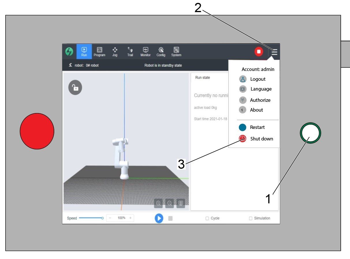
    Dikkat: Öğretici asılı kumandayı kapatmak için üzerindeki güç düğmesini [1] kullanmayın. Bu, Cobot kontrol kutusundaki sistem dosyalarının kaybolmasına neden olabilir.

    Öğretici asılı kumandayı kapatmak için, sağ taraftaki seçenekler menüsünü açmak amacıyla sağ üst köşedeki 3 satıra [2] basın.

    Cobot kontrol kutusu için güç KAPATMA sırasını başlatmak amacıyla Kapat seçeneğini [3] belirleyin.

    Önemli: Öğretici asılı kumandanın yanlış kapatılması Cobot kontrol kutusundaki kritik dosyaların hasar görmesine neden olabilir. Bu, sistem dosyaları kontrol kutusuna yeniden yüklenene kadar Cobot'un kullanılamaz hale gelmesine neden olabilir.


    Güvenlik Risk Seviyesi

    1

    ÖNEMLİ: Herhangi bir kurulumdan önce uygun bir risk değerlendirmesi yapılmalı ve uygun güvenlik gereklilikleri karşılanmalıdır. 

    2

    Risk değerlendirmesine dayanarak, Cobot öğretici asılı kumandasında uygun güvenlik riski seviyesini ayarlayın. Yapılandırma > Genel Kısıtlamalar öğesine gidin ve 0 - 5 arasında istenen güvenlik risk düzeyine [1] dokunun.

    Güvenlik seviyesini değiştirmek için güvenlik doğrulamasındaki "yönetici" kodunu kullanın.

    NOT: Güvenlik risk seviyesi daha düşük olduğunda, robot daha düşük bir maksimum hıza, kuvvete, vb. sahip olacaktır. Güvenlik risk seviyesi daha yüksek olduğunda, robot daha yüksek bir maksimum hıza, kuvvete, vb. sahip olacaktır. 

    Bu güvenlik risk seviyesi, Cobot'un Alarm 9150.10017 Çarpışma Durdurma Hatası tetiklenmeden önce dayanabileceği maksimum izin verilen kuvveti, hızı, gücü, momentumu, dirsek hızını ve dirsek kuvvetini [2] hesaplayacaktır. 

    ÖNEMLİ: Robotun programlanmış hızı, güvenlik riski seviyesinden izin verilen hızdan daha büyük olamaz. 

    NOT: Alarmlar hakkında daha fazla bilgi için bkz. Haas Cobot - Sorun Giderme Kılavuzu. 

    etkinleştirme

    1

    HAAS SERVICE PORTALI'na giriş yaparak yapılandırma dosyalarını indirip yükleyin.

    Güvenlik otomasyonu seçeneği ön/yan konfigürasyon dosyalarını indirin.

    Opsiyon konfigürasyon yama dosyasını kontrole yükleyin. Bkz.YENİ NESİL KONTROL - KONFİGÜRASYON DOSYASI - İNDİRME/YÜKLEME prosedürü. 

    2

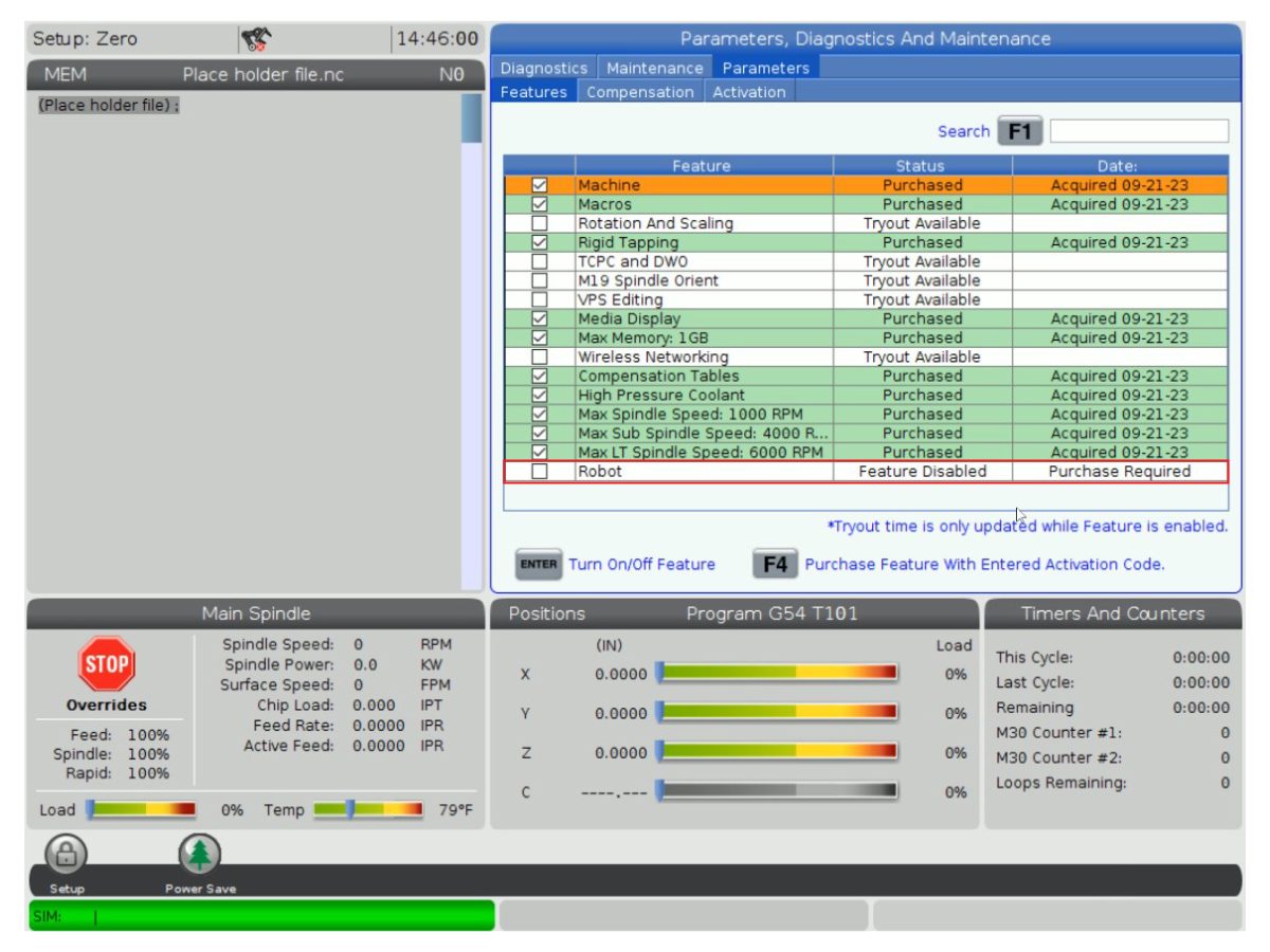
    Robot özelliğinin altta göründüğünü doğrulamak için Parametreler > Özellikler > Robot öğesine gidin.

    3

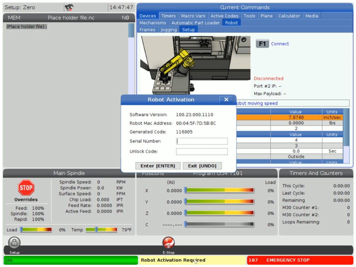
    [POWER ON] düğmesine basın.


    Cihazlar>Robot>Kurulum sekmesine gidin [1].

    [E-Stop]düğmesine basın.

    Robotu [2] bağlamak için [F1] tuşuna basın.

    Bir robotu bir makineye ilk kez bağlamak için robot özelliğinin kilidinin açılması gerekecektir. Bu açılır pencere makinenin mevcut makine sürümünü, robot mac adresini ve oluşturulan kodu gösterir. Kilit açma kodunu almak için bu bilgileri HBC'ye girin.

    4

    HBC'de, Servis sekmesine [1] gidin.

    Ekranın sol tarafında, Etkinleştirmeler [2] üzerine tıklayın ve ardından Cobot kilit açma kodunu almak için işlemi başlatmak amacıyla Cobot Kurulumu [3] öğesini seçin.

    İlk adım, HBC'deki alanlara Makine Seri Numarasını [4] ve Cobot Seri Numarasını [5] girmektir.

    Doğru bilgileri girdikten sonra, sağ alt köşedeki İleri [6] düğmesine basın ve kilit açma kodunu alana kadar adımlarla devam edin.

    Not: Robot Kurulumu sekmesinde değil, Cobot Kurulumu sekmesinde [3] olduğunuzdan emin olun. Robot Kurulumu sadece Haas Robot Paketleri için kullanılır. Haas Cobot’lar için Robot Kurulumunun kullanılması geçersiz bir kilit açma koduna neden olacaktır.

    5

    Robotu makineye bağlamak için Cobot'un Haas Seri Numarasını [1] ve kilit açma kodunu girin. 

     Not: Bu adım yalnızca bir HFO Servis Teknisyeni tarafından tamamlanabilir.

     Not: Cobot etkinleştirilmeden önce makinenin etkinleştirilmesi gerekir.  Makine Etkinleştirme / Süre Uzatma - NGC  prosedürünü izleyin.

    Robot makineye bağlandığında, Haas ekranının alt kısmında Robot Etkinleştirme Başarılı yazan sarı bir mesaj görünmelidir.

    6

    Alarmı kaldırmak için [E-STOP] düğmesini bırakın ve RESET düğmesine basın. 

    [HANDLE JOG] düğmesine basın. 

    [CURRENT COMMANDS] tuşuna basın ve -Cihazlar > Robot > Elle Kumanda sekmesine gidin.

     Not: Ayar modundaki robota sadece  F2  tuşu RJH’a basıldığında elle kumanda edilebilir. Aşağıdaki Kurulum/Çalıştırma modu bölümüne bakın.

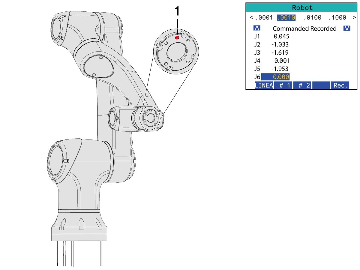
    Uzaktan Kumanda Kolu Jog Touch üzerinde, Eklem Koordinatlarına gitmek için Eklem düğmesine basın.

    Kıskaçları takmak için robotu erişilebilir bir yere taşıyın.

    J6’yı elle kumanda ile 0.0000 pozisyonuna getirin.

    Yerleştirme deliği üste ortalanmalıdır.

    Not: Robot üzerinde çalışmadan önce [Emergency Stop] tuşuna basın.

    Kıskaç Kurulumu

    1

    Hava/Yağ kabinindeki vanayı çevirerek makine havasını kapatın ve sistemdeki havayı boşaltmak için basınç tahliye vanasını çekin.

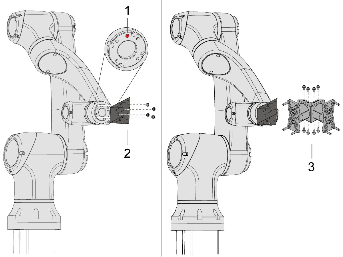
    2

    Çift Hareketli Kıskaç için:

    Bu bölüm için her ikisi de aynı kurulum işlemine sahip iki adet çift hareketli kıskaç versiyonu vardır.

    Robotu, konum deliği [1] üstte ortalanacak şekilde elle kumanda edin.

    Adaptör plakasını [2] robot kolunun ucuna takın.

    Çift kıskaç grubunu [3] adaptör plakasına [2] takın.

    NOT: 

     Kıskaç 1’i (turuncu ve mor kablo bağları vardır) Kıskaç 1 adaptör plakası bölümüne taktığınızdan emin olun.

    3

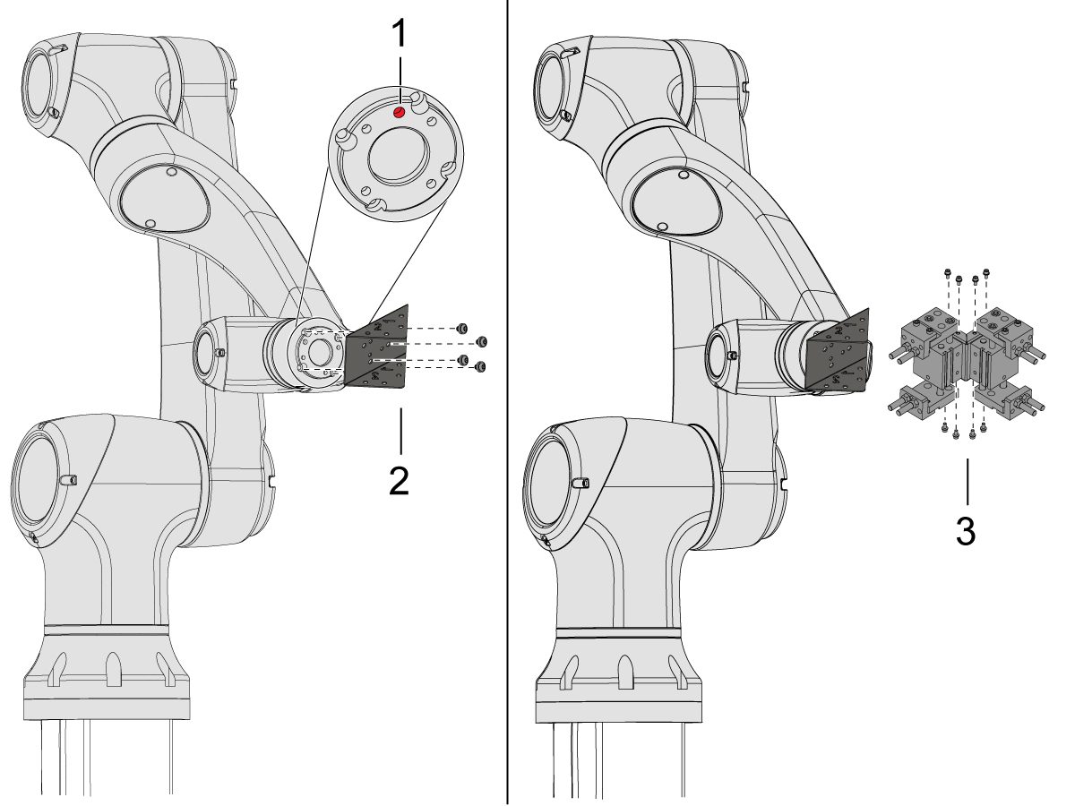
    Açılı Tek Hareketli Kıskaç için:

    Robotu elle kumanda edin, böylece konum deliği [1] üstte ortalanmalıdır.

    Açı adaptör plakasını [2] robot kolunun ucuna takın.

    Tek kıskaç grubunu [3] açı adaptör plakasına [2] takın.

    4

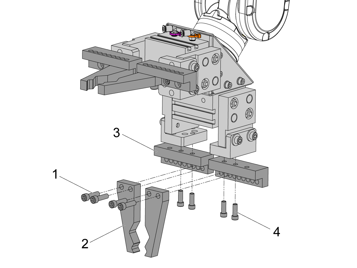
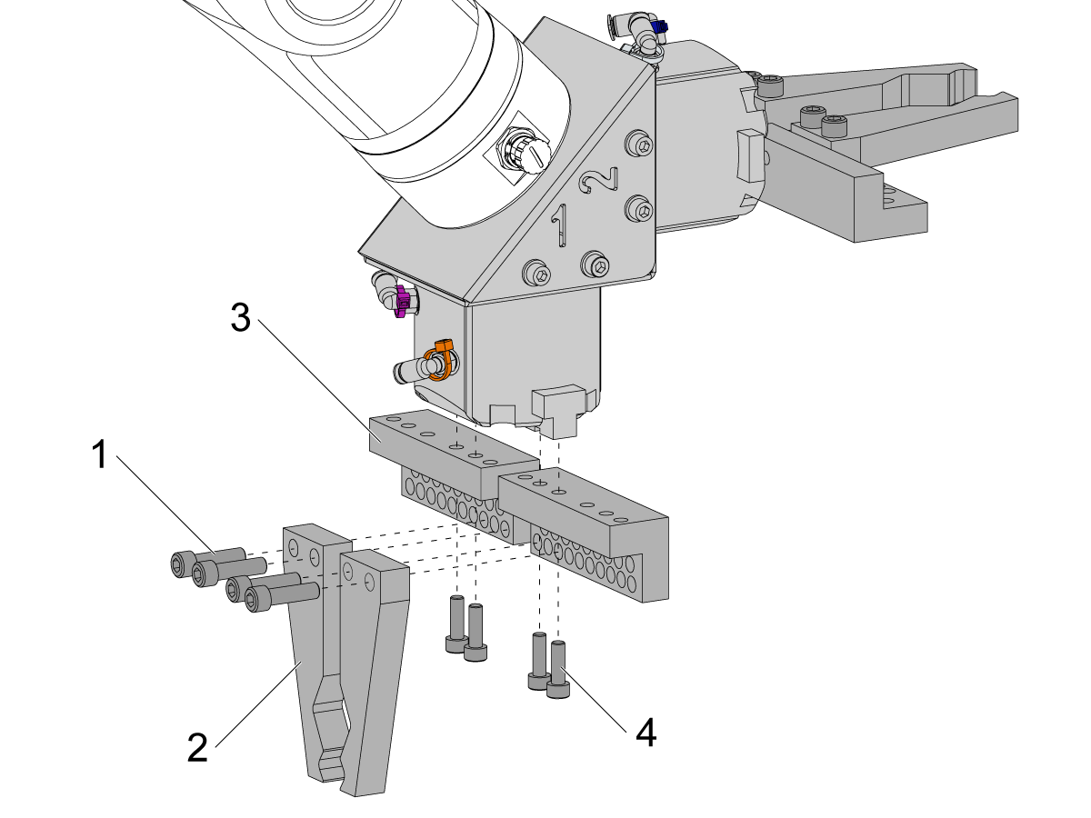
    Çubuk kıskacı parmaklarını takmak için, küşçe kıskaç plakalarını kıskaç gövdelerinden çıkarın.

    Çubuk Kıskaç Plakalarını [3] (x8) SHCS M6 vidaları [4] ile takın. 10 ft-lbs torkla sıkın.

    Çubuk Kıskaç Parmaklarını [2] (x8) SHCS 1/4-20 [1] ile takın. 13 ft-lbs torkla sıkın.

    5

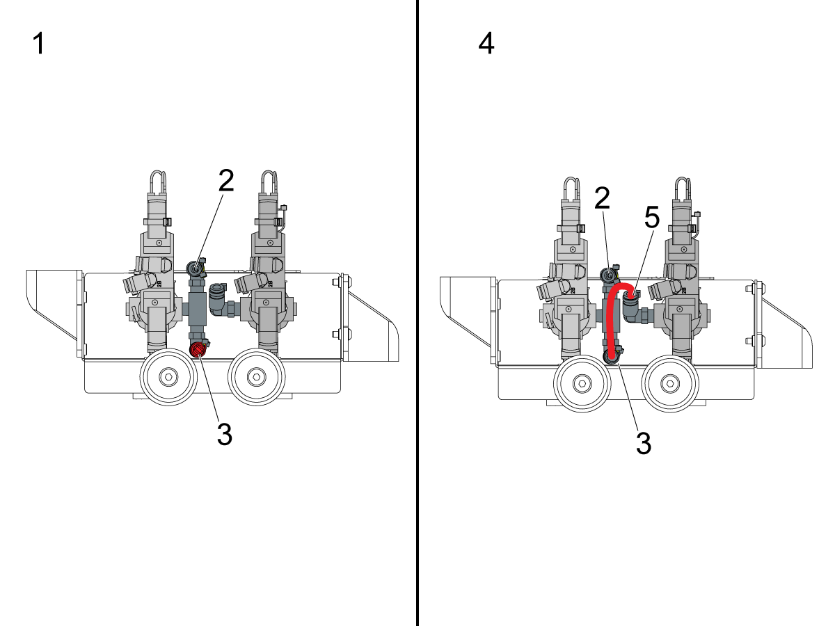
    Tek [1] veya solenoid [2] kıskaç konfigürasyonuna bağlı olarak pnömatik kıskaçlar için kullanılan çift hava solenoidini yapılandırın. 

    Tek kıskaçlar [1] için, gelen havayı bağlantı parçasına [2] bağlayın ve fişi resimde gösterildiği gibi bağlantı parçasının [3] diğer ucunda tutun.

    Çift kıskaçlar [4] için, bağlantı elemanındaki [3] tapayı sökün ve ikinci solenoide [5] küçük bir hava hortumu takın. Daha sonra gelen hava hortumunu bağlantı elemanına [2] bağlayın, böylece her iki solenoid de hava alır.

    6

    Tek Kıskaç için:

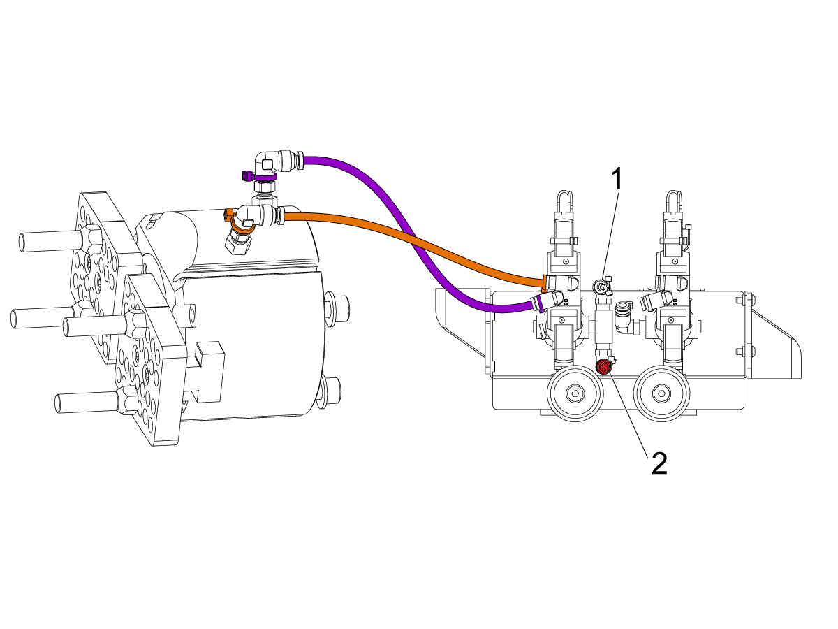
    (x2) hava hatlarını kıskaçtan çift hava solenoid grubu üzerindeki aynı renk kodlu rakora yönlendirin. 

    Hava hatlarını kablo kanalına sararak sabitleyin. Kablo kanalını cobot’a bağlamak için cırt cırtlı kayışları kullanın. Cobot tamamen uzatıldığında kabloların gerilmemesi için yeterli gevşeklik olduğundan emin olun.

    Giriş hava hortumunu kullanılan solenoidin bağlantı elemanına [1] takın. 

    Tapanın kullanılmayan solenoidin bağlantı noktasına [2] takılı olduğundan emin olun. 

    7

    Çift Kıskaç için:

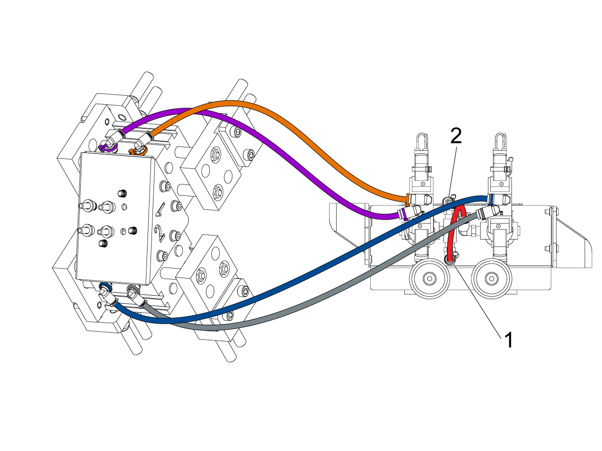
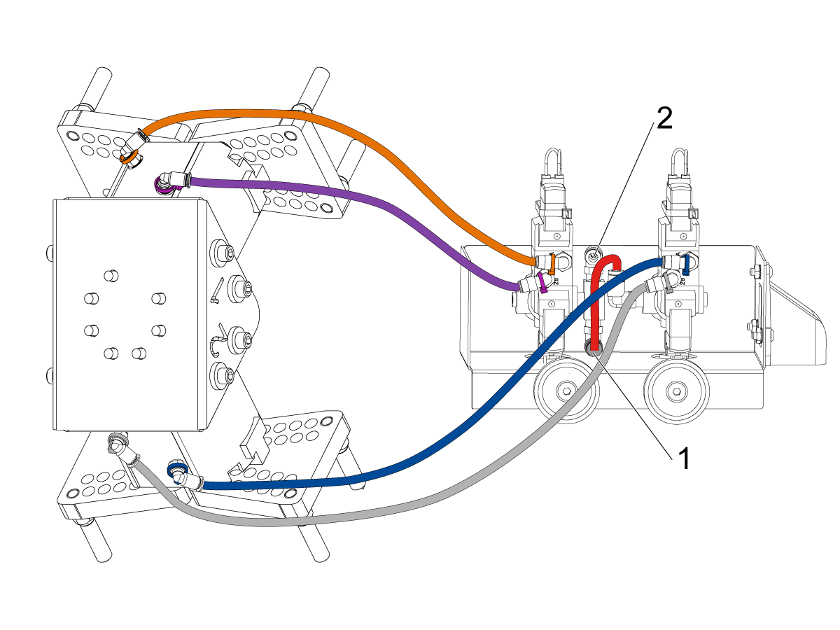
    (x2) hava hatlarını kıskaç #1 çift hava solenoid grubu üzerindeki aynı renk kodlu rakora yönlendirin. 

    (x2) hava hatlarını kıskaç #2 çift hava solenoid grubu üzerindeki aynı renk kodlu rakora yönlendirin. 

    Hava hatlarını kablo kanalına sararak sabitleyin. Kablo kanalını cobot’a bağlamak için cırt cırtlı kayışları kullanın. Cobot tamamen uzatıldığında kabloların gerilmemesi için yeterli gevşeklik olduğundan emin olun.

    Birinci solenoidi ikincisine bağlayan kısa hava hattını [1] takın. 

    Giriş hava hortumunu bağlantı elemanına [2] takın. 

    Parça Tablası Montajı

    Parça tablası seçeneği sipariş edilmişse, montaj talimatları için aşağıdaki prosedürü izleyin:

    Haas Robot - Parça Tablası Montajı

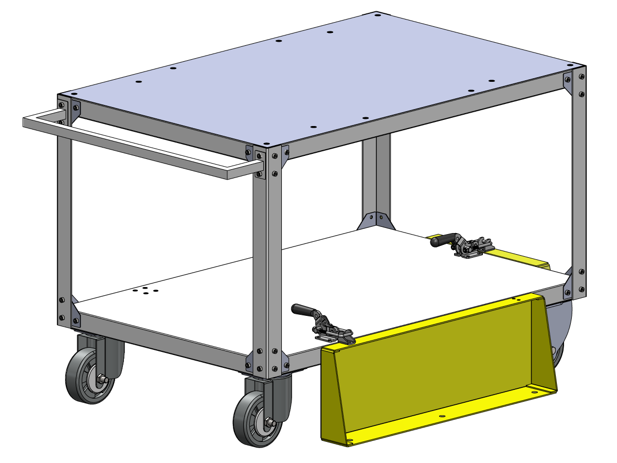
    NOT: HC10 MACHINE READY KIT satın alınmışsa ve parça tablası doğrudan ahşap palete monte ediliyorsa tekerleklerin takılmasına gerek yoktur. 

    Doğrulama

    Acil durdurmayı test edin:

    • Haas Asılı Kumanda, RJH-XL ve Cobot Öğretici Asılı Kumandada bulunan her E-STOP düğmesine basın. Makinenin 107 ACİL DURDURMA alarmı oluşturduğundan emin olun.  ACİL DURDURMA düğmesi 107 ACİL DURDURMA alarmını üretmediği takdirde, kablo tesisatını kontrol edin. RJH-XL’yi etkinleştirmek için en son konfigürasyon dosyalarını yükleyin.

    Robot Güvenlik Cihazını Test Edin:

    Robot güvenlik cihazı tetiklendiğinde Haas asılı kumanda butonunda bir E-STOP veya ışık perdesi tetiklendi simgesi olduğundan emin olun. 

    • Siper- Anahtarı kilitde takın, kilidin önündeki iki kırmızı LED ışığının KAPALI olduğunu doğrulayın. Anahtarı kilitten çıkarın, iki kırmızı LED ışığının AÇIK olduğunu doğrulayın. 
    • Alan Tarayıcısı - Koruyucu alanın içine adım atın, alan tarayıcısında kırmızı LED'in yandığını doğrulayın. Koruyucu alanın dışına çıkın, yeşil LED'in yandığını doğrulayın.
    • Işık Perdesi- Işık perdesi ışınlarına müdahale edin, Haas asılı kumanda butonunda ışık perdesi tetiklendi simgesinin göründüğünü doğrulayın. [RESET] düğmesine basın. Işık perdesi ışınlarının dışına adım atın, Haas asılı kumandada hiçbir simgenin olmadığını doğrulayın. 

    NOT: Işık perdesi tetiklendi simgesi gösterilmiyorsa, kablo tesisatını, hizalamayı ve şu fabrika ayarını doğrulayın: 2191 [694:] LIGHT CURTAIN TYPE , LC_TYPE_1

    olarak ayarlanmış.

    Kıskaçların Çalışmasını Test Edin:

    • Kıskaçların her ikisinin de doğru şekilde klamplendiğini ve ayrıldığını doğrulayın.
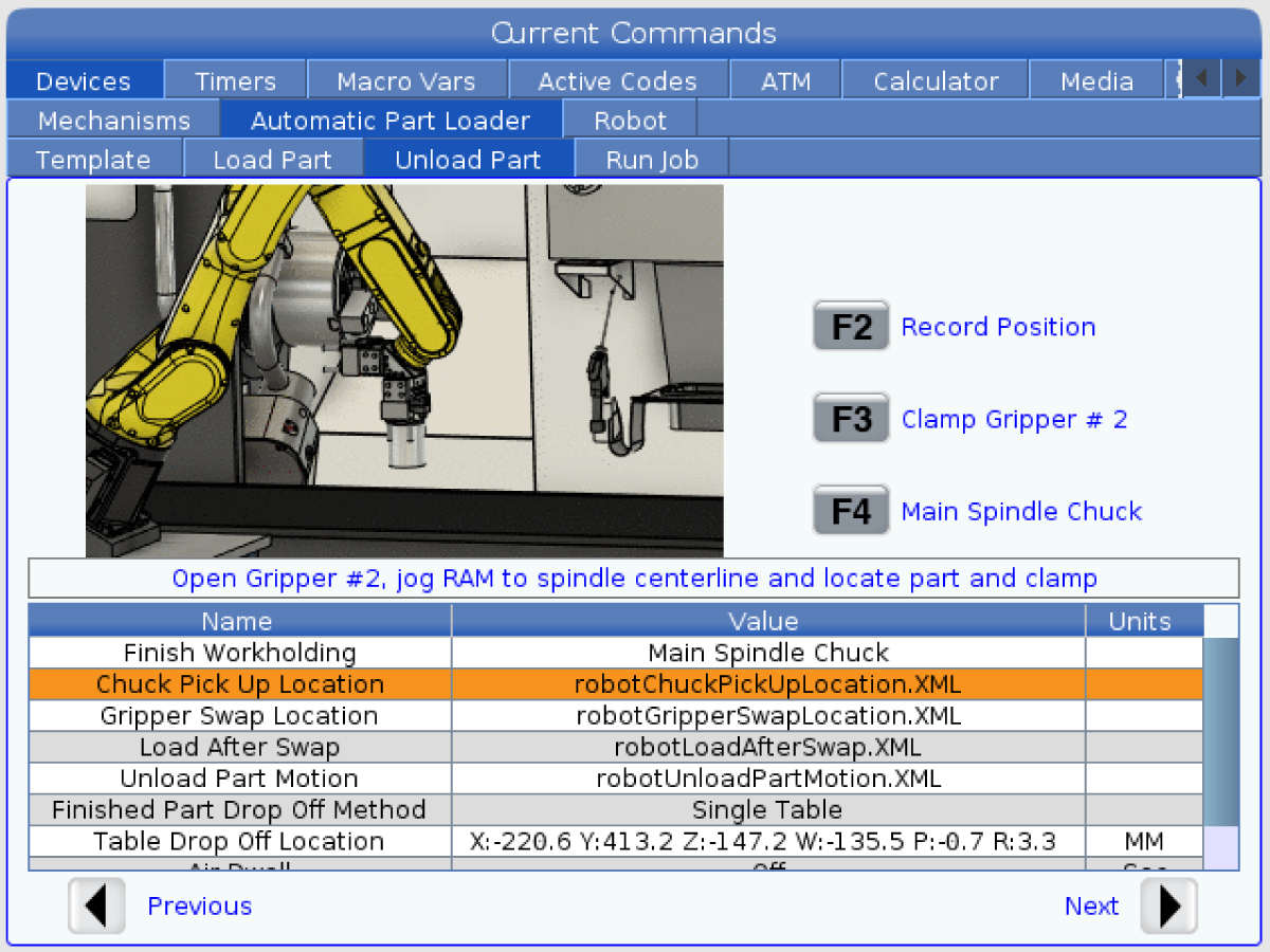
    • [CURRENT COMMANDS] tuşuna basın ve - Cihazlar > Robot > Elle Kumanda sekmesine gidin.
    • Finiş Kıskacını klamplamak/klamplamayı kaldırmak için [F2] düğmesine basın.
    • Ham Malzeme Kıskacını klamplemek/ayırmak için [F3] tuşuna basın.

    Uzaktan El Kumandasını test edin.

    • Uzaktan El Kumandasını Çıkarın
    • [HANDLE JOG] düğmesine basın. 
    • [CURRENT COMMANDS] tuşuna basın ve - Cihazlar > Robot > Elle Kumanda sekmesine gidin.
    • Uzaktan Kumanda Kolu üzerinde, Eklem Koordinatlarına gitmek için Eklem düğmesine basın.
    • Robotu güvenli bir konuma taşıyın.

    ÖNEMLİ: Robotu çalıştırmaya çalışırken "Lütfen Işık Perdesini veya Güvenli Hücre çalıştır" yazan sarı bir uyarı mesajı görünürse, HBC'den konfigürasyon dosyalarını yeniden yükleyerek güvenlik parametresinin uygulandığını doğrulayın. 

    Güvenli/Çalıştırma Modunun Çalıştırıldığını Doğrulayın

    Tüm Haas CNC makineleri kurulum modunu kilitlemek ve kilidini açmak için asılı kumanda butonunun yan tarafında bir şaltere sahiptir. Robot, hangi modun seçildiğine bağlı olarak aşağıdaki davranışlara sahip olacaktır. 

    • Haas kontrol ünitesi Çalıştırma modundayken, mod 1, robot güvenlik cihazının tetiklenmesi tüm hareketi durdurur. Robot güvenlik cihazı tetikleninceye kadar bu hareket başlatılamaz.
    • Haas kumandası Kurulum modundayken, mod 2, robotun hareket yolunu programlamak, pozisyonu almak, bir robotun takım merkezi noktasını ayarlamak, (bir ofset), tezgahtaki iş milinden veya parça tutucudan parçaları yüklemek ve almak vb. için robotun bir eksenini elle kumanda etmek gibi sınırlı hız hareketi gerçekleştirilebilir. Programlanan yol, robotun programlanan yolunu kanıtlamak için yavaş çalışabilecektir. Ayar modundaki robota sadece F2 düğmesi RJH’a basıldığında elle kumanda edilebilir.

    Haas Robot - Hızlı Başlangıç Kılavuzu

    Robotu kurduktan sonra, aşağıdaki prosedürü izleyerek bir iş ayarlayın.

    Haas Robot - Hızlı Başlangıç Kılavuzu

    Robotu Devre Dışı Bırakma

    Makineyi bağımsız modda çalıştırmak amacıyla robotu devre dışı bırakmak için.

    SETTING düğmesine basın. Aşağıdaki Ayarları değiştirin:

    • 372 - Parça Yükleyici Türü , 0 olarak: YOK
    • 376 Işık Perdesi Etkin, Kapalı olarak ayarlandı

    5.2 Torna Kurulum

    Recently Updated

    Haas Cobot 10 (HC10) Torna - Kurulum


    AD0715

    Revizyon G - 07/2026

    Giriş

    Bu prosedür size Haas 10KG Cobot (HC10) nasıl kuruluru gösterecektir.

    Not: Haas’ın CNC makinesi ve robottan oluşan tasarımlı çalışma hücresi, CE gerekliliklerine uygunluk açısından değerlendirilmiştir. Haas hücre tasarımındaki değişiklikler veya varyasyonlar, geçerli standartlara uygunluk açısından değerlendirilmelidir ve kullanıcının/entegre edenin sorumluluğundadır.

    Makine gereksinimleri:

    • 100.24.000.1001 sürümü veya üzeri
    • HR5.51H.16.beta.20231213.zip sürümü veya HR6.4.9.tmp20240919.zip sürümü.
    • ST-10/15/20/25/28 ve DS-20Y/25Y Yeniden Başlatma Sacı (Düz Yüz)
    • Haas Otomatik Kapı
    • 34-349xB I/O kartı veya üzeri
    • 93-1000610 UZAKTAN EL KUMANDASI DOKUN LCD (RJH-XL) UZAKTAN EL KUMANDASI - XL  

     NOT: Makinede Parça Yakalayıcı seçeneği yüklüyse. Yakalama tepsisi robota müdahale eder ve çıkarılması gerekir. Açıklığı kapatmak ve kapatmak için özel bir sac levha panel yapılması gerekecektir.

    Takım Gereksinimleri:

    • Mini Düz Kafa Tornavida

    Fixing / Anchoring Requirements

    • The Haas 10KG Cobot (HC10) is configured and sold by Haas with a pedestal/table that is sufficiently stable when used according to Haas defined part size and weight limits. 
    IMPORTANT:  For more information directly on the Hans Cobot, refer to the Hans Robot Operation Manual for Elfin Software.

    There are 3 scenarios in which the cobot option can be installed on a Haas machine:

    1. Cobot option was ordered at the same time as the machine. Both the cobot and the machine are being installed together.
    2. Cobot option is ordered so that it can be installed on a previously installed machine.
    3. Cobot option was previously installed on a machine, but will now be moved to a different Haas machine.

    In scenarios 2 and 3, additional parts will need to be ordered under the Serial Number of the Haas machine. See the tables below for what parts are needed in the different scenarios.

    Scenario 1 - Cobot and Machine are ordered and installed together

    Component Part Number Description
    NO ADDITIONAL PARTS NEED TO BE ORDERED WHEN COBOT AND MACHINE ARE ORDERED TOGETHER

    Scenario 2 - Cobot being field installed on existing Haas Machine

    Component Part Number Description
    CHECK TO SEE IF HAAS MACHINE ALREADY HAS THESE FEATURES & PARAMETERS BEFORE ORDERING
    Robot Feature Unlock Parameter 93-1001031 Kit activates the robot feature on the Haas machine. To check if you need this kit, go to the Features tab on the Haas Control and check if the Robot option is highlighted. This kit does not include any physical parts.
    Load Type Safety Parameters 93-1000997 Front Automation Safety Parameters - Kit is needed when the cobot will be loading parts through the front door of the Haas machine. This kit does not include any physical parts and the autodoor option would need to be purchased and installed separately.
    OR  
    93-1000996 Side Automation Safetly Parameters - Kit is needed when the cobot will be loading parts through the side window of the Haas machine. This kit does not include any physical parts and the autowindow option would need to be purchased and installed separately.

    Scenario 3 - Cobot is being transferred from one machine to a different Haas Machine

    Component Part Number Description
    Cobot Integration Kit See Integration Kit Compatibility Chart Kit is needed to install parts on the Haas machine to interface with the cobot. This includes the interface box, door switches, etc... as well as the Robot Unlock Feature parameter. This kit only needs to be purchased when transferring a cobot to a new Haas machine since these parts are normally included when a cobot is ordered. 
    Load Type Safety Parameters 93-1000997 Front Automation Safety Parameters - Kit is needed when the cobot will be loading parts through the front door of the Haas machine. This kit does not include any physical parts and the autodoor option would need to be purchased and installed separately.
    OR  
    93-1000996 Side Automation Safetly Parameters - Kit is needed when the cobot will be loading parts through the side window of the Haas machine. This kit does not include any physical parts and the autowindow option would need to be purchased and installed separately.
    Safety Device 08-1899 Multi-Sided Light Curtain Kit - Kit is needed if the safety device is NOT going to be transferred from the first machine and the second Haas machine needs it's own safety device. This kit makes a 4-sided protective barrier.
    OR  
    08-1948 5-Sided Light Curtain Kit - Kit is needed when the safety device is NOT going to be transferred from the first machine machine and the second Haas machine needs it's own safety device. This kit makes a 5-sided protective barrier.
    OR  
    08-1987 Laser Area Scanner Kit - Kit is needed when the safety device is NOT going to be transferred from the first machine machine and the second Haas machine needs it's own safety device. This area scanner has a sensing distance of 4meters.

    Torna ayarı

    1

    Makineyi açın.

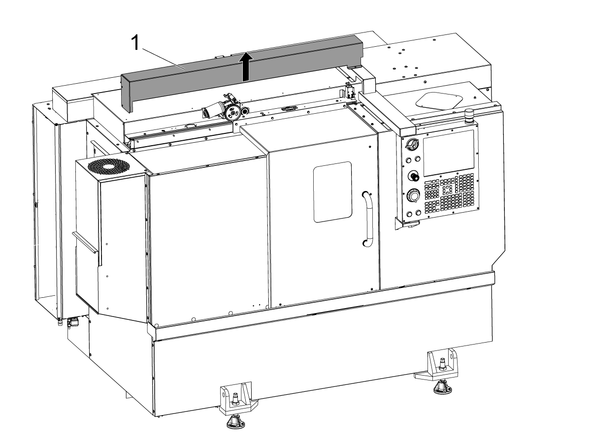
    Otomatik kapı kapağını çıkarın [1].

    2

    ST-20/25 ve DS-20Y/25Y:

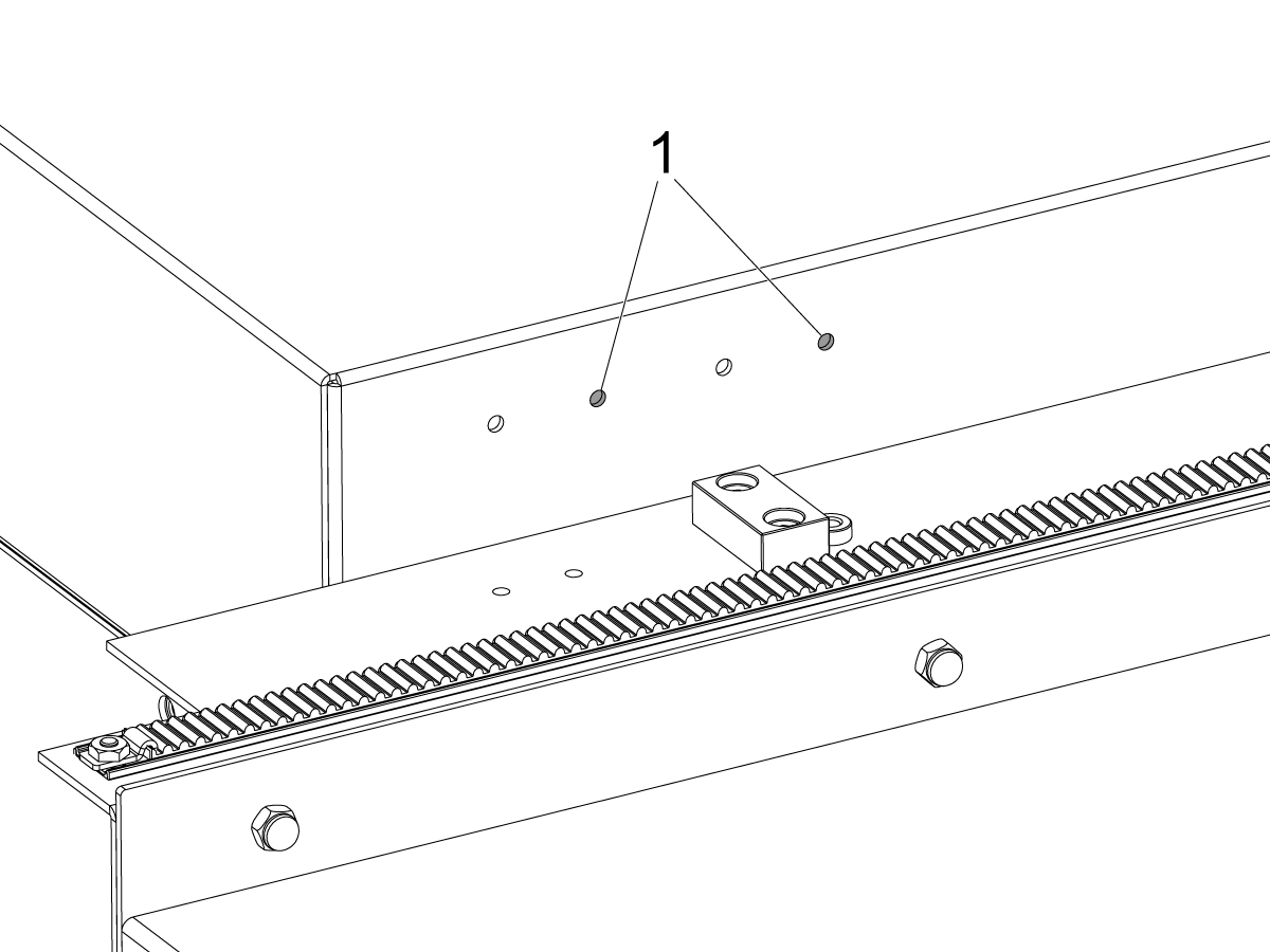
    Tavan panelinde anahtar braketi delikleri olan makineler için. Anahtar braketini ST-20/25 modellerinde sağdaki delik çiftine[1] takın.

    3

    Tavan panelinde anahtar braketi delikleri olmayan makineler için.

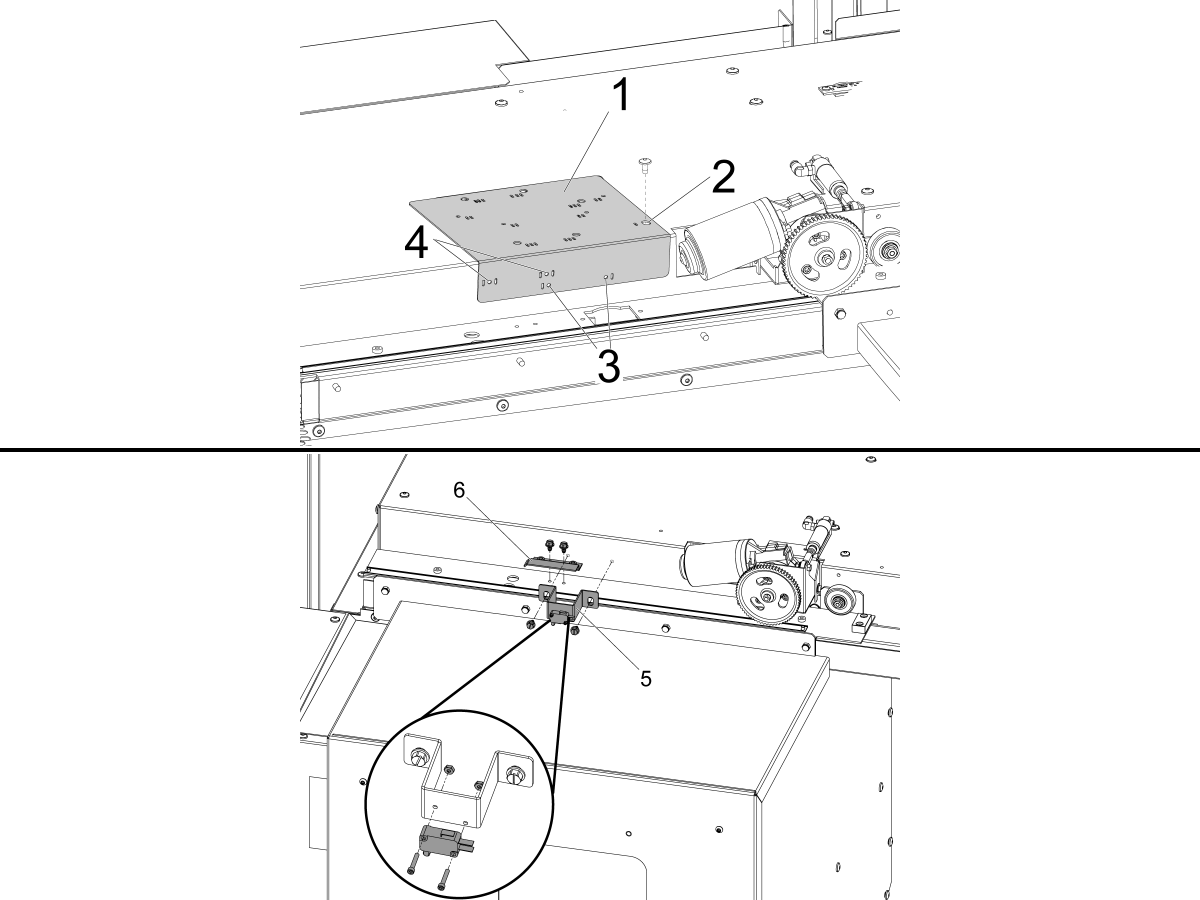
    Verilen matkap kılavuzunu [1] kullanarak DOOR FULLY OPEN durum anahtarı için montaj delikleri açın.

    Otomatik kapı motorunun solundaki otomatik kapı kapağı montaj deliği ile bir yuva [2] ile işaretlenmiş matkap kılavuzunun üstündeki en sağ deliği hizalayın ve BHCS ile sabitleyin.

    ST-10/15:

    • Bir kanal [3] ile işaretlenmiş delme kılavuz delikleri içinden iki  Ø 3/16" (4.7mm) bağlama deliği delin.

    ST-20/25 ve DS-20Y/25Y:

    • Her iki taraftaki iki kanal [4] ile işaretlenmiş delme kılavuz delikleri içinden iki  Ø 3/16" (4.7mm) bağlama deliği delin.

    Sağlanan kendinden dokunma vidalarını kullanarak, DOOR FULLY OPEN montajı [5] ve DOOR FULLY OPEN hata işareti [6].

    4

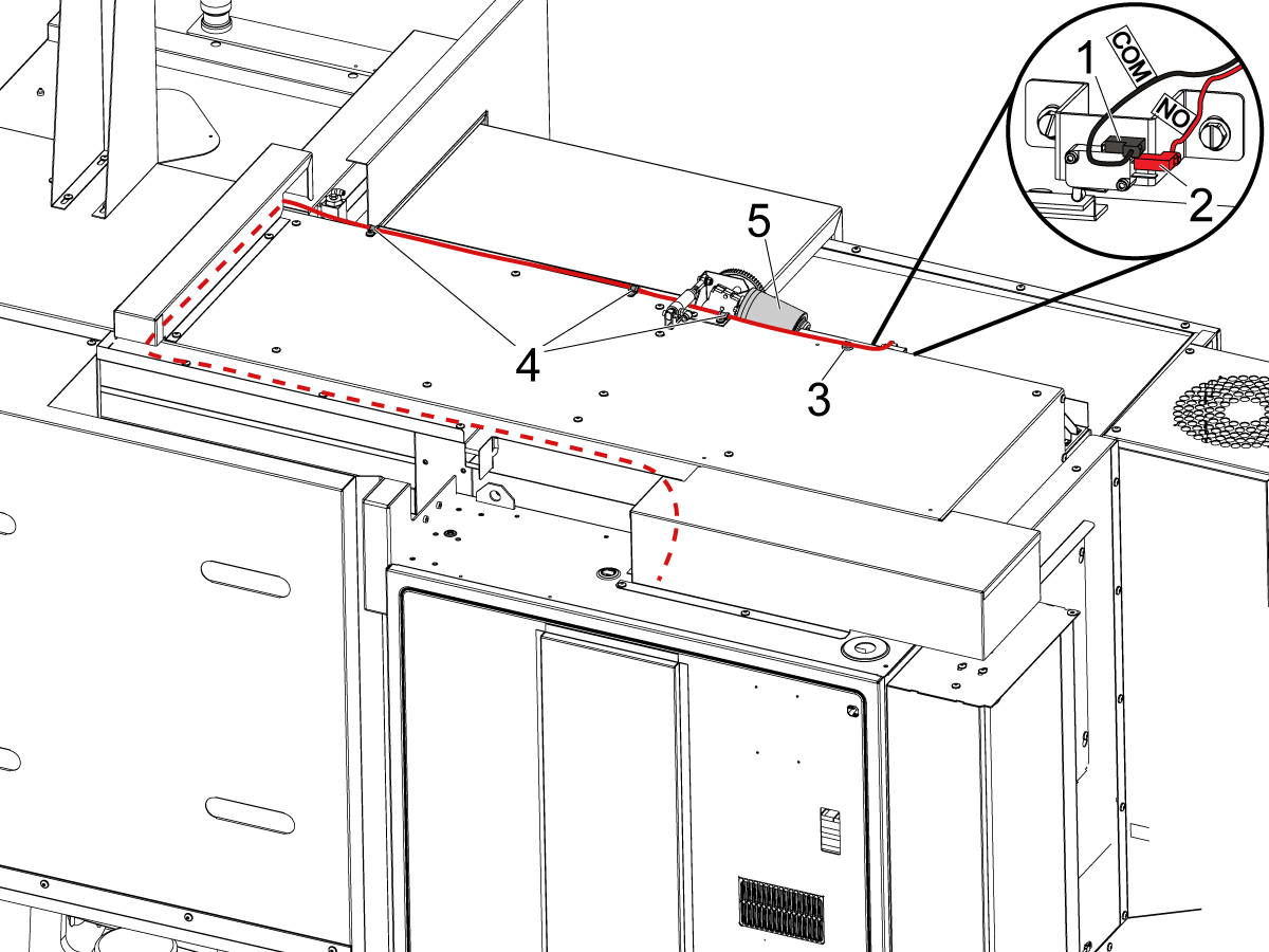
    KAPI TAMAMEN AÇIK anahtarını aşağıdaki etikete göre bağlayın:

    • Üst terminale [1] BLK <COM>.
    • KIRMIZI <NO> orta terminale [2].

    Kabloyu resimde gösterildiği gibi kontrol kabinine yönlendirin.

    Not: Kablonun hareketli otomatik kapı motorundan [5] uzakta kalmasını sağlamak için sağlanan manyetik klibi [3] ve Kablo kelepçelerini [4] taktığınızdan emin olun.

    5

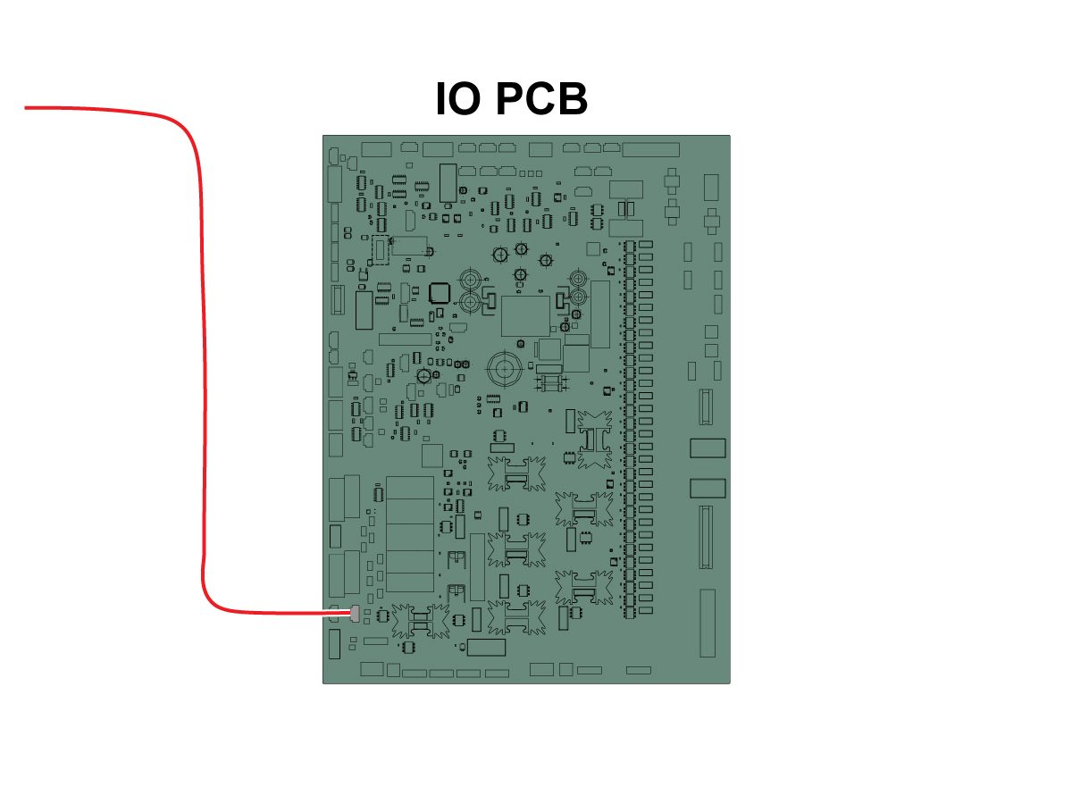
    Kablonun diğer ucunu SIO PCB P27 RRI Kapı Açık girişine bağlayın. 

    NOT: Makinenin KAPALI olduğundan emin olun.

    Autodoor kapağını takın.

    6

    • Yaylı itici ya 25mm veya 1" takım tutucu sığacak bir sapla yapılır
    • Bu takım taret üzerinde bir takım tutucu kaplamalıdır
    • Makine bir ST-10/15 ise kıskaç için yeterli alan sağlamak için iki boş takım tutucu gerekir
    • Parçanın aynaya düzgün bir biçimde oturmuş olduğundan emin olmak için herhangi bir programın başlangıcına aşağıdaki adımları programlayın:
      • Parçanın önündeki yay iticisini bulun
      • Yay'ı yaklaşık 0,50 inç veya 12,7 mm sıkıştırmak için Z eksenini hareket ettirin
      • Bir saniyelik bir süre ile aynayı açın.
      • Bir saniyelik bir süre ile chuaynayıck kapatın
      • Tareti mümkün olan en güvenli konuma geri çekin

    Not: Yay itici Parça Numarası: 

    • 30-12642 SPRING PUSHER.  25mm veya 1.0” tutucu ayrı satılır.

    Cobot Kurulumu

    1

    Cobot ve kontrol kutusunun eşleşen seri numaralarıyla aynı eşleşen setten olduğunu doğrulayın.

    Haas seri numarasının [1] yer aldığı bir çıkartma vardır. Bunların her iki kutuda da aynı olduğundan emin olun.

    Tanımlama numarası [2] olan sarı bir daire çıkartma vardır. Bunların her iki kutuda da aynı olduğundan emin olun.

    2

    Bu boyutları makinenin eteğinden kaidenin yan tarafına kadar ölçün.

     Not: Aşağıdaki boyutlar önerilen mesafelerdir. Pozisyon, kullanıcı uygulamasına bağlı olarak değişebilir. 

    Sonraki adımlardaki boyutları ön ve yan yükleme cobot’ları için referans olarak kullanın. 

    Haas Cobot 10’un Haas Cobot kaidesi ile eşleştirilmesi önerilir. Bu kaide, Haas tarafından tanımlanan parça boyutu ve ağırlık limitlerine göre kullanıldığında yeterince sabit olacak şekilde yapılandırılmıştır. 

    3

    ST-10 ve ST-15 Makineleri:

    Kaide ve parça tablasını makineye göre aşağıdaki konuma yerleştirin:

    Boyut İngiliz (İnç) Metrik (cm)
    Makinenin önünden kaidenin ön tarafına [1] 24,5 inç 62,2 cm
    Makinenin solundan kaidenin sol tarafına [2] 26,25 inç 66,7 cm
    Makinenin önünden parça tablasının ön tarafına [4] 5,5 inç 14 cm
    Makinenin solundan parça tablasının sol tarafına [4] 9,75 inç 24,7 cm

    4

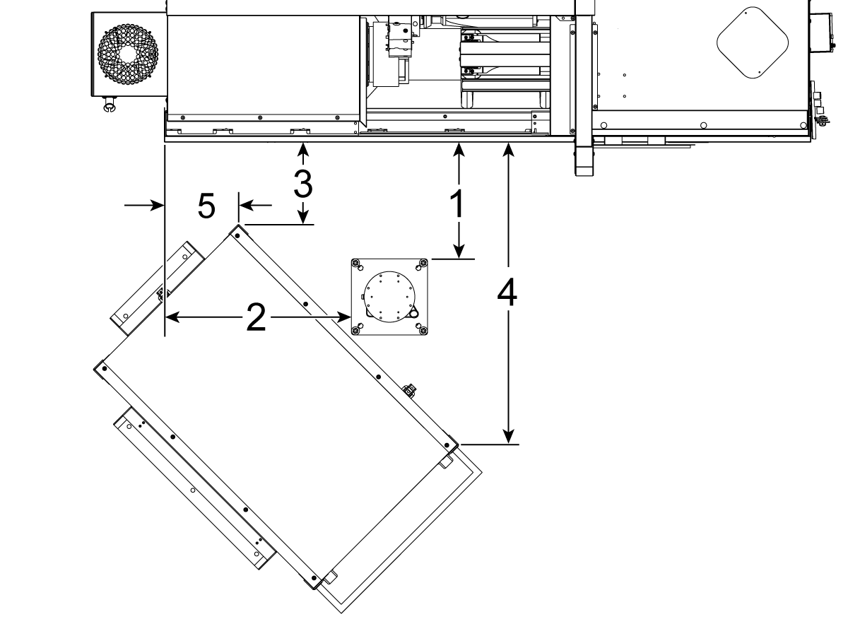
    Updated

    ST-20 ve ST-25 Makineleri ve DS-20Y/25Y:

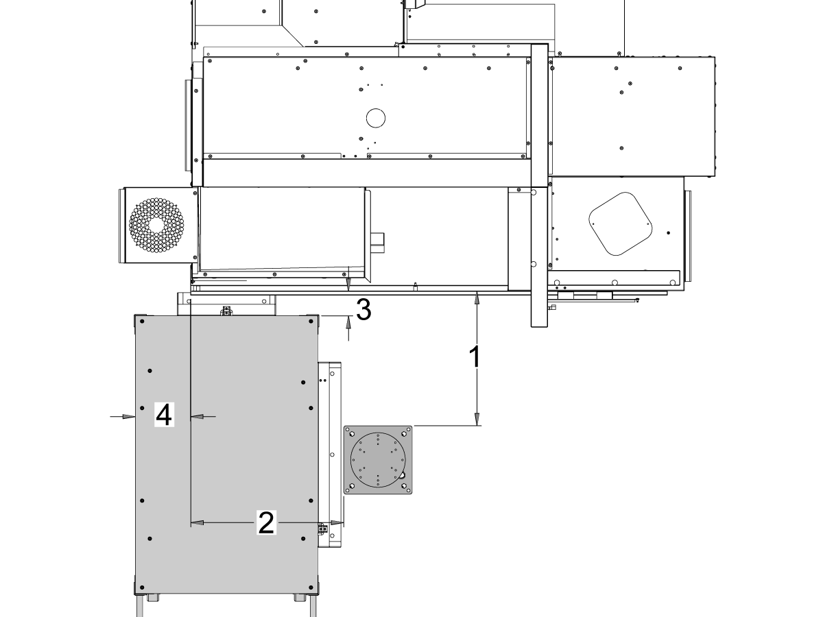
    Kaide ve parça tablasını makineye göre aşağıdaki konuma yerleştirin:

    Boyut İngiliz (İnç) Metrik (cm)
    Makinenin önünden kaidenin ön tarafına [1] 19,5 inç 49,5 cm
    Makinenin solundan kaidenin sol tarafına [2] 28,5 inç 72,4 cm
    Makinenin önünden parça tablasının sol ön köşesine [3] 14.5 inç 36,8 cm
    Makinenin önünden parça tablasının sağ ön köşesine [4] 71 inç 180 cm
    Makinenin solundan parça tablasının sol ön köşesine [5] 10,75 inç 27,3 cm

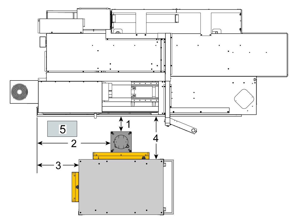
    5

    ST-30/35 ve DS-30Y Makineleri:

    Kaide, parça tablası ve Cobot Kontrol Kutusunu[5] makineye göre aşağıdaki konuma yerleştirin:

    Boyut İngiliz (İnç) Metrik (cm)
    Makinenin önünden kaidenin ön tarafına [1] 8,5 inç 21,6 cm
    Makinenin sol tarafından kaidenin sol tarafına [2] 42,0 inç 106,7 cm
    Makinenin sol tarafından parça tablasının sol tarafına [3] 23,5 inç 59,7 cm
    Makinenin önünden parça tablasının ön tarafına [4] 24,0 inç 61,0 cm

    6

    Kaideyi zemine sabitleyin. Su terazisini kullanarak tablayı tesviye edin. 

     NOT: Ayarlanabilir kaide için, ayar vidalarını [1] gevşeterek ve ardından çatal pimi [2] ayarlayarak istediğiniz yüksekliği ayarlayın. Robotu kurmadan önce ayar vidalarını [1] yeniden sıkın. Kaide üzerine bir su terazisi yerleştirin ve tabandaki (x4) altıgen cıvatayı kullanarak su terazisini X ve Y düzleminde ayarlayın.

    Kabloların yeterince gevşek olmasını sağlamak için Cobot kontrol kutusunu [3] doğrudan kaidenin yanına yerleştirin. 

    7

    Robotu taşıma kutusundan çıkarın. 

     Not: Gerekirse adaptör plakasını kaideyle robot arasına takın. 

    Cobot'u kaidenin üzerine takın.

     NOT: Cobot kablo konektörünün [1] makinenin ön tarafı ile aynı olduğundan emin olun. 

    ÖNEMLİ: Cobot yaklaşık 40lb'dir ve bu ağırlığı güvenli bir şekilde kaldırabilen bir cihazla kaldırılmalıdır.

    Robotu kurduktan sonra robot kaldırma donanımını çıkarın.

    8

    Cobot ambalajının içinde, aşağıdakiler de dahil olmak üzere yedek parçalarla doldurulmuş küçük bir torba [1] vardır: 

    • Sigorta
    • Vidalar (x2)
    • Kontrol Kutusu Anahtarları

    Ekstra M12 konektörüyle doldurulmuş orta boy bir torba [2] vardır. Bu kablo, Uç I/O Modülü için girişleri ve çıkışları yapılandırmak için kullanılabilir. 

    Kâğıtlarla doldurulmuş ve Cobot yazılımının indirilmiş olduğu bir USB bellek bulunan büyük bir çanta [3] vardır.

    Bu yedek parçaları ileride kullanmak üzere güvenli bir yerde sakladığınızdan emin olun. 

    Robot Electrical & Air - Installation

     DANGER: Working with the electrical services required for CNC machines is extremely hazardous and can result in serious injury or death.

    Before connecting line wires to the CNC:

    • Turn off all power to the machine at the source.
    • Perform a Lockout-Tagout (LOTO) procedure to ensure the power remains off during service.
    • Verify that power has been disconnected by using an AC voltage detector on all incoming lines.

    If you are uncertain about how to safely disconnect power or perform LOTO procedures:

    • Do not proceed.
    • Contact qualified personnel or obtain appropriate assistance before continuing.

    Failure to follow these precautions may result in electrical shock, equipment damage, or fatal injury.

     Danger: Before beginning any work inside the control cabinet, verify that the High Voltage indicator light on the 320V Power Supply / Vector Drive has been off for a minimum of five (5) minutes. This waiting period ensures that residual voltage has dissipated and reduces the risk of electric shock.

    Certain service procedures involve high-risk electrical components and may pose serious injury or fatality hazards. Technicians must not attempt any procedure unless they have a complete understanding of the steps involved and the associated risks.

    If there is any uncertainty regarding a procedure, contact your Haas Factory Outlet (HFO) to arrange for a qualified service technician.

    1

    Connect Interface Box to Haas Machine:

    The robot safety devices interface box 32-9018 has magnetic mounts to attach to the machine sheet metal. Mount the interface box [1] as shown in the picture.

    Route the interface electrical cables [2] along the enclosure with the magnetic mounts and zipties. Route the cable through the bottom of the electrical cabinet.

    NOTE: For information on upgrading the interface box to the Robot Safety Devices Interface Box, refer to the Robot Safety Devices Interface Box - Installation - AD0703. 

    2

    Connect Interface Box to Haas Control Cabinet:

    Connect cable 33-8562C E-STOP terminal block to TB-1B [1] and connect the Setup mode terminal block to TB-3B [1] on the SIO PCB.  

    Plug the user relay into K9 and K10 [2].

    Verify the jumper is installed on the SIO PCB at JP1.

    Connect the pigtail cable labeled P1 SIO to the SIO PCB at P1 [3]

    NOTE: If the machine has a Regen Vector Drive, unplug cable 33-0634 FILTER OV TO IOPCB P1 from P1 SIO and plug it into the connector FILTER OV FAULT on cable 33-8562C. If the machine does not have a Regen Vector Drive, do not plug anything into the connector FILTER OV FAULT.

    Connect the RJ-45 cable [4] to Ethernet to USB adapter [5] (33-0636).  Connect the USB connector end to the Maincon PCB J8 top port. Add a ferrite filter [6] to the USB adapter.

    Mount the 24VDC Power Supply [7] to the left side of the control cabinet and plug into connector labeled 24V PS on cable 33-8562C. Connect cable 33-1281 [8] to the 24VDC Power Supply [7] and plug into P3 on the PSUP PCB. 

    3

    For MM/SMM CM/CL machines Without XMR

    If P3 is occupied by a jumper connected from P3 [10] to P7 [9] on the PSUP PCB, a splitter cable is needed to allow the 24VDC power supply [7] to be connected to the 120VAC connectors on the PSUP. Connect the male connector of the splitter cable to P3 [10] and then connect the jumper from that cable to P7 [9] and also cable 33-1281 [8].

    Note: Make sure that the jumper cable is connected where the red lines up with the red from the splitter cable.

    4

    Inside the Cobot control box, install part of the robot signals cable (33-1272 or 33-1351).  To do so, remove the safety connector [1] from the Cobot control box in order to install the different colored wires into their respective location

    33-1272 / 33-1351 cables [2] going to safety connector:

    • Gray wire to top 24V
    • Red wire to bottom 24V
    • Green wire to EI0
    • Brown wire to EI1
    • Jumper [3] from SA0 to SA1
    • Jumper  [4] from SB0 to SB1

     NOTE: The rest of the wires from this cable are not used. Put some electrical tape on each wire lead and Ziptie the leftover unused wires. 

    5

    Important: After installing all the cables from the robot signal cable, make sure that the fuse [1] remains installed at all times to protect the Cobot control box.

    6

    Connect Cobot to the Interface Box:

    Connect the RJ45 ethernet cable [1] from the Cobot Control Box to the interface box. Add a ferrite filter [2] to the RJ-45 cable.

    Connect the robot signals cable [3] from the Cobot Control Box to the interface box. 

    Connect the 120 VAC Cobot Power Cable [4] to the external power source. 

    Connect the robot power cable [5] from the control box to the Cobot.

    Connect the teach pendant cable [6] from the control box to the teach pendant. 

    NOTE: For more information regarding interlock fence, area scanner or light curtain installation, refer to the Robot Safety Device section below.

    7

    Make sure the Remote Jog Handle is installed onto the machine.

    NOTE: For more information on the RJH-XL installation, refer to Remote Job Handle - Touch Large (RJH-XL) - Installation - AD0533. 

    8

    Steps 7 thru 10 are wiring and hose routing instructions for the pneumatic grippers. Refer to the grippers installation section lower on this page for the mechanical installation.

    Install the dual air solenoid assembly on to the side of the pedestal while giving the airlines enough slack. Make sure it's in a position where it will not be in the way. Route the airline [1] under the machine back towards the CALM cabinet as shown.

    9

    Inside the CALM cabinet, remove a plug from one of the CALM manifold ports and install the check valve [1] (58-1863) onto the port's fitting. Route the input airline [2] from the dual air solenoid assembly (from previous step) into the CALM cabinet and connect the airline to the check valve.

    Turn the machine air supply ON.

    10

    Make sure to power OFF the control box [1].

    Connect the solenoid cable from the dual air solenoid assembly [2] into the Digital Output on the Cobot control box [1]. Remove the connector from Cobot control box.

    11

    Connect the gripper solenoid power cable (33-1276 / 33-1341) to the Digital Output terminal inside the control box. Install the different colored wires into their respective location:

    • Black/white cable into 0V
    • Black cable into DO0
    • Orange/white cable into 0V
    • Orange cable into DO1
    • Red/white cable into 0V
    • Red cable into DO2
    • Brown/white cable into 0V
    • Brown cable into DO3

    Power ON the control box.

    Robot Güvenlik Cihazı

    ÖNEMLI: GÜVENLİK CİHAZININ ÇALIŞMASINI DOĞRU ŞEKİLDE YAPILANDIRIP TEST EDENE KADAR ROBOTU ÇALIŞTIRMAYIN.

    Işık Perdesi:

    Cobot paketleri, varsayılan güvenlik cihazı olarak ışık perdesi vericisi ve alıcısı ile birlikte verilir. Işık perdesi kurulumu için aşağıdaki prosedürü izleyin: 

    Işık Perdesi Kurulumu

    NOT: Alan tarayıcısı veya HC10 Makine Hazır kiti sipariş edilmişse, 1M ışık perdesi alıcısı ve vericisi de olacaktır. Bunlar tüm Cobot'larla birlikte verilir.

    Robot Siperi:

    Makine siper seçeneği ile donatılmış olarak geldiyse, robot siper ve kapı kilitleme tertibatının makineye takılması gerekir. Kurulum için aşağıdaki prosedürü izleyin:

    Robot Siperi Kurulumu

    Siper takıldıktan sonra, siper panelini makine ve robot siperi arasına takın.

    Alan Tarayıcısı:

    Makine alan tarayıcı seçeneğiyle donatılmış olarak geldiyse, alan tarayıcısının kurulması ve alana yapılandırılması gerekir. Kurulum için aşağıdaki prosedürü izleyin: 

    Alan Tarayıcı Kurulumu

    First Power-UP

    1

    Power ON the Haas machine. 

    Power ON the Cobot by flipping the power switch [1].

    Power ON the Cobot teach pendant by pressing the circle [2]. 

    Make sure that E-STOP [3] on the Cobot teach pendant is released. 

    In order to change the language, click on the language drop down menu. Choose EN for English. To confirm this setting change, the Cobot teach pendant will have a popup asking to insert the username & password. 

    Enter "admin" for both the username and password. 

    2

    Note: The Cobot teach pendant will have a popup asking to insert the username & password. To sign into the teach pendant use these credentials:

    • Username = admin
    • Password = admin

    Go into Run mode. Press Enable. 

    Go into Jog mode [1].

    Move each joint to it's zero location with the Move Zero buttons [2]. 

    3

    Once the robot is in it's zero location, verify that the hash lines [1] align on either side of each joint on the Cobot. 

     IMPORTANT: If any joint hash lines [1] do not align, jog the specific joint accordingly until all the hash lines [1] do align. This position will be set in the next step as the new Cobot zero position.  

    Connect an ethernet cable [2] from the Cobot control box into a computer.

    On the computer, change the adapter setting to enable the ethernet port. 

    Note: See next steps for help on changing adapter settings.

    4

    To change the adapter settings, open the settings page [1] on the computer, then click on Network & Internet [2] which will bring up the network status page.

    Click on Change adapter options [3] then right click on Ethernet [4] and open up the properties window [5]. From there select the Internet Protocol Version 4 (TCP/IPv4) [6] option and click Ok. 


    5

    The ethernet settings will now be correct. Open a web browser window and type in the IP address of the Cobot[1]. 

    Note: This is the same process as connecting a laptop to an HRP-1/2/3. For more information on connecting to the Cobot via ethernet, refer to the video on the HRP-Troubleshooting page that is in the Connect & Jog Haas Robot section. 

    6

    Download HRTool through HBC. On the Service section of HBC, navigate to Utilities > Documents and Software > 01 Control Software > 01 Next Generation Control > 10 Cobot Software > HRTool.zip.

    Unzip the folder and navigate to HRToolsMaind.exe.

    Insert the Cobot IP address found under the Systems tab.  Click Set. 

    Go to the Config tab on HRTool.

    Click "get" to see the actual vs. theoretical encoder values. 

    Click "set" to set the theoretical to the actual encoder values. This step sets the Cobot's current position as it's new home position. 

    7

    Make sure that each joint's actual and theoretical encoder values match. 

    NOTE: If the valuyes do not match, press "Set" again. 

    8

    On the teach pendant, navigate to System [1] and then Update System. 

    Confirm the Cobot firmware [2] is either:

    • HR5.51H.16.beta.20231213.zip
    • HR6.4.9.tmp.20240919.zip

    NOTE: Firmware version HR6.4.9.tmp.20240919.zip is compatible with all size cobots.

    Refer to the Haas Cobot - Maintenance chapter for the firmware update procedure. 

    9

    Turn on the Haas CNC.

    Zero Return all Axes.

    Insert Service USB key.  Go into Service mode.

    Go to Parameters> Factory tab.  Change the following:

    • 1278 [1278:] Robot Ready E-Stop Enabled to TRUE
    • 2191 [694:] LIGHT CUTAIN TYPE to LC_TYPE_1
    • 2194 [:] Enable Front Door Fully Open Switch to TRUE

    Note: Machines with Software Version 100.20.000.1010 or higher will need to change the following parameter:

    • 2192 [:] Light Curtain Trigger Threshold to 0

    Press [SETTING].

    Set the Settings:

    • 372 Parts Loader Type to 3: Robot.
    • 376 Light Curtain Enabled to On


    10

    On the Haas pendant, press [CURRENT COMMANDS].

    Go to Devices>Robot>Jogging tab. Change the following:

    • Maximum Jogging Speed to 7.9 inch/sec

     Note: The jogging increments on the RJH are a percentage of this max speed value. In order to decrease the distance the robot travels of each jog wheel tick, you need to change your Maximum Jogging Speed to a lower value.

    Go to the Setup tab. Change the following:

    • Max Robot Speed to 118 in/sec (2000 mm/sec). 
    • Enter the Net Mass of the gripper. Refer to the layout drawings on our website (Single Gripper layout drawing OR Dual Gripper layout drawing) to get the correct value for this setting
    WARNING: Setting this value incorrectly can cause the Robot Arm to not move correctly. 
     
    • Number of Grippers to the number of grippers.
    • Raw Gripper Clamp Output to 1.
    • Raw Gripper Unclamp Output to 2.
    • Raw Gripper Clamp Delay to the clamp/unclamp duration in sec.
    • Raw Gripper Clamp Type to OD/ID.
    • Finish Gripper Clamp Output to 3.
    • Finish Gripper Unclamp Output to 4.
    • Finish Gripper Clamp Delay to the clamp/unclamp duration in sec.
    • Raw Gripper Clamp Type to OD/ID.

    Security Risk Level

    1

    IMPORTANT: Make sure to perform an appropriate risk-assessment and met all appropriate safety requirements. 

    2

    Based off the risk assessment, set the appropriate security risk level on the Cobot teach pendant. Navigate to Config > General Restrictions and tap of the desired security risk level [1] from 0 - 5.

    Use the  "admin" code in the safety verification to change the security level.

    NOTE: When the security risk level is lower, the robot will have a lower maximum speed, force, etc. When the security risk level is higher, the robot will have a higher maximum speed, force, etc. 

    This security risk level will calculate the maximum allowable force, speed, power, momentum, elbow speed and elbow force [2] that the Cobot will withstand before Alarm 9150.10017 Collison Stop Error is triggered. 

    IMPORTANT: The robot's programmed speed cannot be greater than the allowable speed from the security risk level. 

    NOTE: For more information regarding alarms, refer to the Haas Cobot - Troubleshooting Guide. 

    Activation

    1

    Download and load the configuration files by logging into the HAAS SERVICE PORTAL.

    Download the safety automation option front/side configuration files.

    Load the option configuration patch file to the control. Refer to the NEXT GENERATION CONTROL - CONFIGURATION FILE - DOWNLOAD/LOAD procedure.

    2

    Go to Parameters > Features > Robot to verify that the robot feature has appeared on the bottom.

    3

    Press [CURRENT COMMANDS].

    Go to Devices>Robot>Setup tab [1].

    Press [E-Stop].

    Press [F1] to connect the robot[2].

    The first time connecting a robot to a machine, the robot feature will need to be unlocked. This popup shows the machine's current software version, robot mac address and a generated code. Enter this information into HBC in order to receive the unlock code.

    4

    On HBC, go to the Service tab [1].

    On the left hand side of the screen, click on Activations [2], and then select Cobot Installation [3] to begin the process to the get the Cobot unlock code.

    The first step is to enter the Machine Serial Number [4] and the Cobot Serial Number [5] in the fields on HBC.

    Once you have entered the correct information, press Next [6] in the bottom right corner and continue through the steps until you receive the unlock code.

    Note: Make sure you are on the Cobot Installation tab [3] and not the Robot Installation tab. The Robot Installation is only used for the Haas Robot Packages. Using the Robot Installation for the Haas Cobots will result in an invalid unlock code.

    5

    Enter the Cobot's Haas Serial Number[1] and the unlock code to connect the robot to the machine. 

     Note: This step can only be completed by a HFO Service Technician.

     Note: The machine needs to be activated before the Cobot is activated. Follow the Machine Activation / Time Extension - NGC procedure.

    When the robot has connected with the machine, a yellow message saying Robot Activation Successful should appear at the bottom of the Haas screen.

    6

    Release the [E-STOP] and press RESET to clear the alarms. 

    Press the [HANDLE JOG] button. 

    Press the [CURRENT COMMANDS]  and go to Devices > Robot > Jogging tab.

     Note: The robot in setup mode can only be handle jogged while the F2 button the RJH is pressed. See Setup/Run mode section below.

    On the Remote Handle Jog Touch press the Joint button to go into the Joints Coordinates.

    Move the robot to an accessible location to install the grippers.

    Jog J6 to 0.0000 position. The location hole should be centered on top.

    Note: Press [E-STOP] before working on the robot.

    Gripper Installation

    1

    Turn off the machine air by turning the valve in the Air/Lube cabinet and pull the pressure relief valve to release the air in the system.

    2

    For the Dual Action Gripper:

    There are two versions of the dual-action grippers for this section, both of which have the same installation process.

    Jog the robot so that the location hole [1] is centered on top.

    Install the adapter plate [2] onto the end of the robot arm.

    Install the dual gripper assembly [3] onto the adapter plate [2].

    NOTE: Make sure to install Gripper 1 (which has the orange and purple zip ties) onto the Gripper 1 adapter plate section. 

    3

    For the Angled Single Action Gripper:

    Jog the robot so that the location hole [1] should be centered on top.

    Install the angle adapter plate [2] to the end of the robot arm.

    Install the single gripper assembly [3] onto the angle adapter plate [2]. 

    4

    To install the bar gripper fingers, remove the slug gripper plates from the gripper bodies.

    Install the Bar Gripper Bolt Plates [3] with (x8) SHCS M6 screws [4]. Torque to 10 ft-lbs.

    Install the Bar Gripper Fingers [2] with (x8) SHCS 1/4-20 [1]. Torque to 13 ft-lbs.

    5

    Configure the dual air solenoid assembly used for pneumatic grippers depending on single [1] or dual [2] gripper configuration. 

    For single grippers [1], connect the incoming air to the to the fitting [2] and keep the plug in the other end of the fitting [3] as shown in the image.

    For dual grippers [4], remove the plug in the fitting [3] and attach a small air hose to the second solenoid [5]. Then connect the incoming air hose to the fitting [2] so that both solenoids are receiving air.

    6

    For the Single Gripper:

    Route the (x2) air lines from the gripper to the same color coded fitting on the dual air solenoid assembly. 

    Secure the air lines by wrapping them in cable conduit. Use the velcro straps to attach the cable conduit to the Cobot. Make sure there is enough slack so that cables aren't strained when Cobot is fully extended.

    Insert the input air hose to the used solenoid's fitting [1]. 

    Make sure the plug is installed onto the unused solenoid's fitting [2]. 

    7

    For the Dual Gripper:

    Route the (x2) air lines from gripper #1 to the same color coded fitting on the dual air solenoid assembly. 

    Route the (x2) air lines from gripper #2 to the same color coded fitting on the dual air solenoid assembly. 

    Secure the air lines by wrapping them in cable conduit. Use the velcro straps to attach the cable conduit to the Cobot. Make sure there is enough slack so that cables aren't strained when Cobot is fully extended.

    Insert the short airline [1] connecting the first solenoid with the second. 

    Insert the input air hose to the fitting [2]. 

    Parts Table Assembly

    If the parts table option was ordered, follow the procedure below for assembly instructions:

    Haas Robot - Parts Table Assembly

    NOTE: If HC10 MACHINE READY KIT was purchased, there is no need to install the wheels if mounting the parts table directly into the wooden pallet. 

    Verification

    Test the E-stop:

    • Press each E-STOP button located on the Haas Pendant, RJH-XL, and Cobot Teach Pendant. Make sure the machine generates 107 EMERGENCY STOP alarm.  If the E-STOP button does not generate a 107 EMERGENCY STOP alarm verify the wiring. Load the latest configuration files to enable the RJH-XL.

    Test the Robot Safety Device:

    Make sure that there is an E-STOP or light curtain triggered icon on the Haas pendant when the robot safety device is triggered. 

    • Fence - Insert the key into the interlock, verify that the two red LED lights in the front of the interlock are OFF. Remove the key from the interlock, verify that the two red LED lights are ON. 
    • Area Scanner - Step inside the protective field, verify that the red LED lights up on the area scanner. Step outside the protective field, verify that the green LED lights up.
    • Light Curtain - Interfere the light curtain beams, verify that the light curtain triggered icon appears on the Haas pendant. Press [RESET]. Step outside of the light curtain beams, verify no icon appears on the Haas pendant. 

    NOTE: If the light curtain triggered icon does not show, verify wiring, alignment and factory setting: 2191 [694:] LIGHT CURTAIN TYPE is set to LC_TYPE_1.

    Test the Operation of the Grippers:

    • Verify that both grippers clamp and unclamp correctly.
    • Press the [CURRENT COMMANDS]  and go to Devices > Robot > Jogging tab.
    • Press [F2] to clamp/unclamp the Finish Gripper.
    • Press [F3] to clamp/unclamp the Raw Gripper.

    Test the Remote Jog Handle:

    • Undock the Remote Jog Handle
    • Press the [HANDLE JOG] button. 
    • Press the [CURRENT COMMANDS]  and go to Devices > Robot > Jogging tab.
    • On the Remote Handle Jog press the Joint button to go into the Joints Coordinates.
    • Move the robot to a safe location.

    IMPORTANT: If a yellow warning message appears saying "Please activate Light Curtain or Cell Safe" while trying to job the robot, verify the safety parameter was applied by re-uploading the configuration files from HBC. 

    Verify Safe / Run Mode Operation

    All Haas CNC machines are equipped with a key switch on the side of the control pendant to lock and unlock setup mode. The robot will have the following behaviors depending on what mode is selected. 

    • When the Haas control is in Run mode, mode 1, triggering the robot safety device stops all motion. This motion can not be started until the robot safety device is no longer triggered.
    • When the Haas control is in Set up mode, mode 2, speed limited motion such as jogging an axis of the robot can be performed in order to program a robot's path of motion, pick up position, set a robot's tool center point, (an offset), load and pick up parts from the spindle or part holder in the machine, etc. The programmed path will also be able to be run slowly to prove out the programmed path of the robot. The robot in setup mode can only be handle jogged while the F2 button the RJH is pressed.

    Haas Robot - Hızlı Başlangıç Kılavuzu

    Robotu kurduktan sonra, aşağıdaki prosedürü izleyerek bir iş ayarlayın.

    Haas Robot - Hızlı Başlangıç Kılavuzu

    Robotu Devre Dışı Bırakma

    Makineyi bağımsız modda çalıştırmak amacıyla robotu devre dışı bırakmak için.

    SETTING düğmesine basın. Aşağıdaki Ayarları değiştirin:

    • 372 - Parça Yükleyici Türü, 0 olarak: YOK
    • 376 - Işık Perdesi Etkin, Kapalı
    • olarak


    5.3 DM/DT/MM/DC-1/UMC-350 Kurulumu

    Recently Updated

    Haas Cobot 10 (HC10) - DM/DT/MM/DC-1/UMC-350 - Kurulum


    AD0716

    Revizyon D - 11/2025

    Giriş

    Updated

    Bu prosedür size Haas 10KG Cobot’un (HC10) nasıl kurulduğunu gösterecektir.

    Not: Haas’ın CNC makinesi ve robottan oluşan tasarımlı çalışma hücresi, CE gerekliliklerine uygunluk açısından değerlendirilmiştir. Haas hücre tasarımındaki değişiklikler veya varyasyonlar, geçerli standartlara uygunluk açısından değerlendirilmelidir ve kullanıcının/entegre edenin sorumluluğundadır.

    Makine gereksinimleri:

    • 100.24.000.1001 sürümü veya üzeri
    • HR5.51H.16.beta.20231213.zip sürümü veya HR6.4.9.tmp20240919.zip sürümü.
    • DT/DM/MM/SMM/DC-1/UMC-350 Üretime Girme Tarihi: (her iki prosedürde de makine gerekliliklerine bakın)
      • Haas Otomatik Kapı
      • Haas Otomatik Pencere
        Not: MM/SMM, DM-3, DT-3 ve DC-1 sadece yan yükleme opsiyonu (93-1001053) için mevcuttur.
      • Not: Transformatörü olmayan MM/SMM makineleri, sahada kurulan cobotlar için sipariş edilmesi gereken bir ayırıcı kablosu gerektirecektir. Ayırıcı kablo 93-5067 olarak sipariş edilebilir.
    • 34-349xB I/O kartı veya üzeri
    • 93-1000610 UZAKTAN EL KUMANDASI DOKUNMATİK LCD (RJH-XL) UZAKTAN EL KUMANDASI - XL  

    Takım Gereksinimleri:

    • Mini Düz Kafa Tornavida

    Fixing / Anchoring Requirements

    • The Haas 10KG Cobot (HC10) is configured and sold by Haas with a pedestal/table that is sufficiently stable when used according to Haas defined part size and weight limits. 
    IMPORTANT:  For more information directly on the Hans Cobot, refer to the Hans Robot Operation Manual for Elfin Software.

    There are 3 scenarios in which the cobot option can be installed on a Haas machine:

    1. Cobot option was ordered at the same time as the machine. Both the cobot and the machine are being installed together.
    2. Cobot option is ordered so that it can be installed on a previously installed machine.
    3. Cobot option was previously installed on a machine, but will now be moved to a different Haas machine.

    In scenarios 2 and 3, additional parts will need to be ordered under the Serial Number of the Haas machine. See the tables below for what parts are needed in the different scenarios.

    Scenario 1 - Cobot and Machine are ordered and installed together

    Component Part Number Description
    NO ADDITIONAL PARTS NEED TO BE ORDERED WHEN COBOT AND MACHINE ARE ORDERED TOGETHER

    Scenario 2 - Cobot being field installed on existing Haas Machine

    Component Part Number Description
    CHECK TO SEE IF HAAS MACHINE ALREADY HAS THESE FEATURES & PARAMETERS BEFORE ORDERING
    Robot Feature Unlock Parameter 93-1001031 Kit activates the robot feature on the Haas machine. To check if you need this kit, go to the Features tab on the Haas Control and check if the Robot option is highlighted. This kit does not include any physical parts.
    Load Type Safety Parameters 93-1000997 Front Automation Safety Parameters - Kit is needed when the cobot will be loading parts through the front door of the Haas machine. This kit does not include any physical parts and the autodoor option would need to be purchased and installed separately.
    OR  
    93-1000996 Side Automation Safetly Parameters - Kit is needed when the cobot will be loading parts through the side window of the Haas machine. This kit does not include any physical parts and the autowindow option would need to be purchased and installed separately.

    Scenario 3 - Cobot is being transferred from one machine to a different Haas Machine

    Component Part Number Description
    Cobot Integration Kit See Integration Kit Compatibility Chart Kit is needed to install parts on the Haas machine to interface with the cobot. This includes the interface box, door switches, etc... as well as the Robot Unlock Feature parameter. This kit only needs to be purchased when transferring a cobot to a new Haas machine since these parts are normally included when a cobot is ordered. 
    Load Type Safety Parameters 93-1000997 Front Automation Safety Parameters - Kit is needed when the cobot will be loading parts through the front door of the Haas machine. This kit does not include any physical parts and the autodoor option would need to be purchased and installed separately.
    OR  
    93-1000996 Side Automation Safetly Parameters - Kit is needed when the cobot will be loading parts through the side window of the Haas machine. This kit does not include any physical parts and the autowindow option would need to be purchased and installed separately.
    Safety Device 08-1899 Multi-Sided Light Curtain Kit - Kit is needed if the safety device is NOT going to be transferred from the first machine and the second Haas machine needs it's own safety device. This kit makes a 4-sided protective barrier.
    OR  
    08-1948 5-Sided Light Curtain Kit - Kit is needed when the safety device is NOT going to be transferred from the first machine machine and the second Haas machine needs it's own safety device. This kit makes a 5-sided protective barrier.
    OR  
    08-1987 Laser Area Scanner Kit - Kit is needed when the safety device is NOT going to be transferred from the first machine machine and the second Haas machine needs it's own safety device. This area scanner has a sensing distance of 4meters.

    Makine Kurulumu

    1

    Önden Yüklemeli Robot:

    Yakınlık sensörü [2] için delme kılavuzunu [1] muhafazanın üstüne cıvatalayın.

    Muhafazanın yan tarafından 2x 10-32 delik delip kılavuz çekin.

    • Matkap boyutu: #21 veya 5/32"
    • 10-32 NF'ye dokunun

    Delme kılavuzunu [1] çıkarın. 

    Kapı açık proksimite anahtarını [2] muhafazanın yan tarafındaki bu deliklere takın.

    Kapıda istenen hareket bayrağı [3] konumunu bulmak için yakınlık sensörüne güç verin. Hareket bayrağı [3] proksimite sensörünü tetiklemek için iyi bir konuma geldiğinde, delik konumunu işaretleyin. 

    Hareket bayrağını [3] kendinden kılavuzlu vidalarla kapının yan tarafına takın. 

    Kapı tamamen açıkken kabloları resimde gösterildiği gibi kontrol kabinine yönlendirin.

    Yakınlık anahtarı kablosunu SIO PCB P27'ye bağlayın. 

    2

    Yandan Yüklemeli Robot:

    Otomatik Pencerenin hava silindirini [4] açığa çıkarmak için kapağı [1] ve donanımını [2] çıkarın. Hava silindirini [4], braketler [3] ve hava silindiri gösterildiği gibi takılacak şekilde yükseltin.

    Verilen gri ve sarı hava kanallarını Otomatik Pencere hava silindirine bağlayın; hava silindirindeki bağlantı noktalarında, her borunun nereye bağlandığını gösteren gri ve sarı kablo bağları olacaktır.

    Kapağı [2] Otomatik Pencerenin hava silindirine takın.

    3

    • Yaylı itici ya 25mm veya 1" takım tutucu sığacak bir sapla yapılır
    • Bu takım, takım karuselinde bir takım tutucuyu doldurmalıdır.
    • Parçanın mengeneye düzgün bir biçimde oturmuş olduğundan emin olmak için herhangi bir programın başlangıcına aşağıdaki adımları programlayın:
      • Parçanın üstündeki yay iticisini bulun
      • Yay'ı yaklaşık 0,50 inç veya 12,7 mm sıkıştırmak için Z eksenini hareket ettirin
      • Mengeneyi bir saniyeliğine açın.
      • Mengeneyi bir saniyeliğine kapatın

    Not: Yay itici Parça Numarası: 

    • 30-12642 SPRING PUSHER.  25mm veya 1.0” tutucu ayrı satılır.

    Cobot Kurulumu

    1

    Cobot ve kontrol kutusunun eşleşen seri numaralarıyla aynı eşleşen setten olduğunu doğrulayın.

    Haas seri numarasının [1] yer aldığı bir çıkartma vardır. Bunların her iki kutuda da aynı olduğundan emin olun.

    Tanımlama numarası [2] olan sarı bir daire çıkartma vardır. Bunların her iki kutuda da aynı olduğundan emin olun.

    2

    Bu boyutları makinenin eteğinden kaidenin yan tarafına kadar ölçün.

     Not: Aşağıdaki boyutlar önerilen mesafelerdir. Pozisyon, kullanıcı uygulamasına bağlı olarak değişebilir. Ön yükleme veya yan yükleme cobot’ları için cobot ve parça tablasında konumlandırma için sonraki adımlara bakın.

    Haas Cobot 10’un Haas Cobot kaidesi ile eşleştirilmesi önerilir. Bu kaide, Haas tarafından tanımlanan parça boyutu ve ağırlık limitlerine göre kullanıldığında yeterince sabit olacak şekilde yapılandırılmıştır. 

    3

    Önden Yükleme:

    Kaide ve parça tablasını makineye göre aşağıdaki konuma yerleştirin:

    Boyut İngiliz (İnç) Metrik (cm)
    Makinenin önünden kaidenin ön tarafına [1] 13 inç. 33 cm.
    Makinenin solundan kaidenin sol tarafına [2] 24 inç. 61 cm.
    Makinenin önünden parça tablasının sol ön köşesine [3] 8 inç. 20,3 cm.
    Makinenin önünden parça tablasının sağ ön köşesine [4] 42,25 inç. 107 cm.
    Makinenin solundan parça tablasının sol ön köşesine [5] 6,25 inç. 15,9 cm.

    4

    Yandan Yükleme:

    Kaide ve parça tablasını makineye göre aşağıdaki konuma yerleştirin:

    Boyut İngiliz (İnç) Metrik (cm)
    Makinenin önünden kaidenin sol tarafına [1] 21 inç. 53,4 cm.
    Makinenin sağından kaidenin ön tarafına [2] 13 inç. 33 cm.
    Makinenin önünden parça tablasının sol tarafına [3] 3 inç. 7,6 cm.
    Makinenin sağından parça tablasının ön tarafına [4] 27 inç. 68,6 cm.

    5

    Kaideyi zemine sabitleyin. Su terazisini kullanarak tablayı tesviye edin. 

    Ayar vidalarını [1] gevşeterek ve ardından çatal pimi [2] ayarlayarak istediğiniz yüksekliği ayarlayın. Robotu kurmadan önce ayar vidalarını [1] yeniden sıkın. Kaide üzerine bir su terazisi yerleştirin ve tabandaki (x4) altıgen cıvatayı kullanarak su terazisini X ve Y düzleminde ayarlayın.

    Kabloların yeterince gevşek olmasını sağlamak için Cobot kontrol kutusunu [3] doğrudan kaidenin yanına yerleştirin. 

    Not: Önceki adımlardaki düzenlerin kaide yüksekliği 61 cm'dir (24 inç).

    6

    Robotu taşıma kutusundan çıkarın. 

     Not: Gerekirse adaptör plakasını kaideyle robot arasına takın. 

    Cobot'u kaidenin üzerine takın.

     NOT: Cobot kablo konektörünün [1] makinenin ön tarafı ile aynı olduğundan emin olun. 

    ÖNEMLİ: Cobot yaklaşık 40lb'dir ve bu ağırlığı güvenli bir şekilde kaldırabilen bir cihazla kaldırılmalıdır.

    Robotu kurduktan sonra robot kaldırma donanımını çıkarın.

    7

    Cobot ambalajının içinde, aşağıdakiler de dahil olmak üzere yedek parçalarla doldurulmuş küçük bir torba [1] vardır: 

    • Sigorta
    • Vidalar (x2)
    • Kontrol Kutusu Anahtarları

    Ekstra M12 konektörüyle doldurulmuş orta boy bir torba [2] vardır. Bu kablo, Uç I/O Modülü için girişleri ve çıkışları yapılandırmak için kullanılabilir. 

    Kâğıtlarla doldurulmuş ve Cobot yazılımının indirilmiş olduğu bir USB bellek bulunan büyük bir çanta [3] vardır.

    Bu yedek parçaları ileride kullanmak üzere güvenli bir yerde sakladığınızdan emin olun. 

    Robot Electrical & Air - Installation

    1

    Connect Interface Box to Haas Machine:

    The robot safety devices interface box 32-9018 has magnetic mounts to attach to the machine sheet metal. Mount the interface box [1] as shown in the picture.

    Route the interface electrical cables [2] along the enclosure with the magnetic mounts and zipties. Route the cable through the bottom of the electrical cabinet.

    NOTE: For information on upgrading the interface box to the Robot Safety Devices Interface Box, refer to the Robot Safety Devices Interface Box - Installation - AD0703. 

    2

    Connect Interface Box to Haas Control Cabinet:

    Connect cable 33-8562C E-STOP terminal block to TB-1B [1] and connect the Setup mode terminal block to TB-3B [1] on the SIO PCB.  

    Plug the user relay into K9 and K10 [2].

    Verify the jumper is installed on the SIO PCB at JP1.

    Connect the pigtail cable labeled P1 SIO to the SIO PCB at P1 [3]

    NOTE: If the machine has a Regen Vector Drive, unplug cable 33-0634 FILTER OV TO IOPCB P1 from P1 SIO and plug it into the connector FILTER OV FAULT on cable 33-8562C. If the machine does not have a Regen Vector Drive, do not plug anything into the connector FILTER OV FAULT.

    Connect the RJ-45 cable [4] to Ethernet to USB adapter [5] (33-0636).  Connect the USB connector end to the Maincon PCB J8 top port. Add a ferrite filter [6] to the USB adapter.

    Mount the 24VDC Power Supply [7] to the left side of the control cabinet and plug into connector labeled 24V PS on cable 33-8562C. Connect cable 33-1281 [8] to the 24VDC Power Supply [7] and plug into P3 on the PSUP PCB. 

    3

    For MM/SMM CM/CL machines Without XMR

    If P3 is occupied by a jumper connected from P3 [10] to P7 [9] on the PSUP PCB, a splitter cable is needed to allow the 24VDC power supply [7] to be connected to the 120VAC connectors on the PSUP. Connect the male connector of the splitter cable to P3 [10] and then connect the jumper from that cable to P7 [9] and also cable 33-1281 [8].

    Note: Make sure that the jumper cable is connected where the red lines up with the red from the splitter cable.

    4

    Inside the Cobot control box, install part of the robot signals cable (33-1272 or 33-1351).  To do so, remove the safety connector [1] from the Cobot control box in order to install the different colored wires into their respective location

    33-1272 / 33-1351 cables [2] going to safety connector:

    • Gray wire to top 24V
    • Red wire to bottom 24V
    • Green wire to EI0
    • Brown wire to EI1
    • Jumper [3] from SA0 to SA1
    • Jumper  [4] from SB0 to SB1

     NOTE: The rest of the wires from this cable are not used. Put some electrical tape on each wire lead and Ziptie the leftover unused wires. 

    5

    Important: After installing all the cables from the robot signal cable, make sure that the fuse [1] remains installed at all times to protect the Cobot control box.

    6

    Connect Cobot to the Interface Box:

    Connect the RJ45 ethernet cable [1] from the Cobot Control Box to the interface box. Add a ferrite filter [2] to the RJ-45 cable.

    Connect the robot signals cable [3] from the Cobot Control Box to the interface box. 

    Connect the 120 VAC Cobot Power Cable [4] to the external power source. 

    Connect the robot power cable [5] from the control box to the Cobot.

    Connect the teach pendant cable [6] from the control box to the teach pendant. 

    NOTE: For more information regarding interlock fence, area scanner or light curtain installation, refer to the Robot Safety Device section below.

    7

    Make sure the Remote Jog Handle is installed onto the machine.

    NOTE: For more information on the RJH-XL installation, refer to Remote Job Handle - Touch Large (RJH-XL) - Installation - AD0533. 

    8

    Steps 7 thru 10 are wiring and hose routing instructions for the pneumatic grippers. Refer to the grippers installation section lower on this page for the mechanical installation.

    Install the dual air solenoid assembly on to the side of the pedestal while giving the airlines enough slack. Make sure it's in a position where it will not be in the way. Route the airline [1] under the machine back towards the CALM cabinet as shown.

    9

    Inside the CALM cabinet, remove a plug from one of the CALM manifold ports and install the check valve [1] (58-1863) onto the port's fitting. Route the input airline [2] from the dual air solenoid assembly (from previous step) into the CALM cabinet and connect the airline to the check valve.

    Turn the machine air supply ON.

    10

    Make sure to power OFF the control box [1].

    Connect the solenoid cable from the dual air solenoid assembly [2] into the Digital Output on the Cobot control box [1]. Remove the connector from Cobot control box.

    11

    Connect the gripper solenoid power cable (33-1276 / 33-1341) to the Digital Output terminal inside the control box. Install the different colored wires into their respective location:

    • Black/white cable into 0V
    • Black cable into DO0
    • Orange/white cable into 0V
    • Orange cable into DO1
    • Red/white cable into 0V
    • Red cable into DO2
    • Brown/white cable into 0V
    • Brown cable into DO3

    Power ON the control box.

    Robot Güvenlik Cihazı

    ÖNEMLI: GÜVENLİK CİHAZININ ÇALIŞMASINI DOĞRU ŞEKİLDE YAPILANDIRIP TEST EDENE KADAR ROBOTU ÇALIŞTIRMAYIN.

    Işık Perdesi:

    Cobot paketleri, varsayılan güvenlik cihazı olarak ışık perdesi vericisi ve alıcısı ile birlikte verilir. Işık perdesi kurulumu için aşağıdaki prosedürü izleyin: 

    Işık Perdesi Kurulumu

    NOT: Alan tarayıcısı veya HC10 Makine Hazır kiti sipariş edilmişse, 1M ışık perdesi alıcısı ve vericisi de olacaktır. Bunlar tüm Cobot'larla birlikte verilir.

    Robot Siperi:

    Makine siper seçeneği ile donatılmış olarak geldiyse, robot siper ve kapı kilitleme tertibatının makineye takılması gerekir. Kurulum için aşağıdaki prosedürü izleyin:

    Robot Siperi Kurulumu

    Siper kurulumu tamamlandıktan sonra, makine ile robot siperi arasına, önce makinenin üst kısmına takılan panelden başlayarak siper panelini takın.

    Not: Siperi makine muhafazasına bağlayan sac duvar panelleri, verilen kendinden kılavuz çekme vidalar kullanılarak bağlanmalı ve hiçbir delikle hizalanmamalıdır.

    Alan Tarayıcısı: 

    Makine alan tarayıcı seçeneğiyle donatılmış olarak geldiyse, alan tarayıcısının kurulması ve alana yapılandırılması gerekir. Kurulum için aşağıdaki prosedürü izleyin: 

    Alan Tarayıcı Kurulumu

    İlk güç-UP

    1

    HAAS makinesini ÇALIŞTIRIN. 

    Güç anahtarını [1] çevirerek Cobot'u AÇIN.

    Daireye [2] basarak Cobot öğretici asılı kumandasını AÇIN. 

    Öğretici asılı kumanda üzerindeki [E-STOP] [3] seçeneğinin serbest bırakıldığından emin olun. 

    Dili değiştirmek için dil açılır menüsüne tıklayın. İngilizce için EN seçeneğini belirleyin. Bu ayar değişikliğini onaylamak için Cobot öğretici asılı kumandada kullanıcı adı ve parolanın girilmesini isteyen bir açılır pencere olacaktır. 

    Hem kullanıcı adı hem de parola için "admin" girin. 

    2

    Not: Cobot öğretici asılı kumandada kullanıcı adı ve parolanın girilmesini isteyen bir açılır pencere olacaktır. Öğretici asılı kumandada oturum açmak için şu kimlik bilgilerini kullanın:

    • Kullanıcı adı = admin
    • Parola = admin

    Çalıştırma moduna geçin. Etkinleştir'e basın. 

    Elle Kumanda moduna [1] gidin.

    Her bağlantyı Sıfırı Taşı düğmeleri [2] ile sıfır konumuna taşıyın. 

    3

    Robot sıfır konumuna geldiğinde, karma çizgilerinin [1] Cobot üzerindeki her bağlantının her iki tarafında da hizalandığını doğrulayın. 

     ÖNEMLİ: Herhangi bir bağlantı karma hattı [1] hizalanmazsa, tüm karma hatları [1] hizalanana kadar buna göre elle kumanda edin. Bu konum, bir sonraki adımda yeni Cobot sıfır konumu olarak ayarlanacaktır.  

    Cobot kontrol kutusundan bir bilgisayara bir ethernet kablosu [2] bağlayın.

    Bilgisayarda, ethernet portunu etkinleştirmek için adaptör ayarını değiştirin. 

    Not: Adaptör ayarlarını değiştirme konusunda yardım için sonraki adımlara bakın.

    4

    Adaptör ayarlarını değiştirmek için, bilgisayardaki ayarlar sayfasını [1] açın, ardından ağ durumu sayfasını açacak olan Ağ ve İnternet [2] üzerine tıklayın.

    Adaptör seçeneklerini değiştir [3] üzerine tıklayın, sonra Ethernet [4] üzerine sağ tıklayın ve özellikler penceresini açın [5]. Buradan İnternet Protokolü Sürüm 4 (TCP/IPv4) [6] seçeneğini seçin ve Tamam'a tıklayın. 


    5

    Ethernet ayarları artık doğru olacaktır. Bir web tarayıcısı penceresi açın ve Cobot'un IP adresini yazın [1]. 

    Not: Bu, bir dizüstü bilgisayarı HRP-1/2/3'e bağlamakla aynı süreçtir. Cobota ethernet üzerinden bağlanma hakkında daha fazla bilgi için, Haas Robota Bağlan ve Elle Kumanda Et bölümündeki HRP-Sorun Giderme  sayfasındaki videoya bakın. 

    6

    HRTool’u HBC üzerinden indirin. HBC Servis bölümünde Yardımcı Programlar > Belgeler ve Yazılım > 01 Kontrol Yazılımı > 01 Yeni Nesil Kontrol > 10 Cobot Yazılımı > HRTool.zip.

    Klasörü açın ve HRToolsMaind.exe dosyasına gidin.

    Sistemler sekmesi altında bulunan Cobot IP adresini girin.  Ayarla’ya tıklayın. 

    HRTool üzerindeki Yapılandırma sekmesine gidin.

    Gerçek ve teorik enkoder değerlerini görmek için "al" seçeneğine tıklayın. 

    Teorik olan enkoder değerini gerçek olarak ayarlamak için "ayarla" seçeneğine tıklayın. Bu adım, Cobot'un o andaki konumunu yeni başlangıç konumu olarak ayarlar. 

    7

    Her bağlantının gerçek ve teorik enkoder değerlerinin eşleştiğinden emin olun. 

    NOT: Değerler eşleşmiyorsa, tekrar "Ayarla" seçeneğine basın. 

    8

    Öğretici asılı kumandada, Sistem’e [1], ardından da Sistemi Güncelle'ye gidin. 

    Cobot aygıt yazılımının [2] aşağıdakilerden biri olduğunu onaylayın:

    • HR5.51H.16.beta.20231213.zip
    • HR6.4.9.tmp.20240919.zip

    NOT: Aygıt yazılımı sürümü HR6.4.9.tmp.20240919.zip, tüm boyuttan cobotlara uyumludur.

    Aygıt yazılımı güncelleme prosedürü için bkz. Haas Cobot - Bakım bölümü. 

    9

    Haas CNC'yi açın.

    Tüm Eksenleri Referansa Döndür.

    Servis USB anahtarını takın.  Servis moduna gidin.

    Parametreler> Fabrika sekmesine gidin.  Aşağıdakileri değiştirin:

    • 1278 [1278:] Robot Hazır E-Stop TRUE olarak Etkinleştirildi
    • 2191 [694:] IŞIK PERDESİ TİPİ, LC_TYPE_1
    • olarak
    • 2194 [:] Ön Kapı Tam Açık Anahtarını Etkinleştir, DOĞRU olarak

    Not: 100.20.000.1010 veya daha yüksek Yazılım Sürümlü Makinelerde aşağıdaki parametrenin değiştirilmesi gerekecektir:

    • 2192 [:] Işık Perdesi Tetik Eşiği , 0
    • olarak

    SETTING (Ayar) düğmesine basın.

    Ayarları Yapın:

    • 372 - Parça Yükleyici Türü, 3 olarak: Robot.
    • 376 - Işık Perdesi Etkin, Açık
    • olarak ayarlandı


    10

    Haas asılı kumandada [CURRENT COMMANDS] tuşuna basın.

    Cihazlar>Robot>Elle Kumanda  sekmesine gidin. Aşağıdakileri değiştirin:

    • Maximum Jogging Speed (Maksimum Elle Kumanda Hızı) 7,9  inç/sn
    • olarak

     Not: RJH'deki elle kumanda artışları bu maksimum hız değerinin bir yüzdesidir. Robotun her elle kumanda tekerleği tıklamasıyla hareketini azaltmak için Maksimum Elle Kumanda Hızını daha düşük bir değer olarak değiştirmeniz gerekir.

    Kurulum sekmesine gidin. Aşağıdakileri değiştirin:

    • Maksimum Robot Hızı 118 inç/sn  (2000 mm/sn). 
    • Kıskacın Net Kütlesini girin. Bu ayar için doğru değeri almak üzere web sitemizdeki yerleşim çizimlerine (Tek Kıskaç yerleşim çizimi VEYA Çift Kıskaç yerleşim çizimi) bakın
    UYARI: Bu değerin yanlış ayarlanması Robot Kolunun doğru hareket etmemesine neden olabilir. 
     
    • Kıskaç Sayısı kıskaç sayısına göre.
    • Ham Malzeme Kıskacı Klamp Çıkışı 1 olarak.
    • Ham Malzeme Kıskacı Klamp Açma Çıkışı, 2 olarak.
    • Ham Malzeme Kıskacı Klamp Gecikmesi klamp/ayırma süresi sn olarak.
    • Ham Malzeme Kıskacı Klamp Tipi  OD/İD olarak.
    • Finiş Kıskacı Klamp Çıkışı, 3 olarak.
    • Finiş Kıskacı Klamp Açma Çıkışı, 4olarak.
    • Finiş Kıskacı Gecikmesi klamp/klamp açma süresi sn olarak.
    • Ham Malzeme Kıskacı Klamp Tipi  OD/İD olarak.

    Security Risk Level

    1

    IMPORTANT: Make sure to perform an appropriate risk-assessment and met all appropriate safety requirements. 

    2

    Based off the risk assessment, set the appropriate security risk level on the Cobot teach pendant. Navigate to Config > General Restrictions and tap of the desired security risk level [1] from 0 - 5.

    Use the  "admin" code in the safety verification to change the security level.

    NOTE: When the security risk level is lower, the robot will have a lower maximum speed, force, etc. When the security risk level is higher, the robot will have a higher maximum speed, force, etc. 

    This security risk level will calculate the maximum allowable force, speed, power, momentum, elbow speed and elbow force [2] that the Cobot will withstand before Alarm 9150.10017 Collison Stop Error is triggered. 

    IMPORTANT: The robot's programmed speed cannot be greater than the allowable speed from the security risk level. 

    NOTE: For more information regarding alarms, refer to the Haas Cobot - Troubleshooting Guide. 

    Activation

    1

    Download and load the configuration files by logging into the HAAS SERVICE PORTAL.

    Download the safety automation option front/side configuration files.

    Load the option configuration patch file to the control. Refer to the NEXT GENERATION CONTROL - CONFIGURATION FILE - DOWNLOAD/LOAD procedure.

    2

    Go to Parameters > Features > Robot to verify that the robot feature has appeared on the bottom.

    3

    Press [CURRENT COMMANDS].

    Go to Devices>Robot>Setup tab [1].

    Press [E-Stop].

    Press [F1] to connect the robot[2].

    The first time connecting a robot to a machine, the robot feature will need to be unlocked. This popup shows the machine's current software version, robot mac address and a generated code. Enter this information into HBC in order to receive the unlock code.

    4

    On HBC, go to the Service tab [1].

    On the left hand side of the screen, click on Activations [2], and then select Cobot Installation [3] to begin the process to the get the Cobot unlock code.

    The first step is to enter the Machine Serial Number [4] and the Cobot Serial Number [5] in the fields on HBC.

    Once you have entered the correct information, press Next [6] in the bottom right corner and continue through the steps until you receive the unlock code.

    Note: Make sure you are on the Cobot Installation tab [3] and not the Robot Installation tab. The Robot Installation is only used for the Haas Robot Packages. Using the Robot Installation for the Haas Cobots will result in an invalid unlock code.

    5

    Enter the Cobot's Haas Serial Number[1] and the unlock code to connect the robot to the machine. 

     Note: This step can only be completed by a HFO Service Technician.

     Note: The machine needs to be activated before the Cobot is activated. Follow the Machine Activation / Time Extension - NGC procedure.

    When the robot has connected with the machine, a yellow message saying Robot Activation Successful should appear at the bottom of the Haas screen.

    6

    Release the [E-STOP] and press RESET to clear the alarms. 

    Press the [HANDLE JOG] button. 

    Press the [CURRENT COMMANDS]  and go to Devices > Robot > Jogging tab.

     Note: The robot in setup mode can only be handle jogged while the F2 button the RJH is pressed. See Setup/Run mode section below.

    On the Remote Handle Jog Touch press the Joint button to go into the Joints Coordinates.

    Move the robot to an accessible location to install the grippers.

    Jog J6 to 0.0000 position. The location hole should be centered on top.

    Note: Press [E-STOP] before working on the robot.

    Gripper Installation

    1

    Turn off the machine air by turning the valve in the Air/Lube cabinet and pull the pressure relief valve to release the air in the system.

    2

    For the Dual Action Gripper:

    There are two versions of the dual-action grippers for this section, both of which have the same installation process.

    Jog the robot so that the location hole [1] is centered on top.

    Install the adapter plate [2] onto the end of the robot arm.

    Install the dual gripper assembly [3] onto the adapter plate [2].

    NOTE: Make sure to install Gripper 1 (which has the orange and purple zip ties) onto the Gripper 1 adapter plate section. 

    3

    For the Angled Single Action Gripper:

    Jog the robot so that the location hole [1] should be centered on top.

    Install the angle adapter plate [2] to the end of the robot arm.

    Install the single gripper assembly [3] onto the angle adapter plate [2]. 

    4

    To install the bar gripper fingers, remove the slug gripper plates from the gripper bodies.

    Install the Bar Gripper Bolt Plates [3] with (x8) SHCS M6 screws [4]. Torque to 10 ft-lbs.

    Install the Bar Gripper Fingers [2] with (x8) SHCS 1/4-20 [1]. Torque to 13 ft-lbs.

    5

    Configure the dual air solenoid assembly used for pneumatic grippers depending on single [1] or dual [2] gripper configuration. 

    For single grippers [1], connect the incoming air to the to the fitting [2] and keep the plug in the other end of the fitting [3] as shown in the image.

    For dual grippers [4], remove the plug in the fitting [3] and attach a small air hose to the second solenoid [5]. Then connect the incoming air hose to the fitting [2] so that both solenoids are receiving air.

    6

    For the Single Gripper:

    Route the (x2) air lines from the gripper to the same color coded fitting on the dual air solenoid assembly. 

    Secure the air lines by wrapping them in cable conduit. Use the velcro straps to attach the cable conduit to the Cobot. Make sure there is enough slack so that cables aren't strained when Cobot is fully extended.

    Insert the input air hose to the used solenoid's fitting [1]. 

    Make sure the plug is installed onto the unused solenoid's fitting [2]. 

    7

    For the Dual Gripper:

    Route the (x2) air lines from gripper #1 to the same color coded fitting on the dual air solenoid assembly. 

    Route the (x2) air lines from gripper #2 to the same color coded fitting on the dual air solenoid assembly. 

    Secure the air lines by wrapping them in cable conduit. Use the velcro straps to attach the cable conduit to the Cobot. Make sure there is enough slack so that cables aren't strained when Cobot is fully extended.

    Insert the short airline [1] connecting the first solenoid with the second. 

    Insert the input air hose to the fitting [2]. 

    Parts Table Assembly

    If the parts table option was ordered, follow the procedure below for assembly instructions:

    Haas Robot - Parts Table Assembly

    NOTE: If HC10 MACHINE READY KIT was purchased, there is no need to install the wheels if mounting the parts table directly into the wooden pallet. 

    Verification

    Test the E-stop:

    • Press each E-STOP button located on the Haas Pendant, RJH-XL, and Cobot Teach Pendant. Make sure the machine generates 107 EMERGENCY STOP alarm.  If the E-STOP button does not generate a 107 EMERGENCY STOP alarm verify the wiring. Load the latest configuration files to enable the RJH-XL.

    Test the Robot Safety Device:

    Make sure that there is an E-STOP or light curtain triggered icon on the Haas pendant when the robot safety device is triggered. 

    • Fence - Insert the key into the interlock, verify that the two red LED lights in the front of the interlock are OFF. Remove the key from the interlock, verify that the two red LED lights are ON. 
    • Area Scanner - Step inside the protective field, verify that the red LED lights up on the area scanner. Step outside the protective field, verify that the green LED lights up.
    • Light Curtain - Interfere the light curtain beams, verify that the light curtain triggered icon appears on the Haas pendant. Press [RESET]. Step outside of the light curtain beams, verify no icon appears on the Haas pendant. 

    NOTE: If the light curtain triggered icon does not show, verify wiring, alignment and factory setting: 2191 [694:] LIGHT CURTAIN TYPE is set to LC_TYPE_1.

    Test the Operation of the Grippers:

    • Verify that both grippers clamp and unclamp correctly.
    • Press the [CURRENT COMMANDS]  and go to Devices > Robot > Jogging tab.
    • Press [F2] to clamp/unclamp the Finish Gripper.
    • Press [F3] to clamp/unclamp the Raw Gripper.

    Test the Remote Jog Handle:

    • Undock the Remote Jog Handle
    • Press the [HANDLE JOG] button. 
    • Press the [CURRENT COMMANDS]  and go to Devices > Robot > Jogging tab.
    • On the Remote Handle Jog press the Joint button to go into the Joints Coordinates.
    • Move the robot to a safe location.

    IMPORTANT: If a yellow warning message appears saying "Please activate Light Curtain or Cell Safe" while trying to job the robot, verify the safety parameter was applied by re-uploading the configuration files from HBC. 

    Verify Safe / Run Mode Operation

    All Haas CNC machines are equipped with a key switch on the side of the control pendant to lock and unlock setup mode. The robot will have the following behaviors depending on what mode is selected. 

    • When the Haas control is in Run mode, mode 1, triggering the robot safety device stops all motion. This motion can not be started until the robot safety device is no longer triggered.
    • When the Haas control is in Set up mode, mode 2, speed limited motion such as jogging an axis of the robot can be performed in order to program a robot's path of motion, pick up position, set a robot's tool center point, (an offset), load and pick up parts from the spindle or part holder in the machine, etc. The programmed path will also be able to be run slowly to prove out the programmed path of the robot. The robot in setup mode can only be handle jogged while the F2 button the RJH is pressed.

    Haas Robot - Hızlı Başlangıç Kılavuzu

    Robotu kurduktan sonra, aşağıdaki prosedürü izleyerek bir iş ayarlayın.

    Haas Robot - Hızlı Başlangıç Kılavuzu

    Robotu Devre Dışı Bırakma

    Makineyi bağımsız modda çalıştırmak amacıyla robotu devre dışı bırakmak için.

    SETTING düğmesine basın. Aşağıdaki Ayarları değiştirin:

    • 372 - Parça Yükleyici Türü , 0 olarak: YOK
    • 376 Işık Perdesi Etkin, Kapalı olarak ayarlandı

    5.4 UMC-400/500 Kurulumu

    Recently Updated

    Haas Cobot 10 (HC10) - UMC-400/500 - Kurulum


    AD0717

    Revizyon D - 11/2025

    Giriş

    Bu prosedür size Haas 10KG Cobot (HC10) Kol Paketinin UMC’nize nasıl kurulacağını gösterecektir.

    Not: Haas’ın CNC makinesi ve robottan oluşan tasarımlı çalışma hücresi, CE gerekliliklerine uygunluk açısından değerlendirilmiştir. Haas hücre tasarımındaki değişiklikler veya varyasyonlar, geçerli standartlara uygunluk açısından değerlendirilmelidir ve kullanıcının/entegre edenin sorumluluğundadır.

    Updated

    Makine gereksinimleri:

    • UMC-500/SS Üretime Girme Tarihi: 18.03.2022 90 Derece Kontrol Kabini ve Haas İş Parçası Bağlama Hazır
    • 90 Derece Kontrol Kabinine ve Haas İş Parçası Bağlamaya Hazıra sahip
    • UMC-400/SS (SADECE YAN YÜKLEME)
    • Haas Otomatik Kapı veya Otomatik Pencere
    • 100.24.000.1001 sürümü veya üzeri
    • HR5.51H.16.beta.20231213.zip sürümü veya HR6.4.9.tmp20240919.zip sürümü.
    • 34-349xB I/O kartı veya üzeri
    • 93-1000610 UZAKTAN EL KUMANDASI DOKUN LCD (RJH-XL) UZAKTAN EL KUMANDASI - XL

    Takım Gereksinimleri:

    • Mini Düz Kafa Tornavida

    Fixing / Anchoring Requirements

    • The Haas 10KG Cobot (HC10) is configured and sold by Haas with a pedestal/table that is sufficiently stable when used according to Haas defined part size and weight limits. 
    IMPORTANT:  For more information directly on the Hans Cobot, refer to the Hans Robot Operation Manual for Elfin Software.

    There are 3 scenarios in which the cobot option can be installed on a Haas machine:

    1. Cobot option was ordered at the same time as the machine. Both the cobot and the machine are being installed together.
    2. Cobot option is ordered so that it can be installed on a previously installed machine.
    3. Cobot option was previously installed on a machine, but will now be moved to a different Haas machine.

    In scenarios 2 and 3, additional parts will need to be ordered under the Serial Number of the Haas machine. See the tables below for what parts are needed in the different scenarios.

    Scenario 1 - Cobot and Machine are ordered and installed together

    Component Part Number Description
    NO ADDITIONAL PARTS NEED TO BE ORDERED WHEN COBOT AND MACHINE ARE ORDERED TOGETHER

    Scenario 2 - Cobot being field installed on existing Haas Machine

    Component Part Number Description
    CHECK TO SEE IF HAAS MACHINE ALREADY HAS THESE FEATURES & PARAMETERS BEFORE ORDERING
    Robot Feature Unlock Parameter 93-1001031 Kit activates the robot feature on the Haas machine. To check if you need this kit, go to the Features tab on the Haas Control and check if the Robot option is highlighted. This kit does not include any physical parts.
    Load Type Safety Parameters 93-1000997 Front Automation Safety Parameters - Kit is needed when the cobot will be loading parts through the front door of the Haas machine. This kit does not include any physical parts and the autodoor option would need to be purchased and installed separately.
    OR  
    93-1000996 Side Automation Safetly Parameters - Kit is needed when the cobot will be loading parts through the side window of the Haas machine. This kit does not include any physical parts and the autowindow option would need to be purchased and installed separately.

    Scenario 3 - Cobot is being transferred from one machine to a different Haas Machine

    Component Part Number Description
    Cobot Integration Kit See Integration Kit Compatibility Chart Kit is needed to install parts on the Haas machine to interface with the cobot. This includes the interface box, door switches, etc... as well as the Robot Unlock Feature parameter. This kit only needs to be purchased when transferring a cobot to a new Haas machine since these parts are normally included when a cobot is ordered. 
    Load Type Safety Parameters 93-1000997 Front Automation Safety Parameters - Kit is needed when the cobot will be loading parts through the front door of the Haas machine. This kit does not include any physical parts and the autodoor option would need to be purchased and installed separately.
    OR  
    93-1000996 Side Automation Safetly Parameters - Kit is needed when the cobot will be loading parts through the side window of the Haas machine. This kit does not include any physical parts and the autowindow option would need to be purchased and installed separately.
    Safety Device 08-1899 Multi-Sided Light Curtain Kit - Kit is needed if the safety device is NOT going to be transferred from the first machine and the second Haas machine needs it's own safety device. This kit makes a 4-sided protective barrier.
    OR  
    08-1948 5-Sided Light Curtain Kit - Kit is needed when the safety device is NOT going to be transferred from the first machine machine and the second Haas machine needs it's own safety device. This kit makes a 5-sided protective barrier.
    OR  
    08-1987 Laser Area Scanner Kit - Kit is needed when the safety device is NOT going to be transferred from the first machine machine and the second Haas machine needs it's own safety device. This area scanner has a sensing distance of 4meters.

    Makine Kurulumu

    1

    Önden Yüklemeli Robot: 

    Otomatik kapı motor kapağını çıkarın. 

    Yeni yakınlık anahtarı braketini [1] motorun altındaki makineye takın.

    Yakınlık anahtarı açma bayrağını [2] yakınlık anahtarı braketinin [1] üstüne takın. 

    Yakınlık anahtarı braketini [3] varolan yakınlık anahtarı bloğuna bağlayın [1]. 

    Kapıyı normalde açık (NO) yakınlık anahtarını [4] yakınlık anahtarı yuvasına [3] takın.

    Otomatik kapı motor kapağını takın. 

    Kapı normalde açıkken (NO) kabloları resimde gösterildiği gibi kontrol kabinine yönlendirin.

    Yakınlık anahtarı kablosunu SIO PCB P27'ye bağlayın. 

    2

    • Yaylı itici ya 25mm veya 1" takım tutucu sığacak bir sapla yapılır
    • Bu takım, takım karuselinde bir takım tutucuyu doldurmalıdır.
    • Parçanın mengeneye düzgün bir biçimde oturmuş olduğundan emin olmak için herhangi bir programın başlangıcına aşağıdaki adımları programlayın:
      • Parçanın üstündeki yay iticisini bulun
      • Yay'ı yaklaşık 0,50 inç veya 12,7 mm sıkıştırmak için Z eksenini hareket ettirin
      • Mengeneyi bir saniyeliğine açın.
      • Mengeneyi bir saniyeliğine kapatın

    Not: Yay itici Parça Numarası: 

    • 30-12642 SPRING PUSHER.  25mm veya 1.0” tutucu ayrı satılır.

    Cobot Kurulumu

    1

    Cobot ve kontrol kutusunun eşleşen seri numaralarıyla aynı eşleşen setten olduğunu doğrulayın.

    Haas seri numarasının [1] yer aldığı bir çıkartma vardır. Bunların her iki kutuda da aynı olduğundan emin olun.

    Tanımlama numarası [2] olan sarı bir daire çıkartma vardır. Bunların her iki kutuda da aynı olduğundan emin olun.

    2

    Bu boyutları makinenin eteğinden kaidenin yan tarafına kadar ölçün.

     Not: Aşağıdaki boyutlar önerilen mesafelerdir. Pozisyon, kullanıcı uygulamasına bağlı olarak değişebilir. Ön yükleme veya yan yükleme cobot’ları için cobot ve parça tablasında konumlandırma için sonraki adımlara bakın.

    Haas Cobot 10’un Haas Cobot kaidesi ile eşleştirilmesi önerilir. Bu kaide, Haas tarafından tanımlanan parça boyutu ve ağırlık limitlerine göre kullanıldığında yeterince sabit olacak şekilde yapılandırılmıştır. 

    3

    Önden Yükleme:

    Kaide ve parça tablasını makineye göre aşağıdaki konuma yerleştirin:

    Boyut İngiliz (İnç) Metrik (cm)
    Makinenin önünden kaidenin ön tarafına [1] 9,5 inç. 24 cm.
    Makinenin solundan kaidenin sol tarafına [2] 38 inç. 96,5 cm.
    Makinenin önünden parça tablasının sol ön köşesine [3] 4,5 inç. 11,5 cm.
    Makinenin önünden parça tablasının sol arka köşesine [4] 27 inç. 68,5 cm.
    Makinenin solundan parça tablasının sol ön köşesine [5] 21 inç. 53 cm.

    4

    Yandan Yükleme:

    Kaide ve parça tablasını makineye göre aşağıdaki konuma yerleştirin:

    Boyut UMC-400 UMC-500
    Makinenin önünden kaidenin sol tarafına [1] 14,5 inç (36,8 cm.) 17,5 inç (44,5 cm.)
    Makinenin sağından kaidenin ön tarafına [2] 4,5 inç (11,4 cm.) 5 inç (12,5 cm.)
    Makinenin önünden parça tablasının sol tarafına [3] 3 inç (7,62 cm.) 0 inç (0 cm.)
    Makinenin sağından parça tablasının ön tarafına [4] 23,5 inç (59,7 cm.) 24 inç (61 cm.)

    5

    Kaideyi zemine sabitleyin. Su terazisini kullanarak tablayı tesviye edin. 

     NOT: Ayarlanabilir kaide için, ayar vidalarını [1] gevşeterek ve ardından çatal pimi [2] ayarlayarak istediğiniz yüksekliği ayarlayın. Robotu kurmadan önce ayar vidalarını [1] yeniden sıkın. Kaide üzerine bir su terazisi yerleştirin ve tabandaki (x4) altıgen cıvatayı kullanarak su terazisini X ve Y düzleminde ayarlayın.

    Kabloların yeterince gevşek olmasını sağlamak için Cobot kontrol kutusunu [3] doğrudan kaidenin yanına yerleştirin. 

    6

    Robotu taşıma kutusundan çıkarın. 

     Not: Gerekirse adaptör plakasını kaideyle robot arasına takın. 

    Cobot'u kaidenin üzerine takın.

     NOT: Cobot kablo konektörünün [1] makinenin ön tarafı ile aynı olduğundan emin olun. 

    ÖNEMLİ: Cobot yaklaşık 40lb'dir ve bu ağırlığı güvenli bir şekilde kaldırabilen bir cihazla kaldırılmalıdır.

    Robotu kurduktan sonra robot kaldırma donanımını çıkarın.

    7

    Cobot ambalajının içinde, aşağıdakiler de dahil olmak üzere yedek parçalarla doldurulmuş küçük bir torba [1] vardır: 

    • Sigorta
    • Vidalar (x2)
    • Kontrol Kutusu Anahtarları

    Ekstra M12 konektörüyle doldurulmuş orta boy bir torba [2] vardır. Bu kablo, Uç I/O Modülü için girişleri ve çıkışları yapılandırmak için kullanılabilir. 

    Kâğıtlarla doldurulmuş ve Cobot yazılımının indirilmiş olduğu bir USB bellek bulunan büyük bir çanta [3] vardır.

    Bu yedek parçaları ileride kullanmak üzere güvenli bir yerde sakladığınızdan emin olun. 

    Robot Electrical & Air - Installation

    1

    Connect Interface Box to Haas Machine:

    The robot safety devices interface box 32-9018 has magnetic mounts to attach to the machine sheet metal. Mount the interface box [1] as shown in the picture.

    Route the interface electrical cables [2] along the enclosure with the magnetic mounts and zipties. Route the cable through the bottom of the electrical cabinet.

    NOTE: For information on upgrading the interface box to the Robot Safety Devices Interface Box, refer to the Robot Safety Devices Interface Box - Installation - AD0703. 

    2

    Connect Interface Box to Haas Control Cabinet:

    Connect cable 33-8562C E-STOP terminal block to TB-1B [1] and connect the Setup mode terminal block to TB-3B [1] on the SIO PCB.  

    Plug the user relay into K9 and K10 [2].

    Verify the jumper is installed on the SIO PCB at JP1.

    Connect the pigtail cable labeled P1 SIO to the SIO PCB at P1 [3]

    NOTE: If the machine has a Regen Vector Drive, unplug cable 33-0634 FILTER OV TO IOPCB P1 from P1 SIO and plug it into the connector FILTER OV FAULT on cable 33-8562C. If the machine does not have a Regen Vector Drive, do not plug anything into the connector FILTER OV FAULT.

    Connect the RJ-45 cable [4] to Ethernet to USB adapter [5] (33-0636).  Connect the USB connector end to the Maincon PCB J8 top port. Add a ferrite filter [6] to the USB adapter.

    Mount the 24VDC Power Supply [7] to the left side of the control cabinet and plug into connector labeled 24V PS on cable 33-8562C. Connect cable 33-1281 [8] to the 24VDC Power Supply [7] and plug into P3 on the PSUP PCB. 

    3

    For MM/SMM CM/CL machines Without XMR

    If P3 is occupied by a jumper connected from P3 [10] to P7 [9] on the PSUP PCB, a splitter cable is needed to allow the 24VDC power supply [7] to be connected to the 120VAC connectors on the PSUP. Connect the male connector of the splitter cable to P3 [10] and then connect the jumper from that cable to P7 [9] and also cable 33-1281 [8].

    Note: Make sure that the jumper cable is connected where the red lines up with the red from the splitter cable.

    4

    Inside the Cobot control box, install part of the robot signals cable (33-1272 or 33-1351).  To do so, remove the safety connector [1] from the Cobot control box in order to install the different colored wires into their respective location

    33-1272 / 33-1351 cables [2] going to safety connector:

    • Gray wire to top 24V
    • Red wire to bottom 24V
    • Green wire to EI0
    • Brown wire to EI1
    • Jumper [3] from SA0 to SA1
    • Jumper  [4] from SB0 to SB1

     NOTE: The rest of the wires from this cable are not used. Put some electrical tape on each wire lead and Ziptie the leftover unused wires. 

    5

    Important: After installing all the cables from the robot signal cable, make sure that the fuse [1] remains installed at all times to protect the Cobot control box.

    6

    Connect Cobot to the Interface Box:

    Connect the RJ45 ethernet cable [1] from the Cobot Control Box to the interface box. Add a ferrite filter [2] to the RJ-45 cable.

    Connect the robot signals cable [3] from the Cobot Control Box to the interface box. 

    Connect the 120 VAC Cobot Power Cable [4] to the external power source. 

    Connect the robot power cable [5] from the control box to the Cobot.

    Connect the teach pendant cable [6] from the control box to the teach pendant. 

    NOTE: For more information regarding interlock fence, area scanner or light curtain installation, refer to the Robot Safety Device section below.

    7

    Make sure the Remote Jog Handle is installed onto the machine.

    NOTE: For more information on the RJH-XL installation, refer to Remote Job Handle - Touch Large (RJH-XL) - Installation - AD0533. 

    8

    Steps 7 thru 10 are wiring and hose routing instructions for the pneumatic grippers. Refer to the grippers installation section lower on this page for the mechanical installation.

    Install the dual air solenoid assembly on to the side of the pedestal while giving the airlines enough slack. Make sure it's in a position where it will not be in the way. Route the airline [1] under the machine back towards the CALM cabinet as shown.

    9

    Inside the CALM cabinet, remove a plug from one of the CALM manifold ports and install the check valve [1] (58-1863) onto the port's fitting. Route the input airline [2] from the dual air solenoid assembly (from previous step) into the CALM cabinet and connect the airline to the check valve.

    Turn the machine air supply ON.

    10

    Make sure to power OFF the control box [1].

    Connect the solenoid cable from the dual air solenoid assembly [2] into the Digital Output on the Cobot control box [1]. Remove the connector from Cobot control box.

    11

    Connect the gripper solenoid power cable (33-1276 / 33-1341) to the Digital Output terminal inside the control box. Install the different colored wires into their respective location:

    • Black/white cable into 0V
    • Black cable into DO0
    • Orange/white cable into 0V
    • Orange cable into DO1
    • Red/white cable into 0V
    • Red cable into DO2
    • Brown/white cable into 0V
    • Brown cable into DO3

    Power ON the control box.

    Robot Safety Device

    IMPORTANT: DO NOT OPERATE THE ROBOT UNTIL YOU HAVE PROPERLY CONFIGURED AND TESTED THE OPERATION OF THE SAFETY DEVICE.

    Light Curtain:

    Cobot packages come with the light curtain emitter and receiver as the default safety device. Follow the procedure below for light curtain installation: 

    Light Curtain Installation

    NOTE: If the area scanner or HC10 Machine Ready kit was ordered, there will also be a 1M light curtain receiver and emitter. These come with all Cobots. 

    Robot Fence:

    If the machine came equipped with the fence option, the robot fence and door interlock assembly need to be installed to machine. Follow the procedure below for installation:

    Robot Fence Installation

    Once the fence is installed, next install the fence panel in between the machine and robot fence starting with the panel that gets attached to the top of the machine first.

    Note: The sheet metal wall panels that connect the fence to the machine enclosure will need to be installed using the provided self-tapping screws and will not line up with any holes.

    Area Scanner: 

    If the machine came equipped with the area scanner option, the area scanner needs to be installed and configured to the space. Follow the procedure below for installation: 

    Area Scanner Installation

    First Power-UP

    1

    Power ON the Haas machine. 

    Power ON the Cobot by flipping the power switch [1].

    Power ON the Cobot teach pendant by pressing the circle [2]. 

    Make sure that E-STOP [3] on the Cobot teach pendant is released. 

    In order to change the language, click on the language drop down menu. Choose EN for English. To confirm this setting change, the Cobot teach pendant will have a popup asking to insert the username & password. 

    Enter "admin" for both the username and password. 

    2

    Note: The Cobot teach pendant will have a popup asking to insert the username & password. To sign into the teach pendant use these credentials:

    • Username = admin
    • Password = admin

    Go into Run mode. Press Enable. 

    Go into Jog mode [1].

    Move each joint to it's zero location with the Move Zero buttons [2]. 

    3

    Once the robot is in it's zero location, verify that the hash lines [1] align on either side of each joint on the Cobot. 

     IMPORTANT: If any joint hash lines [1] do not align, jog the specific joint accordingly until all the hash lines [1] do align. This position will be set in the next step as the new Cobot zero position.  

    Connect an ethernet cable [2] from the Cobot control box into a computer.

    On the computer, change the adapter setting to enable the ethernet port. 

    Note: See next steps for help on changing adapter settings.

    4

    To change the adapter settings, open the settings page [1] on the computer, then click on Network & Internet [2] which will bring up the network status page.

    Click on Change adapter options [3] then right click on Ethernet [4] and open up the properties window [5]. From there select the Internet Protocol Version 4 (TCP/IPv4) [6] option and click Ok. 


    5

    The ethernet settings will now be correct. Open a web browser window and type in the IP address of the Cobot[1]. 

    Note: This is the same process as connecting a laptop to an HRP-1/2/3. For more information on connecting to the Cobot via ethernet, refer to the video on the HRP-Troubleshooting page that is in the Connect & Jog Haas Robot section. 

    6

    Download HRTool through HBC. On the Service section of HBC, navigate to Utilities > Documents and Software > 01 Control Software > 01 Next Generation Control > 10 Cobot Software > HRTool.zip.

    Unzip the folder and navigate to HRToolsMaind.exe.

    Insert the Cobot IP address found under the Systems tab.  Click Set. 

    Go to the Config tab on HRTool.

    Click "get" to see the actual vs. theoretical encoder values. 

    Click "set" to set the theoretical to the actual encoder values. This step sets the Cobot's current position as it's new home position. 

    7

    Make sure that each joint's actual and theoretical encoder values match. 

    NOTE: If the valuyes do not match, press "Set" again. 

    8

    On the teach pendant, navigate to System [1] and then Update System. 

    Confirm the Cobot firmware [2] is either:

    • HR5.51H.16.beta.20231213.zip
    • HR6.4.9.tmp.20240919.zip

    NOTE: Firmware version HR6.4.9.tmp.20240919.zip is compatible with all size cobots.

    Refer to the Haas Cobot - Maintenance chapter for the firmware update procedure. 

    9

    Turn on the Haas CNC.

    Zero Return all Axes.

    Insert Service USB key.  Go into Service mode.

    Go to Parameters> Factory tab.  Change the following:

    • 1278 [1278:] Robot Ready E-Stop Enabled to TRUE
    • 2191 [694:] LIGHT CUTAIN TYPE to LC_TYPE_1
    • 2194 [:] Enable Front Door Fully Open Switch to TRUE

    Note: Machines with Software Version 100.20.000.1010 or higher will need to change the following parameter:

    • 2192 [:] Light Curtain Trigger Threshold to 0

    Press [SETTING].

    Set the Settings:

    • 372 Parts Loader Type to 3: Robot.
    • 376 Light Curtain Enabled to On


    10

    On the Haas pendant, press [CURRENT COMMANDS].

    Go to Devices>Robot>Jogging tab. Change the following:

    • Maximum Jogging Speed to 7.9 inch/sec

     Note: The jogging increments on the RJH are a percentage of this max speed value. In order to decrease the distance the robot travels of each jog wheel tick, you need to change your Maximum Jogging Speed to a lower value.

    Go to the Setup tab. Change the following:

    • Max Robot Speed to 118 in/sec (2000 mm/sec). 
    • Enter the Net Mass of the gripper. Refer to the layout drawings on our website (Single Gripper layout drawing OR Dual Gripper layout drawing) to get the correct value for this setting
    WARNING: Setting this value incorrectly can cause the Robot Arm to not move correctly. 
     
    • Number of Grippers to the number of grippers.
    • Raw Gripper Clamp Output to 1.
    • Raw Gripper Unclamp Output to 2.
    • Raw Gripper Clamp Delay to the clamp/unclamp duration in sec.
    • Raw Gripper Clamp Type to OD/ID.
    • Finish Gripper Clamp Output to 3.
    • Finish Gripper Unclamp Output to 4.
    • Finish Gripper Clamp Delay to the clamp/unclamp duration in sec.
    • Raw Gripper Clamp Type to OD/ID.

    Security Risk Level

    1

    IMPORTANT: Make sure to perform an appropriate risk-assessment and met all appropriate safety requirements. 

    2

    Based off the risk assessment, set the appropriate security risk level on the Cobot teach pendant. Navigate to Config > General Restrictions and tap of the desired security risk level [1] from 0 - 5.

    Use the  "admin" code in the safety verification to change the security level.

    NOTE: When the security risk level is lower, the robot will have a lower maximum speed, force, etc. When the security risk level is higher, the robot will have a higher maximum speed, force, etc. 

    This security risk level will calculate the maximum allowable force, speed, power, momentum, elbow speed and elbow force [2] that the Cobot will withstand before Alarm 9150.10017 Collison Stop Error is triggered. 

    IMPORTANT: The robot's programmed speed cannot be greater than the allowable speed from the security risk level. 

    NOTE: For more information regarding alarms, refer to the Haas Cobot - Troubleshooting Guide. 

    Activation

    1

    Download and load the configuration files by logging into the HAAS SERVICE PORTAL.

    Download the safety automation option front/side configuration files.

    Load the option configuration patch file to the control. Refer to the NEXT GENERATION CONTROL - CONFIGURATION FILE - DOWNLOAD/LOAD procedure.

    2

    Go to Parameters > Features > Robot to verify that the robot feature has appeared on the bottom.

    3

    Press [CURRENT COMMANDS].

    Go to Devices>Robot>Setup tab [1].

    Press [E-Stop].

    Press [F1] to connect the robot[2].

    The first time connecting a robot to a machine, the robot feature will need to be unlocked. This popup shows the machine's current software version, robot mac address and a generated code. Enter this information into HBC in order to receive the unlock code.

    4

    On HBC, go to the Service tab [1].

    On the left hand side of the screen, click on Activations [2], and then select Cobot Installation [3] to begin the process to the get the Cobot unlock code.

    The first step is to enter the Machine Serial Number [4] and the Cobot Serial Number [5] in the fields on HBC.

    Once you have entered the correct information, press Next [6] in the bottom right corner and continue through the steps until you receive the unlock code.

    Note: Make sure you are on the Cobot Installation tab [3] and not the Robot Installation tab. The Robot Installation is only used for the Haas Robot Packages. Using the Robot Installation for the Haas Cobots will result in an invalid unlock code.

    5

    Enter the Cobot's Haas Serial Number[1] and the unlock code to connect the robot to the machine. 

     Note: This step can only be completed by a HFO Service Technician.

     Note: The machine needs to be activated before the Cobot is activated. Follow the Machine Activation / Time Extension - NGC procedure.

    When the robot has connected with the machine, a yellow message saying Robot Activation Successful should appear at the bottom of the Haas screen.

    6

    Release the [E-STOP] and press RESET to clear the alarms. 

    Press the [HANDLE JOG] button. 

    Press the [CURRENT COMMANDS]  and go to Devices > Robot > Jogging tab.

     Note: The robot in setup mode can only be handle jogged while the F2 button the RJH is pressed. See Setup/Run mode section below.

    On the Remote Handle Jog Touch press the Joint button to go into the Joints Coordinates.

    Move the robot to an accessible location to install the grippers.

    Jog J6 to 0.0000 position. The location hole should be centered on top.

    Note: Press [E-STOP] before working on the robot.

    Gripper Installation

    1

    Turn off the machine air by turning the valve in the Air/Lube cabinet and pull the pressure relief valve to release the air in the system.

    2

    For the Dual Action Gripper:

    There are two versions of the dual-action grippers for this section, both of which have the same installation process.

    Jog the robot so that the location hole [1] is centered on top.

    Install the adapter plate [2] onto the end of the robot arm.

    Install the dual gripper assembly [3] onto the adapter plate [2].

    NOTE: Make sure to install Gripper 1 (which has the orange and purple zip ties) onto the Gripper 1 adapter plate section. 

    3

    For the Angled Single Action Gripper:

    Jog the robot so that the location hole [1] should be centered on top.

    Install the angle adapter plate [2] to the end of the robot arm.

    Install the single gripper assembly [3] onto the angle adapter plate [2]. 

    4

    To install the bar gripper fingers, remove the slug gripper plates from the gripper bodies.

    Install the Bar Gripper Bolt Plates [3] with (x8) SHCS M6 screws [4]. Torque to 10 ft-lbs.

    Install the Bar Gripper Fingers [2] with (x8) SHCS 1/4-20 [1]. Torque to 13 ft-lbs.

    5

    Configure the dual air solenoid assembly used for pneumatic grippers depending on single [1] or dual [2] gripper configuration. 

    For single grippers [1], connect the incoming air to the to the fitting [2] and keep the plug in the other end of the fitting [3] as shown in the image.

    For dual grippers [4], remove the plug in the fitting [3] and attach a small air hose to the second solenoid [5]. Then connect the incoming air hose to the fitting [2] so that both solenoids are receiving air.

    6

    For the Single Gripper:

    Route the (x2) air lines from the gripper to the same color coded fitting on the dual air solenoid assembly. 

    Secure the air lines by wrapping them in cable conduit. Use the velcro straps to attach the cable conduit to the Cobot. Make sure there is enough slack so that cables aren't strained when Cobot is fully extended.

    Insert the input air hose to the used solenoid's fitting [1]. 

    Make sure the plug is installed onto the unused solenoid's fitting [2]. 

    7

    For the Dual Gripper:

    Route the (x2) air lines from gripper #1 to the same color coded fitting on the dual air solenoid assembly. 

    Route the (x2) air lines from gripper #2 to the same color coded fitting on the dual air solenoid assembly. 

    Secure the air lines by wrapping them in cable conduit. Use the velcro straps to attach the cable conduit to the Cobot. Make sure there is enough slack so that cables aren't strained when Cobot is fully extended.

    Insert the short airline [1] connecting the first solenoid with the second. 

    Insert the input air hose to the fitting [2]. 

    Parts Table Assembly

    If the parts table option was ordered, follow the procedure below for assembly instructions:

    Haas Robot - Parts Table Assembly

    NOTE: If HC10 MACHINE READY KIT was purchased, there is no need to install the wheels if mounting the parts table directly into the wooden pallet. 

    Verification

    Test the E-stop:

    • Press each E-STOP button located on the Haas Pendant, RJH-XL, and Cobot Teach Pendant. Make sure the machine generates 107 EMERGENCY STOP alarm.  If the E-STOP button does not generate a 107 EMERGENCY STOP alarm verify the wiring. Load the latest configuration files to enable the RJH-XL.

    Test the Robot Safety Device:

    Make sure that there is an E-STOP or light curtain triggered icon on the Haas pendant when the robot safety device is triggered. 

    • Fence - Insert the key into the interlock, verify that the two red LED lights in the front of the interlock are OFF. Remove the key from the interlock, verify that the two red LED lights are ON. 
    • Area Scanner - Step inside the protective field, verify that the red LED lights up on the area scanner. Step outside the protective field, verify that the green LED lights up.
    • Light Curtain - Interfere the light curtain beams, verify that the light curtain triggered icon appears on the Haas pendant. Press [RESET]. Step outside of the light curtain beams, verify no icon appears on the Haas pendant. 

    NOTE: If the light curtain triggered icon does not show, verify wiring, alignment and factory setting: 2191 [694:] LIGHT CURTAIN TYPE is set to LC_TYPE_1.

    Test the Operation of the Grippers:

    • Verify that both grippers clamp and unclamp correctly.
    • Press the [CURRENT COMMANDS]  and go to Devices > Robot > Jogging tab.
    • Press [F2] to clamp/unclamp the Finish Gripper.
    • Press [F3] to clamp/unclamp the Raw Gripper.

    Test the Remote Jog Handle:

    • Undock the Remote Jog Handle
    • Press the [HANDLE JOG] button. 
    • Press the [CURRENT COMMANDS]  and go to Devices > Robot > Jogging tab.
    • On the Remote Handle Jog press the Joint button to go into the Joints Coordinates.
    • Move the robot to a safe location.

    IMPORTANT: If a yellow warning message appears saying "Please activate Light Curtain or Cell Safe" while trying to job the robot, verify the safety parameter was applied by re-uploading the configuration files from HBC. 

    Verify Safe / Run Mode Operation

    All Haas CNC machines are equipped with a key switch on the side of the control pendant to lock and unlock setup mode. The robot will have the following behaviors depending on what mode is selected. 

    • When the Haas control is in Run mode, mode 1, triggering the robot safety device stops all motion. This motion can not be started until the robot safety device is no longer triggered.
    • When the Haas control is in Set up mode, mode 2, speed limited motion such as jogging an axis of the robot can be performed in order to program a robot's path of motion, pick up position, set a robot's tool center point, (an offset), load and pick up parts from the spindle or part holder in the machine, etc. The programmed path will also be able to be run slowly to prove out the programmed path of the robot. The robot in setup mode can only be handle jogged while the F2 button the RJH is pressed.

    Haas Robot - Hızlı Başlangıç Kılavuzu

    Robotu kurduktan sonra, aşağıdaki prosedürü izleyerek bir iş ayarlayın.

    Haas Robot - Hızlı Başlangıç Kılavuzu

    Robotu Devre Dışı Bırakma

    Makineyi bağımsız modda çalıştırmak amacıyla robotu devre dışı bırakmak için.

    SETTING düğmesine basın. Aşağıdaki Ayarları değiştirin:

    • 372 - Parça Yükleyici Türü , 0 olarak: YOK
    • 376 Işık Perdesi Etkin, Kapalı olarak ayarlandı
    Geribildirim

    Recently Viewed Items

    You Have No Recently Viewed Items Yet

    Geribildirim
    Haas Logo

    Haas Teslim Fiyatı

    Bu fiyat, sevkiyat bedeli, ihracat ve ithalat vergileri, sigorta ve Fransa’da alıcı olarak sizinle birlikte kararlaştırılan bir yere yapılan sevkiyat sırasında oluşan diğer masrafları içerir. Haas CNC Ürününün teslimine başka hiçbir zorunlu maliyet eklenmez.

    EN YENİ HAAS İPUCU VE TEKNOLOJİLERİNDEN HABERDAR OLUN…

    Şimdi kaydolun!   

    HAAS TOOLING AŞAĞIDAKİLERİ KABUL EDER:

    • Servis ve Destek
    • Sahipler
    • Servis İste
    • Operatör El Kitapları
    • Haas Parçaları
    • Döner Tabla Onarım Talebi
    • Kurulum Öncesi Kılavuzları
    • Alışveriş Araçları
    • Yeni Bir Haas Oluştur ve Fiyatlandır
    • Mevcut Stok
    • Haas Fiyat Listesi
    • CNCA Taksit Seçenekleri
    • Haas Hakkında
    • Erişilebilirlik Beyanı
    • DNSH Beyanı
    • İhracat Uygunluğu
    • Kariyer
    • Sertifikalar ve Güvenlik
    • İletişim
    • Geçmiş
    • Hüküm ve Koşullar
    • Haas Tooling Hüküm ve Koşulları
    • Gizlilik
    • Garanti
    • Haas Topluluğu
    • Haas Sertifikasyon Programı
    • Haas Motor Sporları
    • Gene Haas Vakfı
    • Haas Teknik Eğitim Topluluğu
    • Etkinlikler
    • Sohbete Katılın
    • Facebook
    • X
    • Flickr
    • YouTube
    • LinkedIn
    • Instagram
    • TikTok
    © 2026 Haas Automation, Inc – CNC Takım Tezgahları

    This site is protected by reCAPTCHA and the Google Privacy Policy and Terms of Service apply.

    2800 Sturgis Rd., Oxnard, CA 93030 / Toll Free: 800-331-6746
    Phone: 805-278-1800 / Fax: 805-278-2255