My Haas Välkommen
!
Haas Tooling MyHaas/HaasConnect Logga in Registrera Haas Tooling MyHaas/HaasConnect Logga ut Välkommen Mina maskiner Senaste aktivitet Mina offerter Mitt konto Mina användare Logga ut
Hitta din återförsäljare
  1. Välj språk
    1. English
    2. Deutsch
    3. Español - ES
    4. Español - MX
    5. Français
    6. Italiano
    7. Português
    8. Český
    9. Dansk
    10. Nederlands
    11. Magyar
    12. Polski
    13. Svenska
    14. Türkçe
    15. 中文
    16. Suomi
    17. Norsk
    18. الإنجليزية
    19. български
    20. Hrvatski
    21. Ελληνικά
    22. Română
    23. Slovenský
    24. Slovenščina
    25. 한국어
    26. 日本語
    27. Українська
  • maskiner Main Menu
    • VMT-serien
      VMT-serien
      VMT-serien View All
      • VMT-serien
      • VF-serien
      • UMC-serien
      • VR-serien
      • Prismatisk VP-5
      • VMC med palettväxlare
      • Minimill
      • VM-serien
      • Höghastighetsborrmaskiner
      • Drill/Tap/Mill-serien
      • Toolroom-serien
      • Pocket Mill
      • Compact Mill
      • Portalfräsar
      • SR skivmatningsbord
      • VS-serien
      • Fräsar med dubbla pelare
    • Fleraxlade lösningar
      Fleraxlade lösningar
      Fleraxlade lösningar View All
      • Fleraxlade lösningar
      • Svarvar med Y-axel
      • 5-axlig fräs
    • Svarvar
      Svarvar
      Svarvar View All
      • Svarvar
      • ST-serien
      • Dubbla spindlar
      • Box Way-serien
      • Toolroom-svarvar
      • CL-serien
      • Ficksvarv
      • Haas Stångmagasin
    • Horisontalfräsar
      Horisontalfräsar
      Horisontalfräsar View All
      • Horisontalfräsar
      • Horisontella fleroperationsmaskiner/ 50-kona
      • Horisontella fleroperationsmaskiner/ 40-kona
    • Rundmatningsbord och indexerare
      Rundmatningsbord och indexerare
      Rundmatningsbord och indexerare View All
      • Rundmatningsbord och indexerare
      • Rundmatningsbord
      • Indexerare
      • 5-axliga rundmatande produkter
      • Extra stora rundmatningsbord
    • Automatiseringssystem
      Automatiseringssystem
      Automatiseringssystem View All
      • Automatiseringssystem
      • Automatisering för fräsar
      • Automatiseringslösning för svarv
      • Automatisk laddare av delar
      • Automatiseringsmodeller
    • Skrivbordsmaskiner
      Skrivbordsmaskiner
      Skrivbordsmaskiner View All
      • Skrivbordsmaskiner
      • Desktop Mill
      • Desktop Lathe
      • Styrsimulator, standard
      • Styrsimulator, Premium
    • Verkstadsutrustning
      Verkstadsutrustning
      Verkstadsutrustning View All
      • Verkstadsutrustning
      • Bordsfräs
      • Haas manuell svarv
      • Haas-sågar
    • Tillverkningsmaskiner
      Tillverkningsmaskiner
      Tillverkningsmaskiner View All
      • Tillverkningsmaskiner
      • Laserskärmaskiner
      • CNC-pressbromsar
    • SNABBLÄNKAR Specialserie  Specialserie 
      EU-SERIEN EU-SERIEN BYGG-OCH-SE PRIS | PRISLISTA BYGG-OCH-SE PRIS | PRISLISTA Maskiner i lager Maskiner i lager NYHETER NYHETER DIN FÖRSTA CNC-MASKIN DIN FÖRSTA CNC-MASKIN
      KÖPA VERKTYG
      • Bygg och prissätt en Haas
      • Prislista
      • Tillgänglig inventorie
      • CNCA-finansiering
      VILL DU KOMMA I KONTAKT MED OSS?

      Din Haas-leverantör (HFO) kan besvara alla dina frågor och diskutera vilka lösningar som är bäst för dig.

      CONTACT YOUR DISTRIBUTOR >
  • Alternativ Main Menu
    • The Haas Control Värdetillvalspaket
      Värdetillvalspaket
      Värdetillvalspaket View All
      • Värdetillvalspaket
    • Product Image Spindlar
      Spindlar
      Spindlar View All
      • Spindlar
    • Product Image Verktygsväxlare
      Verktygsväxlare
      Verktygsväxlare View All
      • Verktygsväxlare
    • Product Image 4:e | 5:e-axlade
      4:e | 5:e-axlade
      4:e | 5:e-axlade View All
      • 4:e | 5:e-axlade
    • Product Image Revolvrar och roterande verktyg
      Revolvrar och roterande verktyg
      Revolvrar och roterande verktyg View All
      • Revolvrar och roterande verktyg
    • Product Image Sondering
      Sondering
      Sondering View All
      • Sondering
    • Haas – Hantering av spån och kylmedel Hantering av spån och kylmedel
      Hantering av spån och kylmedel
      Hantering av spån och kylmedel View All
      • Hantering av spån och kylmedel
    • Haas styrsystem Haas styrsystem
      Haas styrsystem
      Haas styrsystem View All
      • Haas styrsystem
    • Product Image Produktalternativ
      Produktalternativ
      Produktalternativ View All
      • Produktalternativ
    • Product Image Verktyg och fixturtillbehör
      Verktyg och fixturtillbehör
      Verktyg och fixturtillbehör View All
      • Verktyg och fixturtillbehör
    • Product Image Uppspänningsanordning
      Uppspänningsanordning
      Uppspänningsanordning View All
      • Uppspänningsanordning
    • Product Image 5-axliga lösningar
      5-axliga lösningar
      5-axliga lösningar View All
      • 5-axliga lösningar
      • 5 Easy Steps to 5-Axis
    • Product Image Automatisering
      Automatisering
      Automatisering View All
      • Automatisering
    • SNABBLÄNKAR Specialserie  Specialserie 
      EU-SERIEN EU-SERIEN BYGG-OCH-SE PRIS | PRISLISTA BYGG-OCH-SE PRIS | PRISLISTA Maskiner i lager Maskiner i lager NYHETER NYHETER DIN FÖRSTA CNC-MASKIN DIN FÖRSTA CNC-MASKIN
      KÖPA VERKTYG
      • Bygg och prissätt en Haas
      • Prislista
      • Tillgänglig inventorie
      • CNCA-finansiering
      VILL DU KOMMA I KONTAKT MED OSS?

      Din Haas-leverantör (HFO) kan besvara alla dina frågor och diskutera vilka lösningar som är bäst för dig.

      CONTACT YOUR DISTRIBUTOR >
  • Why Haas Main Menu
      Upptäck skillnaden med Haas
    • Varför Haas
    • MyHaas
    • Utbildningsgrupp
    • Industri 4.0
    • Haas-certifiering
    • Kundreferenser
  • Service Main Menu
      Välkommen till Haas Service
      SERVICEHEMSIDA Bruksanvisningar Så här går det till Felsökningsguider Förebyggande underhåll Haas reservdelar Haas-verktyg Video
  • Video Main Menu
My Haas Välkommen
!
Haas Tooling MyHaas/HaasConnect Logga in Registrera Haas Tooling MyHaas/HaasConnect Logga ut Välkommen Mina maskiner Senaste aktivitet Mina offerter Mitt konto Mina användare Logga ut
Hitta din återförsäljare
  1. Välj språk
    1. English
    2. Deutsch
    3. Español - ES
    4. Español - MX
    5. Français
    6. Italiano
    7. Português
    8. Český
    9. Dansk
    10. Nederlands
    11. Magyar
    12. Polski
    13. Svenska
    14. Türkçe
    15. 中文
    16. Suomi
    17. Norsk
    18. الإنجليزية
    19. български
    20. Hrvatski
    21. Ελληνικά
    22. Română
    23. Slovenský
    24. Slovenščina
    25. 한국어
    26. 日本語
    27. Українська
×

Sökresultat

Web Pages

Images

    • <
    • 1
    • >

5 - HC10 - Installation

Haas Cobot Package - Operator's/Service Manual


  • 0 - Haas Cobot – Innehållsförteckning
  • 1 - Haas Cobot - Introduction
  • 2 - Haas Cobot - Legal Information
  • 3 - Haas Cobot - Safety
  • 4 - HC5 - Installation
  • 5 - HC10 - Installation
  • 6 - HC15 - Installation
  • 7 - HC30 - Installation
  • 8 - Haas Cobot - Fence/Interlock Installation
  • 9 - Haas Cobot - Area Scanner Installation
  • 10 - Haas Cobot - Light Curtain Installation
  • 11 - Haas Cobot - Operation
  • 12 - Haas Cobot - Maintenance
  • 13 - Haas Cobot - Troubleshooting

Go To :

  • 5.1 VMC-installation
  • 5.2 Installation på svarv
  • 5.3 Installation DM/DT/MM/DC-1/UMC-350 Installation
  • 5.4 UMC-400/500 Installation

5.1 VMC-installation

Recently Updated

Haas Cobot 10 (HC10) - VMC - Installation


AD0714

Revidering C – 9/2025

Introduction

Den här proceduren används för att installera Haas 10 KG Cobot (HC10).

 Observera: Den Haas-utformade cellen som består av en CNC-maskin och en robot har utvärderats för överensstämmelse för CE-märkning. Ändringar eller variationer i Haas-cellens utformning ska utvärderas avseende överensstämmelse med tillämpliga standarder och är användarens/integratorns ansvar.

Updated

Maskinkrav:

  • Programvaruversion 100.24.000.1001 eller senare
  • HR5.51H.16.beta.20231213.zip-version eller HR6.4.9.tmp20240919.zipversion
  • VF-1/2 och VM-2 Tillverkade efter datum:  (se maskinkrav i respektive procedurer) 
  • DC-2
  • Haas autodörr 
  • Haas Auto-fönster
  • I/O-kort 34-349xB eller senare
  • 93-1000610 FJÄRRMANIPULATOR MED PEKSKÄRM (RJH-XL) FJÄRRMANIPULATOR - XL
  • Verktygskrav:

    • Flat liten skruvmejsel

    Krav på fastsättning/förankring

    • Haas 10 KG Cobot (HC10) har konfigurerats och sålts av Haas med ett bordsstativ som är tillräckligt stabilt för av Haas definierade storleks- och viktgränser. 
    VIKTIGT:  Mer finns att läsa om Hans Cobot i Användarmanual för Haas robot med Elfin-programvara.

    Det finns tre fall för installation av cobotalternativet på en Haas-maskin:

    1. Cobot-alternativet har beställts samtidigt som maskinen. Coboten och maskinen installeras tillsammans.
    2. Cobotalternativet har beställts för installation på en tidigare installerad maskin.
    3. Cobot-alternativet har installerats tidigare på en maskin, men ska flyttas till en annan Haas-maskin.

    I det andra och tredje fallet måste ytterligare delar beställas under Haas-maskinens serienummer. Se tabellerna nedan för vilka delar som behövs i de olika scenarierna.

    Scenario 1 - Cobot och maskin beställs och installeras tillsammans

    Komponent: Artikelnummer Beskrivning
    INGA YTTERLIGARE DELAR BEHÖVER BESTÄLLAS NÄR COBOT OCH MASKIN BESTÄLLS TILLSAMMANS

    Scenario 2 - Cobot är fältinstallerad på befintlig Haas-maskin

    Komponent: Artikelnummer Beskrivning
    KONTROLLERA FÖRE BESTÄLLNING OM HAAS-MASKINEN REDAN HAR DESSA FUNKTIONER OCH PARAMETRAR
    Parameter för upplåsning av robotfunktion 93-1001031 Satsen aktiverar robotfunktionen på Haas-maskinen. För att kontrollera om du behöver detta kit, gå till fliken Funktioner på Haas styrsystem och kontrollera om alternativet Robot är markerat. Detta kit innehåller inga fysiska delar.
    Säkerhetsparametrar för laddningstyp 93-1000997 Främre automationssäkerhetsparametrar- Kit behövs när coboten kommer att ladda detaljer genom Haas-Haasmaskinens främre dörr. Detta kit innehåller inga fysiska delar och alternativet med autodörr måste köpas och installeras separat.
    eller  
    93-1000996 Parametrar för sidoautomation- Kit behövs när coboten ska ladda detaljer genom Haas-maskinens sidofönster. Detta kit innehåller inga fysiska delar och alternativet för autofönster måste köpas och installeras separat.

    Scenario 3 - Cobot överförs från en maskin till en annan Haas-maskin

    Komponent: Artikelnummer Beskrivning
    Integrationssats för Cobot Se Kompatibilitetsschema för integrationssats Satsen behövs för installation av delar på Haas-maskinen för funktion tillsammans med coboten. Detta inkluderar gränssnittsboxen, dörrbrytare, etc... samt parametern för robotupplåsningsfunktionen. Detta kit behöver endast köpas vid överföring av en cobot till en ny Haas-maskin eftersom dessa delar normalt ingår när en cobot beställs. 
    Säkerhetsparametrar för laddningstyp 93-1000997 Främre automationssäkerhetsparametrar- Kit behövs när coboten kommer att ladda detaljer genom Haas-Haasmaskinens främre dörr. Detta kit innehåller inga fysiska delar och alternativet med autodörr måste köpas och installeras separat.
    eller  
    93-1000996 Parametrar för sidoautomation- Kit behövs när coboten ska ladda detaljer genom Haas-maskinens sidofönster. Detta kit innehåller inga fysiska delar och alternativet för autofönster måste köpas och installeras separat.
    Säkerhetsanordning 08-1899 Flersidig ljusridåsats - Satsen behövs om säkerhetsenheten inte  kommer att överföras från den första maskinen och den andra Haas-maskinen behöver sin egen säkerhetsenhet. Denna sats utgörs av en 4-sidig skyddsbarriär.
    eller  
    08-1948 5-sidig ljusridåsats - Satsen behövs när säkerhetsenheten inte  kommer att överföras från den första maskinen och den andra Haas-maskinen behöver sin egen säkerhetsenhet. Denna sats utgörs av en 5-sidig skyddsbarriär.
    eller  
    08-1987 Skannerkit för laserområde -  Kit behövs när säkerhetsenheten inte  kommer att överföras från den första maskinen och den andra Haas-maskinen behöver sin egen säkerhetsenhet. Denna områdesskanner har avkänningsavstånd 4 m.

    Mill Setup

    1

    Slutför följande på båda sidor av dörren:

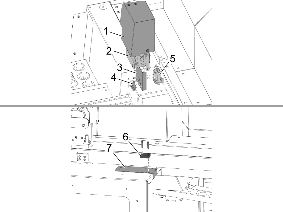
    Ta bort kåpan till autodörrmotorn [1] och autodörrmotorenheten [2].

    Montera den nya fästet [3] till närvarobrytaren på det befintliga närvarobrytarblocket [5]

    Koppla in närvarobrytaren för dörr alltid öppen [4] på fästet [3]

     Viktigt: Det finns 2 borrmallar i VMC-satsen. Det finns en VF-mall [8] och en unik mall [9] som är specifik för DC-2-maskiner. Mallen DC-2 ska användas i stället för standardmallen för VF på DC-2-maskiner.

    Montera borrmallen [7] för dörr öppen-flaggan [6] och borra och gänga 2x 10-32 hål genom dörrens plåtpanel.

    • Borr storlek: #21 eller 5/32"
    • Tryck på 10-32 NF

    Ta bort mallen och montera dörr öppen-flaggan med 2x insexskruvar med flat skalle. Montera tillbaka autodörrens motorenhet, fästet och kåpan.

    Använd medföljande shims för justera höjden mellan närvarobrytaren och öppen dörr-flaggan

    2

    Robot för laddning framifrån: 

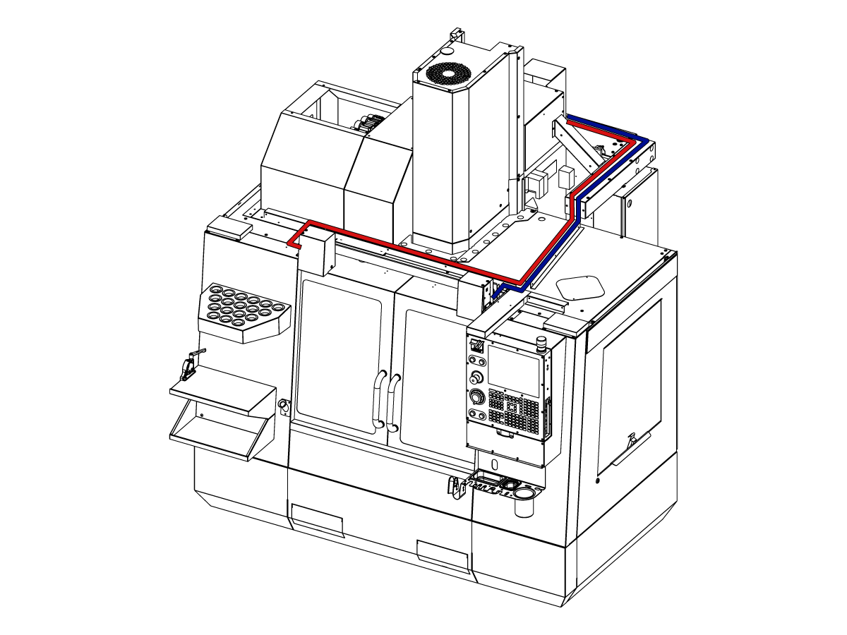
    Dra kablarna för helt öppen dörr in i styrskåpet enligt bild.

    Stäng AV strömmen till maskinen.

    Anslut till 32-0807 NÄRVARO INGEN VÄNSTER DÖRR HELT ÖPPEN till SIO PCB P27.

    Anslut till 32-0856 PROX NO RIGHT DOOR FULLY OPEN till SIO PCB P72.

    Starta upp maskinen. 

    3

    Robot för laddning från sidan:

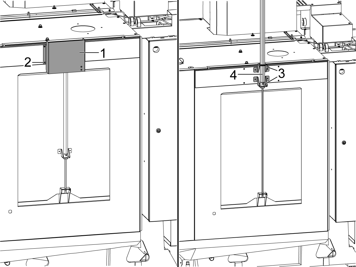
    Ta bort locket [1] och dess skruvar [2] för att exponera luftcylindern [4] i det automatiska fönstret. Höj luftcylindern [4] så att fästena [3] och luftcylindern är fästa enligt bilden.

    Anslut de medföljande grå och gula luftledningarna till autoföntrets luftcylinder - portarna på luftcylindern har grå och gula buntband som visar var varje slang ansluts.

    Montera locket [2] över luftcylindern i det autofönstret.

    4

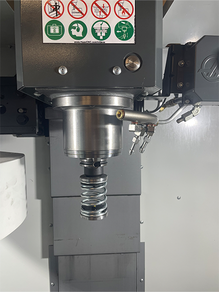
    • Fjädermataren görs med ett skaft för att passa antingen en 25mm eller 1 tum verktygshållare
    • Detta verktyg måste ta upp en verktygshållare i verktygskarusellen.
    • Inled allaprogram med följande programsteg för att säkerställa att detaljen sitter rätt i skruvstycket:
      • Placera fjädertryckaren ovanför detaljen
      • Flytta Z-axeln för att komprimera våren om 0,50 inches eller 12,7 mm
      • Öppna skruvstycket med en sekunds fördröjning
      • Stäng skruvstycket med en sekunds fördröjning

    Anm.: Fjädertryckarens artikelnummer är: 

    • 30-12642 FJÄDERINMATARE  Hållaren på 25 mm (1,0”) säljs separat.

    Cobot Installation

    1

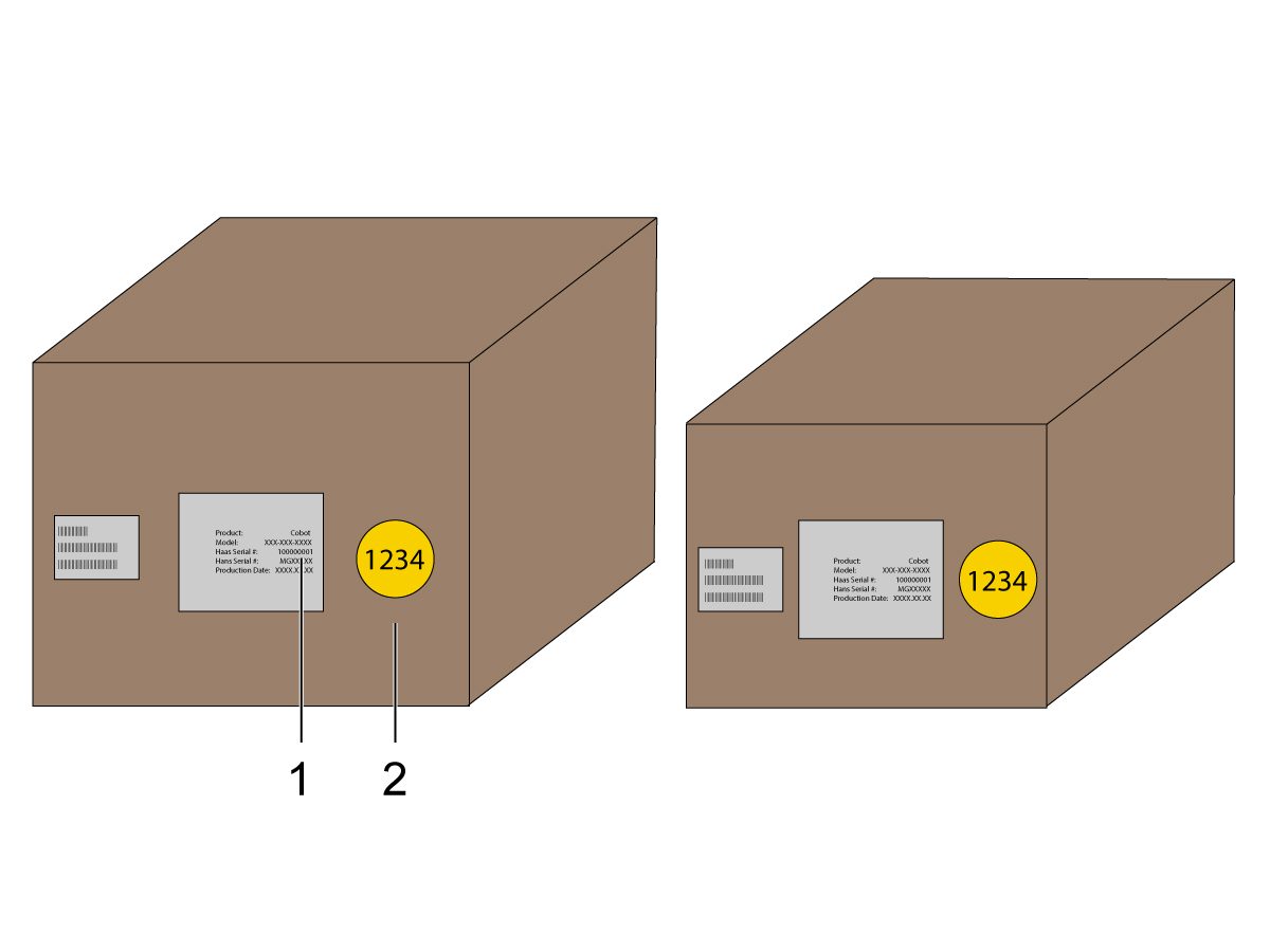
    Kontrollera att Cobot och dess styrbox är från samma matchande uppsättning med matchande serienummer.

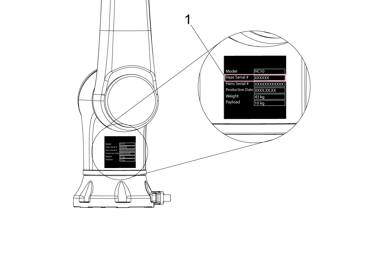
    Det finns en vit dekal med Haas serienummer [1]. Se till att dessa är desamma på båda rutorna.

    Det finns en gul cirkeldekal med ett identifieringsnummer [2]. Se till att dessa är desamma på båda rutorna.

    2

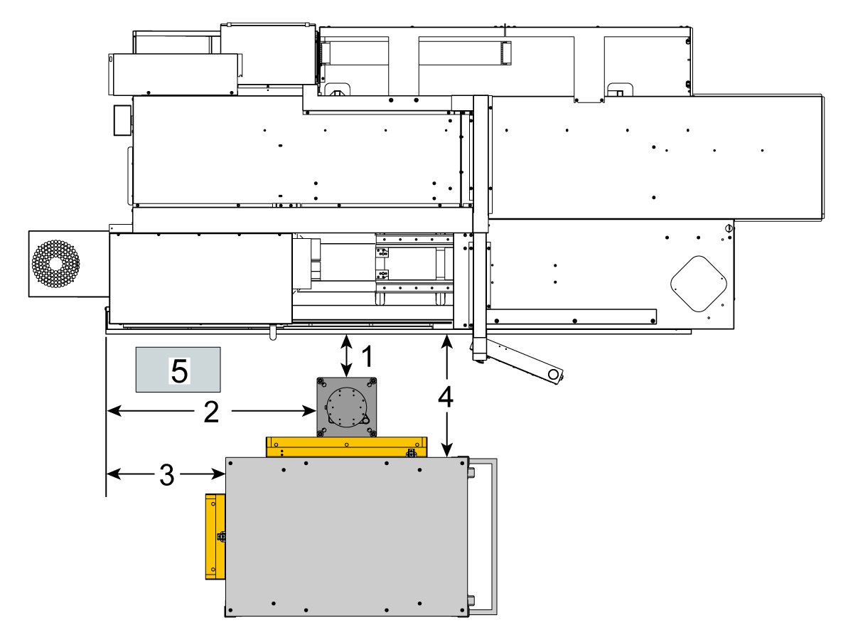
    Mät detta avstånd från maskinkjolen till stativets sida.

     Anm.: Följande mått är rekommenderade avstånd. Positionen kan variera beroende på användarens applikation.

    Använd måtten i nästa steg som referens för front- och sidladdningscobotar. 

    Haas Cobot10 bör installeras tillsammans med Haas Cobot-stativet. Denna piedestal är konfigurerad för att vara tillräckligt stabil när den används i enlighet med Haas definierade gränser för detaljstorlek och vikt. 

    3

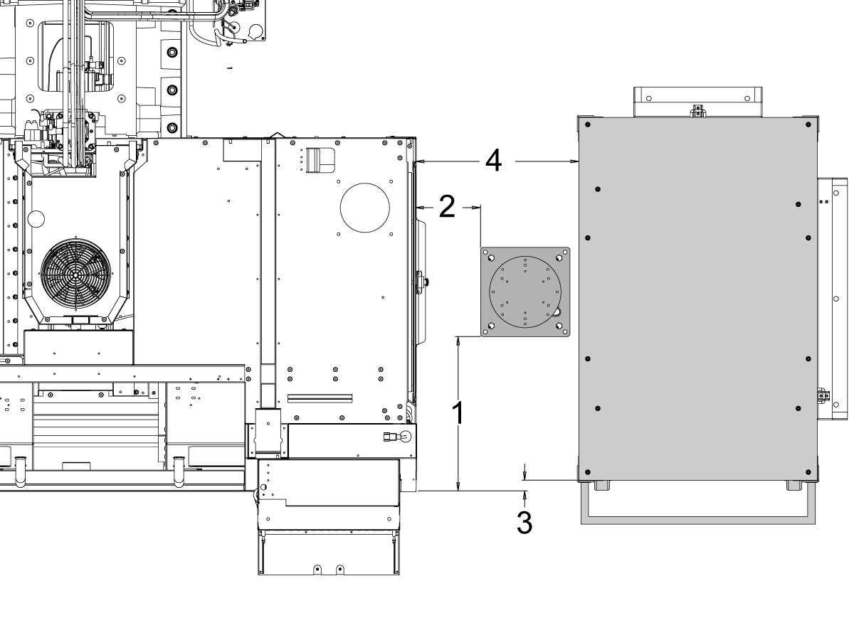
    Ladning från framsidan:

    Placera stativet och detaljtabellen på följande plats i förhållande till maskin:

    Mått Tumbaserad (tum) Metrisk (cm)
    Från maskinens framsida till stativets framsida [1] 5,5”. 14 cm.
    Från maskinens vänstra sida till vänster sida av stativet [2] 29,5”. 75 cm.
    Från maskinens framsida till detaljbordets framsida [4] 22”. 56 cm.
    Från maskinens vänstra sida till detaljbordets vänstra sida [4] 10". 25,4 cm.

    4

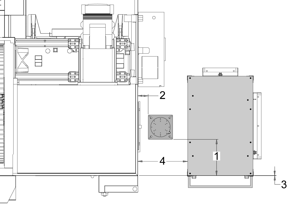
    Laddning från sidan:

    Placera stativet och detaljtabellen på följande plats i förhållande till maskin:

    Mått Tumbaserad (tum) Metrisk (cm)
    Från maskinens framsida till vänster sida av stativet [1] 20,5". 52 cm.
    Maskinens högra sida till framsidan av stativet [2] 8,5". 21,6 cm.
    Från maskinens framsida till vänster sida av detaljbordet [3] 1,5". 3,8 cm.
    Från höger av maskinen till framsidan av detaljbordet [4] 21,5". 54,6 cm.

    5

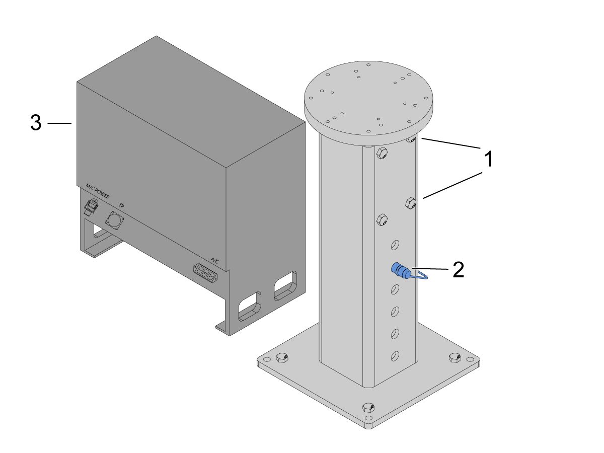
    Förankra stativet i underlaget. Rikta stativet med vattenpass.

    Observera:För den justerbara stativet, Ställ in önskad höjd genom att lossa ställskruvarna [1] och justera sedan gaffelpinnen [2]. Dra åt ställskruvarna [1] innan du installerar roboten. Placera en bubbelnivå på toppen av stativet medan du använder (x4) hex bultar vid basen för att ställa in nivån i X och Y-planet.

    Placera Cobot-styrboxen [3] direkt bredvid stativet för att säkerställa tillräckligt slack för kablarna. 

    6

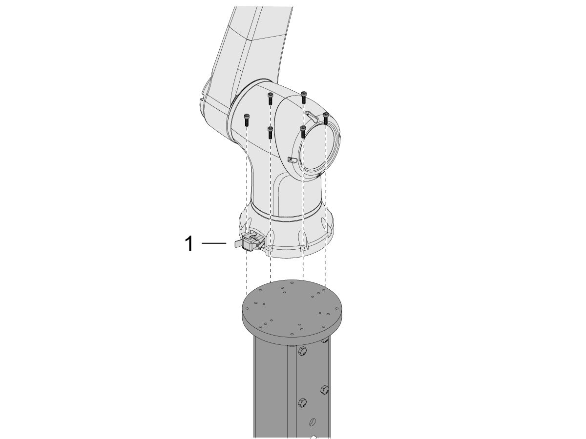
    Ta bort Cobot från transportlådan.

    Anm.: Montera adapterplattan mellan stativet och roboten vid behov.

    Montera Cobot ovanpå stativet med (6) skruvar.

    ANM.: Se till att Cobot-kabelkontakten [1] är vinkelrät mot maskinens framsida. 

    VIKTIGT: Cobot väger ca 40 lbs och måste lyftas med en enhet som säkert kan lyfta den vikten.

    7

    Inuti Cobot-förpackningen finns en liten påse [1] med reservdelar, inklusive: 

    • Säkring
    • Skruvar (2)
    • Styrboxens knappar

    Det finns en medium påse [2] fylld med en extra M12-kontakt. Denna kabel kan användas för att konfigurera in- och utgångar för I/O-slutmodulen. 

    Det finns en stor påse [3] fylld med papper och ett USB-minne som laddas ner med Cobot-programvaran.

    Förvara dessa reservdelar på en säker plats för framtida behov. 

    Robot Electrical & Air - Installation

     DANGER: Working with the electrical services required for CNC machines is extremely hazardous and can result in serious injury or death.

    Before connecting line wires to the CNC:

    • Turn off all power to the machine at the source.
    • Perform a Lockout-Tagout (LOTO) procedure to ensure the power remains off during service.
    • Verify that power has been disconnected by using an AC voltage detector on all incoming lines.

    If you are uncertain about how to safely disconnect power or perform LOTO procedures:

    • Do not proceed.
    • Contact qualified personnel or obtain appropriate assistance before continuing.

    Failure to follow these precautions may result in electrical shock, equipment damage, or fatal injury.

     Danger: Before beginning any work inside the control cabinet, verify that the High Voltage indicator light on the 320V Power Supply / Vector Drive has been off for a minimum of five (5) minutes. This waiting period ensures that residual voltage has dissipated and reduces the risk of electric shock.

    Certain service procedures involve high-risk electrical components and may pose serious injury or fatality hazards. Technicians must not attempt any procedure unless they have a complete understanding of the steps involved and the associated risks.

    If there is any uncertainty regarding a procedure, contact your Haas Factory Outlet (HFO) to arrange for a qualified service technician.

    1

    Anslut gränssnittsboxen till Haas-maskinen:

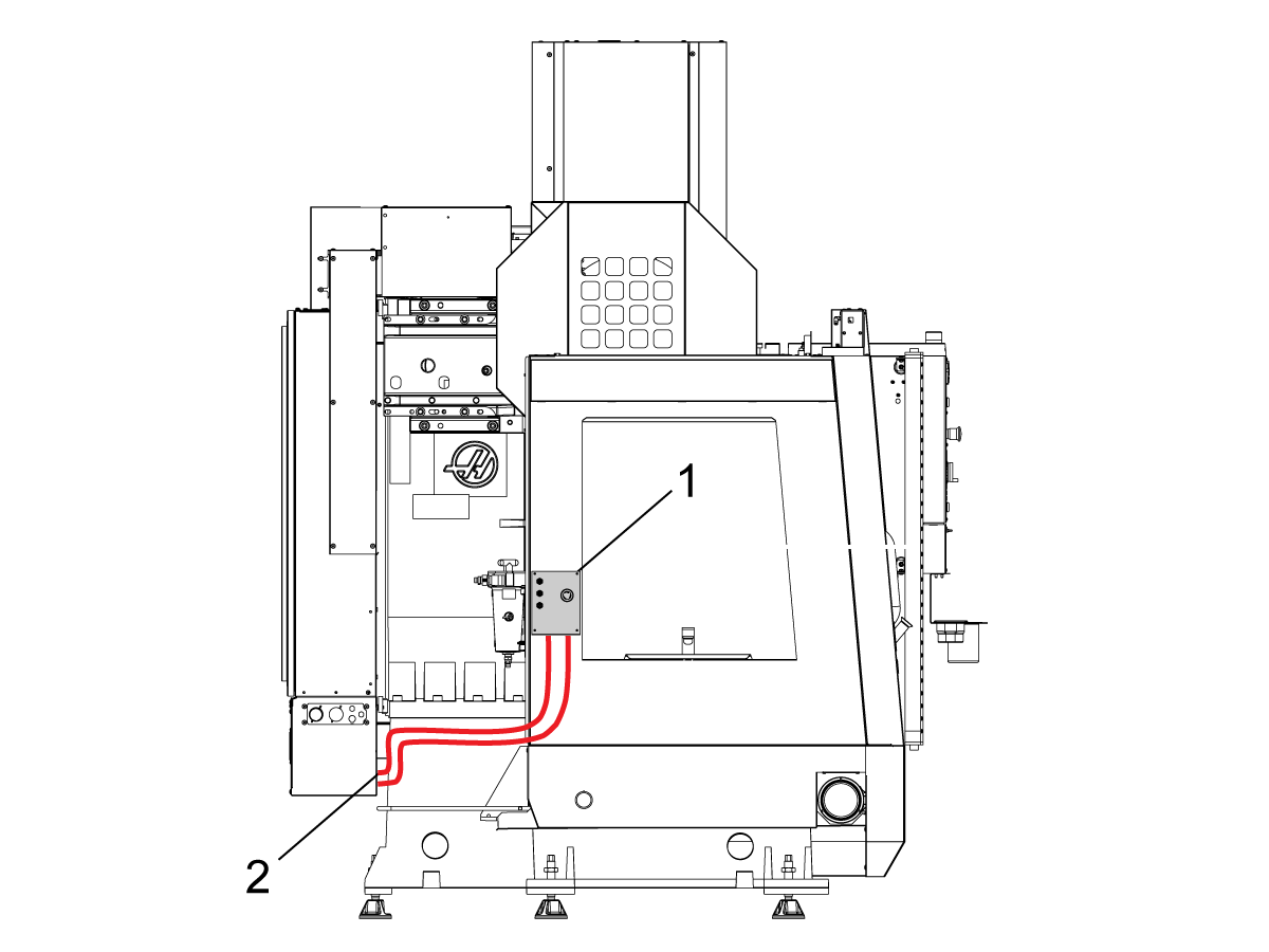
    Gränssnittsboxen för robotsäkerhetsanordningar 32-9018 har magnetfästen för att fästas på maskinens plåt. Montera den gränssnittsboxen [1] enligt bild.

    Dra gränssnittets elektriska kablar [2] längs höljet med magnetfästen och buntband. Dra kabeln genom undersidan av elskåpet.

    ANM.: För information om uppgradering av gränssnittsboxen till gränssnittsboxen för robotsäkerhetsenheter, se Gränssnittsbox för robotsäkerhetsenheter - Installation - AD0703. 

    2

    Anslut gränssnittsboxen till Haas styrsystem:

    Anslut kabel 33-8562C Nödstopp kopplingsplint till B-1B [1] och anslut installationsläge kopplingsplint till TB-3B [1] på SIO PCB.  

    Anslut användarreläerna till K9 och K10 [2].

    Kontrollera att bygeln är monterad på SIO PCB JP1.

    Anslut kabeln märkt P1 SIO till SIO PCB på P1 [3]

    OBS! Om maskinen har en Regen vektordrivning koppla ur kabel 33-0634 FILTER OV TILL IO-kortet P1 från P1 SIO och anslut den till kontakten FILTER OV FAULT på kabel 33-8562C. Om maskinen inte har en  Regen  Vector-enhet, anslut inte något till kontaktenFILTER OV FAULT.

    Anslut RJ-45-kabeln [4] till Ethernet på USB-adaptern [5] (33-0636).  Anslut USB-kontaktens ände till Maincon PCB J8 övre porten  Lägg till ett ferritfilter [6] till USB-adaptern.

    Montera 24 V DC-strömförsörjningsenheten [7] på vänster sida i styrskåpet och anslut den till kontakten märkt 24V PS på kabel 33-8562C. Anslut 33-1281 [8] till 24 V DC-strömförsörjningsenheten [7] och anslut till P3 på PSUP PCB 

    .

    3

    För MM/SMM CM/CL-serien-maskiner utan XMR

    Om P3 upptas av en bygel ansluten från P3 [10] till P7 [9] på PSUP PCB, behövs en delningskabel för att låta 24VDC-strömförsörjningen [7] anslutas till 120VAC-kontakterna på PSUP. Anslut hankontakten på splitterkabeln till P3 [10] och anslut sedan bygeln från den kabeln till P7 [9] och även kabel 33-1281 [8].

    Anm.: Kontrollera att byglingskabeln är ansluten där de röda ledningarna möter den röda från fördelningskabeln.

    4

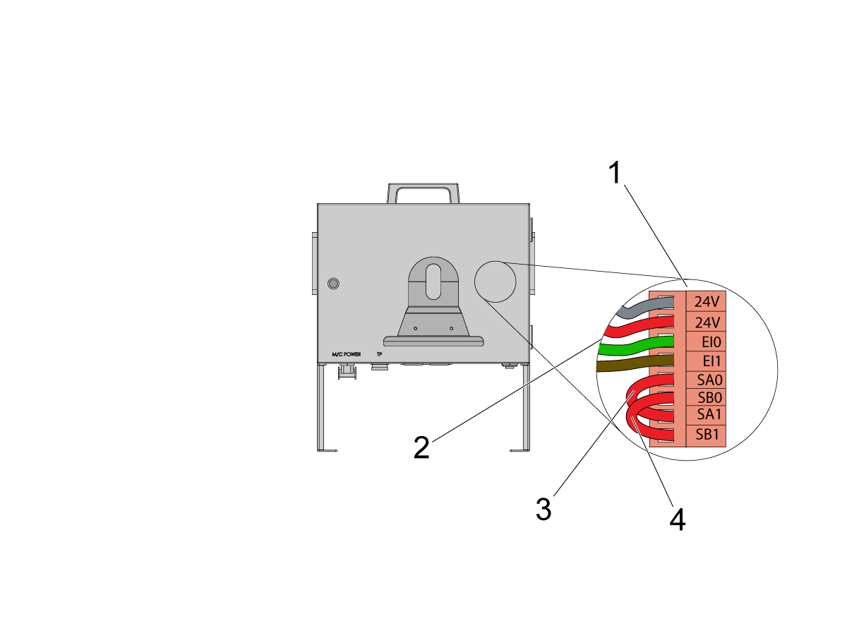
    Inuti Cobot-styrboxen, installera en del av robotens signalkabel (33-1272 eller 33-1351).  För att göra detta, ta bort säkerhetskontakten [1] från Cobot- styrboxen för att installera de olika färgade kablarna på deras respektive plats

    33-1272/33-1351 kablar [2] går till säkerhetskontakt:

    • Grå ledning till övre 24V
    • Röd ledning till nedre 24V
    • Grön ledning till EI0
    • Brun ledning till EI1
    • Bygel [3] från SA0 till SA1
    • Bygel  [4] från SB0 till SB1

     ANM.: Övriga ledningar i denna kabel används inte. Sätt lite eltejp på varje kabelledning och Ziptie de kvarvarande oanvända ledningarna. 

    5

    Viktigt: Efter att ha installerat alla kablar från robotens signalkabel, se till att säkringen [1] alltid är installerad för att skydda Cobot-styrboxen.

    6

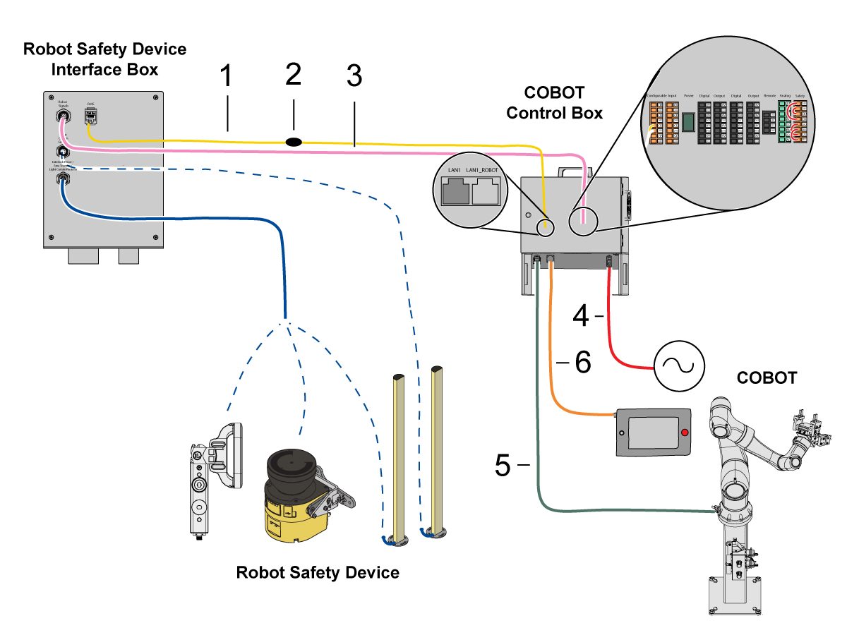
    Anslut Cobot till gränssnittsboxen: 

    Anslut RJ45 Ethernet-kabeln [1] från Cobot-styrboxen till gränssnittsboxen. Lägg till ett ferritfilter [2] till RJ-45-kabeln.

    Anslut robotens signalkabel [3] från Cobot-styrboxen till gränssnittsboxen. 

    Anslut 120 VAC Cobot strömkabel [4] till den externa strömkällan.  

    Anslut robotens strömkabel [5] från styrboxen till Cobot.

    Anslut teach-hängpanel [6] från styrboxen till lära hängpanelen. 

    ANM.: Läs mer om installation av skyddsstängsel, områdesskanrar och ljusridåer i avsnittet Skyddsutrustning för robotar nedan.

    7

    Se till att fjärrpulsgeneratorn är installerad på maskin.

    Observera: Läs mer om RJH-XL-installationen finns i Fjärrstyrt jobbhandtag – Stor beröring (RJH-XL) – Installation – AD0533. 

    8

    Steg 7 till 10 är instruktioner för kabeldragning och slangdragning för pneumatiska gripare. Se avsnittet om installation av gripdon på denna sida angående mekanisk montering.

    Skapa tillräckligt slack på luftslangarna när du monterar den dubbla magnetluftventilen på sidan av stativet. Se till att den är i en position där den inte är i vägen. Dra tryckluftsledningen [1] under maskinens baksida mot CALM-skåpet enligt bild.

    9

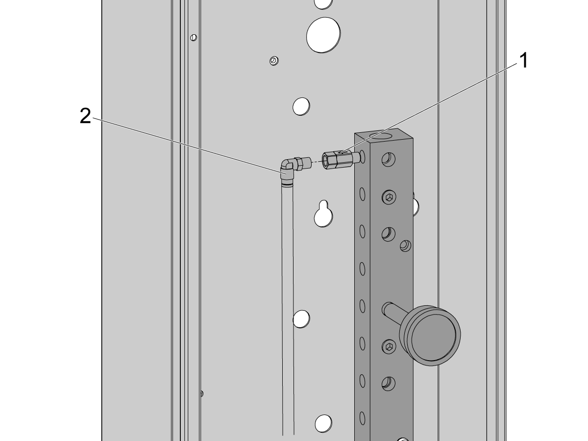
    I CALM-skåpet, ta bort en plugg från en av CALM-fördelningsblocket portar och montera reducerventilen [1] (58-1863) på portarnas infästning. LED inmatningstryckluftsledninggen [2] från den dubbla solenoidventilen (från föregående steg) till CALM-skåpet och anslut tryckluftsledningen till reduserventilen.

    Slå på tryckluften till maskinen.

    10

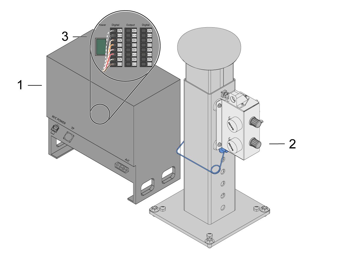
    Se till att styrboxen är avstängd [1].

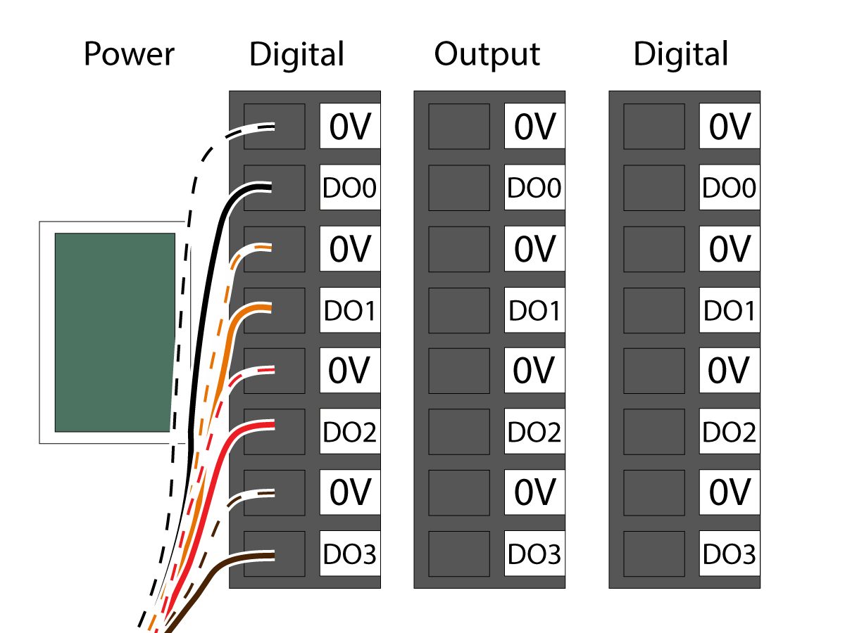
    Anslut solenoidventilens kabeln från den dubbla luft solenoidventil [2] till Digital Output på Cobot-styrboxen [1]. Ta bort kontakten från Cobot-styrboxen.

    11

    Anslut strömkabeln till gripdonsmagnetventilen (33-1276/33-1341) till terminalen Dogotal Output i styrboxen. Anslut ledningarna med olika färger på respektive plats:

    • Svart/vit kabel till 0V
    • Svart kabel till DO0
    • Orange/vit kabel till 0V
    • Orange kabel till DO1
    • Röd/vit kabel till 0V
    • Röd kabel till DO2
    • Brun/vit kabel till 0V
    • Brun kabel till DO3

    Slå på styrboxen.

    Robot Safety Device

    VIKTIGT: ANVÄND INTE ROBOTEN FÖRRÄN DU HAR KONFIGURERAT OCH TESTAT KORREKT FUNKTION FÖR SKYDDSUTRUSTNINGEN.

    Ljusridå

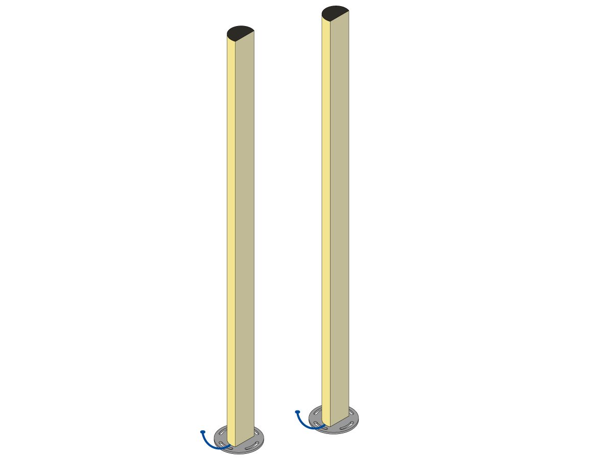
    Cobot-paket levereras med ljusridåsändaren och mottagaren som standardsäkerhetsenhet. Följ proceduren nedan vid installation av ljusgardiner: 

    Installera ljusridå

    ANM.: Om områdesskannern eller satsen HC10 förberedd maskin har beställts kommer det också att finnas en 1M ljusridåmottagare och sändare. Dessa levereras med alla Cobotar. 

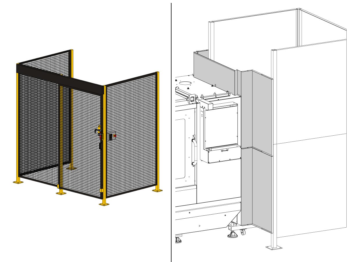
    Robotstängsel:

    Om maskinen levererades med stängseltillval måste robotstängslet och grindlåsenheten installeras på maskinen. Följ proceduren nedan vid installation:

    Installation av skyddsstängsel för robot

    När stängslet har monterats ska stängselpanelen monteras mellan maskinen och robotstängslet.

    Områdesskanner

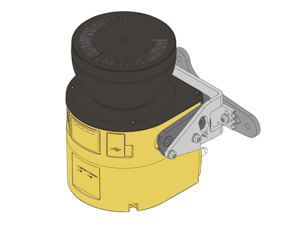
    Om maskinen har levererats med områdesskanner som tillval måste områdesskannern installeras och konfigureras för utrymmet. Följ proceduren nedan vid installation: 

    Installation av områdesläsare

    First Power-UP

    1

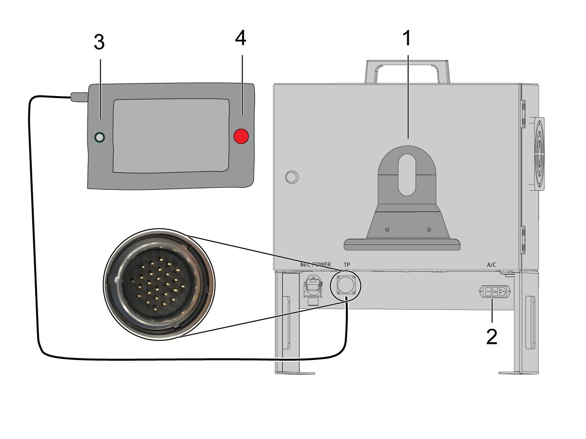
    Montera manipulatorhållaren [1] på Cobot-styrboxens framsida. 

    Starta Haas-maskinen. 

    Slå PÅ Cobot-styrboxen med vippströmbrytaren [2].

    Slå PÅ Cobot-manipulatorn genom att trycka på cirkeln [3]. 

    Kontrollera att Cobot-manipulatorns nödstopp [4] är släppt. 

    2

    Observera: Cobot teach-hängpanel kommer att ha en popup ber om att infoga användarnamn och lösenord. Logga in på manipulatorn med följande inloggningsuppgifter:

    • Användarnamn: admin
    • Lösenord: admin

    Välj programkörningsläge. Tryck på Aktivera. 

    Välj joggningsläge [1].

    Flytta varje led till nollposition med knapparna Flytta noll [2]. 

    3

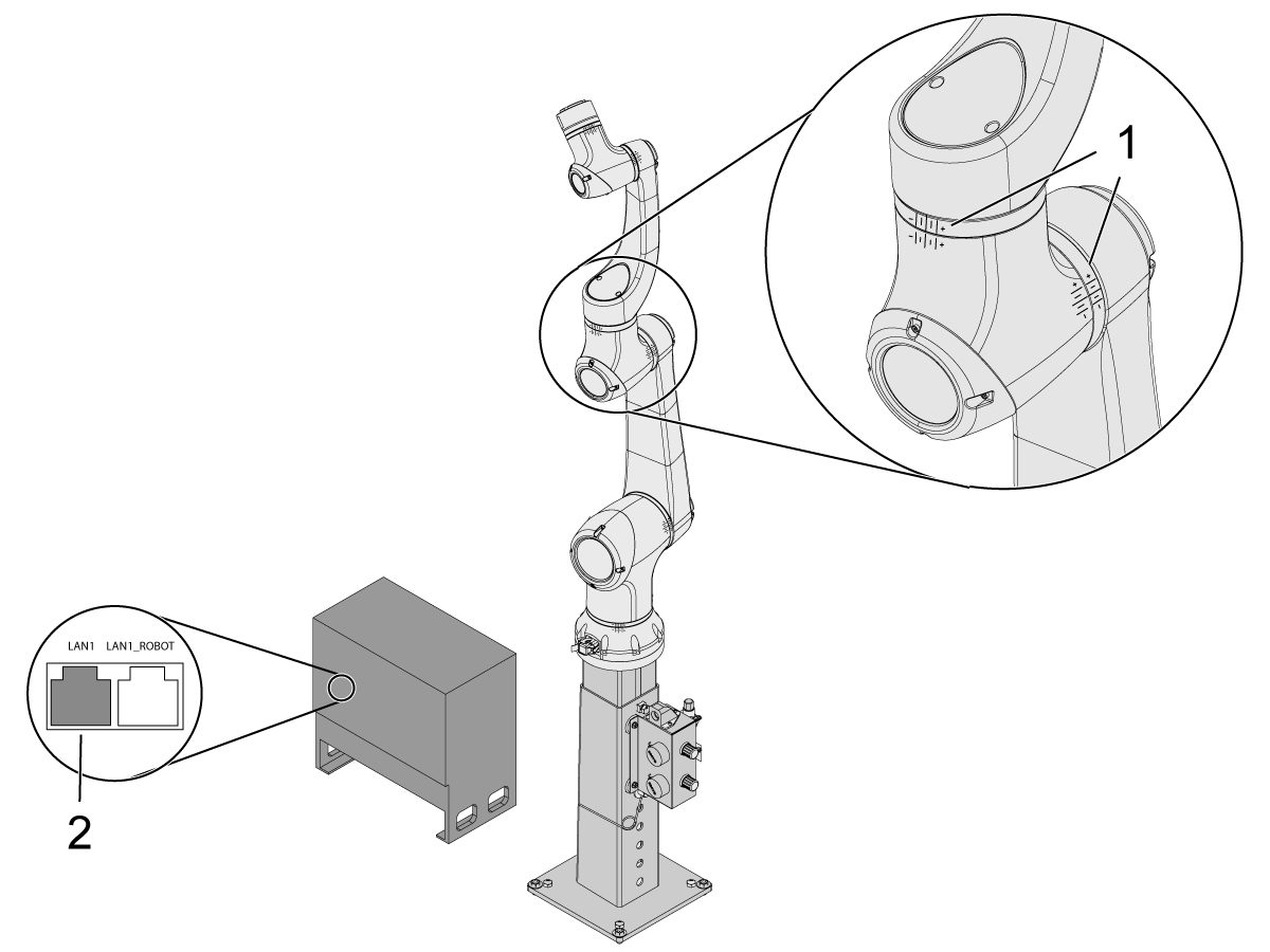
    Kontrollera, när roboten är i nollposition, att de korsade linjerna [1] är inriktade på varje led på coboten. 

     viktigt: Om några gemensamma hash linjer [1] inte justeras, jogga den specifika fogen i enlighet med detta tills alla hash linjer [1] gör justera. Denna position kommer att ställas in i nästa steg som den nya Cobot-nollpositionen.  

    Anslut en Ethernet-kabel [2] från cobot-styrboxen till en dator.

    På datorn ändrar du adapterinställningen för att aktivera Ethernet-porten. 

    Obs! Se nästa steg för hjälp med att ändra adapterinställningarna.

    4

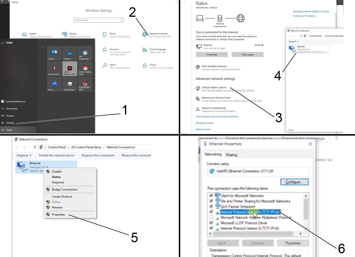
    Om du vill ändra adapterinställningarna öppnar du inställningssidan [1] på datorn och klickar sedan på ”Network Internet” (Nätverk och Internet) [2] som kommer att visa nätverksstatussidan.&

    Klicka på ”Change adapter options” (Ändra adapteralternativ) [3] och högerklicka sedan på Ethernet [4] och öppna fönstret ”Properties” (egenskaper) [5]. Därifrån väljer du alternativet Internet Protocol version 4 (TCP/IPv4) [6] och klickar på OK. 


    5

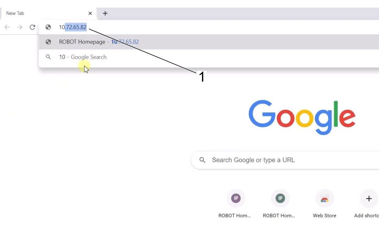
    Ethernet-inställningarna kommer nu att vara korrekta. Öppna ett webbläsarfönster och skriv in IP-adressen för Coboten [1]. 

    Obs! Detta är samma process som att ansluta en bärbar dator till en HRP-1/2/3. Läs mer om hur du ansluter till Coboten via Ethernet, se videon på sidan HRP-felsökning som finns i avsnittet Ansluta och jogga Haas robot. 

    6

    Ladda ner HRTool via HBC. I servicesektionen på HBC, gå till Utilities (Verktyg) > Documents and Software (Dokument och programvara)> 01 Control Software (styrprogram)> 01 Next Generation Control (NGC-system)> 10 Cobot Software (cobotprogramvara)> HRTool.zip.

    Packa upp mappen och sök upp HRToolsMaind.exe.

    Infoga Cobot IP-adress som finns under fliken System.  Klicka på Set. 

    Gå till fliken Konfiguration på HRTool.

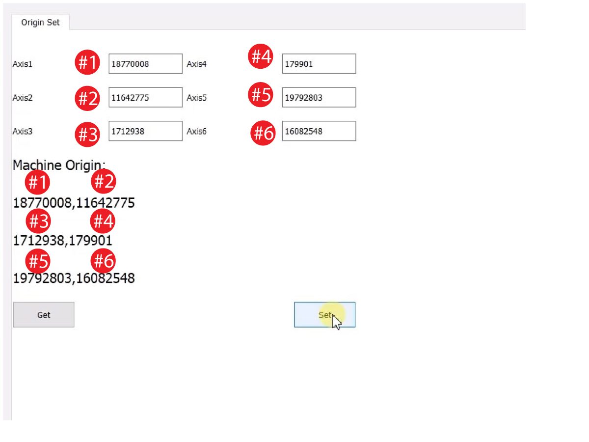
    Klicka på "get" för att se de faktiska och teoretiska omkodarvärdena. 

    Klicka på "set" för att ändra teoretiska till faktiska omkodarvärden. Detta steg anger Cobotens aktuella position som ny hemposition. 

    7

    Kontrollera att varje leds faktiska och teoretiska omkodarvärden stämmer överens. 

    ANM.: Tryck på "Set" igen om värdena inte stämmer överens. 

    8

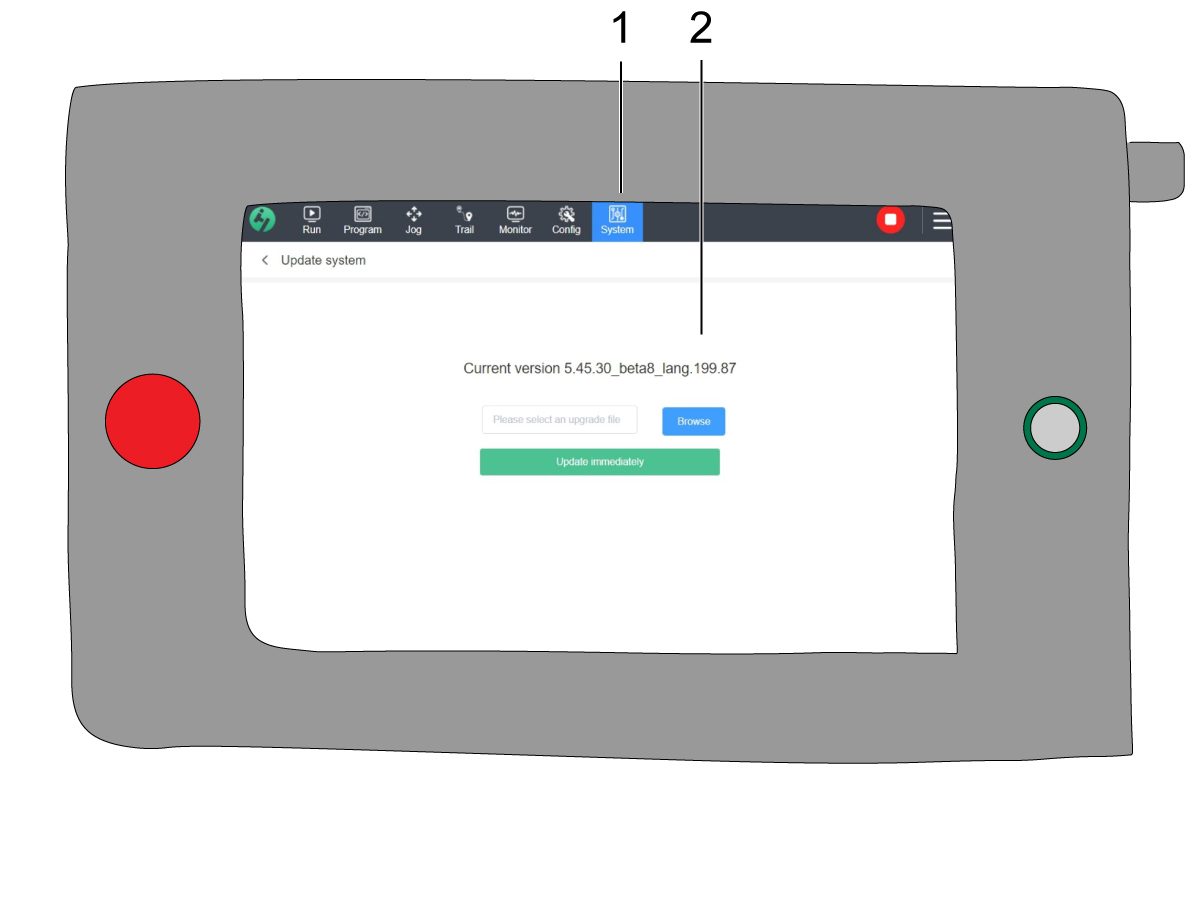
    Gå till ”System” [1] och sedan ”Update system” på manipulatorn. 

    Bekräfta att Cobotens firmware [2] är någon av följande:

    • HR5.51H.16.beta.20231213.zip
    • HR6.4.9.tmp.20240919.zip

    ANM.: Firmwareversion HR6.4.9.tmp.20240919.zip är kompatibel med cobotar av alla storlekar.

    Se kapitlet Haas Cobot – Underhåll angående procedur för firmwareuppdatering.

    9

    Kör nollnollpunktsåtergång på alla axlar på Haas hängpanel.

    Sätt i USB-minnet.  Gå till Serviceläge.

    Gå till fliken Parametrar> Fabrik.  Ändra följande:

    • 1278 [1278:] Robot klar nödstopp aktiverat till SANT
    • 2191 [694:] TYP AV LJUSRIDÅ till LC_TYP_1
    • 2195 [:] Aktivera brytare främre dörr helt öppen till SANT
    • 2196 [:] Aktivera brytare främre dörr helt öppen till SANT
    • 2192 [:] Ljuströskel för ljusridåer till 0

    Tryck på [SETTING] (inställning).

    Ställ in inställningarna:

    • 372 – Typ av detaljladdare på 3: Robot
    • 376 – Aktiverad ljusridå på PÅ

    10

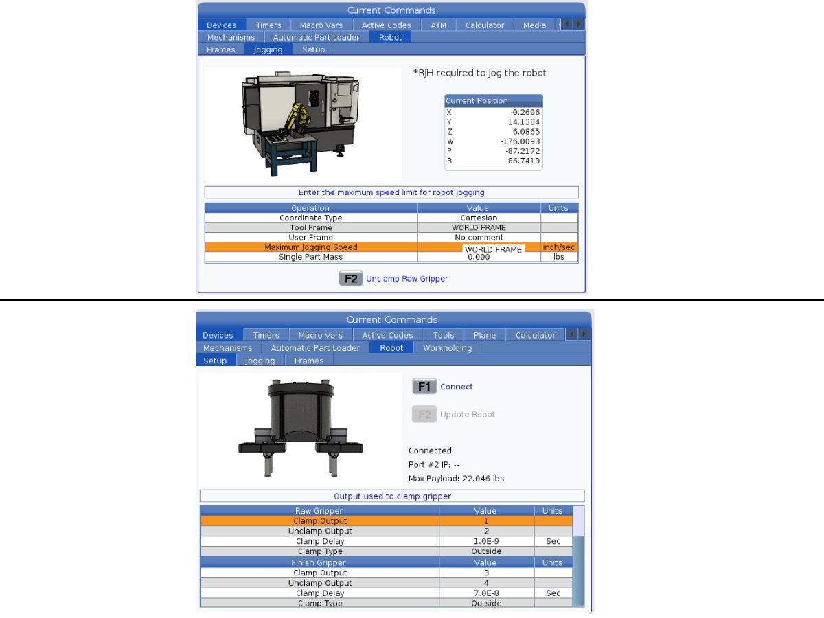
    På Haas hängpanel, tryck på [CURRENT COMMANDS].

    Gå till Enheter>Robot>Joggning . Ändra följande:

    • Högsta pulsmatningshastighet till 7,9  tum/s

     ANM.: Joggningsinkrement på RJH är en procentandel av denna högsta hastighet. För att minska avståndet som roboten färdas för varje fästing på joggningshjulet måste du ändra dinMaximala joggningshastighet till ett lägre värde.

    Gå till Inställningar -fliken. Ändra följande:

    • Max Robot Speed (Max robothastighet) till 118 tum/sek (2 000 mm/sek). 
    • Ange gripdonets  nettovikt. Se layoutritningarna på vår webbplats (layoutritning för engripare ELLER  layoutritning för dubbelgripdon) för att hitta rätt värde för denna inställning

    Varning! Del inställning av detta värde kan leda till att robotarmens rörelser bli felaktiga. 

     
    • Antal gripare - Ange antalet gripare.
    • Råmaterialgripare griputgång till 1
    • .
    • Råmaterialgripdon lossningsutgång till 2.
    • Råmaterialgriparens fördröjning till grip/lossa i sek.
    • Råmaterialgripare griptyp till utvändig/invändig.
    • Detaljgripdonets griputgång till 3.
    • Detaljgripdonets lossningsutgång till 4.
    • Gipare för färdig detalj gripfördröjning  till grip/lossa-fördröjning i sek.
    • Råmaterialgripare griptyp till  utvändig/invändig.

    Stänga av manipulatorn

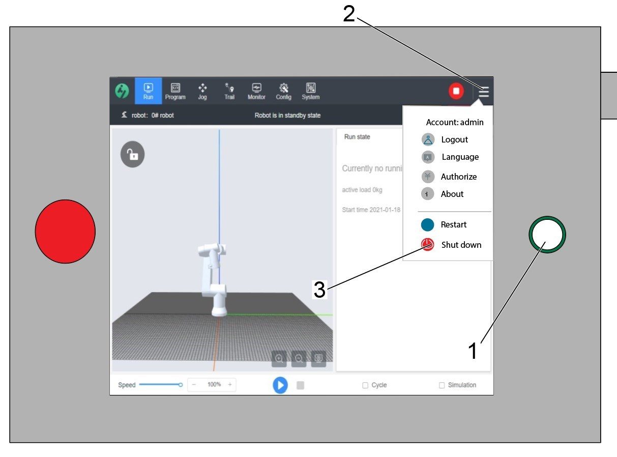
    Varning! Stäng inte av manipulatorn med på/av-knappen [1]. Detta kan orsaka förlust av systemfiler i cobotens styrbox.

    Stäng av manipulatorn genom att trycka på de tre strecken i det övre högra hörnet [2] så att alternativmenyn öppnas till höger.

    Välj ”Shut down” [3] för att initiera avstängningssekvensen för cobotens styrbox.

    Viktigt: Om du stänger av manipulatorn på fel sätt kan viktiga filer skadas på cobotens styrbox. Detta kan leda till att coboten inte kan användas förrän systemfilerna har återinstallerats i styrboxen.


    Security Risk Level

    1

    VIKTIGT: En lämplig riskbedömning måste utföras och lämpliga säkerhetskrav måste uppfyllas. 

    2

    Ställ, med hänsyn till riskbedömningen, in lämplig säkerhetsrisknivå på cobotens manipulator. Navigera till Konfiguration > Allmänna restriktioner och tryck på önskad säkerhetsrisknivå [1] från 0 till 5.

    Använd koden "admin" i säkerhetsverifieringen för att ändra säkerhetsnivån.

    Observer: När säkerhetsrisknivån är lägre har roboten lägre maxhastighet, kraft osv. När säkerhetsrisknivån är högre kommer roboten att ha en högre maximal hastighet, kraft, etc. 

    Denna säkerhetsrisknivå kommer att beräkna den maximala tillåtna kraften, hastigheten, kraften, momentum, armbågshastigheten och armbågskraften [2] som Coboten kommer att motstå innan larm 9150.10017 Collison Stop-fel utlöses. 

    VIKTIGT: Robotens programmerade hastighet kan inte vara större än den tillåtna hastigheten från säkerhetsrisknivån. 

    ANM.: För mer information om larm, se Haas Cobot – Felsökningsguide. 

    Activation

    1

    Gå till HAAS SERVICEPORTAL och ladda ner de senaste konfigurationsfilerna.

    Ladda ner konfigurationsfilerna för säkerhetsautomation på framsidan/sidan.

    Läs in korrigeringsfilen för alternativ konfiguration i kontrollen. Se NÄSTA GENERATIONS KONTROLL-KONFIGURATIONSFIL-LADDA NER/LADDA Förfarande. 

    2

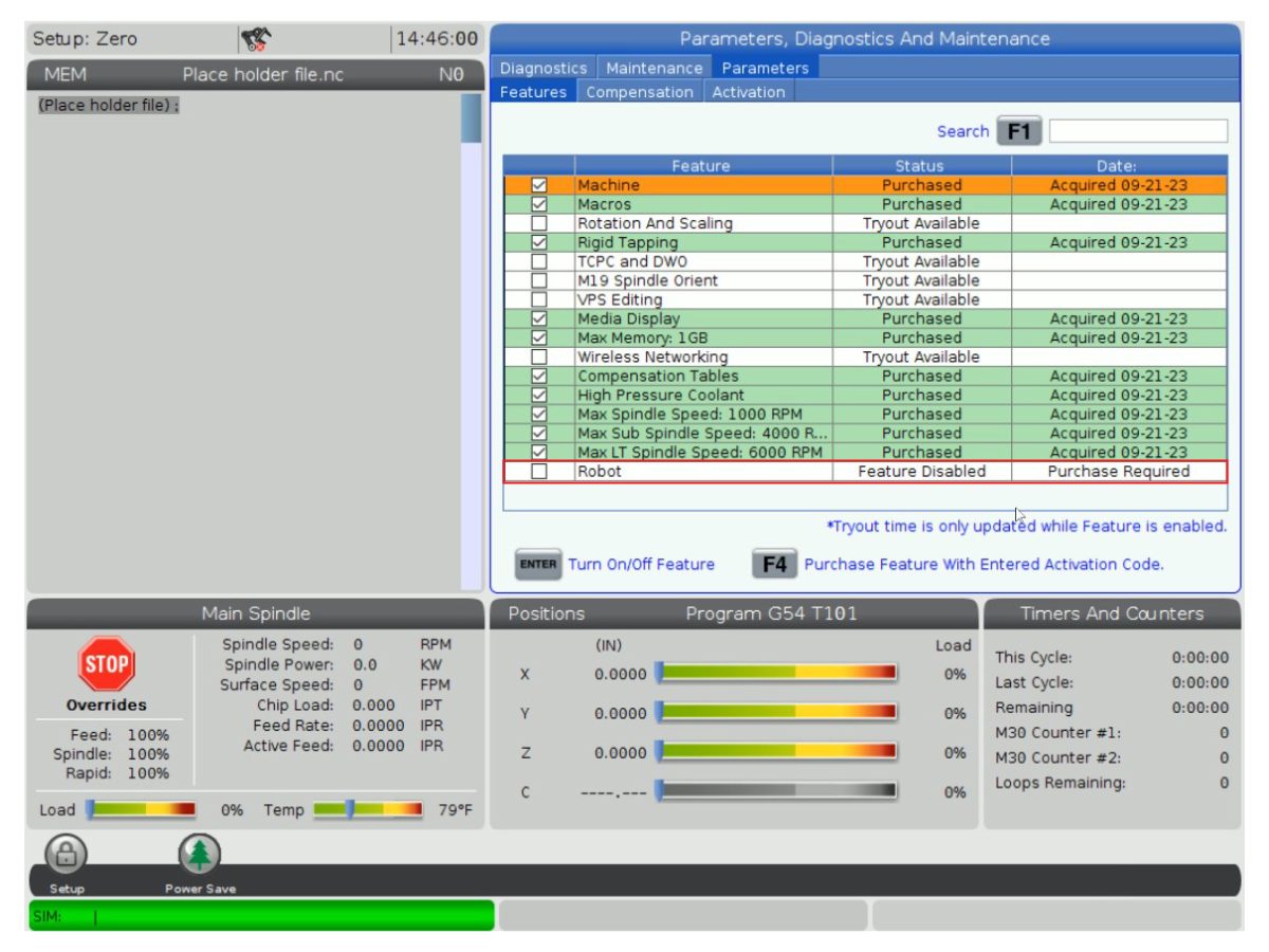
    Gå till Parametrar>Funktioner>Robot för att kontrollera att robotfunktionen visas längst ned.

    3

    Tryck på [CURRENT COMMANDS].

    Gå till fliken Enheter>Robot>Inställningar [1].

    Tryck på[E-Stop].

    Tryck [F1]för att ansluta roboten[2].

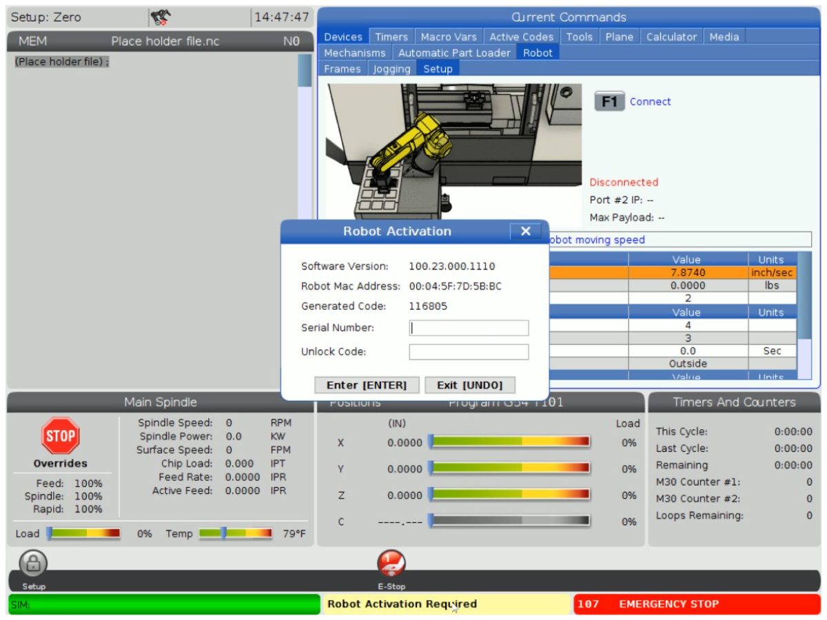
    Första gången en robot ansluts till en maskin måste robotfunktionen låsas upp. Detta popup-fönster visar maskin aktuella programvaruversion, robotens Mac-adress och en genererad kod. Ange denna information i HBCför att få upplåsningskoden.

    4

    På HBC, gå till fliken Service [1].

    På skärmens vänstra sida klickar du på Aktiveringar [2] och väljer sedan cobotinstallation [3] för att starta processen för att hämta cobotupplåsningskoden.

    I det första steget anges maskinens serienummer [4] och cobotens serienummer [5] i fälten på HBC.

    När du har angett rätt information trycker du på Nästa [6] i det nedre högra hörnet och fortsätter genom stegen tills du får upplåsningskoden.

    Obs! Se till att du är på fliken cobotinstallation [3] och inte på fliken robotinstallation. Robotinstallationen används endast för Haas robotpaket. Användning av robotinstallationen för Haas Cobots kommer att resultera i en ogiltig upplåsningskod.

    5

    Ange cobotens Haas-serienummer [1] och lås upp koden för att ansluta roboten till maskinen. 

     Obs! Detta steg kan endast utföras av en HFO-servicetekniker.

     Observera: Innan Coboten aktiveras måste maskinen vara aktiverad. Följ proceduren maskinaktivering/tidsförlängning -NGC .

    När roboten har anslutits till maskinen visas ett gult meddelande om att aktivering av roboten har slutförts längst ned på Haas-skärmen.

    6

    Frigör [E-STOP] och tryck på RESET för att rensa larmet. 

    Tryck på knappen [HANDLE JOG]. 

    Tryck på [CURRENT COMMANDS]  och gå till fliken Enheter > Robot > Joggning.

     Obs: Roboten i inställningsläge kan endast pulsmatas F2 -knappen när RJH trycks in. Se avsnittet Inställnings-/körningsläge nedan.

    Tryck på knappen Joint (Led) på handjoggningsenheten för att använda ledkoordinater.

    Flytta roboten till en åtkomlig plats för montering av gripdonen.

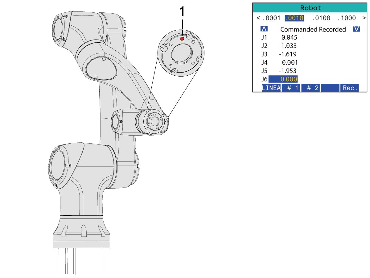
    Jogga J6 till positionen 0,0000.

    Platshålet ska centreras överst.

    Anm.: Tryck [Emergency Stop] innan du arbetar på roboten.

    Gripper Installation

    1

    Stäng luften till maskinen med ventilen i CALM-skåpet och dra i tryckavlastningsventilen för att tryckavlasta systemet.

    2

    För ett dubbelt gripdon:

    Det finns två versioner av dubbelverkande gripdon för denna sektion, som båda har samma installationsprocess.

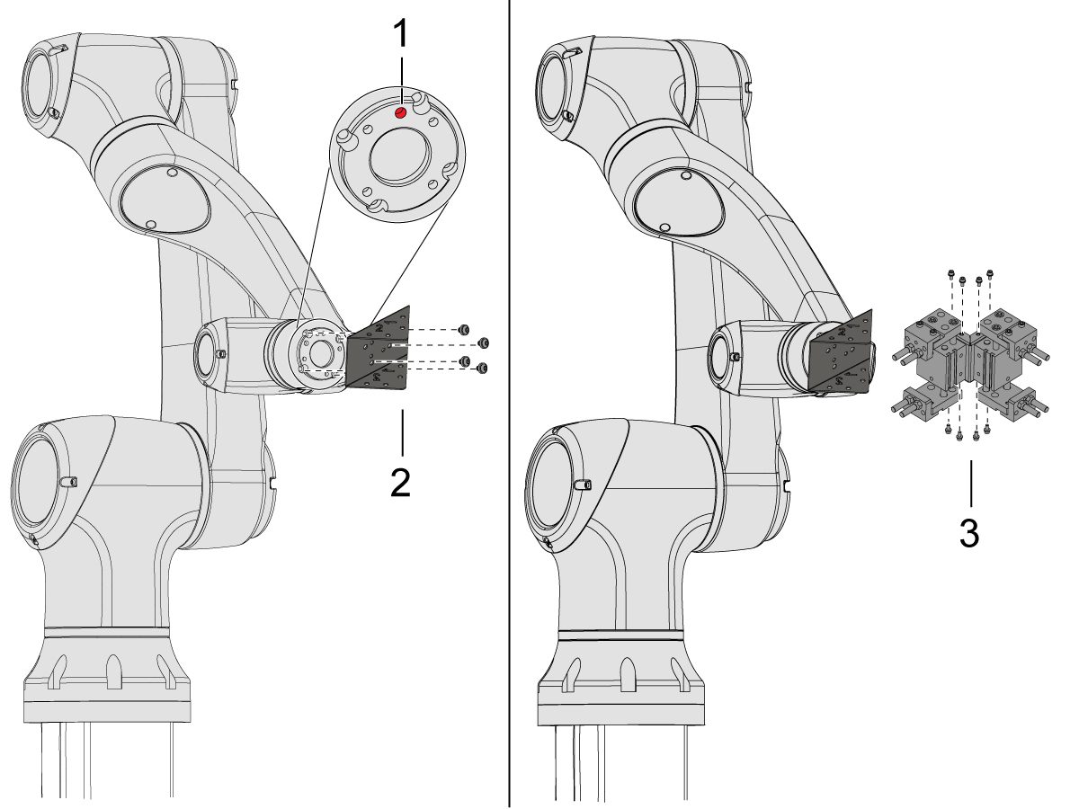
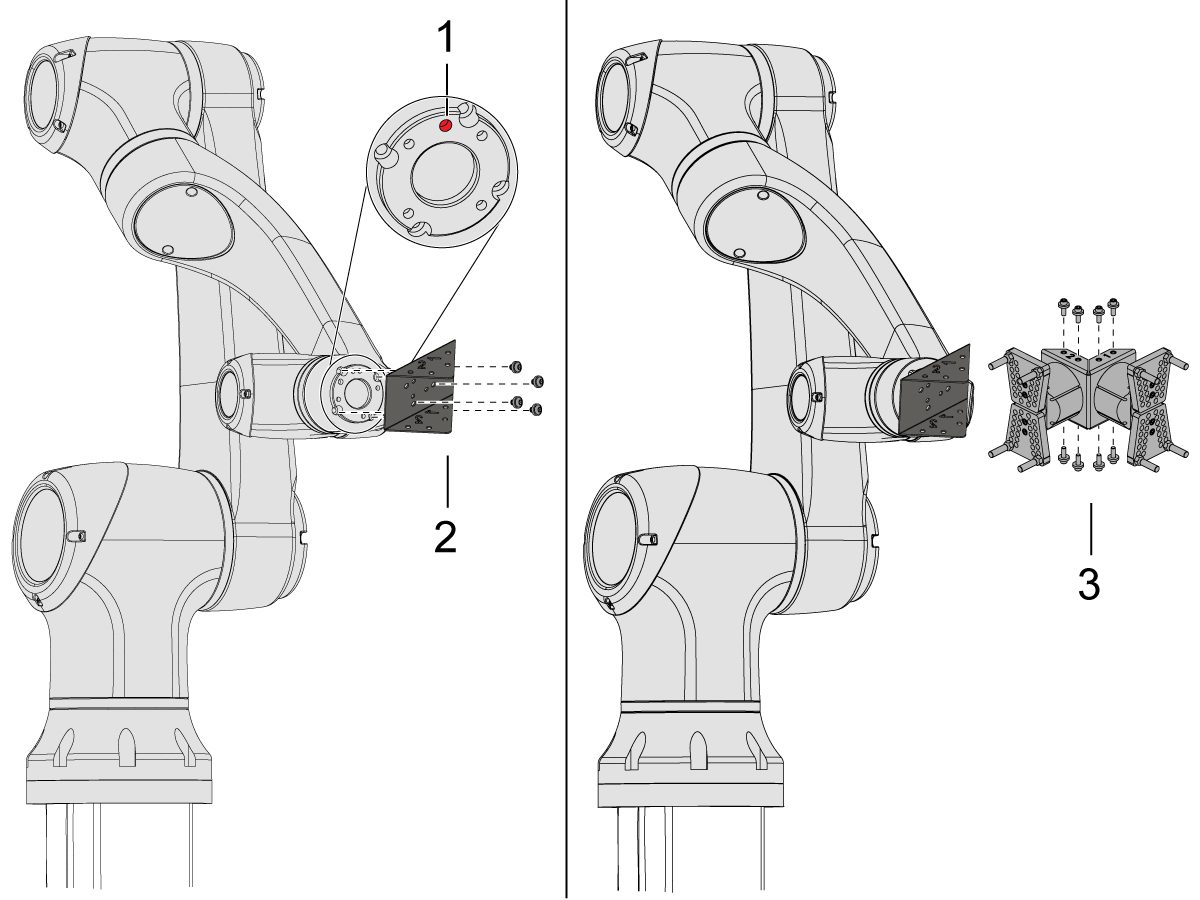
    Jogga roboten så att platshålet [1] är centrerat ovanpå.

    Montera adapterplattan [2] i änden av robotarmen.

    Montera gripdonsenheten [3] på adapterplattan [2].

    Observera: Se till att installera gripare 1 (som har de orange och lila buntbanden) på gripare 1 adapterplatta sektionen. 

    3

    För vinklade enkla gripdon:

    Jogga roboten så att platshålet [1] ska centreras ovanpå.

    Montera vinkeladapterplattan [2] i änden av robotarmen.

    Montera det enkla gripdonet [3] på vinkeladapterplattan [2]. 

    4

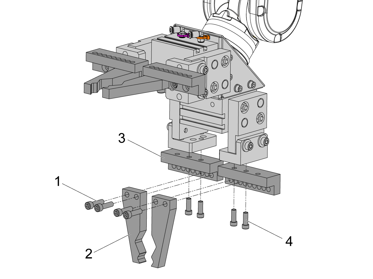
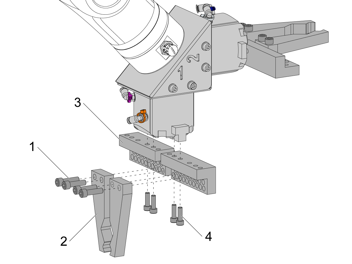
    Montera gripfingarna genom att ta bort griparplattorna från griparstommarna.

    Montera stånggripdonets skruvplattor [3] med (8) SHCS M6 skruvar [4]. Dra åt med 10 ft-lb.

    Montera stånggriparens fingrar [2] med (x8) SHCS 1/4-20 [1]. Dra åt med 13 ft-lb.

    5

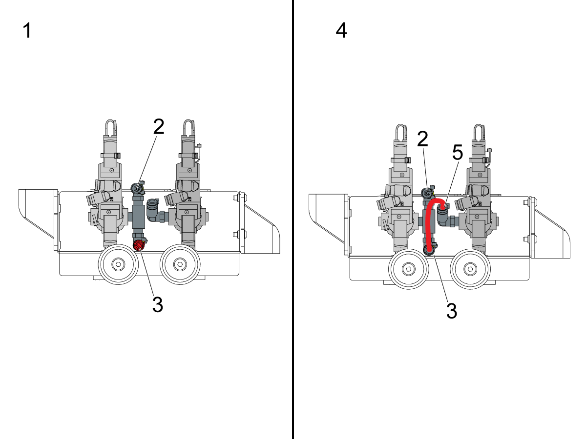
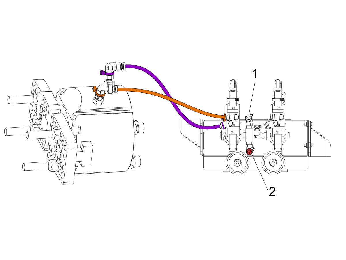
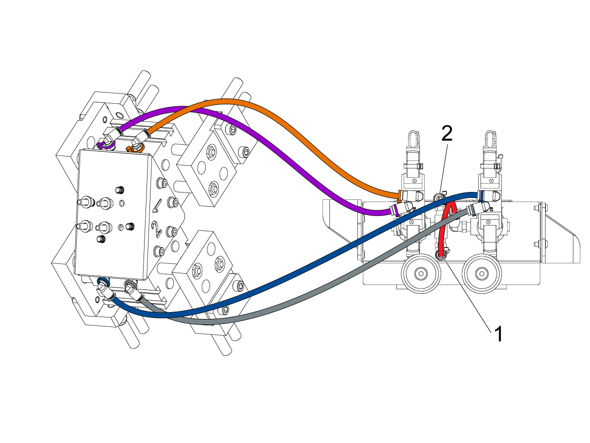
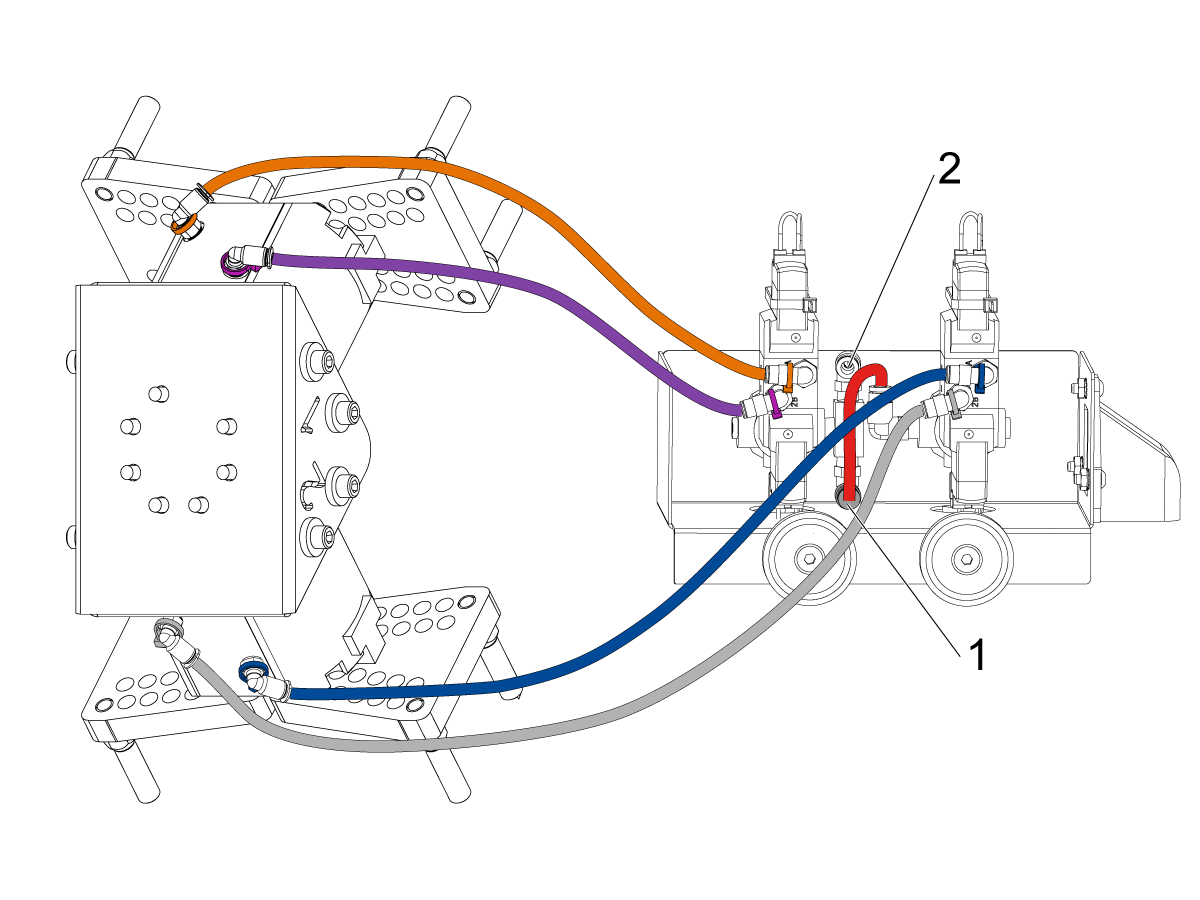
    Konfigurera den dubbla magnetventilen för pneumatiska gripdon beroende på konfiguration med enkelt [1] eller dubbelt [2] gripdon. 

    För enkla gripdon [1]: anslut inkommande luft till kopplingen [2] och behåll pluggen i den andra änden av kopplingen [3] enligt bild.

    För dubbla gripdon [4]: ta bort pluggen i kopplingen [3] och fäst en liten tryckluftsslang till den andra magnetventilen [5]. Anslut sedan den inkommande tryckluftsslang till tillbehöret [2] så att båda solenoiderna tar emot luft.

    6

    För enkelt gripdonla gripare:

    Dra (x2) tryckluftsledningarna från griparen till samma färgkodade montering på den dubbla solenoidventilen. 

    Säkra tryckluftsledningarna genom att linda in dem i kabelslangen. Använd kardborrebanden för att fästa kabelslangen på Coboten. Se till att det är tillräckligt spel så att kablarna inte är ansträngda när Coboten är helt utdragen.

    Sätt ingångs tryckluftsslangen till den använda solenoidventilens koppling [1]. 

    Se till att pluggen är installerad på den oanvända solenoidventilens koppling [2]. 

    7

    För dubbla gripare:

    Dra (x2) tryckluftsledningarna från griparen #1 till samma färgkodade montering på den dubbla solenoidventilen. 

    Dra (x2) tryckluftsledningarna från griparen #2 till samma färgkodade montering på den dubbla solenoidventilen.. 

    Säkra tryckluftsledningarna genom att linda in dem i kabelslangen. Använd kardborrebanden för att fästa kabelslangen på Coboten. Se till att det är tillräckligt spel så att kablarna inte är ansträngda när Coboten är helt utdragen.

    Sätt i det korta tryckluftsledningen [1] som förbinder den första solenoidventilen med den andra. 

    Sätt i inmatnings tryckluftsslang till tillbehöret [2]. 

    Parts Table Assembly

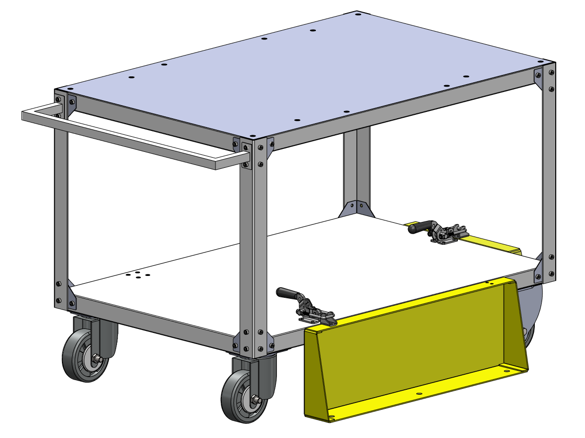
    Om tillvalet detaljbord har beställts: följ denna procedur för monteringsanvisningar:

    Haas robot – Montera detaljbordet

    ANM.: Om HC10 SATS FÖRBEREDD MASKIN har beställts behöver hjulen inte monteras om detaljbordet monteras direkt i träemballaget. 

    Verification

    Testa nödstoppet:

    • Tryck in varje nödstoppsknapp på Haas hängpanel, RJH-XL och cobotmanipulatorn. Kontrollera att maskinen genererar 107 NÖDSTOPP -larm.  Om E-STOP-knappen inte genererar 107 NÖDSTOPP alarm verifierar du kabeln. Läs in de senaste konfigurationsfilerna för att aktivera RJH-XL.

    Testa robotens säkerhetsutrustning:

    Kontrollera att en nödstopps- eller ljusridåsymbol visas på Haas hängpanel när robotens säkerhetsenhet utlöses.

    • Stängsel– Sätt i nyckeln i spärrhaken och kontrollera att de två röda LED-lamporna framför spärren är SLÄCKTA. Ta ut nyckeln ur spärrhaken och kontrollera att de två röda LED-lamporna är TÄNDA. 
    • Områdesläsare – Gå in i skyddsfältet och kontrollera att den röda LED-lampan lyser på områdesläsaren. Gå utanför skyddsfältet och kontrollera att den gröna LED-lampan lyser.
    • Ljusridå – Stör ljusridåstrålarna, kontrollera att ljusridåns utlösningsikon visas på Haas-hängpanelen. Tryck [RESET]. Gå utanför ljusridåstrålarna och kontrollera att ingen ikon visas på Haas-hängpanelen. 

    OBS!Om ljusridåns utlösningsikon inte visas, kontrollera ledningar, fördelning och fabriksinställning:  2191 [694:] TYP AV LJUSGARDIN är inställd på LC_TYPE_1.

    Testa gripdonens funktion:

    • Kontrollera att båda griparna är klämda och att klämman inte sitter fast ordentligt.
    • Tryck på [CURRENT COMMANDS]  och gå till fliken Enheter > Robot > Joggning .
    • Tryck för att gripa/lossa griparen. Tryck [F3] för att gripa/lossa råmaterialgriparen. 

    Testa handjoggningsenheten (Handratt)

    • Avdocka fjärrpulsgeneratorn
    • Tryck på knappen [HANDLE JOG] . 
    • Tryck på [CURRENT COMMANDS]  och gå till fliken Enheter > Robot > Joggning .
    • Tryck på knappen Joint (Led) på handjoggningsenheten för att använda ledkoordinater.
    • Flytta roboten till en säker plats.

    VIKTIGT: Om ett gult varningsmeddelande visas som säger "Please activate Light Curtain or Cell Safe" (Aktivera ljusridå eller cellsäker) när du försöker utföra jobb på roboten kontrollerar du att säkerhetsparametern tillämpades genom att ladda upp konfigurationsfilerna från HBC igen. 

    Verifiera drift-/driftläge

    Alla Haas CNC-maskiner är utrustade med lås på operatörsdörrarna och en nyckelomkopplare på hängpanelens sida, för låsning och upplåsning av inställningsläget. Roboten kommer att ha följande beteenden beroende på vilket läge som väljs. 

    • När Haas styrsystem är i programkörningsläge, läge 1, stoppas alla rörelser om robotsäkerhetsutrustningen utlöses. Denna rörelse kan inte startas förrän robotens säkerhetsenhet inte längre utlöses.
    • När Haas-kontrollsystemet är i inställningsläge, kan läge 2, hastighetsbegränsad rörelse, t.ex. jogga en axel av roboten, utföras för att programmera en robots rörelsesökväg, plocka upp position, ställa in en robots verktygets mittpunkt (en förskjutning), ladda och plocka upp delar från spindeln eller detaljhållaren i maskinen osv. Den programmerade banan kan också köras långsamt för att visa den programmerade robotens programmerade bana. Robotdammsugaren i inställningsläge kan endast pulsmatas medan F2-knappen RJH trycks in.

    Haas Robot - Quick Start Guide

    När roboten har installerats ställs ett jobb in enligt följande procedur.

    Haas Robot – Snabbstartsguide

    Disable the Robot

    Avaktivera roboten för att köra maskinen i fristående läge. Tryck på [SETTING] (inställning). Ändra följande inställningar:

    • 372 – Typ av detaljladdare på0: Ingen
    • 376 – Aktiverad ljusridå på AV

    5.2 Installation på svarv

    Recently Updated

    Haas Cobot 10 (HC10) – Svarv – Installation


    AD0715

    Revidering G – 07/2026

    Introduction

    Den här proceduren används för att installera Haas 10 KG Cobot (HC10).

    Obs! Den Haas-utformade arbetscellen som består av en CNC-maskin och en robot har utvärderats för efterlevnad av CE-krav. Ändringar eller variationer i Haas-cellens utformning ska utvärderas avseende överensstämmelse med tillämpliga standarder och är användarens/integratorns ansvar.

    Maskinkrav:

    • Programvaruversion 100.24.000.1001 eller senare
    • HR5.51H.16.beta.20231213.zip -version eller HR6.4.9.tmp20240919.zip version.
    • ST-10/15/20/25/28 & DS-20Y/25Y genommatning plåt (plan yta)
    • Haas autodörr
    • 34-349xB I/O-kort eller senare
    • 93-1000610 FJÄRRMANIPULATOR MED PEKSKÄRM (RJH-XL) FJÄRRMANIPULATOR - XL  

     Observera: Om maskinen har tillvalet detaljfångare installerat. Uppsamlingsbrickan kommer att störa roboten och måste tas bort. En speciell plåtpanel behöver tillverkas för att täcka/täta öppningen.

    Verktygskrav:

    • Flat liten skruvmejsel

    Fixing / Anchoring Requirements

    • The Haas 10KG Cobot (HC10) is configured and sold by Haas with a pedestal/table that is sufficiently stable when used according to Haas defined part size and weight limits. 
    IMPORTANT:  For more information directly on the Hans Cobot, refer to the Hans Robot Operation Manual for Elfin Software.

    There are 3 scenarios in which the cobot option can be installed on a Haas machine:

    1. Cobot option was ordered at the same time as the machine. Both the cobot and the machine are being installed together.
    2. Cobot option is ordered so that it can be installed on a previously installed machine.
    3. Cobot option was previously installed on a machine, but will now be moved to a different Haas machine.

    In scenarios 2 and 3, additional parts will need to be ordered under the Serial Number of the Haas machine. See the tables below for what parts are needed in the different scenarios.

    Scenario 1 - Cobot and Machine are ordered and installed together

    Component Part Number Description
    NO ADDITIONAL PARTS NEED TO BE ORDERED WHEN COBOT AND MACHINE ARE ORDERED TOGETHER

    Scenario 2 - Cobot being field installed on existing Haas Machine

    Component Part Number Description
    CHECK TO SEE IF HAAS MACHINE ALREADY HAS THESE FEATURES & PARAMETERS BEFORE ORDERING
    Robot Feature Unlock Parameter 93-1001031 Kit activates the robot feature on the Haas machine. To check if you need this kit, go to the Features tab on the Haas Control and check if the Robot option is highlighted. This kit does not include any physical parts.
    Load Type Safety Parameters 93-1000997 Front Automation Safety Parameters - Kit is needed when the cobot will be loading parts through the front door of the Haas machine. This kit does not include any physical parts and the autodoor option would need to be purchased and installed separately.
    OR  
    93-1000996 Side Automation Safetly Parameters - Kit is needed when the cobot will be loading parts through the side window of the Haas machine. This kit does not include any physical parts and the autowindow option would need to be purchased and installed separately.

    Scenario 3 - Cobot is being transferred from one machine to a different Haas Machine

    Component Part Number Description
    Cobot Integration Kit See Integration Kit Compatibility Chart Kit is needed to install parts on the Haas machine to interface with the cobot. This includes the interface box, door switches, etc... as well as the Robot Unlock Feature parameter. This kit only needs to be purchased when transferring a cobot to a new Haas machine since these parts are normally included when a cobot is ordered. 
    Load Type Safety Parameters 93-1000997 Front Automation Safety Parameters - Kit is needed when the cobot will be loading parts through the front door of the Haas machine. This kit does not include any physical parts and the autodoor option would need to be purchased and installed separately.
    OR  
    93-1000996 Side Automation Safetly Parameters - Kit is needed when the cobot will be loading parts through the side window of the Haas machine. This kit does not include any physical parts and the autowindow option would need to be purchased and installed separately.
    Safety Device 08-1899 Multi-Sided Light Curtain Kit - Kit is needed if the safety device is NOT going to be transferred from the first machine and the second Haas machine needs it's own safety device. This kit makes a 4-sided protective barrier.
    OR  
    08-1948 5-Sided Light Curtain Kit - Kit is needed when the safety device is NOT going to be transferred from the first machine machine and the second Haas machine needs it's own safety device. This kit makes a 5-sided protective barrier.
    OR  
    08-1987 Laser Area Scanner Kit - Kit is needed when the safety device is NOT going to be transferred from the first machine machine and the second Haas machine needs it's own safety device. This area scanner has a sensing distance of 4meters.

    Lathe Setup

    1

    Starta upp maskinen.

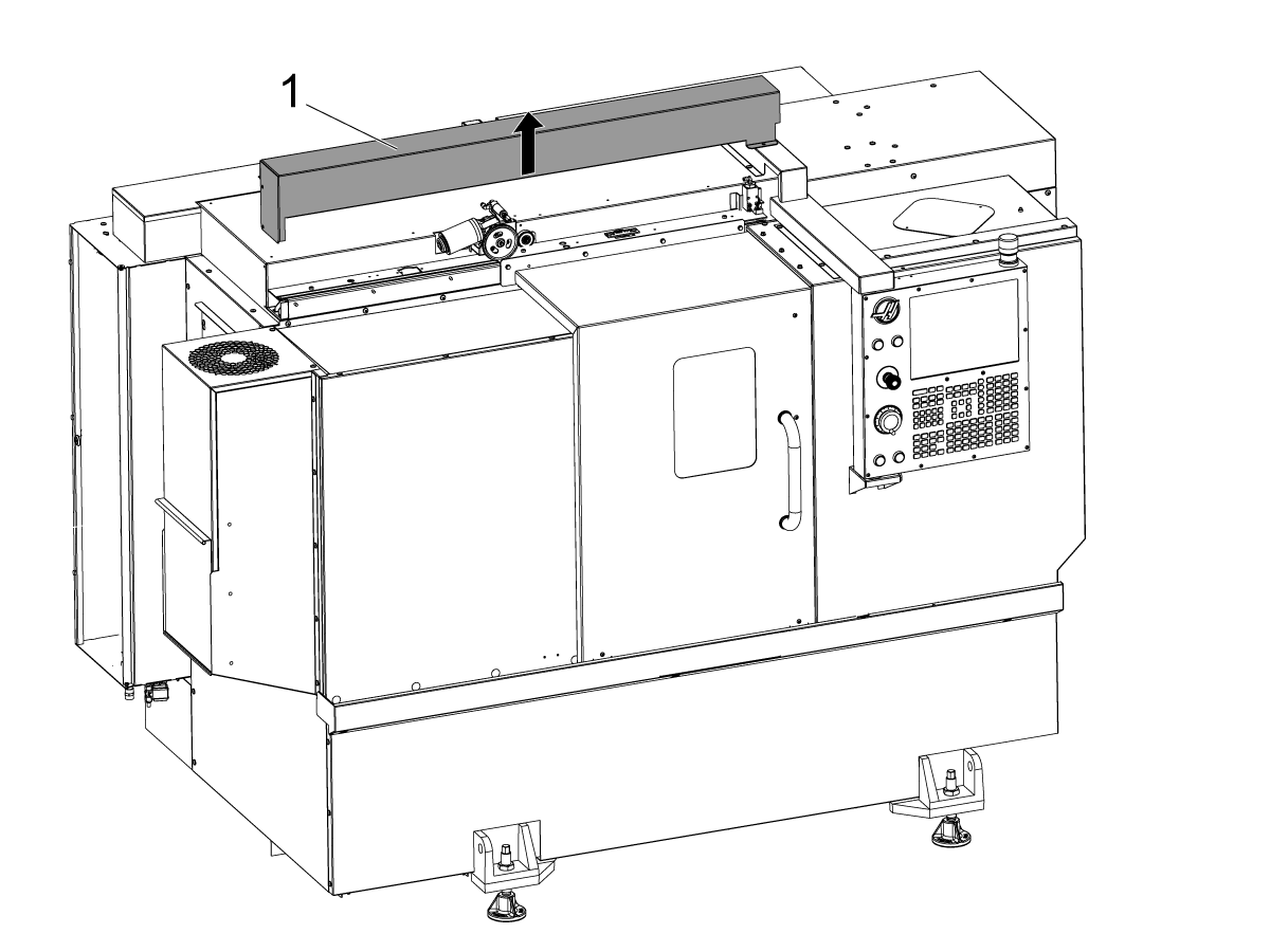
    Ta bort autodörrens kåpa [1].

    2

    ST-20/25 och DS-20Y/25Y:

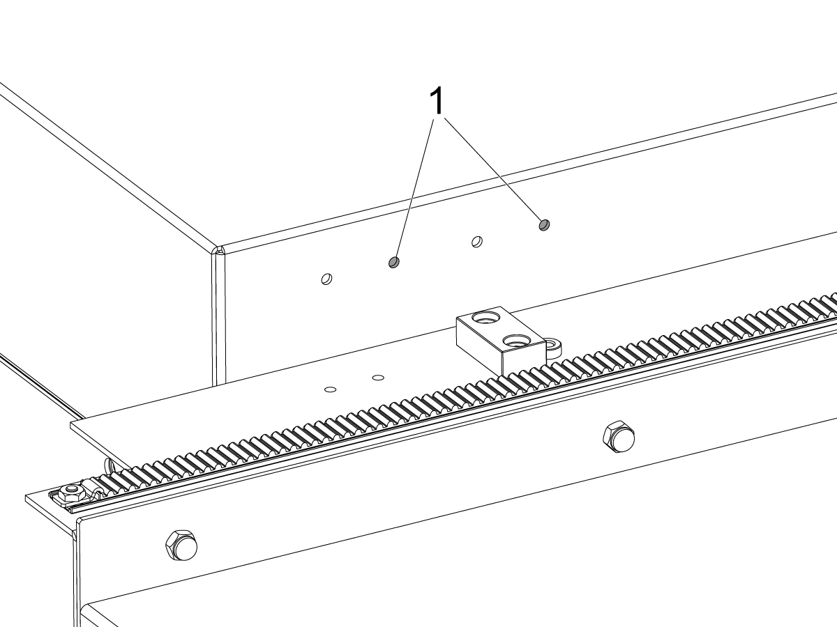
    På maskiner med brytarfästets hål på takpanelen. Montera brytarfästet i det högra hål[1]paret på ST-20/25.

    3

    På maskiner med brytarfästets hål på takpanelen.

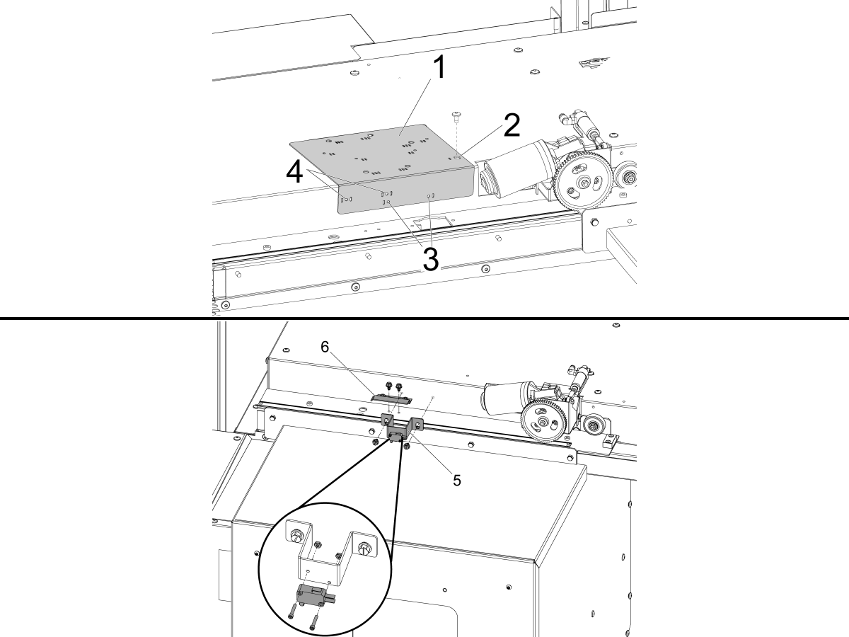
    Använd den medföljande borrledaren [1] för att borra monteringshålen till statusomkopplaren.

    Rikta in den högra delen av hålet ovanpå borr ledaren som är märkt med ett fack [2] med autoluckans monteringshål till vänster om den automatiska dörrens motor och fäst den med BHCS-enheten.

    ST-10/15:

    • Borra de två Ø 4,7 mm (3/16") monteringshålen genom borrmallens hål som är markerade med ett spår [3].

    ST-20/25 och DS-20Y/25Y:

    • Borra de två Ø 4,7 mm (3/16") monteringshålen genom borrmallens hål som är markerade med två spår på båda sidor [4].

    Använd medföljande självgängande skruvar och montera DOOR FULLY OPEN säkringsboxen [5] och DOOR FULLY OPEN utlösningsflaggan [6].

    4

    Koppla in brytaren DOOR FULL OPEN enligt märkning:

    • BLK till den övre anslutningen [1].
    • RED till mittanslutningen [2].

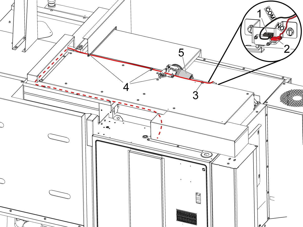
    Sätt kabeln i kopplingsskåpet så som bilden visar.

    ANM.: Använd medföljande magnetklämma [3] och kabelklämmor [4] så att kabeln hålls fri från dörrmotorns rörelse [5].

    5

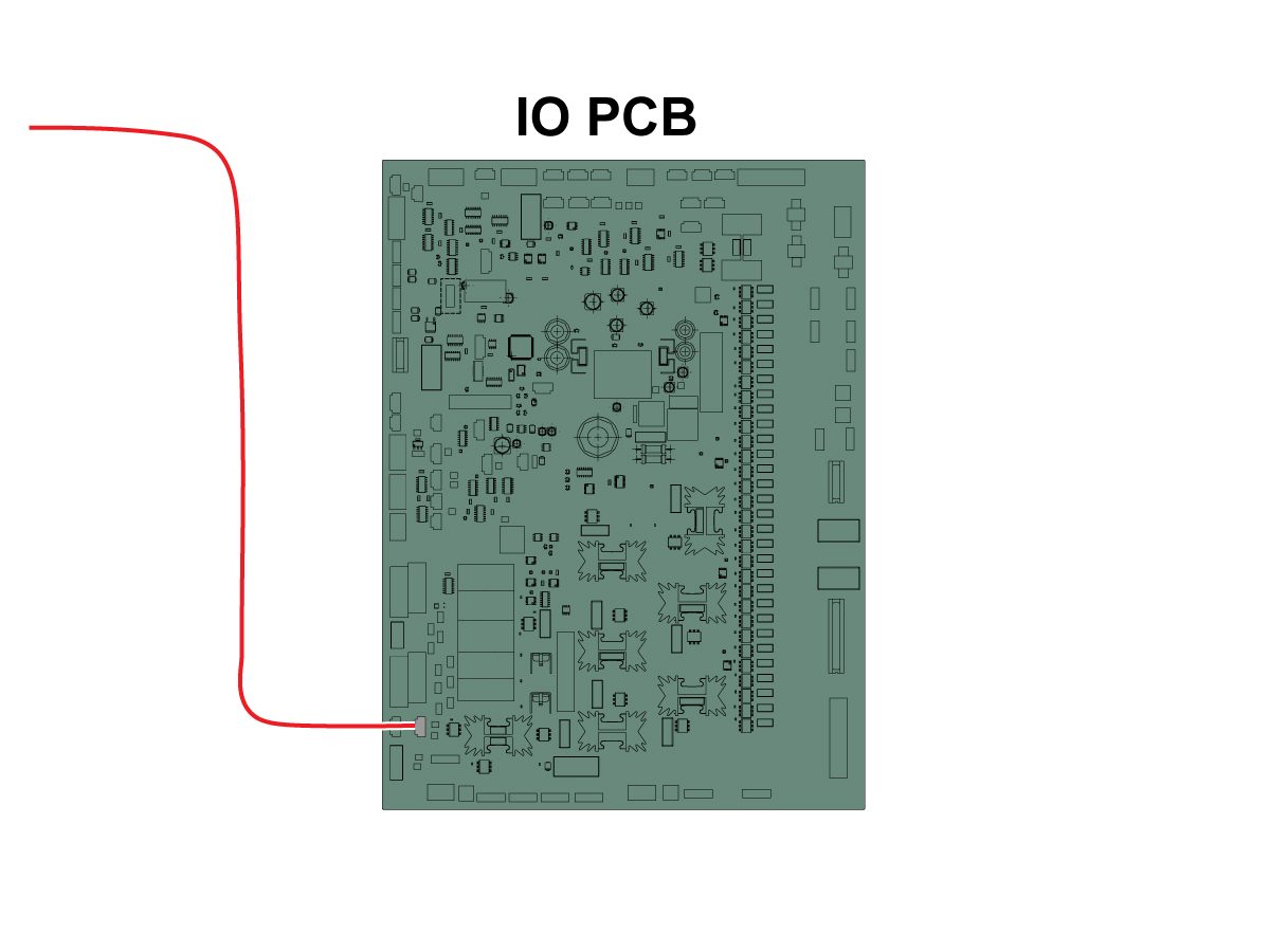
    Anslut kabelns andra ände till ingången SIO PCB P27 RRI Dörr öppen inmatning. 

    ANM.: Kontrollera att maskinen är AVSTÄNGD. 

    Installera autodoor locket.

    6

    • Fjädermataren görs med ett skaft för att passa antingen en 25mm eller 1 tum verktygshållare
    • Detta verktyg måste ta upp en verktygshållare på revolvern
    • Om maskinen är en ST-10/15 behöver du två tomma verktygshållare för att ge tillräckligt med utrymme för griparen
    • Inled allaprogram med följande programsteg för att säkerställa att detaljen sitter rätt i chucken:
      • Lokalisera fjäder Pusher framför delen
      • Flytta Z-axeln för att komprimera våren om 0,50 inches eller 12,7 mm
      • Öppna chucken med en Dwell på en sekund
      • Stäng chucken med en Dwell på en sekund
      • Dra tillbaka revolvern till säkrast möjliga position

    Obs! Artikelnumret för fjädermataren är: 

    • 30-12642 FJÄDERINMATARE  Hållaren på 25 mm (1,0”) säljs separat.

    Cobot Installation

    1

    Kontrollera att Cobot och dess styrbox är från samma matchande uppsättning med matchande serienummer.

    Det finns en vit dekal med Haas serienummer [1]. Se till att dessa är desamma på båda rutorna.

    Det finns en gul cirkeldekal med ett identifieringsnummer [2]. Se till att dessa är desamma på båda rutorna.

    2

    Mät detta avstånd från maskinkjolen till stativets sida.

     Anm.: Följande mått är rekommenderade avstånd. Positionen kan variera beroende på användarens applikation. 

    Använd måtten i nästa steg som referens för front- och sidladdningscobotar. 

    Haas Cobot10 bör installeras tillsammans med Haas Cobot-stativet. Denna piedestal är konfigurerad för att vara tillräckligt stabil när den används i enlighet med Haas definierade gränser för detaljstorlek och vikt. 

    3

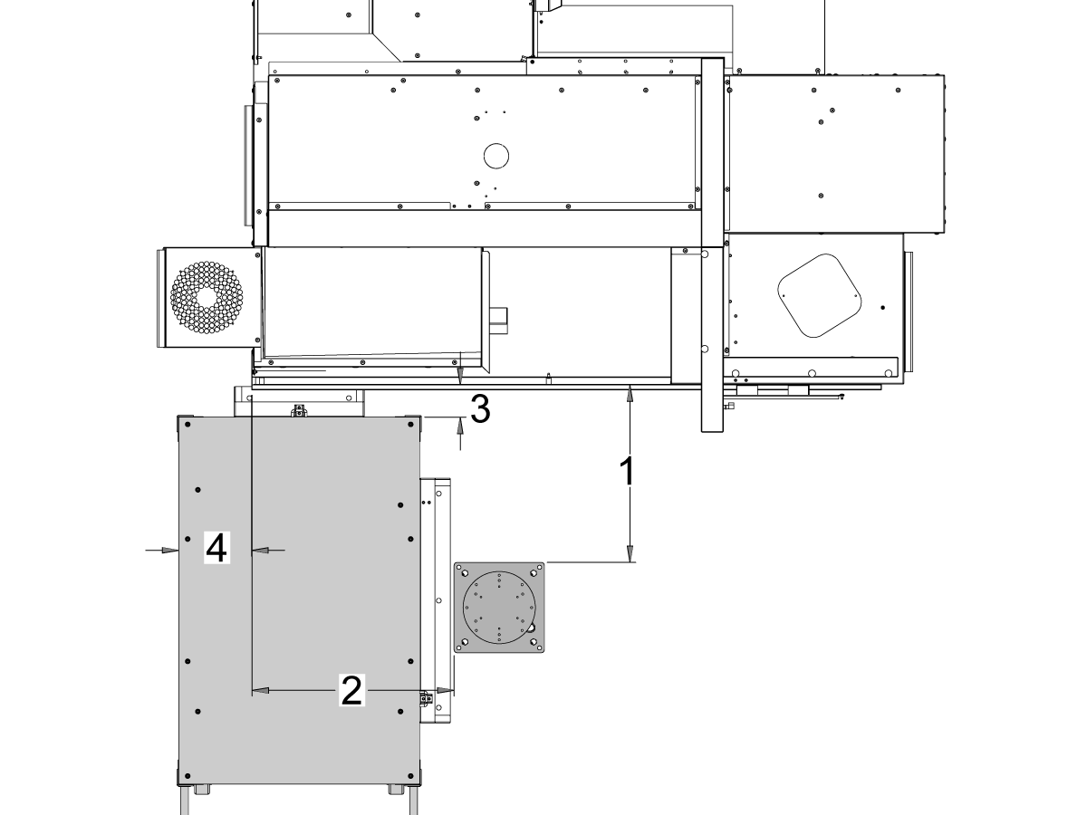
    ST-10- och ST-15-maskiner:

    Placera stativet och detaljtabellen på följande plats i förhållande till maskin:

    Mått Tumbaserad (tum) Metrisk (cm)
    Från maskinens framsida till stativets framsida [1] 24,5" 62,2 cm
    Från maskinens vänstra sida till vänster sida av stativet [2] 26,25" 66,7 cm
    Från maskinens framsida till detaljbordets framsida [4] 5,5" 14 cm
    Från maskinens vänstra sida till detaljbordets vänstra sida [4] 9,75" 24,7 cm

    4

    Updated

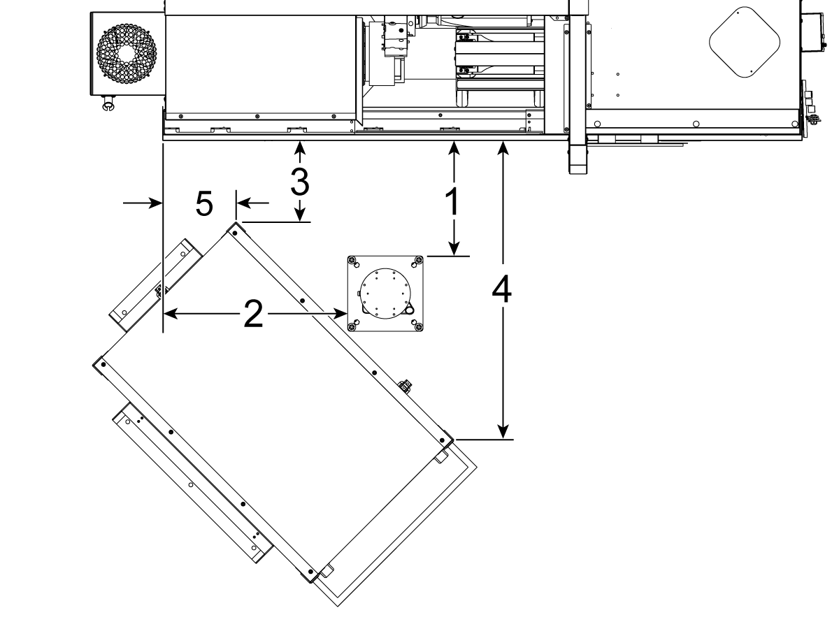
    ST-20 och ST-25-maskiner samt DS-20Y/25Y:

    Placera stativet och detaljtabellen på följande plats i förhållande till maskin:

    Mått Tumbaserad (tum) Metrisk (cm)
    Från maskinens framsida till stativets framsida [1] 19,5" 49,5 cm
    Från maskinens vänstra sida till vänster sida av stativet [2] 28,5" 72,4 cm
    Från maskinens front till främre vänstra hörnet av detaljbordet [3] 14,5" 36,8 cm
    Fram på maskinen till främre högra hörnet av detaljbordet [4] 71" 180 cm
    Från vänster sida av maskinen till främre vänstra hörnet av detaljbordet [5] 10,75" 27,3 cm

    5

    ST-30/35- och DS-30Y-maskiner:

    Placera stativet, detaljtabellen och cobotstyrboxen[5] på följande plats i förhållande till maskinen:

    Mått Tumbaserad (tum) Metrisk (cm)
    Från maskinens framsida till stativets framsida [1] 8,5 tum 21,6 cm
    Från maskinens vänstra sida till vänster sida av stativet [2] 42,0 tum 106,7 cm
    Från maskinens vänstra sida till detaljbordets vänstra sida [3] 23,5 tum 59,7 cm
    Från maskinens framsida till detaljbordets framsida [4] 24,0 tum 61,0 cm

    6

    Förankra stativet i underlaget. Rikta stativet med vattenpass. 

     Observera: För den justerbara stativet, Ställ in önskad höjd genom att lossa ställskruvarna [1] och justera sedan gaffelpinnen [2]. Dra åt ställskruvarna [1] innan du installerar roboten. Placera en bubbelnivå på toppen av stativet medan du använder (x4) hex bultar vid basen för att ställa in nivån i X och Y-planet.

    Placera cobotstyrboxen [3] intill stativet för att säkerställa tillräckligt kabelslack. 

    7

    Ta bort roboten från transportlådan. 

     ANM.: Montera adapterplattan mellan stativet och roboten vid behov. 

    Montera coboten på stativet.

     Observera: Se till att cobot-kabelkontakten [1] är vinkelrät mot maskinens framsida. 

    VIKTIGT:  Coboten väger ca 40 lbs och måste lyftas med hjälpmedel med lämplig kapacitet.

    Ta bort robotens lyftfästen och skruvar efter installation av roboten.

    8

    Inuti Cobot-förpackningen finns en liten påse [1] med reservdelar, inklusive: 

    • Säkring
    • Skruvar (2)
    • Styrboxens knappar

    Det finns en medium påse [2] fylld med en extra M12-kontakt. Denna kabel kan användas för att konfigurera in- och utgångar för I/O-slutmodulen. 

    Det finns en stor påse [3] fylld med papper och ett USB-minne som laddas ner med Cobot-programvaran.

    Förvara dessa reservdelar på en säker plats för framtida behov. 

    Robot Electrical & Air - Installation

     DANGER: Working with the electrical services required for CNC machines is extremely hazardous and can result in serious injury or death.

    Before connecting line wires to the CNC:

    • Turn off all power to the machine at the source.
    • Perform a Lockout-Tagout (LOTO) procedure to ensure the power remains off during service.
    • Verify that power has been disconnected by using an AC voltage detector on all incoming lines.

    If you are uncertain about how to safely disconnect power or perform LOTO procedures:

    • Do not proceed.
    • Contact qualified personnel or obtain appropriate assistance before continuing.

    Failure to follow these precautions may result in electrical shock, equipment damage, or fatal injury.

     Danger: Before beginning any work inside the control cabinet, verify that the High Voltage indicator light on the 320V Power Supply / Vector Drive has been off for a minimum of five (5) minutes. This waiting period ensures that residual voltage has dissipated and reduces the risk of electric shock.

    Certain service procedures involve high-risk electrical components and may pose serious injury or fatality hazards. Technicians must not attempt any procedure unless they have a complete understanding of the steps involved and the associated risks.

    If there is any uncertainty regarding a procedure, contact your Haas Factory Outlet (HFO) to arrange for a qualified service technician.

    1

    Connect Interface Box to Haas Machine:

    The robot safety devices interface box 32-9018 has magnetic mounts to attach to the machine sheet metal. Mount the interface box [1] as shown in the picture.

    Route the interface electrical cables [2] along the enclosure with the magnetic mounts and zipties. Route the cable through the bottom of the electrical cabinet.

    NOTE: For information on upgrading the interface box to the Robot Safety Devices Interface Box, refer to the Robot Safety Devices Interface Box - Installation - AD0703. 

    2

    Connect Interface Box to Haas Control Cabinet:

    Connect cable 33-8562C E-STOP terminal block to TB-1B [1] and connect the Setup mode terminal block to TB-3B [1] on the SIO PCB.  

    Plug the user relay into K9 and K10 [2].

    Verify the jumper is installed on the SIO PCB at JP1.

    Connect the pigtail cable labeled P1 SIO to the SIO PCB at P1 [3]

    NOTE: If the machine has a Regen Vector Drive, unplug cable 33-0634 FILTER OV TO IOPCB P1 from P1 SIO and plug it into the connector FILTER OV FAULT on cable 33-8562C. If the machine does not have a Regen Vector Drive, do not plug anything into the connector FILTER OV FAULT.

    Connect the RJ-45 cable [4] to Ethernet to USB adapter [5] (33-0636).  Connect the USB connector end to the Maincon PCB J8 top port. Add a ferrite filter [6] to the USB adapter.

    Mount the 24VDC Power Supply [7] to the left side of the control cabinet and plug into connector labeled 24V PS on cable 33-8562C. Connect cable 33-1281 [8] to the 24VDC Power Supply [7] and plug into P3 on the PSUP PCB. 

    3

    For MM/SMM CM/CL machines Without XMR

    If P3 is occupied by a jumper connected from P3 [10] to P7 [9] on the PSUP PCB, a splitter cable is needed to allow the 24VDC power supply [7] to be connected to the 120VAC connectors on the PSUP. Connect the male connector of the splitter cable to P3 [10] and then connect the jumper from that cable to P7 [9] and also cable 33-1281 [8].

    Note: Make sure that the jumper cable is connected where the red lines up with the red from the splitter cable.

    4

    Inside the Cobot control box, install part of the robot signals cable (33-1272 or 33-1351).  To do so, remove the safety connector [1] from the Cobot control box in order to install the different colored wires into their respective location

    33-1272 / 33-1351 cables [2] going to safety connector:

    • Gray wire to top 24V
    • Red wire to bottom 24V
    • Green wire to EI0
    • Brown wire to EI1
    • Jumper [3] from SA0 to SA1
    • Jumper  [4] from SB0 to SB1

     NOTE: The rest of the wires from this cable are not used. Put some electrical tape on each wire lead and Ziptie the leftover unused wires. 

    5

    Important: After installing all the cables from the robot signal cable, make sure that the fuse [1] remains installed at all times to protect the Cobot control box.

    6

    Connect Cobot to the Interface Box:

    Connect the RJ45 ethernet cable [1] from the Cobot Control Box to the interface box. Add a ferrite filter [2] to the RJ-45 cable.

    Connect the robot signals cable [3] from the Cobot Control Box to the interface box. 

    Connect the 120 VAC Cobot Power Cable [4] to the external power source. 

    Connect the robot power cable [5] from the control box to the Cobot.

    Connect the teach pendant cable [6] from the control box to the teach pendant. 

    NOTE: For more information regarding interlock fence, area scanner or light curtain installation, refer to the Robot Safety Device section below.

    7

    Make sure the Remote Jog Handle is installed onto the machine.

    NOTE: For more information on the RJH-XL installation, refer to Remote Job Handle - Touch Large (RJH-XL) - Installation - AD0533. 

    8

    Steps 7 thru 10 are wiring and hose routing instructions for the pneumatic grippers. Refer to the grippers installation section lower on this page for the mechanical installation.

    Install the dual air solenoid assembly on to the side of the pedestal while giving the airlines enough slack. Make sure it's in a position where it will not be in the way. Route the airline [1] under the machine back towards the CALM cabinet as shown.

    9

    Inside the CALM cabinet, remove a plug from one of the CALM manifold ports and install the check valve [1] (58-1863) onto the port's fitting. Route the input airline [2] from the dual air solenoid assembly (from previous step) into the CALM cabinet and connect the airline to the check valve.

    Turn the machine air supply ON.

    10

    Make sure to power OFF the control box [1].

    Connect the solenoid cable from the dual air solenoid assembly [2] into the Digital Output on the Cobot control box [1]. Remove the connector from Cobot control box.

    11

    Connect the gripper solenoid power cable (33-1276 / 33-1341) to the Digital Output terminal inside the control box. Install the different colored wires into their respective location:

    • Black/white cable into 0V
    • Black cable into DO0
    • Orange/white cable into 0V
    • Orange cable into DO1
    • Red/white cable into 0V
    • Red cable into DO2
    • Brown/white cable into 0V
    • Brown cable into DO3

    Power ON the control box.

    Robot Safety Device

    VIKTIGT: ANVÄND INTE ROBOTEN FÖRRÄN DU HAR KONFIGURERAT OCH TESTAT KORREKT FUNKTION FÖR SKYDDSUTRUSTNINGEN.

    Ljusridå

    Cobot-paket levereras med ljusridåsändaren och mottagaren som standardsäkerhetsenhet. Följ proceduren nedan vid installation av ljusgardiner: 

    Installera ljusridå

    ANM.: Om områdesskannern eller satsen HC10 förberedd maskin har beställts kommer det också att finnas en 1M ljusridåmottagare och sändare. Dessa levereras med alla Cobotar. 

    Robotstängsel:

    Om maskinen levererades med stängseltillval måste robotstängslet och grindlåsenheten installeras på maskinen. Följ proceduren nedan vid installation:

    Installation av skyddsstängsel för robot

    När stängslet har monterats ska stängselpanelen monteras mellan maskinen och robotstängslet.

    Områdesskanner

    Om maskinen har levererats med områdesskanner som tillval måste områdesskannern installeras och konfigureras för utrymmet. Följ proceduren nedan vid installation: 

    Installation av områdesläsare

    First Power-UP

    1

    Power ON the Haas machine. 

    Power ON the Cobot by flipping the power switch [1].

    Power ON the Cobot teach pendant by pressing the circle [2]. 

    Make sure that E-STOP [3] on the Cobot teach pendant is released. 

    In order to change the language, click on the language drop down menu. Choose EN for English. To confirm this setting change, the Cobot teach pendant will have a popup asking to insert the username & password. 

    Enter "admin" for both the username and password. 

    2

    Note: The Cobot teach pendant will have a popup asking to insert the username & password. To sign into the teach pendant use these credentials:

    • Username = admin
    • Password = admin

    Go into Run mode. Press Enable. 

    Go into Jog mode [1].

    Move each joint to it's zero location with the Move Zero buttons [2]. 

    3

    Once the robot is in it's zero location, verify that the hash lines [1] align on either side of each joint on the Cobot. 

     IMPORTANT: If any joint hash lines [1] do not align, jog the specific joint accordingly until all the hash lines [1] do align. This position will be set in the next step as the new Cobot zero position.  

    Connect an ethernet cable [2] from the Cobot control box into a computer.

    On the computer, change the adapter setting to enable the ethernet port. 

    Note: See next steps for help on changing adapter settings.

    4

    To change the adapter settings, open the settings page [1] on the computer, then click on Network & Internet [2] which will bring up the network status page.

    Click on Change adapter options [3] then right click on Ethernet [4] and open up the properties window [5]. From there select the Internet Protocol Version 4 (TCP/IPv4) [6] option and click Ok. 


    5

    The ethernet settings will now be correct. Open a web browser window and type in the IP address of the Cobot[1]. 

    Note: This is the same process as connecting a laptop to an HRP-1/2/3. For more information on connecting to the Cobot via ethernet, refer to the video on the HRP-Troubleshooting page that is in the Connect & Jog Haas Robot section. 
    6

    Download HRTool through HBC. On the Service section of HBC, navigate to Utilities > Documents and Software > 01 Control Software > 01 Next Generation Control > 10 Cobot Software > HRTool.zip.

    Unzip the folder and navigate to HRToolsMaind.exe.

    Insert the Cobot IP address found under the Systems tab.  Click Set. 

    Go to the Config tab on HRTool.

    Click "get" to see the actual vs. theoretical encoder values. 

    Click "set" to set the theoretical to the actual encoder values. This step sets the Cobot's current position as it's new home position. 

    7

    Make sure that each joint's actual and theoretical encoder values match. 

    NOTE: If the valuyes do not match, press "Set" again. 

    8

    On the teach pendant, navigate to System [1] and then Update System. 

    Confirm the Cobot firmware [2] is either:

    • HR5.51H.16.beta.20231213.zip
    • HR6.4.9.tmp.20240919.zip

    NOTE: Firmware version HR6.4.9.tmp.20240919.zip is compatible with all size cobots.

    Refer to the Haas Cobot - Maintenance chapter for the firmware update procedure. 

    9

    Turn on the Haas CNC.

    Zero Return all Axes.

    Insert Service USB key.  Go into Service mode.

    Go to Parameters> Factory tab.  Change the following:

    • 1278 [1278:] Robot Ready E-Stop Enabled to TRUE
    • 2191 [694:] LIGHT CUTAIN TYPE to LC_TYPE_1
    • 2194 [:] Enable Front Door Fully Open Switch to TRUE

    Note: Machines with Software Version 100.20.000.1010 or higher will need to change the following parameter:

    • 2192 [:] Light Curtain Trigger Threshold to 0

    Press [SETTING].

    Set the Settings:

    • 372 Parts Loader Type to 3: Robot.
    • 376 Light Curtain Enabled to On


    10

    On the Haas pendant, press [CURRENT COMMANDS].

    Go to Devices>Robot>Jogging tab. Change the following:

    • Maximum Jogging Speed to 7.9 inch/sec

     Note: The jogging increments on the RJH are a percentage of this max speed value. In order to decrease the distance the robot travels of each jog wheel tick, you need to change your Maximum Jogging Speed to a lower value.

    Go to the Setup tab. Change the following:

    • Max Robot Speed to 118 in/sec (2000 mm/sec). 
    • Enter the Net Mass of the gripper. Refer to the layout drawings on our website (Single Gripper layout drawing OR Dual Gripper layout drawing) to get the correct value for this setting
    WARNING: Setting this value incorrectly can cause the Robot Arm to not move correctly. 
     
    • Number of Grippers to the number of grippers.
    • Raw Gripper Clamp Output to 1.
    • Raw Gripper Unclamp Output to 2.
    • Raw Gripper Clamp Delay to the clamp/unclamp duration in sec.
    • Raw Gripper Clamp Type to OD/ID.
    • Finish Gripper Clamp Output to 3.
    • Finish Gripper Unclamp Output to 4.
    • Finish Gripper Clamp Delay to the clamp/unclamp duration in sec.
    • Raw Gripper Clamp Type to OD/ID.

    Security Risk Level

    1

    IMPORTANT: Make sure to perform an appropriate risk-assessment and met all appropriate safety requirements. 

    2

    Based off the risk assessment, set the appropriate security risk level on the Cobot teach pendant. Navigate to Config > General Restrictions and tap of the desired security risk level [1] from 0 - 5.

    Use the  "admin" code in the safety verification to change the security level.

    NOTE: When the security risk level is lower, the robot will have a lower maximum speed, force, etc. When the security risk level is higher, the robot will have a higher maximum speed, force, etc. 

    This security risk level will calculate the maximum allowable force, speed, power, momentum, elbow speed and elbow force [2] that the Cobot will withstand before Alarm 9150.10017 Collison Stop Error is triggered. 

    IMPORTANT: The robot's programmed speed cannot be greater than the allowable speed from the security risk level. 

    NOTE: For more information regarding alarms, refer to the Haas Cobot - Troubleshooting Guide. 

    Activation

    1

    Download and load the configuration files by logging into the HAAS SERVICE PORTAL.

    Download the safety automation option front/side configuration files.

    Load the option configuration patch file to the control. Refer to the NEXT GENERATION CONTROL - CONFIGURATION FILE - DOWNLOAD/LOAD procedure.

    2

    Go to Parameters > Features > Robot to verify that the robot feature has appeared on the bottom.

    3

    Press [CURRENT COMMANDS].

    Go to Devices>Robot>Setup tab [1].

    Press [E-Stop].

    Press [F1] to connect the robot[2].

    The first time connecting a robot to a machine, the robot feature will need to be unlocked. This popup shows the machine's current software version, robot mac address and a generated code. Enter this information into HBC in order to receive the unlock code.

    4

    On HBC, go to the Service tab [1].

    On the left hand side of the screen, click on Activations [2], and then select Cobot Installation [3] to begin the process to the get the Cobot unlock code.

    The first step is to enter the Machine Serial Number [4] and the Cobot Serial Number [5] in the fields on HBC.

    Once you have entered the correct information, press Next [6] in the bottom right corner and continue through the steps until you receive the unlock code.

    Note: Make sure you are on the Cobot Installation tab [3] and not the Robot Installation tab. The Robot Installation is only used for the Haas Robot Packages. Using the Robot Installation for the Haas Cobots will result in an invalid unlock code.

    5

    Enter the Cobot's Haas Serial Number[1] and the unlock code to connect the robot to the machine. 

     Note: This step can only be completed by a HFO Service Technician.

     Note: The machine needs to be activated before the Cobot is activated. Follow the Machine Activation / Time Extension - NGC procedure.

    When the robot has connected with the machine, a yellow message saying Robot Activation Successful should appear at the bottom of the Haas screen.

    6

    Release the [E-STOP] and press RESET to clear the alarms. 

    Press the [HANDLE JOG] button. 

    Press the [CURRENT COMMANDS]  and go to Devices > Robot > Jogging tab.

     Note: The robot in setup mode can only be handle jogged while the F2 button the RJH is pressed. See Setup/Run mode section below.

    On the Remote Handle Jog Touch press the Joint button to go into the Joints Coordinates.

    Move the robot to an accessible location to install the grippers.

    Jog J6 to 0.0000 position. The location hole should be centered on top.

    Note: Press [E-STOP] before working on the robot.

    Gripper Installation

    1

    Turn off the machine air by turning the valve in the Air/Lube cabinet and pull the pressure relief valve to release the air in the system.

    2

    For the Dual Action Gripper:

    There are two versions of the dual-action grippers for this section, both of which have the same installation process.

    Jog the robot so that the location hole [1] is centered on top.

    Install the adapter plate [2] onto the end of the robot arm.

    Install the dual gripper assembly [3] onto the adapter plate [2].

    NOTE: Make sure to install Gripper 1 (which has the orange and purple zip ties) onto the Gripper 1 adapter plate section. 

    3

    For the Angled Single Action Gripper:

    Jog the robot so that the location hole [1] should be centered on top.

    Install the angle adapter plate [2] to the end of the robot arm.

    Install the single gripper assembly [3] onto the angle adapter plate [2]. 

    4

    To install the bar gripper fingers, remove the slug gripper plates from the gripper bodies.

    Install the Bar Gripper Bolt Plates [3] with (x8) SHCS M6 screws [4]. Torque to 10 ft-lbs.

    Install the Bar Gripper Fingers [2] with (x8) SHCS 1/4-20 [1]. Torque to 13 ft-lbs.

    5

    Configure the dual air solenoid assembly used for pneumatic grippers depending on single [1] or dual [2] gripper configuration. 

    For single grippers [1], connect the incoming air to the to the fitting [2] and keep the plug in the other end of the fitting [3] as shown in the image.

    For dual grippers [4], remove the plug in the fitting [3] and attach a small air hose to the second solenoid [5]. Then connect the incoming air hose to the fitting [2] so that both solenoids are receiving air.

    6

    For the Single Gripper:

    Route the (x2) air lines from the gripper to the same color coded fitting on the dual air solenoid assembly. 

    Secure the air lines by wrapping them in cable conduit. Use the velcro straps to attach the cable conduit to the Cobot. Make sure there is enough slack so that cables aren't strained when Cobot is fully extended.

    Insert the input air hose to the used solenoid's fitting [1]. 

    Make sure the plug is installed onto the unused solenoid's fitting [2]. 

    7

    For the Dual Gripper:

    Route the (x2) air lines from gripper #1 to the same color coded fitting on the dual air solenoid assembly. 

    Route the (x2) air lines from gripper #2 to the same color coded fitting on the dual air solenoid assembly. 

    Secure the air lines by wrapping them in cable conduit. Use the velcro straps to attach the cable conduit to the Cobot. Make sure there is enough slack so that cables aren't strained when Cobot is fully extended.

    Insert the short airline [1] connecting the first solenoid with the second. 

    Insert the input air hose to the fitting [2]. 

    Parts Table Assembly

    If the parts table option was ordered, follow the procedure below for assembly instructions:

    Haas Robot - Parts Table Assembly

    NOTE: If HC10 MACHINE READY KIT was purchased, there is no need to install the wheels if mounting the parts table directly into the wooden pallet. 

    Verification

    Test the E-stop:

    • Press each E-STOP button located on the Haas Pendant, RJH-XL, and Cobot Teach Pendant. Make sure the machine generates 107 EMERGENCY STOP alarm.  If the E-STOP button does not generate a 107 EMERGENCY STOP alarm verify the wiring. Load the latest configuration files to enable the RJH-XL.

    Test the Robot Safety Device:

    Make sure that there is an E-STOP or light curtain triggered icon on the Haas pendant when the robot safety device is triggered. 

    • Fence - Insert the key into the interlock, verify that the two red LED lights in the front of the interlock are OFF. Remove the key from the interlock, verify that the two red LED lights are ON. 
    • Area Scanner - Step inside the protective field, verify that the red LED lights up on the area scanner. Step outside the protective field, verify that the green LED lights up.
    • Light Curtain - Interfere the light curtain beams, verify that the light curtain triggered icon appears on the Haas pendant. Press [RESET]. Step outside of the light curtain beams, verify no icon appears on the Haas pendant. 

    NOTE: If the light curtain triggered icon does not show, verify wiring, alignment and factory setting: 2191 [694:] LIGHT CURTAIN TYPE is set to LC_TYPE_1.

    Test the Operation of the Grippers:

    • Verify that both grippers clamp and unclamp correctly.
    • Press the [CURRENT COMMANDS]  and go to Devices > Robot > Jogging tab.
    • Press [F2] to clamp/unclamp the Finish Gripper.
    • Press [F3] to clamp/unclamp the Raw Gripper.

    Test the Remote Jog Handle:

    • Undock the Remote Jog Handle
    • Press the [HANDLE JOG] button. 
    • Press the [CURRENT COMMANDS]  and go to Devices > Robot > Jogging tab.
    • On the Remote Handle Jog press the Joint button to go into the Joints Coordinates.
    • Move the robot to a safe location.

    IMPORTANT: If a yellow warning message appears saying "Please activate Light Curtain or Cell Safe" while trying to job the robot, verify the safety parameter was applied by re-uploading the configuration files from HBC. 

    Verify Safe / Run Mode Operation

    All Haas CNC machines are equipped with a key switch on the side of the control pendant to lock and unlock setup mode. The robot will have the following behaviors depending on what mode is selected. 

    • When the Haas control is in Run mode, mode 1, triggering the robot safety device stops all motion. This motion can not be started until the robot safety device is no longer triggered.
    • When the Haas control is in Set up mode, mode 2, speed limited motion such as jogging an axis of the robot can be performed in order to program a robot's path of motion, pick up position, set a robot's tool center point, (an offset), load and pick up parts from the spindle or part holder in the machine, etc. The programmed path will also be able to be run slowly to prove out the programmed path of the robot. The robot in setup mode can only be handle jogged while the F2 button the RJH is pressed.

    Haas Robot - Quick Start Guide

    När roboten har installerats ställs ett jobb in enligt följande procedur.

    Haas Robot – Snabbstartsguide

    Disable the Robot

    Avaktivera roboten för att köra maskinen i fristående läge. Tryck på [SETTING] (inställning). Ändra följande inställningar:

    • 372 – Typ av detaljladdare på0: Ingen
    • 376 – Aktiverad ljusridå på PÅ


    5.3 Installation DM/DT/MM/DC-1/UMC-350 Installation

    Recently Updated

    Haas Cobot 10 (HC10) – DM/DT/MM/DC-1/UMC-350 - Installation


    AD0716

    Revidering D – 11/2025

    Introduction

    Updated

    Den här proceduren används för att installera Haas 10 KG Cobot (HC10).

    Obs! Haas konstruerade arbetscell som består av en CNC machine och en robot har utvärderats för överensstämmelse med CE-krav. Ändringar eller variationer i Haas-cellens utformning ska utvärderas avseende överensstämmelse med tillämpliga standarder och är användarens/integratorns ansvar.

    Maskinkrav:

      Programvaruversion från 
    • 100.24.000.1001
    • HR5.51H.16.beta.20231213.zip-version eller HR6.4.9.tmp20240919.zip version.
    • DT/DM/MM/SMM/DC-1/UMC-350 Tillverkade efter datum: (se maskinkrav i respektive procedur) 
      • Haas autodörr 
      • Haas Auto-fönster
         Observera:  MM/SMM, DM-3, DT-3 och DC-1 är endast tillgängliga för sido laddnings alternativet (93-1001053).
      • Obs! MM/SMM-maskiner utan transformator kräver en delningskabel som måste beställas för att cobotar ska kunna monteras hos kunden. Splitterkabeln kan beställas med art.nr. 93-5067.
    • 34-349xB I/O-kort eller senare
    • 93-1000610 HANDRATT TOUCH LCD (RJH-XL) RHANDRATT - XL  

    Verktygskrav:

    • Flat liten skruvmejsel

    Fixing / Anchoring Requirements

    • The Haas 10KG Cobot (HC10) is configured and sold by Haas with a pedestal/table that is sufficiently stable when used according to Haas defined part size and weight limits. 
    IMPORTANT:  For more information directly on the Hans Cobot, refer to the Hans Robot Operation Manual for Elfin Software.

    There are 3 scenarios in which the cobot option can be installed on a Haas machine:

    1. Cobot option was ordered at the same time as the machine. Both the cobot and the machine are being installed together.
    2. Cobot option is ordered so that it can be installed on a previously installed machine.
    3. Cobot option was previously installed on a machine, but will now be moved to a different Haas machine.

    In scenarios 2 and 3, additional parts will need to be ordered under the Serial Number of the Haas machine. See the tables below for what parts are needed in the different scenarios.

    Scenario 1 - Cobot and Machine are ordered and installed together

    Component Part Number Description
    NO ADDITIONAL PARTS NEED TO BE ORDERED WHEN COBOT AND MACHINE ARE ORDERED TOGETHER

    Scenario 2 - Cobot being field installed on existing Haas Machine

    Component Part Number Description
    CHECK TO SEE IF HAAS MACHINE ALREADY HAS THESE FEATURES & PARAMETERS BEFORE ORDERING
    Robot Feature Unlock Parameter 93-1001031 Kit activates the robot feature on the Haas machine. To check if you need this kit, go to the Features tab on the Haas Control and check if the Robot option is highlighted. This kit does not include any physical parts.
    Load Type Safety Parameters 93-1000997 Front Automation Safety Parameters - Kit is needed when the cobot will be loading parts through the front door of the Haas machine. This kit does not include any physical parts and the autodoor option would need to be purchased and installed separately.
    OR  
    93-1000996 Side Automation Safetly Parameters - Kit is needed when the cobot will be loading parts through the side window of the Haas machine. This kit does not include any physical parts and the autowindow option would need to be purchased and installed separately.

    Scenario 3 - Cobot is being transferred from one machine to a different Haas Machine

    Component Part Number Description
    Cobot Integration Kit See Integration Kit Compatibility Chart Kit is needed to install parts on the Haas machine to interface with the cobot. This includes the interface box, door switches, etc... as well as the Robot Unlock Feature parameter. This kit only needs to be purchased when transferring a cobot to a new Haas machine since these parts are normally included when a cobot is ordered. 
    Load Type Safety Parameters 93-1000997 Front Automation Safety Parameters - Kit is needed when the cobot will be loading parts through the front door of the Haas machine. This kit does not include any physical parts and the autodoor option would need to be purchased and installed separately.
    OR  
    93-1000996 Side Automation Safetly Parameters - Kit is needed when the cobot will be loading parts through the side window of the Haas machine. This kit does not include any physical parts and the autowindow option would need to be purchased and installed separately.
    Safety Device 08-1899 Multi-Sided Light Curtain Kit - Kit is needed if the safety device is NOT going to be transferred from the first machine and the second Haas machine needs it's own safety device. This kit makes a 4-sided protective barrier.
    OR  
    08-1948 5-Sided Light Curtain Kit - Kit is needed when the safety device is NOT going to be transferred from the first machine machine and the second Haas machine needs it's own safety device. This kit makes a 5-sided protective barrier.
    OR  
    08-1987 Laser Area Scanner Kit - Kit is needed when the safety device is NOT going to be transferred from the first machine machine and the second Haas machine needs it's own safety device. This area scanner has a sensing distance of 4meters.

    Machine Setup

    1

    Robot för laddning framifrån:

    Skruva fast borrguiden [1] för närvarogivaren [2] på höljets ovansida.

    Borra och gänga (2) hål Ø10–32 genom sidan på höljet.

    • Borr storlek: #21 eller 5/32"
    • Tryck på 10-32 NF

    Ta bort borrguiden [1]. 

    Montera dörren öppen närvarogivaren [2] på hålen i höljet.

    Slå på närvarogivaren för att hitta önskad utlösningsflagga [3] på dörren. När utlösningsflaggan [3] är i ett bra läge för att utlösa närhetssensorn, markera hålpositionen. 

    Montera utlösningsflaggan [3] med självgängande skruvar på sidan av dörren. 

    Dra kablarna för helt öppen dörr in i styrskåpet enligt bild.

    Anslut närvarogivarens kabel till  SIO PCB P27. 

    2

    Robot för laddning från sidan:

    Ta bort locket [1] och dess skruvar [2] för att exponera luftcylindern [4] i det automatiska fönstret. Höj luftcylindern [4] så att fästena [3] och luftcylindern är fästa enligt bilden.

    Anslut de medföljande grå och gula luftledningarna till autoföntrets luftcylinder - portarna på luftcylindern har grå och gula buntband som visar var varje slang ansluts.

    Montera locket [2] över luftcylindern i det autofönstret.

    3

    • Fjädermataren görs med ett skaft för att passa antingen en 25mm eller 1 tum verktygshållare
    • Detta verktyg måste ta upp en verktygshållare i verktygskarusellen.
    • Inled allaprogram med följande programsteg för att säkerställa att detaljen sitter rätt i skruvstycket:
      • Placera fjädertryckaren ovanför detaljen
      • Flytta Z-axeln för att komprimera våren om 0,50 inches eller 12,7 mm
      • Öppna skruvstycket med en sekunds fördröjning
      • Stäng skruvstycket med en sekunds fördröjning

    Anm.: Fjädertryckarens artikelnummer är: 

    • 30-12642 FJÄDERINMATARE  Hållaren på 25 mm (1,0”) säljs separat.

    Cobot Installation

    1

    Kontrollera att Cobot och dess styrbox är från samma matchande uppsättning med matchande serienummer.

    Det finns en vit dekal med Haas serienummer [1]. Se till att dessa är desamma på båda rutorna.

    Det finns en gul cirkeldekal med ett identifieringsnummer [2]. Se till att dessa är desamma på båda rutorna.

    2

    Mät detta avstånd från maskinkjolen till stativets sida.

     Anm.: Följande mått är rekommenderade avstånd. Positionen kan variera beroende på användarens applikation. Se nästa steg för positionering på coboten och detaljbordet för antingen frontlastning eller sidolastning av cobotar.

    Haas Cobot10 bör installeras tillsammans med Haas Cobot-stativet. Denna piedestal är konfigurerad för att vara tillräckligt stabil när den används i enlighet med Haas definierade gränser för detaljstorlek och vikt. 

    3

    Ladning från framsidan:

    Placera stativet och detaljtabellen på följande plats i förhållande till maskin:

    Mått Tumbaserad (tum) Metrisk (cm)
    Från maskinens framsida till stativets framsida [1] 13” 33 cm
    Från maskinens vänstra sida till vänster sida av stativet [2] 24" 61 cm
    Från maskinens front till främre vänstra hörnet av detaljbordet [3] 8" 20,3 cm
    Fram på maskinen till främre högra hörnet av detaljbordet [4] 42,25" 107 cm
    Från vänster sida av maskinen till främre vänstra hörnet av detaljbordet [5] 6,25" 15,9 cm

    4

    Laddning från sidan:

    Placera stativet och detaljtabellen på följande plats i förhållande till maskin:

    Mått Tumbaserad (tum) Metrisk (cm)
    Från maskinens framsida till vänster sida av stativet [1] 21" 53,4 cm
    Från maskinens högra sida till stativets sida [2] 13” 33 cm
    Från maskinens framsida till vänster sida av detaljbordet [3] 3" 7,6 cm
    Från höger sida av maskinen till framsidan av detaljbordet [4] 27" 68,6 cm

    5

    Förankra stativet i underlaget. Rikta stativet med vattenpass. 

    Ställ in önskad höjd genom att lossa ställskruvarna [1] och justera sedan gaffelpinnen [2]. Dra åt ställskruvarna [1] innan du installerar roboten. Placera en bubbelnivå på toppen av stativet medan du använder (x4) hex bultar vid basen för att ställa in nivån i X och Y-planet.

    Placera cobotstyrboxen [3] intill stativet för att säkerställa tillräckligt kabelslack. 

    Obs! I layouterna i föregående steg är stativhöjden 61 cm (24").

    6

    Ta bort roboten från transportlådan. 

     ANM.: Montera adapterplattan mellan stativet och roboten vid behov. 

    Montera coboten på stativet.

     Observera: Se till att cobot-kabelkontakten [1] är vinkelrät mot maskinens framsida. 

    VIKTIGT:  Coboten väger ca 40 lbs och måste lyftas med hjälpmedel med lämplig kapacitet.

    Ta bort robotens lyftfästen och skruvar efter installation av roboten.

    7

    Inuti Cobot-förpackningen finns en liten påse [1] med reservdelar, inklusive: 

    • Säkring
    • Skruvar (2)
    • Styrboxens knappar

    Det finns en medium påse [2] fylld med en extra M12-kontakt. Denna kabel kan användas för att konfigurera in- och utgångar för I/O-slutmodulen. 

    Det finns en stor påse [3] fylld med papper och ett USB-minne som laddas ner med Cobot-programvaran.

    Förvara dessa reservdelar på en säker plats för framtida behov. 

    Robot Electrical & Air - Installation

    1

    Connect Interface Box to Haas Machine:

    The robot safety devices interface box 32-9018 has magnetic mounts to attach to the machine sheet metal. Mount the interface box [1] as shown in the picture.

    Route the interface electrical cables [2] along the enclosure with the magnetic mounts and zipties. Route the cable through the bottom of the electrical cabinet.

    NOTE: For information on upgrading the interface box to the Robot Safety Devices Interface Box, refer to the Robot Safety Devices Interface Box - Installation - AD0703. 

    2

    Connect Interface Box to Haas Control Cabinet:

    Connect cable 33-8562C E-STOP terminal block to TB-1B [1] and connect the Setup mode terminal block to TB-3B [1] on the SIO PCB.  

    Plug the user relay into K9 and K10 [2].

    Verify the jumper is installed on the SIO PCB at JP1.

    Connect the pigtail cable labeled P1 SIO to the SIO PCB at P1 [3]

    NOTE: If the machine has a Regen Vector Drive, unplug cable 33-0634 FILTER OV TO IOPCB P1 from P1 SIO and plug it into the connector FILTER OV FAULT on cable 33-8562C. If the machine does not have a Regen Vector Drive, do not plug anything into the connector FILTER OV FAULT.

    Connect the RJ-45 cable [4] to Ethernet to USB adapter [5] (33-0636).  Connect the USB connector end to the Maincon PCB J8 top port. Add a ferrite filter [6] to the USB adapter.

    Mount the 24VDC Power Supply [7] to the left side of the control cabinet and plug into connector labeled 24V PS on cable 33-8562C. Connect cable 33-1281 [8] to the 24VDC Power Supply [7] and plug into P3 on the PSUP PCB. 

    3

    For MM/SMM CM/CL machines Without XMR

    If P3 is occupied by a jumper connected from P3 [10] to P7 [9] on the PSUP PCB, a splitter cable is needed to allow the 24VDC power supply [7] to be connected to the 120VAC connectors on the PSUP. Connect the male connector of the splitter cable to P3 [10] and then connect the jumper from that cable to P7 [9] and also cable 33-1281 [8].

    Note: Make sure that the jumper cable is connected where the red lines up with the red from the splitter cable.

    4

    Inside the Cobot control box, install part of the robot signals cable (33-1272 or 33-1351).  To do so, remove the safety connector [1] from the Cobot control box in order to install the different colored wires into their respective location

    33-1272 / 33-1351 cables [2] going to safety connector:

    • Gray wire to top 24V
    • Red wire to bottom 24V
    • Green wire to EI0
    • Brown wire to EI1
    • Jumper [3] from SA0 to SA1
    • Jumper  [4] from SB0 to SB1

     NOTE: The rest of the wires from this cable are not used. Put some electrical tape on each wire lead and Ziptie the leftover unused wires. 

    5

    Important: After installing all the cables from the robot signal cable, make sure that the fuse [1] remains installed at all times to protect the Cobot control box.

    6

    Connect Cobot to the Interface Box:

    Connect the RJ45 ethernet cable [1] from the Cobot Control Box to the interface box. Add a ferrite filter [2] to the RJ-45 cable.

    Connect the robot signals cable [3] from the Cobot Control Box to the interface box. 

    Connect the 120 VAC Cobot Power Cable [4] to the external power source. 

    Connect the robot power cable [5] from the control box to the Cobot.

    Connect the teach pendant cable [6] from the control box to the teach pendant. 

    NOTE: For more information regarding interlock fence, area scanner or light curtain installation, refer to the Robot Safety Device section below.

    7

    Make sure the Remote Jog Handle is installed onto the machine.

    NOTE: For more information on the RJH-XL installation, refer to Remote Job Handle - Touch Large (RJH-XL) - Installation - AD0533. 

    8

    Steps 7 thru 10 are wiring and hose routing instructions for the pneumatic grippers. Refer to the grippers installation section lower on this page for the mechanical installation.

    Install the dual air solenoid assembly on to the side of the pedestal while giving the airlines enough slack. Make sure it's in a position where it will not be in the way. Route the airline [1] under the machine back towards the CALM cabinet as shown.

    9

    Inside the CALM cabinet, remove a plug from one of the CALM manifold ports and install the check valve [1] (58-1863) onto the port's fitting. Route the input airline [2] from the dual air solenoid assembly (from previous step) into the CALM cabinet and connect the airline to the check valve.

    Turn the machine air supply ON.

    10

    Make sure to power OFF the control box [1].

    Connect the solenoid cable from the dual air solenoid assembly [2] into the Digital Output on the Cobot control box [1]. Remove the connector from Cobot control box.

    11

    Connect the gripper solenoid power cable (33-1276 / 33-1341) to the Digital Output terminal inside the control box. Install the different colored wires into their respective location:

    • Black/white cable into 0V
    • Black cable into DO0
    • Orange/white cable into 0V
    • Orange cable into DO1
    • Red/white cable into 0V
    • Red cable into DO2
    • Brown/white cable into 0V
    • Brown cable into DO3

    Power ON the control box.

    Robot Safety Device

    VIKTIGT: ANVÄND INTE ROBOTEN FÖRRÄN DU HAR KONFIGURERAT OCH TESTAT KORREKT FUNKTION FÖR SKYDDSUTRUSTNINGEN.

    Ljusridå

    Cobot-paket levereras med ljusridåsändaren och mottagaren som standardsäkerhetsenhet. Följ proceduren nedan vid installation av ljusgardiner: 

    Installera ljusridå

    ANM.: Om områdesskannern eller satsen HC10 förberedd maskin har beställts kommer det också att finnas en 1M ljusridåmottagare och sändare. Dessa levereras med alla Cobotar. 

    Robotstängsel:

    Om maskinen levererades med stängseltillval måste robotstängslet och grindlåsenheten installeras på maskinen. Följ proceduren nedan vid installation:

    Installation av skyddsstängsel för robot

    Montera, när stängslet är uppsatt, stängselpanelen mellan maskinen och robotstängslet. Börja med panelen som först fästs på maskinens ovansida.

    Obs! De plåtväggpaneler som ansluter stängslet till maskinen måste installeras med de medföljande självgängande skruvarna och kommer inte att rikta in sig mot några hål.

    Områdesskanner 

    Om maskinen har levererats med områdesskanner som tillval måste områdesskannern installeras och konfigureras för utrymmet. Följ proceduren nedan vid installation: 

    Installation av områdesläsare

    First Power-UP

    1

    Starta Haas-maskinen. 

    Slå PÅ coboten med vippströmbrytaren [1].

    Slå PÅ cobotens manipulator genom att trycka på cirkeln [2]. 

    Kontrollera att E-STOP [3] på Cobot teach-hängpanelen är släppt. 

    Ändra språk genom att klicka på rullgardinsmenyn ”språk”. Välj EN för engelska. För att bekräfta denna inställningsändring kommer Cobot teach-hängpanel att ha ett popup-fönster som ber dig att mata in användarnamnet och lösenordet. 

    Ange "admin" som både användarnamn och lösenord. 

    2

    Observera: Cobot teach-hängpanel kommer att ha en popup ber om att infoga användarnamn och lösenord. Logga in på manipulatorn med följande inloggningsuppgifter:

    • Användarnamn: admin
    • Lösenord: admin

    Välj programkörningsläge. Tryck på Aktivera. 

    Välj joggningsläge [1].

    Flytta varje led till nollposition med knapparna Flytta noll [2]. 

    3

    Kontrollera, när roboten är i nollposition, att de korsade linjerna [1] är inriktade på varje led på coboten. 

     viktigt: Om några gemensamma hash linjer [1] inte justeras, jogga den specifika fogen i enlighet med detta tills alla hash linjer [1] gör justera. Denna position kommer att ställas in i nästa steg som den nya Cobot-nollpositionen.  

    Anslut en Ethernet-kabel [2] från cobot-styrboxen till en dator.

    På datorn ändrar du adapterinställningen för att aktivera Ethernet-porten. 

    Obs! Se nästa steg för hjälp med att ändra adapterinställningarna.

    4

    Om du vill ändra adapterinställningarna öppnar du inställningssidan [1] på datorn och klickar sedan på ”Network Internet” (Nätverk och Internet) [2] som kommer att visa nätverksstatussidan.&

    Klicka på ”Change adapter options” (Ändra adapteralternativ) [3] och högerklicka sedan på Ethernet [4] och öppna fönstret ”Properties” (egenskaper) [5]. Därifrån väljer du alternativet Internet Protocol version 4 (TCP/IPv4) [6] och klickar på OK. 


    5

    Ethernet-inställningarna kommer nu att vara korrekta. Öppna ett webbläsarfönster och skriv in IP-adressen för Coboten [1]. 

    Obs! Detta är samma process som att ansluta en bärbar dator till en HRP-1/2/3. Läs mer om hur du ansluter till Coboten via Ethernet, se videon på sidan HRP-felsökning som finns i avsnittet Ansluta och jogga Haas robot. 

    6

    Ladda ner HRTool via HBC. I servicesektionen på HBC, gå till Utilities (Verktyg) > Documents and Software (Dokument och programvara)> 01 Control Software (styrprogram)> 01 Next Generation Control (NGC-system)> 10 Cobot Software (cobotprogramvara)> HRTool.zip.

    Packa upp mappen och sök upp HRToolsMaind.exe.

    Infoga Cobot IP-adress som finns under fliken System.  Klicka på Set. 

    Gå till fliken Konfiguration på HRTool.

    Klicka på "get" för att se de faktiska och teoretiska omkodarvärdena. 

    Klicka på "set" för att ändra teoretiska till faktiska omkodarvärden. Detta steg anger Cobotens aktuella position som ny hemposition. 

    7

    Kontrollera att varje leds faktiska och teoretiska omkodarvärden stämmer överens. 

    ANM.: Om värdena inte stämmer överens trycker du på ”"Set” igen. 

    8

    Gå till ”System” [1] och sedan ”Update system” på manipulatorn. 

    Bekräfta att Cobotens firmware [2] är någon av följande:

    • HR5.51H.16.beta.20231213.zip
    • HR6.4.9.tmp.20240919.zip

    ANM.: Firmwareversion HR6.4.9.tmp.20240919.zip är kompatibel med cobotar av alla storlekar.

    Se kapitlet Haas Cobot – Underhåll angående procedur för firmwareuppdatering.

    9

    Slå på Haas CNC-maskin.

    Nollställ alla axlar.

    Sätt i USB-minnet.  Gå till Serviceläge.

    Gå till fliken Parametrar> Fabrik.  Ändra följande:

    • 1278 [1278:] Robot klar nödstopp aktiverat till SANT
    • 2191 [694:] TYP AV LJUSRIDÅ till LC_TYP_1
    • 2194 [:] Aktivera brytare främre dörr helt öppen till TRUE

    Anm.: På maskiner med programvaruversion 100.20.000.1010 eller senare följande parameter ändras:

    • 2192 [:] Ljuströskel för ljusridåer till 0

    Tryck på [SETTING] (inställning).

    Ställ in inställningarna:

    • 372 – Typ av detaljladdare på 3: Robot
    • 376 – Aktiverad ljusridå på PÅ


    10

    På Haas hängpanel, tryck på [CURRENT COMMANDS].

    Gå till Enheter>Robot>Joggning . Ändra följande:

    • Högsta pulsmatningshastighet till 7,9  tum/s

     Observera: Joggningsinkrement på RJH är en procentandel av detta max hastighetsvärde. För att minska avståndet som roboten färdas för varje fästing på joggningshjulet måste du ändra din Maximala joggningshastighet till ett lägre värde.

    Gå till Inställningar -fliken. Ändra följande:

    • Max Robot Speed (Max robothastighet) till 118 tum/sek (2 000 mm/sek). 
    • Ange gripdonets  nettovikt. Se layoutritningarna på vår webbplats (layoutritning för engripare ELLER  layoutritning för dubbelgripdon) för att hitta rätt värde för denna inställning

    Varning! Del inställning av detta värde kan leda till att robotarmens rörelser bli felaktiga. 

     
    • Antal gripare - Ange antalet gripare.
    • Råmaterialgripare grip-utgångtill 1.
    • Råmaterialgripdon lossningsutgång till 2.
    • Råmaterialgriparens fördröjning till grip/lossa i sek.
    • Råmaterialgripare griptyp till utvändig/invändig.
    • Detaljgripdonets griputgång till 3.
    • Detaljgripdonets lossningsutgång till 4.
    • Gipare för färdig detalj gripfördröjning  till grip/lossa-fördröjning i sek.
    • Råmaterialgripare griptyp till  utvändig/invändig.

    Security Risk Level

    1

    IMPORTANT: Make sure to perform an appropriate risk-assessment and met all appropriate safety requirements. 

    2

    Based off the risk assessment, set the appropriate security risk level on the Cobot teach pendant. Navigate to Config > General Restrictions and tap of the desired security risk level [1] from 0 - 5.

    Use the  "admin" code in the safety verification to change the security level.

    NOTE: When the security risk level is lower, the robot will have a lower maximum speed, force, etc. When the security risk level is higher, the robot will have a higher maximum speed, force, etc. 

    This security risk level will calculate the maximum allowable force, speed, power, momentum, elbow speed and elbow force [2] that the Cobot will withstand before Alarm 9150.10017 Collison Stop Error is triggered. 

    IMPORTANT: The robot's programmed speed cannot be greater than the allowable speed from the security risk level. 

    NOTE: For more information regarding alarms, refer to the Haas Cobot - Troubleshooting Guide. 

    Activation

    1

    Download and load the configuration files by logging into the HAAS SERVICE PORTAL.

    Download the safety automation option front/side configuration files.

    Load the option configuration patch file to the control. Refer to the NEXT GENERATION CONTROL - CONFIGURATION FILE - DOWNLOAD/LOAD procedure.

    2

    Go to Parameters > Features > Robot to verify that the robot feature has appeared on the bottom.

    3

    Press [CURRENT COMMANDS].

    Go to Devices>Robot>Setup tab [1].

    Press [E-Stop].

    Press [F1] to connect the robot[2].

    The first time connecting a robot to a machine, the robot feature will need to be unlocked. This popup shows the machine's current software version, robot mac address and a generated code. Enter this information into HBC in order to receive the unlock code.

    4

    On HBC, go to the Service tab [1].

    On the left hand side of the screen, click on Activations [2], and then select Cobot Installation [3] to begin the process to the get the Cobot unlock code.

    The first step is to enter the Machine Serial Number [4] and the Cobot Serial Number [5] in the fields on HBC.

    Once you have entered the correct information, press Next [6] in the bottom right corner and continue through the steps until you receive the unlock code.

    Note: Make sure you are on the Cobot Installation tab [3] and not the Robot Installation tab. The Robot Installation is only used for the Haas Robot Packages. Using the Robot Installation for the Haas Cobots will result in an invalid unlock code.

    5

    Enter the Cobot's Haas Serial Number[1] and the unlock code to connect the robot to the machine. 

     Note: This step can only be completed by a HFO Service Technician.

     Note: The machine needs to be activated before the Cobot is activated. Follow the Machine Activation / Time Extension - NGC procedure.

    When the robot has connected with the machine, a yellow message saying Robot Activation Successful should appear at the bottom of the Haas screen.

    6

    Release the [E-STOP] and press RESET to clear the alarms. 

    Press the [HANDLE JOG] button. 

    Press the [CURRENT COMMANDS]  and go to Devices > Robot > Jogging tab.

     Note: The robot in setup mode can only be handle jogged while the F2 button the RJH is pressed. See Setup/Run mode section below.

    On the Remote Handle Jog Touch press the Joint button to go into the Joints Coordinates.

    Move the robot to an accessible location to install the grippers.

    Jog J6 to 0.0000 position. The location hole should be centered on top.

    Note: Press [E-STOP] before working on the robot.

    Gripper Installation

    1

    Turn off the machine air by turning the valve in the Air/Lube cabinet and pull the pressure relief valve to release the air in the system.

    2

    For the Dual Action Gripper:

    There are two versions of the dual-action grippers for this section, both of which have the same installation process.

    Jog the robot so that the location hole [1] is centered on top.

    Install the adapter plate [2] onto the end of the robot arm.

    Install the dual gripper assembly [3] onto the adapter plate [2].

    NOTE: Make sure to install Gripper 1 (which has the orange and purple zip ties) onto the Gripper 1 adapter plate section. 

    3

    For the Angled Single Action Gripper:

    Jog the robot so that the location hole [1] should be centered on top.

    Install the angle adapter plate [2] to the end of the robot arm.

    Install the single gripper assembly [3] onto the angle adapter plate [2]. 

    4

    To install the bar gripper fingers, remove the slug gripper plates from the gripper bodies.

    Install the Bar Gripper Bolt Plates [3] with (x8) SHCS M6 screws [4]. Torque to 10 ft-lbs.

    Install the Bar Gripper Fingers [2] with (x8) SHCS 1/4-20 [1]. Torque to 13 ft-lbs.

    5

    Configure the dual air solenoid assembly used for pneumatic grippers depending on single [1] or dual [2] gripper configuration. 

    For single grippers [1], connect the incoming air to the to the fitting [2] and keep the plug in the other end of the fitting [3] as shown in the image.

    For dual grippers [4], remove the plug in the fitting [3] and attach a small air hose to the second solenoid [5]. Then connect the incoming air hose to the fitting [2] so that both solenoids are receiving air.

    6

    For the Single Gripper:

    Route the (x2) air lines from the gripper to the same color coded fitting on the dual air solenoid assembly. 

    Secure the air lines by wrapping them in cable conduit. Use the velcro straps to attach the cable conduit to the Cobot. Make sure there is enough slack so that cables aren't strained when Cobot is fully extended.

    Insert the input air hose to the used solenoid's fitting [1]. 

    Make sure the plug is installed onto the unused solenoid's fitting [2]. 

    7

    For the Dual Gripper:

    Route the (x2) air lines from gripper #1 to the same color coded fitting on the dual air solenoid assembly. 

    Route the (x2) air lines from gripper #2 to the same color coded fitting on the dual air solenoid assembly. 

    Secure the air lines by wrapping them in cable conduit. Use the velcro straps to attach the cable conduit to the Cobot. Make sure there is enough slack so that cables aren't strained when Cobot is fully extended.

    Insert the short airline [1] connecting the first solenoid with the second. 

    Insert the input air hose to the fitting [2]. 

    Parts Table Assembly

    If the parts table option was ordered, follow the procedure below for assembly instructions:

    Haas Robot - Parts Table Assembly

    NOTE: If HC10 MACHINE READY KIT was purchased, there is no need to install the wheels if mounting the parts table directly into the wooden pallet. 

    Verification

    Test the E-stop:

    • Press each E-STOP button located on the Haas Pendant, RJH-XL, and Cobot Teach Pendant. Make sure the machine generates 107 EMERGENCY STOP alarm.  If the E-STOP button does not generate a 107 EMERGENCY STOP alarm verify the wiring. Load the latest configuration files to enable the RJH-XL.

    Test the Robot Safety Device:

    Make sure that there is an E-STOP or light curtain triggered icon on the Haas pendant when the robot safety device is triggered. 

    • Fence - Insert the key into the interlock, verify that the two red LED lights in the front of the interlock are OFF. Remove the key from the interlock, verify that the two red LED lights are ON. 
    • Area Scanner - Step inside the protective field, verify that the red LED lights up on the area scanner. Step outside the protective field, verify that the green LED lights up.
    • Light Curtain - Interfere the light curtain beams, verify that the light curtain triggered icon appears on the Haas pendant. Press [RESET]. Step outside of the light curtain beams, verify no icon appears on the Haas pendant. 

    NOTE: If the light curtain triggered icon does not show, verify wiring, alignment and factory setting: 2191 [694:] LIGHT CURTAIN TYPE is set to LC_TYPE_1.

    Test the Operation of the Grippers:

    • Verify that both grippers clamp and unclamp correctly.
    • Press the [CURRENT COMMANDS]  and go to Devices > Robot > Jogging tab.
    • Press [F2] to clamp/unclamp the Finish Gripper.
    • Press [F3] to clamp/unclamp the Raw Gripper.

    Test the Remote Jog Handle:

    • Undock the Remote Jog Handle
    • Press the [HANDLE JOG] button. 
    • Press the [CURRENT COMMANDS]  and go to Devices > Robot > Jogging tab.
    • On the Remote Handle Jog press the Joint button to go into the Joints Coordinates.
    • Move the robot to a safe location.

    IMPORTANT: If a yellow warning message appears saying "Please activate Light Curtain or Cell Safe" while trying to job the robot, verify the safety parameter was applied by re-uploading the configuration files from HBC. 

    Verify Safe / Run Mode Operation

    All Haas CNC machines are equipped with a key switch on the side of the control pendant to lock and unlock setup mode. The robot will have the following behaviors depending on what mode is selected. 

    • When the Haas control is in Run mode, mode 1, triggering the robot safety device stops all motion. This motion can not be started until the robot safety device is no longer triggered.
    • When the Haas control is in Set up mode, mode 2, speed limited motion such as jogging an axis of the robot can be performed in order to program a robot's path of motion, pick up position, set a robot's tool center point, (an offset), load and pick up parts from the spindle or part holder in the machine, etc. The programmed path will also be able to be run slowly to prove out the programmed path of the robot. The robot in setup mode can only be handle jogged while the F2 button the RJH is pressed.

    Haas Robot - Quick Start Guide

    När roboten har installerats ställs ett jobb in enligt följande procedur.

    Haas Robot – Snabbstartsguide

    Disable the Robot

    Avaktivera roboten för att köra maskinen i fristående läge. Tryck på [SETTING] (inställning). Ändra följande inställningar:

    • 372 – Typ av detaljladdare på0: Ingen
    • 376 – Aktiverad ljusridå på AV

    5.4 UMC-400/500 Installation

    Recently Updated

    Haas Cobot 10 (HC10) - UMC-400/500 - Installation


    AD0717

    Revidering D – 11/2025

    Introduction

    Denna procedur används för att installera Haas 10 KG Cobot (HC10) på din UMC.

    Obs! Den Haas-utformade arbetscellen som består av en CNC-maskin och en robot har utvärderats för efterlevnad av CE-krav. Ändringar eller variationer i Haas-cellens utformning ska utvärderas avseende överensstämmelse med tillämpliga standarder och är användarens/integratorns ansvar.

    Updated

    Maskinkrav:

    • UMC-500/SS – Byggd efter: 2022-03-18 med 90 graders styrskåp och förberedd för Haas uppspänningsanordning
    • UMC-400/SS med 90-graders styrskåp och förberedd för Haas uppspänningsanordning (ENDAST SIDOBELASTNING)
    • Haas autodörr eller autolucka
    • Programvaruversion 100.24.000.1001 eller senare
    • HR5.51H.16.beta.20231213.zip -version eller HR6.4.9.tmp20240919.zip version.
    • I/O-kort 34-349xB eller senare
    • 93-1000610 FJÄRRMANIPULATOR MED PEKSKÄRM (RJH-XL) FJÄRRMANIPULATOR - XL

    Verktygskrav:

    • Flat liten skruvmejsel

    Fixing / Anchoring Requirements

    • The Haas 10KG Cobot (HC10) is configured and sold by Haas with a pedestal/table that is sufficiently stable when used according to Haas defined part size and weight limits. 
    IMPORTANT:  For more information directly on the Hans Cobot, refer to the Hans Robot Operation Manual for Elfin Software.

    There are 3 scenarios in which the cobot option can be installed on a Haas machine:

    1. Cobot option was ordered at the same time as the machine. Both the cobot and the machine are being installed together.
    2. Cobot option is ordered so that it can be installed on a previously installed machine.
    3. Cobot option was previously installed on a machine, but will now be moved to a different Haas machine.

    In scenarios 2 and 3, additional parts will need to be ordered under the Serial Number of the Haas machine. See the tables below for what parts are needed in the different scenarios.

    Scenario 1 - Cobot and Machine are ordered and installed together

    Component Part Number Description
    NO ADDITIONAL PARTS NEED TO BE ORDERED WHEN COBOT AND MACHINE ARE ORDERED TOGETHER

    Scenario 2 - Cobot being field installed on existing Haas Machine

    Component Part Number Description
    CHECK TO SEE IF HAAS MACHINE ALREADY HAS THESE FEATURES & PARAMETERS BEFORE ORDERING
    Robot Feature Unlock Parameter 93-1001031 Kit activates the robot feature on the Haas machine. To check if you need this kit, go to the Features tab on the Haas Control and check if the Robot option is highlighted. This kit does not include any physical parts.
    Load Type Safety Parameters 93-1000997 Front Automation Safety Parameters - Kit is needed when the cobot will be loading parts through the front door of the Haas machine. This kit does not include any physical parts and the autodoor option would need to be purchased and installed separately.
    OR  
    93-1000996 Side Automation Safetly Parameters - Kit is needed when the cobot will be loading parts through the side window of the Haas machine. This kit does not include any physical parts and the autowindow option would need to be purchased and installed separately.

    Scenario 3 - Cobot is being transferred from one machine to a different Haas Machine

    Component Part Number Description
    Cobot Integration Kit See Integration Kit Compatibility Chart Kit is needed to install parts on the Haas machine to interface with the cobot. This includes the interface box, door switches, etc... as well as the Robot Unlock Feature parameter. This kit only needs to be purchased when transferring a cobot to a new Haas machine since these parts are normally included when a cobot is ordered. 
    Load Type Safety Parameters 93-1000997 Front Automation Safety Parameters - Kit is needed when the cobot will be loading parts through the front door of the Haas machine. This kit does not include any physical parts and the autodoor option would need to be purchased and installed separately.
    OR  
    93-1000996 Side Automation Safetly Parameters - Kit is needed when the cobot will be loading parts through the side window of the Haas machine. This kit does not include any physical parts and the autowindow option would need to be purchased and installed separately.
    Safety Device 08-1899 Multi-Sided Light Curtain Kit - Kit is needed if the safety device is NOT going to be transferred from the first machine and the second Haas machine needs it's own safety device. This kit makes a 4-sided protective barrier.
    OR  
    08-1948 5-Sided Light Curtain Kit - Kit is needed when the safety device is NOT going to be transferred from the first machine machine and the second Haas machine needs it's own safety device. This kit makes a 5-sided protective barrier.
    OR  
    08-1987 Laser Area Scanner Kit - Kit is needed when the safety device is NOT going to be transferred from the first machine machine and the second Haas machine needs it's own safety device. This area scanner has a sensing distance of 4meters.

    Machine Setup

    1

    Robot för laddning framifrån: 

    Ta bort autodörrens motorkåpa. 

    Montera det nya närvarobrytarfästet [1] på maskinen precis under motorn.

    Montera närvarobrytarens utlösningsflagga [2] ovanpå närvarobrytare [1]. 

    Montera närvarobrytarens fäst [3] på det befintliga växel blocket [1]. 

    Montera dörren normalt öppen (NO) närvarobrytaren [4] på närvarobrytarens fäste [3].

    Montera autodörrens motorkåpa.

    Dra dörrens kablar normalt öppen (NO) in i styrskåpet enligt bild.

    Anslut närvarobrytarens kabel till SIO PCB P27. 

    2

    • Fjädermataren görs med ett skaft för att passa antingen en 25mm eller 1 tum verktygshållare
    • Detta verktyg måste ta upp en verktygshållare i verktygskarusellen.
    • Inled allaprogram med följande programsteg för att säkerställa att detaljen sitter rätt i skruvstycket:
      • Placera fjädertryckaren ovanför detaljen
      • Flytta Z-axeln för att komprimera våren om 0,50 inches eller 12,7 mm
      • Öppna skruvstycket med en sekunds fördröjning
      • Stäng skruvstycket med en sekunds fördröjning

    Anm.: Fjädertryckarens artikelnummer är: 

    • 30-12642 FJÄDERINMATARE  Hållaren på 25 mm (1,0”) säljs separat.

    Cobot Installation

    1

    Kontrollera att Cobot och dess styrbox är från samma matchande uppsättning med matchande serienummer.

    Det finns en vit dekal med Haas serienummer [1]. Se till att dessa är desamma på båda rutorna.

    Det finns en gul cirkeldekal med ett identifieringsnummer [2]. Se till att dessa är desamma på båda rutorna.

    2

    Mät detta avstånd från maskinkjolen till stativets sida.

     Anm.: Följande mått är rekommenderade avstånd. Positionen kan variera beroende på användarens applikation. Se nästa steg för positionering på coboten och detaljbordet för antingen frontlastning eller sidolastning av cobotar.

    Haas Cobot10 bör installeras tillsammans med Haas Cobot-stativet. Denna piedestal är konfigurerad för att vara tillräckligt stabil när den används i enlighet med Haas definierade gränser för detaljstorlek och vikt. 

    3

    Ladning från framsidan:

    Placera stativet och detaljtabellen på följande plats i förhållande till maskin:

    Mått Tumbaserad (tum) Metrisk (cm)
    Från maskinens framsida till stativets framsida [1] 9,5". 24 cm.
    Från maskinens vänstra sida till vänster sida av stativet [2] 38". 96,5 cm.
    Från maskinens front till främre vänstra hörnet av detaljbordet [3] 4,5". 11,5 cm.
    Från maskinens framsida till det bakre vänstra hörnet av detaljbordet [4] 27" 68,5 cm.
    Från vänster sida av maskinen till främre vänstra hörnet av detaljbordet [5] 21" 53 cm.

    4

    Laddning från sidan:

    Placera stativet och detaljtabellen på följande plats i förhållande till maskin:

    Mått UMC-400 UMC-500
    Från maskinens framsida till vänster sida av stativet [1] 36,8 cm (14,5") 44,5 cm (17,5")
    Från maskinens högra sida till stativets sida [2] 11,4 cm (4,5") 12,5 cm (5")
    Från maskinens framsida till vänster sida av detaljbordet [3] 7,62 cm (3") 0 cm (0")
    Från höger sida av maskinen till framsidan av detaljbordet [4] 59,7 cm (23,5") 61 cm (24")

    5

    Förankra stativet i underlaget. Rikta stativet med vattenpass. 

     Observera: För den justerbara stativet, Ställ in önskad höjd genom att lossa ställskruvarna [1] och justera sedan gaffelpinnen [2]. Dra åt ställskruvarna [1] innan du installerar roboten. Placera en bubbelnivå på toppen av stativet medan du använder (x4) hex bultar vid basen för att ställa in nivån i X och Y-planet.

    Placera cobotstyrboxen [3] intill stativet för att säkerställa tillräckligt kabelslack. 

    6

    Ta bort roboten från transportlådan. 

     ANM.: Montera adapterplattan mellan stativet och roboten vid behov. 

    Montera coboten på stativet.

     Observera: Se till att cobot-kabelkontakten [1] är vinkelrät mot maskinens framsida. 

    VIKTIGT:  Coboten väger ca 40 lbs och måste lyftas med hjälpmedel med lämplig kapacitet.

    Ta bort robotens lyftfästen och skruvar efter installation av roboten.

    7

    Inuti Cobot-förpackningen finns en liten påse [1] med reservdelar, inklusive: 

    • Säkring
    • Skruvar (2)
    • Styrboxens knappar

    Det finns en medium påse [2] fylld med en extra M12-kontakt. Denna kabel kan användas för att konfigurera in- och utgångar för I/O-slutmodulen. 

    Det finns en stor påse [3] fylld med papper och ett USB-minne som laddas ner med Cobot-programvaran.

    Förvara dessa reservdelar på en säker plats för framtida behov. 

    Robot Electrical & Air - Installation

    1

    Connect Interface Box to Haas Machine:

    The robot safety devices interface box 32-9018 has magnetic mounts to attach to the machine sheet metal. Mount the interface box [1] as shown in the picture.

    Route the interface electrical cables [2] along the enclosure with the magnetic mounts and zipties. Route the cable through the bottom of the electrical cabinet.

    NOTE: For information on upgrading the interface box to the Robot Safety Devices Interface Box, refer to the Robot Safety Devices Interface Box - Installation - AD0703. 

    2

    Connect Interface Box to Haas Control Cabinet:

    Connect cable 33-8562C E-STOP terminal block to TB-1B [1] and connect the Setup mode terminal block to TB-3B [1] on the SIO PCB.  

    Plug the user relay into K9 and K10 [2].

    Verify the jumper is installed on the SIO PCB at JP1.

    Connect the pigtail cable labeled P1 SIO to the SIO PCB at P1 [3]

    NOTE: If the machine has a Regen Vector Drive, unplug cable 33-0634 FILTER OV TO IOPCB P1 from P1 SIO and plug it into the connector FILTER OV FAULT on cable 33-8562C. If the machine does not have a Regen Vector Drive, do not plug anything into the connector FILTER OV FAULT.

    Connect the RJ-45 cable [4] to Ethernet to USB adapter [5] (33-0636).  Connect the USB connector end to the Maincon PCB J8 top port. Add a ferrite filter [6] to the USB adapter.

    Mount the 24VDC Power Supply [7] to the left side of the control cabinet and plug into connector labeled 24V PS on cable 33-8562C. Connect cable 33-1281 [8] to the 24VDC Power Supply [7] and plug into P3 on the PSUP PCB. 

    3

    For MM/SMM CM/CL machines Without XMR

    If P3 is occupied by a jumper connected from P3 [10] to P7 [9] on the PSUP PCB, a splitter cable is needed to allow the 24VDC power supply [7] to be connected to the 120VAC connectors on the PSUP. Connect the male connector of the splitter cable to P3 [10] and then connect the jumper from that cable to P7 [9] and also cable 33-1281 [8].

    Note: Make sure that the jumper cable is connected where the red lines up with the red from the splitter cable.

    4

    Inside the Cobot control box, install part of the robot signals cable (33-1272 or 33-1351).  To do so, remove the safety connector [1] from the Cobot control box in order to install the different colored wires into their respective location

    33-1272 / 33-1351 cables [2] going to safety connector:

    • Gray wire to top 24V
    • Red wire to bottom 24V
    • Green wire to EI0
    • Brown wire to EI1
    • Jumper [3] from SA0 to SA1
    • Jumper  [4] from SB0 to SB1

     NOTE: The rest of the wires from this cable are not used. Put some electrical tape on each wire lead and Ziptie the leftover unused wires. 

    5

    Important: After installing all the cables from the robot signal cable, make sure that the fuse [1] remains installed at all times to protect the Cobot control box.

    6

    Connect Cobot to the Interface Box:

    Connect the RJ45 ethernet cable [1] from the Cobot Control Box to the interface box. Add a ferrite filter [2] to the RJ-45 cable.

    Connect the robot signals cable [3] from the Cobot Control Box to the interface box. 

    Connect the 120 VAC Cobot Power Cable [4] to the external power source. 

    Connect the robot power cable [5] from the control box to the Cobot.

    Connect the teach pendant cable [6] from the control box to the teach pendant. 

    NOTE: For more information regarding interlock fence, area scanner or light curtain installation, refer to the Robot Safety Device section below.

    7

    Make sure the Remote Jog Handle is installed onto the machine.

    NOTE: For more information on the RJH-XL installation, refer to Remote Job Handle - Touch Large (RJH-XL) - Installation - AD0533. 

    8

    Steps 7 thru 10 are wiring and hose routing instructions for the pneumatic grippers. Refer to the grippers installation section lower on this page for the mechanical installation.

    Install the dual air solenoid assembly on to the side of the pedestal while giving the airlines enough slack. Make sure it's in a position where it will not be in the way. Route the airline [1] under the machine back towards the CALM cabinet as shown.

    9

    Inside the CALM cabinet, remove a plug from one of the CALM manifold ports and install the check valve [1] (58-1863) onto the port's fitting. Route the input airline [2] from the dual air solenoid assembly (from previous step) into the CALM cabinet and connect the airline to the check valve.

    Turn the machine air supply ON.

    10

    Make sure to power OFF the control box [1].

    Connect the solenoid cable from the dual air solenoid assembly [2] into the Digital Output on the Cobot control box [1]. Remove the connector from Cobot control box.

    11

    Connect the gripper solenoid power cable (33-1276 / 33-1341) to the Digital Output terminal inside the control box. Install the different colored wires into their respective location:

    • Black/white cable into 0V
    • Black cable into DO0
    • Orange/white cable into 0V
    • Orange cable into DO1
    • Red/white cable into 0V
    • Red cable into DO2
    • Brown/white cable into 0V
    • Brown cable into DO3

    Power ON the control box.

    Robot Safety Device

    IMPORTANT: DO NOT OPERATE THE ROBOT UNTIL YOU HAVE PROPERLY CONFIGURED AND TESTED THE OPERATION OF THE SAFETY DEVICE.

    Light Curtain:

    Cobot packages come with the light curtain emitter and receiver as the default safety device. Follow the procedure below for light curtain installation: 

    Light Curtain Installation

    NOTE: If the area scanner or HC10 Machine Ready kit was ordered, there will also be a 1M light curtain receiver and emitter. These come with all Cobots. 

    Robot Fence:

    If the machine came equipped with the fence option, the robot fence and door interlock assembly need to be installed to machine. Follow the procedure below for installation:

    Robot Fence Installation

    Once the fence is installed, next install the fence panel in between the machine and robot fence starting with the panel that gets attached to the top of the machine first.

    Note: The sheet metal wall panels that connect the fence to the machine enclosure will need to be installed using the provided self-tapping screws and will not line up with any holes.

    Area Scanner: 

    If the machine came equipped with the area scanner option, the area scanner needs to be installed and configured to the space. Follow the procedure below for installation: 

    Area Scanner Installation

    First Power-UP

    1

    Power ON the Haas machine. 

    Power ON the Cobot by flipping the power switch [1].

    Power ON the Cobot teach pendant by pressing the circle [2]. 

    Make sure that E-STOP [3] on the Cobot teach pendant is released. 

    In order to change the language, click on the language drop down menu. Choose EN for English. To confirm this setting change, the Cobot teach pendant will have a popup asking to insert the username & password. 

    Enter "admin" for both the username and password. 

    2

    Note: The Cobot teach pendant will have a popup asking to insert the username & password. To sign into the teach pendant use these credentials:

    • Username = admin
    • Password = admin

    Go into Run mode. Press Enable. 

    Go into Jog mode [1].

    Move each joint to it's zero location with the Move Zero buttons [2]. 

    3

    Once the robot is in it's zero location, verify that the hash lines [1] align on either side of each joint on the Cobot. 

     IMPORTANT: If any joint hash lines [1] do not align, jog the specific joint accordingly until all the hash lines [1] do align. This position will be set in the next step as the new Cobot zero position.  

    Connect an ethernet cable [2] from the Cobot control box into a computer.

    On the computer, change the adapter setting to enable the ethernet port. 

    Note: See next steps for help on changing adapter settings.

    4

    To change the adapter settings, open the settings page [1] on the computer, then click on Network & Internet [2] which will bring up the network status page.

    Click on Change adapter options [3] then right click on Ethernet [4] and open up the properties window [5]. From there select the Internet Protocol Version 4 (TCP/IPv4) [6] option and click Ok. 


    5

    The ethernet settings will now be correct. Open a web browser window and type in the IP address of the Cobot[1]. 

    Note: This is the same process as connecting a laptop to an HRP-1/2/3. For more information on connecting to the Cobot via ethernet, refer to the video on the HRP-Troubleshooting page that is in the Connect & Jog Haas Robot section. 
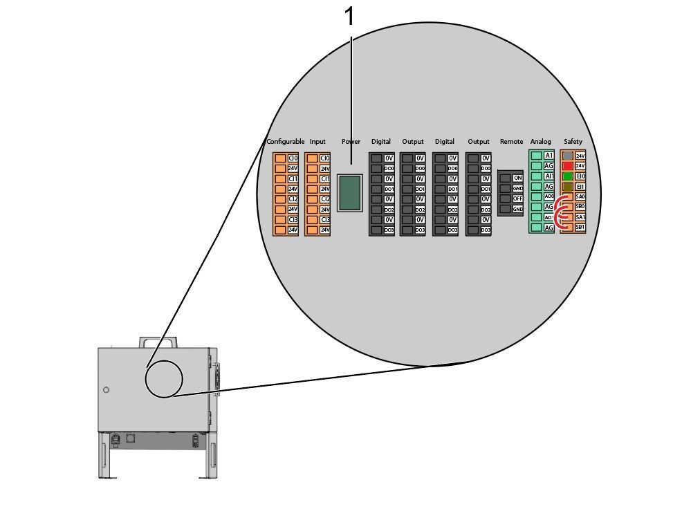
    6

    Download HRTool through HBC. On the Service section of HBC, navigate to Utilities > Documents and Software > 01 Control Software > 01 Next Generation Control > 10 Cobot Software > HRTool.zip.

    Unzip the folder and navigate to HRToolsMaind.exe.

    Insert the Cobot IP address found under the Systems tab.  Click Set. 

    Go to the Config tab on HRTool.

    Click "get" to see the actual vs. theoretical encoder values. 

    Click "set" to set the theoretical to the actual encoder values. This step sets the Cobot's current position as it's new home position. 

    7

    Make sure that each joint's actual and theoretical encoder values match. 

    NOTE: If the valuyes do not match, press "Set" again. 

    8

    On the teach pendant, navigate to System [1] and then Update System. 

    Confirm the Cobot firmware [2] is either:

    • HR5.51H.16.beta.20231213.zip
    • HR6.4.9.tmp.20240919.zip

    NOTE: Firmware version HR6.4.9.tmp.20240919.zip is compatible with all size cobots.

    Refer to the Haas Cobot - Maintenance chapter for the firmware update procedure. 

    9

    Turn on the Haas CNC.

    Zero Return all Axes.

    Insert Service USB key.  Go into Service mode.

    Go to Parameters> Factory tab.  Change the following:

    • 1278 [1278:] Robot Ready E-Stop Enabled to TRUE
    • 2191 [694:] LIGHT CUTAIN TYPE to LC_TYPE_1
    • 2194 [:] Enable Front Door Fully Open Switch to TRUE

    Note: Machines with Software Version 100.20.000.1010 or higher will need to change the following parameter:

    • 2192 [:] Light Curtain Trigger Threshold to 0

    Press [SETTING].

    Set the Settings:

    • 372 Parts Loader Type to 3: Robot.
    • 376 Light Curtain Enabled to On


    10

    On the Haas pendant, press [CURRENT COMMANDS].

    Go to Devices>Robot>Jogging tab. Change the following:

    • Maximum Jogging Speed to 7.9 inch/sec

     Note: The jogging increments on the RJH are a percentage of this max speed value. In order to decrease the distance the robot travels of each jog wheel tick, you need to change your Maximum Jogging Speed to a lower value.

    Go to the Setup tab. Change the following:

    • Max Robot Speed to 118 in/sec (2000 mm/sec). 
    • Enter the Net Mass of the gripper. Refer to the layout drawings on our website (Single Gripper layout drawing OR Dual Gripper layout drawing) to get the correct value for this setting
    WARNING: Setting this value incorrectly can cause the Robot Arm to not move correctly. 
     
    • Number of Grippers to the number of grippers.
    • Raw Gripper Clamp Output to 1.
    • Raw Gripper Unclamp Output to 2.
    • Raw Gripper Clamp Delay to the clamp/unclamp duration in sec.
    • Raw Gripper Clamp Type to OD/ID.
    • Finish Gripper Clamp Output to 3.
    • Finish Gripper Unclamp Output to 4.
    • Finish Gripper Clamp Delay to the clamp/unclamp duration in sec.
    • Raw Gripper Clamp Type to OD/ID.

    Security Risk Level

    1

    IMPORTANT: Make sure to perform an appropriate risk-assessment and met all appropriate safety requirements. 

    2

    Based off the risk assessment, set the appropriate security risk level on the Cobot teach pendant. Navigate to Config > General Restrictions and tap of the desired security risk level [1] from 0 - 5.

    Use the  "admin" code in the safety verification to change the security level.

    NOTE: When the security risk level is lower, the robot will have a lower maximum speed, force, etc. When the security risk level is higher, the robot will have a higher maximum speed, force, etc. 

    This security risk level will calculate the maximum allowable force, speed, power, momentum, elbow speed and elbow force [2] that the Cobot will withstand before Alarm 9150.10017 Collison Stop Error is triggered. 

    IMPORTANT: The robot's programmed speed cannot be greater than the allowable speed from the security risk level. 

    NOTE: For more information regarding alarms, refer to the Haas Cobot - Troubleshooting Guide. 

    Activation

    1

    Download and load the configuration files by logging into the HAAS SERVICE PORTAL.

    Download the safety automation option front/side configuration files.

    Load the option configuration patch file to the control. Refer to the NEXT GENERATION CONTROL - CONFIGURATION FILE - DOWNLOAD/LOAD procedure.

    2

    Go to Parameters > Features > Robot to verify that the robot feature has appeared on the bottom.

    3

    Press [CURRENT COMMANDS].

    Go to Devices>Robot>Setup tab [1].

    Press [E-Stop].

    Press [F1] to connect the robot[2].

    The first time connecting a robot to a machine, the robot feature will need to be unlocked. This popup shows the machine's current software version, robot mac address and a generated code. Enter this information into HBC in order to receive the unlock code.

    4

    On HBC, go to the Service tab [1].

    On the left hand side of the screen, click on Activations [2], and then select Cobot Installation [3] to begin the process to the get the Cobot unlock code.

    The first step is to enter the Machine Serial Number [4] and the Cobot Serial Number [5] in the fields on HBC.

    Once you have entered the correct information, press Next [6] in the bottom right corner and continue through the steps until you receive the unlock code.

    Note: Make sure you are on the Cobot Installation tab [3] and not the Robot Installation tab. The Robot Installation is only used for the Haas Robot Packages. Using the Robot Installation for the Haas Cobots will result in an invalid unlock code.

    5

    Enter the Cobot's Haas Serial Number[1] and the unlock code to connect the robot to the machine. 

     Note: This step can only be completed by a HFO Service Technician.

     Note: The machine needs to be activated before the Cobot is activated. Follow the Machine Activation / Time Extension - NGC procedure.

    When the robot has connected with the machine, a yellow message saying Robot Activation Successful should appear at the bottom of the Haas screen.

    6

    Release the [E-STOP] and press RESET to clear the alarms. 

    Press the [HANDLE JOG] button. 

    Press the [CURRENT COMMANDS]  and go to Devices > Robot > Jogging tab.

     Note: The robot in setup mode can only be handle jogged while the F2 button the RJH is pressed. See Setup/Run mode section below.

    On the Remote Handle Jog Touch press the Joint button to go into the Joints Coordinates.

    Move the robot to an accessible location to install the grippers.

    Jog J6 to 0.0000 position. The location hole should be centered on top.

    Note: Press [E-STOP] before working on the robot.

    Gripper Installation

    1

    Turn off the machine air by turning the valve in the Air/Lube cabinet and pull the pressure relief valve to release the air in the system.

    2

    For the Dual Action Gripper:

    There are two versions of the dual-action grippers for this section, both of which have the same installation process.

    Jog the robot so that the location hole [1] is centered on top.

    Install the adapter plate [2] onto the end of the robot arm.

    Install the dual gripper assembly [3] onto the adapter plate [2].

    NOTE: Make sure to install Gripper 1 (which has the orange and purple zip ties) onto the Gripper 1 adapter plate section. 

    3

    For the Angled Single Action Gripper:

    Jog the robot so that the location hole [1] should be centered on top.

    Install the angle adapter plate [2] to the end of the robot arm.

    Install the single gripper assembly [3] onto the angle adapter plate [2]. 

    4

    To install the bar gripper fingers, remove the slug gripper plates from the gripper bodies.

    Install the Bar Gripper Bolt Plates [3] with (x8) SHCS M6 screws [4]. Torque to 10 ft-lbs.

    Install the Bar Gripper Fingers [2] with (x8) SHCS 1/4-20 [1]. Torque to 13 ft-lbs.

    5

    Configure the dual air solenoid assembly used for pneumatic grippers depending on single [1] or dual [2] gripper configuration. 

    For single grippers [1], connect the incoming air to the to the fitting [2] and keep the plug in the other end of the fitting [3] as shown in the image.

    For dual grippers [4], remove the plug in the fitting [3] and attach a small air hose to the second solenoid [5]. Then connect the incoming air hose to the fitting [2] so that both solenoids are receiving air.

    6

    For the Single Gripper:

    Route the (x2) air lines from the gripper to the same color coded fitting on the dual air solenoid assembly. 

    Secure the air lines by wrapping them in cable conduit. Use the velcro straps to attach the cable conduit to the Cobot. Make sure there is enough slack so that cables aren't strained when Cobot is fully extended.

    Insert the input air hose to the used solenoid's fitting [1]. 

    Make sure the plug is installed onto the unused solenoid's fitting [2]. 

    7

    For the Dual Gripper:

    Route the (x2) air lines from gripper #1 to the same color coded fitting on the dual air solenoid assembly. 

    Route the (x2) air lines from gripper #2 to the same color coded fitting on the dual air solenoid assembly. 

    Secure the air lines by wrapping them in cable conduit. Use the velcro straps to attach the cable conduit to the Cobot. Make sure there is enough slack so that cables aren't strained when Cobot is fully extended.

    Insert the short airline [1] connecting the first solenoid with the second. 

    Insert the input air hose to the fitting [2]. 

    Parts Table Assembly

    If the parts table option was ordered, follow the procedure below for assembly instructions:

    Haas Robot - Parts Table Assembly

    NOTE: If HC10 MACHINE READY KIT was purchased, there is no need to install the wheels if mounting the parts table directly into the wooden pallet. 

    Verification

    Test the E-stop:

    • Press each E-STOP button located on the Haas Pendant, RJH-XL, and Cobot Teach Pendant. Make sure the machine generates 107 EMERGENCY STOP alarm.  If the E-STOP button does not generate a 107 EMERGENCY STOP alarm verify the wiring. Load the latest configuration files to enable the RJH-XL.

    Test the Robot Safety Device:

    Make sure that there is an E-STOP or light curtain triggered icon on the Haas pendant when the robot safety device is triggered. 

    • Fence - Insert the key into the interlock, verify that the two red LED lights in the front of the interlock are OFF. Remove the key from the interlock, verify that the two red LED lights are ON. 
    • Area Scanner - Step inside the protective field, verify that the red LED lights up on the area scanner. Step outside the protective field, verify that the green LED lights up.
    • Light Curtain - Interfere the light curtain beams, verify that the light curtain triggered icon appears on the Haas pendant. Press [RESET]. Step outside of the light curtain beams, verify no icon appears on the Haas pendant. 

    NOTE: If the light curtain triggered icon does not show, verify wiring, alignment and factory setting: 2191 [694:] LIGHT CURTAIN TYPE is set to LC_TYPE_1.

    Test the Operation of the Grippers:

    • Verify that both grippers clamp and unclamp correctly.
    • Press the [CURRENT COMMANDS]  and go to Devices > Robot > Jogging tab.
    • Press [F2] to clamp/unclamp the Finish Gripper.
    • Press [F3] to clamp/unclamp the Raw Gripper.

    Test the Remote Jog Handle:

    • Undock the Remote Jog Handle
    • Press the [HANDLE JOG] button. 
    • Press the [CURRENT COMMANDS]  and go to Devices > Robot > Jogging tab.
    • On the Remote Handle Jog press the Joint button to go into the Joints Coordinates.
    • Move the robot to a safe location.

    IMPORTANT: If a yellow warning message appears saying "Please activate Light Curtain or Cell Safe" while trying to job the robot, verify the safety parameter was applied by re-uploading the configuration files from HBC. 

    Verify Safe / Run Mode Operation

    All Haas CNC machines are equipped with a key switch on the side of the control pendant to lock and unlock setup mode. The robot will have the following behaviors depending on what mode is selected. 

    • When the Haas control is in Run mode, mode 1, triggering the robot safety device stops all motion. This motion can not be started until the robot safety device is no longer triggered.
    • When the Haas control is in Set up mode, mode 2, speed limited motion such as jogging an axis of the robot can be performed in order to program a robot's path of motion, pick up position, set a robot's tool center point, (an offset), load and pick up parts from the spindle or part holder in the machine, etc. The programmed path will also be able to be run slowly to prove out the programmed path of the robot. The robot in setup mode can only be handle jogged while the F2 button the RJH is pressed.

    Haas Robot - Quick Start Guide

    När roboten har installerats ställs ett jobb in enligt följande procedur.

    Haas Robot – Snabbstartsguide

    Disable the Robot

    Avaktivera roboten för att köra maskinen i fristående läge. Tryck på [SETTING] (inställning). Ändra följande inställningar:

    • 372 – Typ av detaljladdare på0: Ingen
    • 376 – Aktiverad ljusridå på AV
    Feedback

    Recently Viewed Items

    You Have No Recently Viewed Items Yet

    Feedback
    Haas Logo

    Haas pris inkl. frakt

    I detta pris ingår frakt, export- och tullavgifter, försäkring och övriga kostnader som uppstår för leverans till överenskommen plats. Inga övriga obligatoriska kostnader kan läggas till för leverans av Haas CNC-produkt.

    HÅLL DIG UPPDATERAD OM TIPS OCH TEKNIK FRÅN HAAS ...

    Anmäl dig nu!   

    HAAS TOOLING ACCEPTERAR FÖLJANDE:

    • Service och support
    • Ägare
    • Beställ service
    • Bruksanvisningar
    • Haas reservdelar
    • Reparationsförfrågan, rundmatningsbord
    • Förinstallationsguider
    • Köpa verktyg
    • Bygg och prissätt en ny Haas
    • Tillgänglig inventorie
    • Haas prislista
    • CNCA-finansiering
    • Om Haas
    • Tillgänglighetsmeddelande
    • DNSH-meddelande
    • Exportöverensstämmelse
    • Karriär
    • Certifieringar och säkerhet
    • Kontakta oss
    • Historik
    • Villkor och bestämmelser
    • Villkor och bestämmelser för Haas verktyg
    • Integritet
    • Garanti
    • Haas Community
    • Haas certifieringsprogram
    • Haas Motorsport
    • Gene Haas Foundation
    • Haas gemenskap för teknisk utbildning
    • Evenemang
    • Delta i samtalet
    • Facebook
    • X
    • Flickr
    • YouTube
    • LinkedIn
    • Instagram
    • TikTok
    © 2026 Haas Automation, Inc – CNC-verktygsmaskiner

    This site is protected by reCAPTCHA and the Google Privacy Policy and Terms of Service apply.

    2800 Sturgis Rd., Oxnard, CA 93030 / Toll Free: 800-331-6746
    Phone: 805-278-1800 / Fax: 805-278-2255