My Haas Dobro došli,
!
Haas Tooling MyHaas/HaasConnect Prijava Registrirajte se Haas Tooling MyHaas/HaasConnect Odjava Dobro došli, Moji strojevi Zadnja aktivnost Moje ponude Moj račun Moji korisnici Odjava
Pronađite zastupnika
  1. Odaberite jezik
    1. English
    2. Deutsch
    3. Español - ES
    4. Español - MX
    5. Français
    6. Italiano
    7. Português
    8. Český
    9. Dansk
    10. Nederlands
    11. Magyar
    12. Polski
    13. Svenska
    14. Türkçe
    15. 中文
    16. Suomi
    17. Norsk
    18. الإنجليزية
    19. български
    20. Hrvatski
    21. Ελληνικά
    22. Română
    23. Slovenský
    24. Slovenščina
    25. 한국어
    26. 日本語
    27. Українська
  • strojevi Main Menu
    • Vertikalne glodalice
      Vertikalne glodalice
      Vertikalne glodalice View All
      • Vertikalne glodalice
      • Serija VF
      • Univerzalni strojevi
      • VR serija
      • VP-5 prizmatski stroj
      • VMC-ovi za izmjenu paleta
      • Male glodalice
      • Strojevi za modeliranje
      • Centri za bušenje velike brzine
      • Serija strojeva za bušenje/narezivanje/glodanje
      • Alatne glodalice
      • Pocket Mill
      • Kompaktne glodalice
      • Serije pokretnih postolja
      • SR Usmjernici za ploče
      • Iznimno veliki VMC strojevi
      • Glodalice s dvostrukim stupcem
    • Višeosna rješenja
      Višeosna rješenja
      Višeosna rješenja View All
      • Višeosna rješenja
      • Y-osne tokarilice
      • 5-osne glodalice
    • Tokarilica
      Tokarilica
      Tokarilica View All
      • Tokarilica
      • ST serije
      • Dva glavnog vretena
      • Serija Box Way
      • Alatne tokarilice
      • Konjić tokarilice
      • Tokarilica za džepove
      • Haas dodavači šipki
    • Horizontalne glodalice
      Horizontalne glodalice
      Horizontalne glodalice View All
      • Horizontalne glodalice
      • 50-konusni
      • Konus 40
    • rotacioni proizvodi i indekseri
      rotacioni proizvodi i indekseri
      rotacioni proizvodi i indekseri View All
      • rotacioni proizvodi i indekseri
      • Okretni stolovi
      • Indekseri
      • 5-osne rotacione jedinice
      • Iznimno velike rotacione jedinice
    • Sustavi automatizacije
      Sustavi automatizacije
      Sustavi automatizacije View All
      • Sustavi automatizacije
      • Automatizacija glodalice
      • Automatizacija tokarilice
      • Automatski sustavi za dodavanje sirovca
      • Modeli za automatizaciju
    • Desktop strojevi
      Desktop strojevi
      Desktop strojevi View All
      • Desktop strojevi
      • Desktop glodalica
      • Desktop tokarilica
      • Upravljački simulator, standardni
      • Upravljački simulator, Premium
    • Oprema za radionice
      Oprema za radionice
      Oprema za radionice View All
      • Oprema za radionice
      • Konzolna glodalica
      • Haas ručne tokarilice
      • Haas pile
    • Strojevi za izradu
      Strojevi za izradu
      Strojevi za izradu View All
      • Strojevi za izradu
      • Laserski strojevi za rezanje
      • CNC preše za savijanje
    • BRZE POVEZNICE Posebne serije  Posebne serije 
      EU SERIJE EU SERIJE KONFIGURACIJA I CIJENA | CJENIK KONFIGURACIJA I CIJENA | CJENIK Strojevi na zalihi Strojevi na zalihi ŠTO JE NOVO ŠTO JE NOVO VAŠ PRVI CNC VAŠ PRVI CNC
      ALATI ZA KUPNJU
      • Sastavite i izradite cijenu Haas stroja
      • Cjenik
      • Dostupan inventar
      • CNCA financiranje
      ŽELITE RAZGOVARATI S NEKIM?

      Haas tvornički dućan (outlet) (HFO) može odgovoriti na vaša pitanja i provesti vas kroz najbolje opcije.

      CONTACT YOUR DISTRIBUTOR >
  • Opcije Main Menu
    • The Haas Control Paketi vrijednosnih opcija
      Paketi vrijednosnih opcija
      Paketi vrijednosnih opcija View All
      • Paketi vrijednosnih opcija
    • Product Image Glavna vretena
      Glavna vretena
      Glavna vretena View All
      • Glavna vretena
    • Product Image Izmjenjivači alata
      Izmjenjivači alata
      Izmjenjivači alata View All
      • Izmjenjivači alata
    • Product Image 4- | 5-osni
      4- | 5-osni
      4- | 5-osni View All
      • 4- | 5-osni
    • Product Image Revolveri i pogonjeni alati
      Revolveri i pogonjeni alati
      Revolveri i pogonjeni alati View All
      • Revolveri i pogonjeni alati
    • Product Image Sondiranje
      Sondiranje
      Sondiranje View All
      • Sondiranje
    • Haas Upravljanje strugotinom i rashladnim sredstvima Upravljanje strugotinom i rashladnim sredstvima
      Upravljanje strugotinom i rashladnim sredstvima
      Upravljanje strugotinom i rashladnim sredstvima View All
      • Upravljanje strugotinom i rashladnim sredstvima
    • Haas upravljačka naprava Haas upravljačka naprava
      Haas upravljačka naprava
      Haas upravljačka naprava View All
      • Haas upravljačka naprava
    • Product Image Opcije proizvoda
      Opcije proizvoda
      Opcije proizvoda View All
      • Opcije proizvoda
    • Product Image Alati i Stezanje i prihvat sirovca
      Alati i Stezanje i prihvat sirovca
      Alati i Stezanje i prihvat sirovca View All
      • Alati i Stezanje i prihvat sirovca
    • Product Image Držač obratka
      Držač obratka
      Držač obratka View All
      • Držač obratka
    • Product Image 5-osna rješenja
      5-osna rješenja
      5-osna rješenja View All
      • 5-osna rješenja
      • 5 Easy Steps to 5-Axis
    • Product Image Automatizacija
      Automatizacija
      Automatizacija View All
      • Automatizacija
    • BRZE POVEZNICE Posebne serije  Posebne serije 
      EU SERIJE EU SERIJE KONFIGURACIJA I CIJENA | CJENIK KONFIGURACIJA I CIJENA | CJENIK Strojevi na zalihi Strojevi na zalihi ŠTO JE NOVO ŠTO JE NOVO VAŠ PRVI CNC VAŠ PRVI CNC
      ALATI ZA KUPNJU
      • Sastavite i izradite cijenu Haas stroja
      • Cjenik
      • Dostupan inventar
      • CNCA financiranje
      ŽELITE RAZGOVARATI S NEKIM?

      Haas tvornički dućan (outlet) (HFO) može odgovoriti na vaša pitanja i provesti vas kroz najbolje opcije.

      CONTACT YOUR DISTRIBUTOR >
  • Why Haas Main Menu
      Otkrijte Haas razliku
    • Zašto Haas
    • MyHaas
    • Edukacijska zajednica
    • Industry 4.0
    • Haas certifikat
    • Svjedočenja kupaca
  • Servis Main Menu
      Dobrodošli u Haas Service
      POČETNA STRANICA SERVISA Priručnici za korisnika Upute za izvršenje Upute za rješavanje problema Preventivno održavanje Haas dijelovi Haas Tooling Videozapisi
  • Videozapisi Main Menu
My Haas Dobro došli,
!
Haas Tooling MyHaas/HaasConnect Prijava Registrirajte se Haas Tooling MyHaas/HaasConnect Odjava Dobro došli, Moji strojevi Zadnja aktivnost Moje ponude Moj račun Moji korisnici Odjava
Pronađite zastupnika
  1. Odaberite jezik
    1. English
    2. Deutsch
    3. Español - ES
    4. Español - MX
    5. Français
    6. Italiano
    7. Português
    8. Český
    9. Dansk
    10. Nederlands
    11. Magyar
    12. Polski
    13. Svenska
    14. Türkçe
    15. 中文
    16. Suomi
    17. Norsk
    18. الإنجليزية
    19. български
    20. Hrvatski
    21. Ελληνικά
    22. Română
    23. Slovenský
    24. Slovenščina
    25. 한국어
    26. 日本語
    27. Українська
×

Rezultati pretrage

Web Pages

Images

    • <
    • 1
    • >

5 - HC10 - Installation

Haas Cobot Package - Operator's/Service Manual


  • 0 - Haas Kobot - Tablica sadržaja
  • 1 - Haas Cobot - Introduction
  • 2 - Haas Cobot - Legal Information
  • 3 - Haas Cobot - Safety
  • 4 - HC5 - Installation
  • 5 - HC10 - Installation
  • 6 - HC15 - Installation
  • 7 - HC30 - Installation
  • 8 - Haas Cobot - Fence/Interlock Installation
  • 9 - Haas Cobot - Area Scanner Installation
  • 10 - Haas Cobot - Light Curtain Installation
  • 11 - Haas Cobot - Operation
  • 12 - Haas Cobot - Maintenance
  • 13 - Haas Cobot - Troubleshooting

Go To :

  • 5.1 Instalacija VMC-a
  • 5.2 Instalacija tokarilice
  • 5.3 DM/DT/MM/DC-1/UMC-350 Instalacija
  • 5.4 UMC-400/500 Instalacija

5.1 Instalacija VMC-a

Recently Updated

Haas Kobot 10 (HC10) - VMC - Instalacija


AD0714

Revizija C - 09/2025

Introduction

Ovaj postupak pokazat će vam kako ugraditi Haas 10KG kobot (HC10).

 Napomena: Radna ćelija koju je dizajnirao Haas i koja se sastoji od CNC stroja i robota procijenjeni su za usklađenost s CE zahtjevima. Promjene ili varijacije dizajna ćelija tvrtke Haas trebaju se procijeniti u pogledu usklađenosti s primjenjivim standardima i odgovornost su korisnika/integratora.

Updated

Zahtjevi za stroj:

  • 100.24.000.1001 verzija ili novija
  • Verzija
  • HR5.51H.16.beta.20231213.zip ili verzija HR6.4.9.tmp20240919.zip
  • VF-1/2 i VM-2 Proizvedeno nakon datuma:  (pogledajte zahtjeve stroja u oba postupka) 
  • DC-2
  • Haas automatska vrata 
  • Haas Automatski prozor
  • 34-349xB I/O ploča ili novija
  • 93-1000610 DALJINSKA RUČICA ZA RUČNO POMICANJE OSI STROJA S DODIRNIM LCD EKRANOM (RJH-XL) DALJINSKA RUČICA ZA RUČNO POMICANJE OSI STROJA - XL
  • Potreban alat:

    • Mali ravni odvijač

    Zahtjevi za učvršćivanje/ankeriranje

    • Haas  10KG Kobot (HC10) konfiguriran je i prodaje se od strane Haas s postoljem/stolom koji je dovoljno stabilan kada se koristi u skladu s Haas definiranim ograničenjima veličine i težine dijelova. 
    VAŽNO:  Za više informacija izravno o Hans Kobotu, pogledajte Hans Robot priručnik za rad s Elfin softverom.

    Postoje 3 scenarija u kojima se opcija kobota može ugraditi na Haas stroj:

    1. Opcija kobota naručena je istovremeno kao i stroj. I kobot i stroj se ugrađuju zajedno.
    2. Opcija kobota naručuje se za ugradnju na prethodno ugrađeni stroj.
    3. Opcija kobota prethodno je bila ugrađena na stroj, ali će sada biti premještena na drugi Haas stroj.

    U scenarijima 2 i 3, dodatni dijelovi trebat će se naručiti pod serijskim brojem Haas stroja. Pogledajte tablice u nastavku za dijelove koji su potrebni u različitim scenarijima.

    Scenarij 1 - Kobot i stroj naručeni su i instaliraju se zajedno

    Dio Broj dijela Opis
    NIJE POTREBNO NARUČITI DODATNE DIJELOVE KADA SE KOBOT I STROJ NARUČUJU ZAJEDNO

    Scenarij 2 - Kobot se ugrađuje na terenu na postojeći Haas stroj

    Dio Broj dijela Opis
    PROVJERITE IMA LI HAAS STROJ VEĆ OVE ZNAČAJKE&PARAMETRE PRIJE NARUČIVANJA
    Parametar otključavanja značajke robota 93-1001031 Komplet aktivira značajku robota na Haas stroju. Da biste provjerili trebate li ovaj komplet, idite na karticu Značajke  na Haas upravljačkoj jedinici i provjerite je li istaknuta opcija Robot. Ovaj komplet ne uključuje fizičke dijelove.
    Sigurnosni parametri vrste opterećenja 93-1000997 Sigurnosni parametri prednje automatizacije - Komplet je potreban kada će kobot puniti dijelove kroz prednja vrata Haas stroja. Ovaj komplet ne uključuje fizičke dijelove, a opcija automatskih vrata trebala bi se kupiti i ugraditi zasebno.
    ILI  
    93-1000996 Sigurnosni parametri bočne automatizacije - Komplet je potreban kada će kobot puniti dijelove kroz bočni prozor Haas stroja. Ovaj komplet ne uključuje fizičke dijelove, a opcija automatskog prozora trebala bi se kupiti i ugraditi zasebno.

    Scenarij 3 - Kobot se premješta s jednog stroja na drugi Haas stroj

    Dio Broj dijela Opis
    Komplet za integraciju kobota Pogledajte Tablicu kompatibilnosti kompleta za integraciju Komplet je potreban za ugradnju dijelova na Haas stroj za sučelje s kobotom. To uključuje kutiju sučelja, prekidače na vratima itd., kao i parametar Značajka otključavanja robota. Ovaj komplet treba kupiti samo kada se kobot prenosi na novi Haas stroj jer su ovi dijelovi obično uključeni kada se naručuje kobot. 
    Sigurnosni parametri vrste opterećenja 93-1000997 Sigurnosni parametri prednje automatizacije - Komplet je potreban kada će kobot puniti dijelove kroz prednja vrata Haas stroja. Ovaj komplet ne uključuje fizičke dijelove, a opcija automatskih vrata trebala bi se kupiti i ugraditi zasebno.
    ILI  
    93-1000996 Sigurnosni parametri bočne automatizacije - Komplet je potreban kada će kobot puniti dijelove kroz bočni prozor Haas stroja. Ovaj komplet ne uključuje fizičke dijelove, a opcija automatskog prozora trebala bi se kupiti i ugraditi zasebno.
    Sigurnosni uređaj 08-1899 Komplet svjetlosne zavjese s više strana - Komplet je potreban ako se sigurnosni uređaj NE prenosi s prvog stroja, a drugi Haas stroj treba vlastiti sigurnosni uređaj. Ovaj komplet stvara 4-stranu zaštitnu barijeru.
    ILI  
    08-1948 Komplet svjetlosne zavjese s 5 strana - Komplet je potreban kada se sigurnosni uređaj NE prenosi s prvog stroja, a drugi Haas stroj treba vlastiti sigurnosni uređaj. Ovaj komplet stvara 5-stranu zaštitnu barijeru.
    ILI  
    08-1987 Komplet laserskog skenera područja - Komplet je potreban kada se sigurnosni uređaj NE prenosi s prvog stroja , a drugi Haas stroj treba vlastiti sigurnosni uređaj. Ovaj skener područja ima udaljenost otkrivanja od 4 metra.

    Mill Setup

    1

    Obavite sljedeće postupke s obje strane vrata:

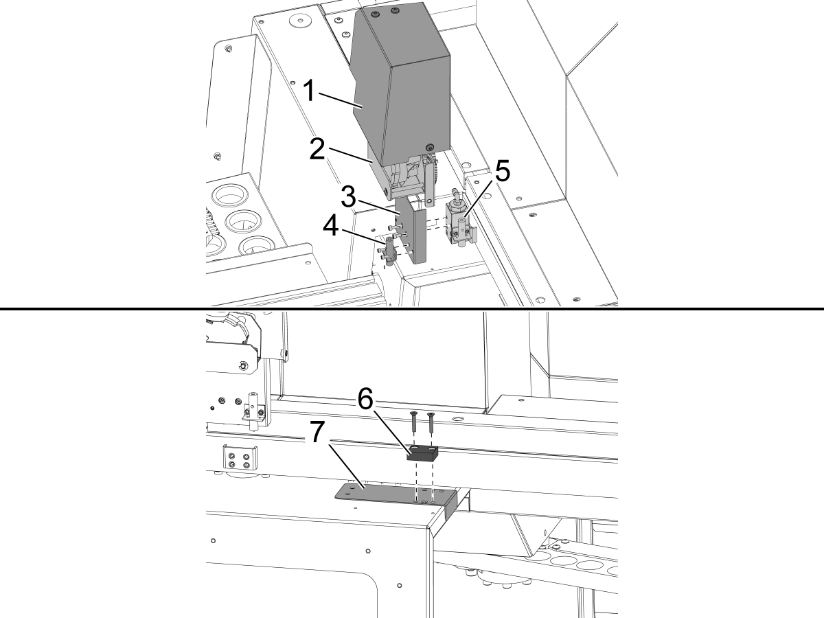
    Uklonite poklopac motora automatskih vrata [1] i sklop motora automatskih vrata [2].

    Ugradite novi nosač blizinskog prekidača [3] na postojeći blok blizinskog prekidača [5].

    Ugradite blizinski prekidač uvijek otvorenih vrata [4] na nosač [3].

     Važno: Postoje 2 predloška bušenja uključena u VMC komplet. Postoji VF predložak [8] i jedinstveni predložak [9] specifičan za DC-2 strojeve. DC-2 predložak treba koristiti umjesto standardnog VF predloška na DC-2 strojevima.

    Ugradite vodilicu za bušenje [7] za oznaku za otvorena vrata [6] te izbušite i urežite navoje na 2 rupe 10-32 kroz metalni lim vrata.

    • Veličina bušenja: # 21 ili 5/32"
    • Urežite navoje 10-32 NF

    Uklonite predložak i ugradite oznaku za otvorena vrata pomoću 2 vijka s plosnatom glavom. Ponovno ugradite sklop motora automatskih vrata, nosač i poklopac.

    Upotrijebite priložene podloške za postavljanje visine između blizinskog prekidača i oznake za otvorena vrata.

    2

    Robot za umetanje sprijeda: 

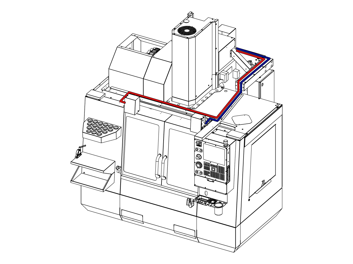
    Provedite kabel u upravljački ormarić kako je prikazano na slici.

    Isključuje stroj.

    Spojite na 32-0807 PROX NIJEDNA LIJEVA VRATA POTPUNO OTVORENA na SIO PCB P27.

    Spojite na 32-0856 PROX NIJEDNA DESNA VRATA POTPUNO OTVORENA na SIO PCB P72.

    Uključite stroj. 

    3

    Robot za bočno punjenje:

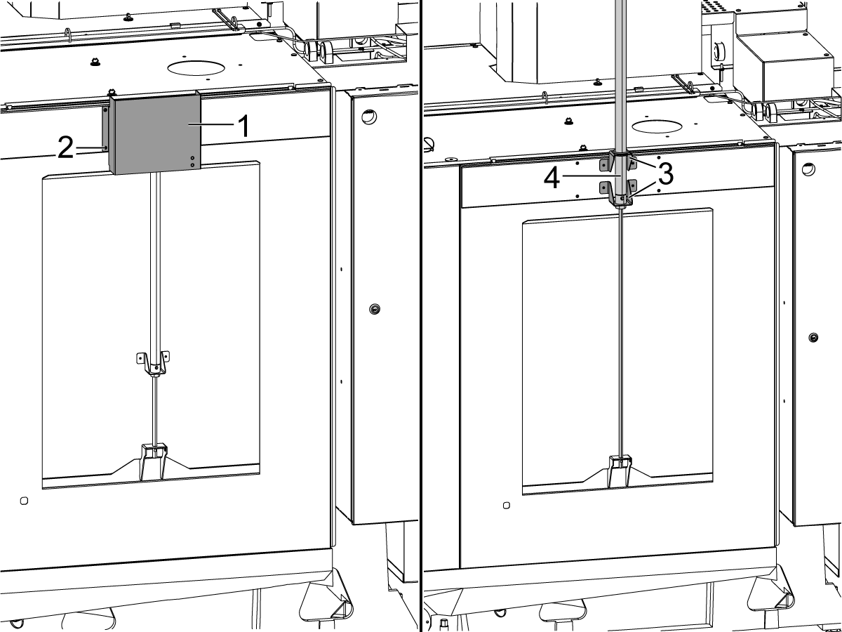
    Uklonite poklopac [1] i njegov okov [2] kako biste izložili zračni cilindar [4] automatskog prozora. Podignite zračni cilindar [4] tako da nosači [3] i zračni cilindar budu pričvršćeni kako je prikazano.

    Spojite priložena siva i žuta crijeva za zrak na zračni cilindar automatskog prozora - priključci na zračnom cilindru imat će sive i žute vezice koje pokazuju gdje se svako crijevo spaja.

    Ugradite poklopac [2] preko zračnog cilindra automatskog prozora.

    4

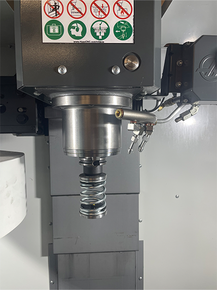
    • Opružni potiskivač izrađen je s drškom koja odgovara držaču alata od 25 mm ili 1"
    • Ovaj alat mora preuzeti držač alata u karuselu alata.
    • Programirajte sljedeće korake na početak bilo kojeg  programa kako biste se uvjerili da je dio pravilno smješten u steznu glavu:
      • Pronađite opružni potiskivač iznad dijela
      • Pomičite Z-os da sabijete oprugu oko 0,50 inča ili 12,7 mm
      • Otvorite škripac sa stankom od jedne sekunde
      • Zatvorite škripac sa stankom od jedne sekunde

    Napomena: Broj dijela za potiskivač opruge je: 

    • 30-12642 POTISKIVAČ OPRUGE APL.  Držač od 25 mm ili 1,0"" prodaje se zasebno.

    Cobot Installation

    1

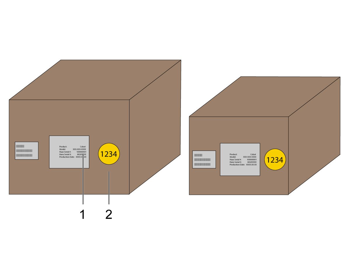
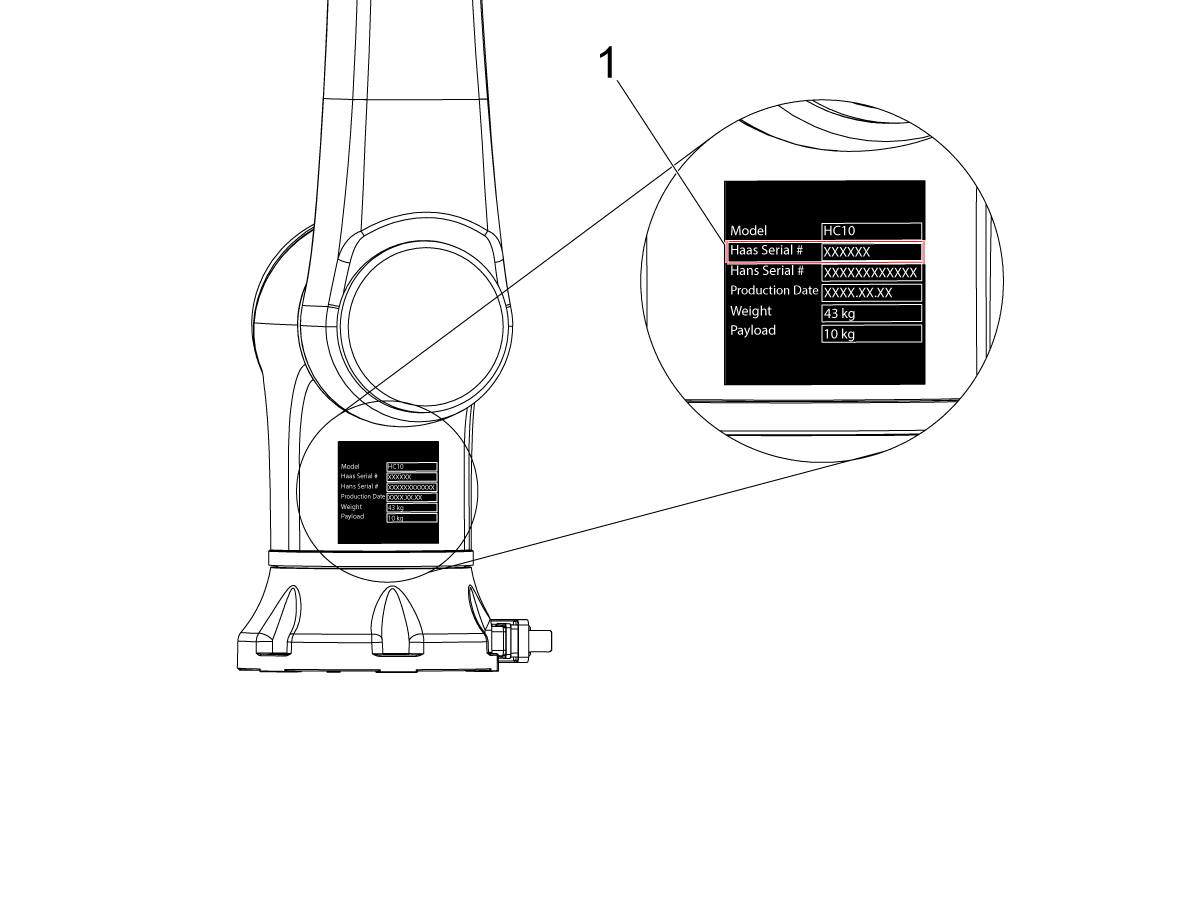
    Provjerite jesu li kobot i njegova upravljačka kutija iz istog odgovarajućeg kompleta s odgovarajućim serijskim brojevima.

    Postoji bijela naljepnica s Haas serijskim brojem [1]. Pobrinite se da su isti na obje kutije.

    Postoji žuta okrugla naljepnica s identifikacijskim brojem [2]. Pobrinite se da su isti na obje kutije.

    2

    Izmjerite ove dimenzije od ruba stroja do bočne strane postolja.

     Preporučene  udaljenosti su sljedeće dimenzije. Položaj može varirati ovisno o primjeni korisnika.

    Koristite dimenzije u sljedećim koracima kao referencu za kobote s prednjim i bočnim punjenjem. 

    Haas Kobot 10 preporučuje se koristiti u paru s Haas Cobot  postoljem. Ovo postolje je konfigurirano tako da bude dovoljno stabilno kada se koristi sukladno Haas definiranoj veličini obratka i ograničenjima težine. 

    3

    Prednje punjenje:

    Postavite postolje i stol za dijelove na sljedeću lokaciju u odnosu na stroj:

    Dimenzija Imperijalne (inči) Metrički (cm)
    Od prednje strane stroja do prednje strane postolja [1] 5,5 in. 14 cm.
    Od lijeve strane stroja do lijeve strane postolja[2] 29,5 in. 75 cm.
    Od prednje strane stroja do prednje strane stola za dijelove[4] 22 in. 56 cm.
    Od lijeve strane stroja do lijeve strane stola za dijelove [4] 10 in. 25,4 cm.

    4

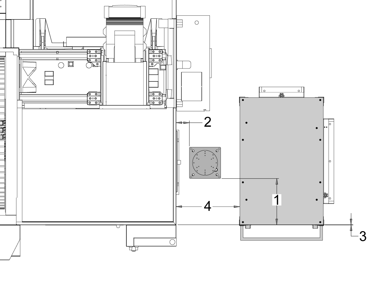
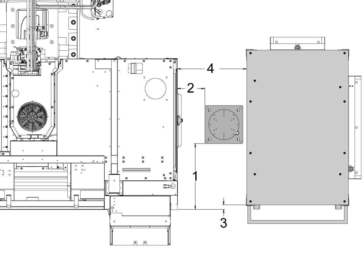
    Bočno umetanje:

    Postavite postolje i stol za dijelove na sljedeću lokaciju u odnosu na stroj:

    Dimenzija Imperijalne (inči) Metrički (cm)
    Od prednje strane stroja do lijeve strane postolja [1] 20,5 in. 52 cm.
    Od desne strane stroja do prednje strane postolja[2] 8,5 in. 21,6 cm.
    Od prednje strane stroja do lijeve strane stola za dijelove[3] 1,5 in. 3,8 cm.
    Od desne strane stroja do prednje strane stola za dijelove [4] 21,5 in. 54,6 cm.

    5

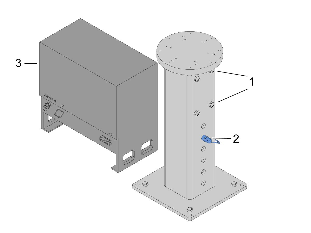
    Usidriti postolje u pod. Nivelirajte postolje pomoću libele.

    NAPOMENA: Za podesivo postolje, postavite željenu visinu otpuštanjem uvrtnih vijaka [1], a zatim podešavanjem rascjepke [2]. Ponovno zategnite uvrtne vijke [1] prije instalacije robota. Postavite libelu na vrh postolja dok koristite (x4) šesterokutne vijke na bazi za postavljanje ravnine u X & Y ravnini.

    Postavite upravljačku kutiju kobota [3] izravno pored postolja kako biste osigurali dovoljno slobodnog prostora za kabele. 

    6

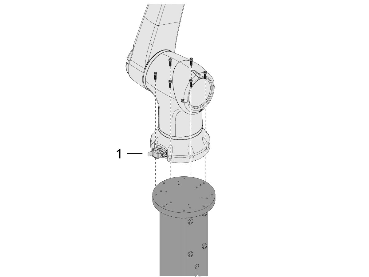
    Uklonite kobot iz transportne kutije.

    Napomena: Instalirajte adapter ploču između postolja i robota ako je potrebno.

    Ugradite kobot na vrh postolja s (x6) vijaka.

    NAPOMENA: Pobrinite se da je priključak kabela kobota [1] okomit na prednju stranu stroja. 

    VAŽNO: Kobot teži oko 40 lbs i trebao bi se podići uređajem koji može sigurno podići tu težinu.

    7

    Unutar pakiranja kobota nalazi se mala vrećica [1] ispunjena rezervnim dijelovima, uključujući: 

    • osigurač
    • Vijci (x2)
    • Ključevi upravljačke kutije

    Postoji srednja vrećica [2] ispunjena dodatnim M12 priključkom. Ovaj kabel može se koristiti za konfiguriranje ulaza i izlaza za Krajnji I/O modul. 

    Postoji velika vrećica [3] ispunjena papirima i USB stikom na koji je preuzet softver za kobot.

    Pobrinite se da ove rezervne dijelove čuvate na sigurnom mjestu za buduću upotrebu. 

    Robot Electrical & Air - Installation

     DANGER: Working with the electrical services required for CNC machines is extremely hazardous and can result in serious injury or death.

    Before connecting line wires to the CNC:

    • Turn off all power to the machine at the source.
    • Perform a Lockout-Tagout (LOTO) procedure to ensure the power remains off during service.
    • Verify that power has been disconnected by using an AC voltage detector on all incoming lines.

    If you are uncertain about how to safely disconnect power or perform LOTO procedures:

    • Do not proceed.
    • Contact qualified personnel or obtain appropriate assistance before continuing.

    Failure to follow these precautions may result in electrical shock, equipment damage, or fatal injury.

     Danger: Before beginning any work inside the control cabinet, verify that the High Voltage indicator light on the 320V Power Supply / Vector Drive has been off for a minimum of five (5) minutes. This waiting period ensures that residual voltage has dissipated and reduces the risk of electric shock.

    Certain service procedures involve high-risk electrical components and may pose serious injury or fatality hazards. Technicians must not attempt any procedure unless they have a complete understanding of the steps involved and the associated risks.

    If there is any uncertainty regarding a procedure, contact your Haas Factory Outlet (HFO) to arrange for a qualified service technician.

    1

    Spojite kutiju sučelja na Haas stroj:

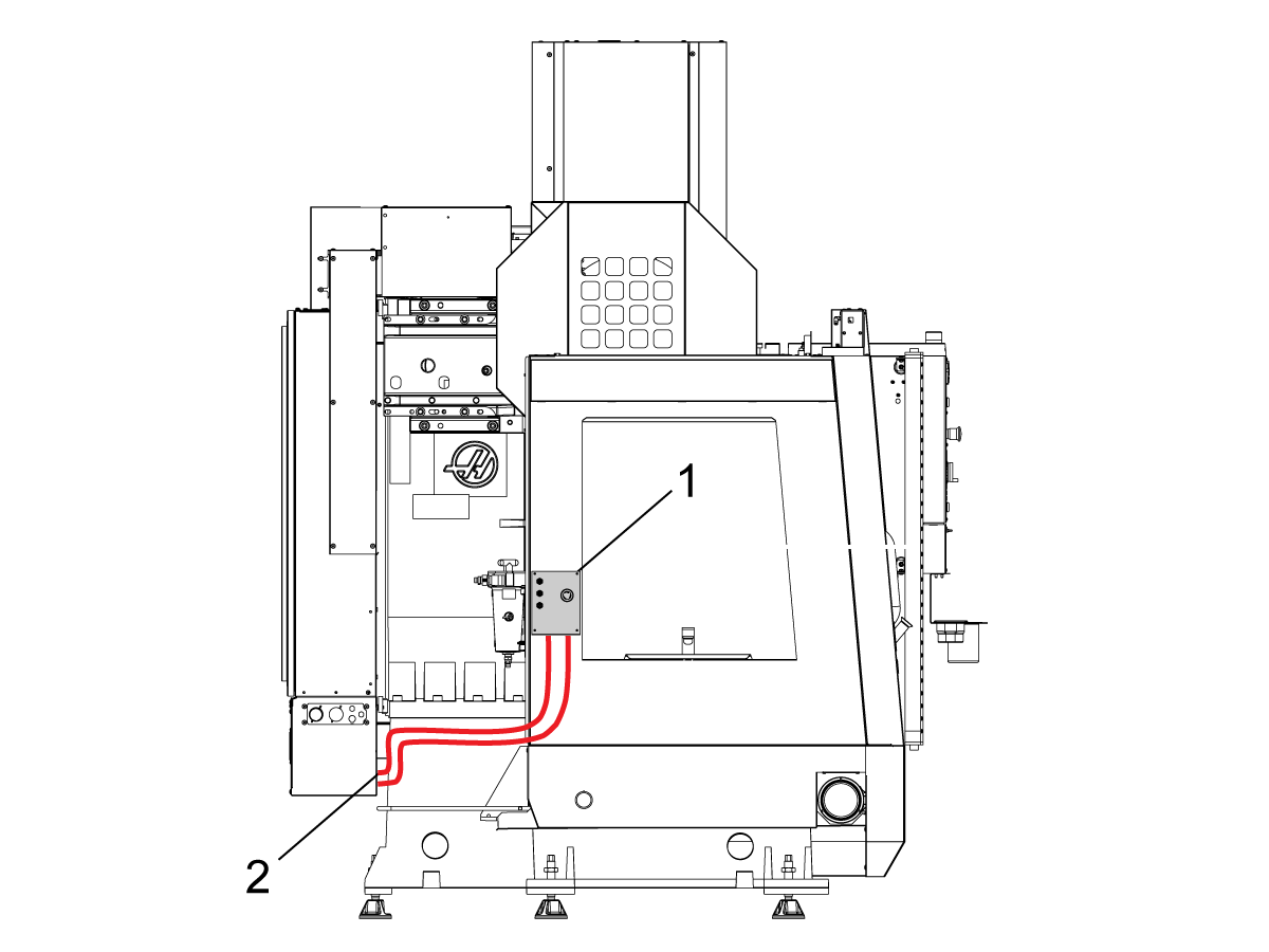
    Kutija sučelja za sigurnosne uređaje robota 32-9018 ima magnetske nosače za pričvršćivanje na lim stroja. Montirajte kutiju sučelja [1] kako je prikazano na slici.

    Provedite električne kabele sučelja [2] duž kućišta s magnetskim nosačima i vezicama za kabele. Provedite električne kabele sučelja robota kroz dno električnog ormarića.

    NAPOMENA: Za informacije o nadogradnji kutije sučelja na kutiju sučelja za sigurnosne uređaje robota, pogledajte Kutija sučelja za sigurnosne uređaje robota - Ugradnja - AD0703. 

    2

    Spojite kutiju sučelja na Haas upravljački ormarić:

    Spojite kabel 33-8562C priključnog bloka E-STOP na TB-1B  [1] i spojite priključni blok za način rada za određivanje postavki na TB-3B [1] na SIO PCB-u.  

    Uključite korisnički relej u K9 i K10 [2].

    Provjerite  je li premosnik ugrađen na SIO PCB na JP1.

    Spojite fleksibilni kabel s oznakom P1 SIO na SIO PCB na P1 [3]

    NAPOMENA: Ako stroj ima Regen vektorski pogon, odspojite kabel 33-0634 FILTER OV TO IOPCB P1 iz P1 SIO i spojite ga u konektor FILTER OV FAULT na kabelu 33-8562C. Ako stroj nema vektorski pogon Regen , ništa ne priključujte u konektorFILTAR OV POGREŠKA.

    Spojite  RJ-45  kabel [4] na Ethernet na USB adapter [5] (33-0636).  Spojite USB priključak na Maincon PCB J8 gornji ulaz.  Dodajte feritni filtar [6] na USB adapter.

    Montirajte napajanje 24VDC [7] na lijevu stranu upravljačkog ormarića i priključite u konektor označen 24V PS na kabelu 33-8562C. Spojite kabel 33-1281 [8] na 24VDC napajanje [7] i priključite u P3 na PSUP PCB. 

    3

    Za MM/SMM CM/CL strojeve bez XMR

    Ako je P3 zauzet premosnicima spojenim od P3 [10] do P7 [9] na PSUP PCB-u, potreban je razdjelnik kabela kako bi se omogućilo da napajanje 24VDC [7] bude spojeno na 120VAC priključke na PSUP-u. Spojite muški priključak razdjelnika kabela na P3 [10], a zatim spojite premosnike od tog kabela na P7 [9] i također kabel 33-1281 [8].

    Napomena: Pobrinite se da je premosni kabel spojen tamo gdje se crvena linija poklapa s crvenom linijom razdjelnog kabela.

    4

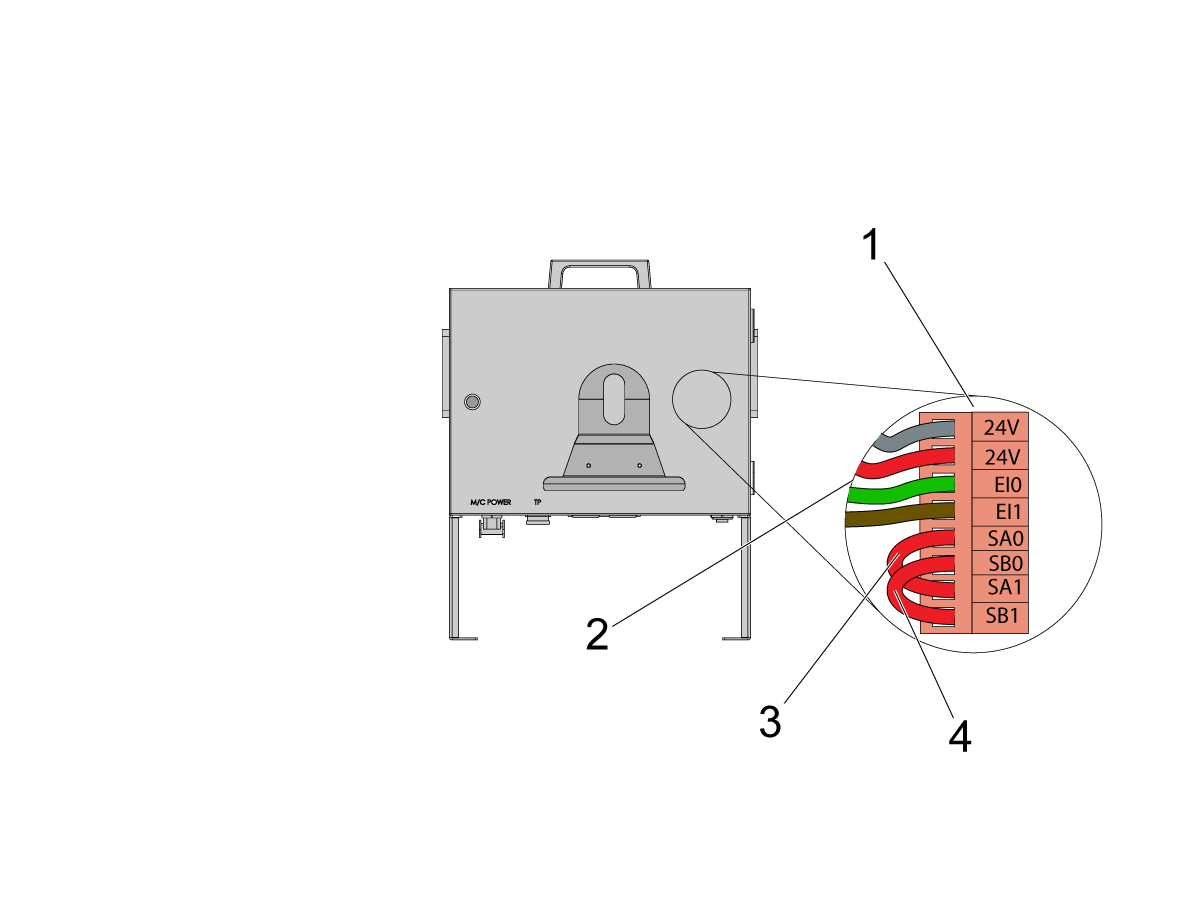
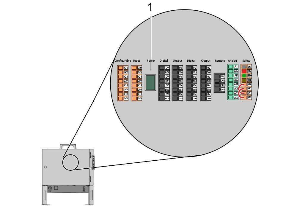
    Unutar upravljačke kutije kobota ugradite dio kabela za signale robota (33-1272 ili 33-1351).  Da biste to učinili, uklonite sigurnosni priključak [1] iz upravljačke kutije kobota kako biste ugradili različito obojene žice u njihove odgovarajuće lokacije

    33-1272 / 33-1351 kabeli [2] koji idu na sigurnosni priključak:

    • Siva žica na vrh 24 V
    • Crvena žica na dno 24 V
    • Zelena žica na EI0
    • Smeđa žica na EI1
    • Prespojnik [3] s SA0 na SA1
    • Prespojnik  [4] s SB0 na SB1

     NAPOMENA: Ostale žice iz ovog kabela se ne koriste. Stavite električni izolir na svaki kraj žice i svežite zajedno preostale nekorištene žice. 

    5

    Važno: Nakon ugradnje svih kabela iz kabela signala robota, pobrinite se da osigurač [1] ostane ugrađen cijelo vrijeme kako bi zaštitio upravljačku kutiju kobota.

    6

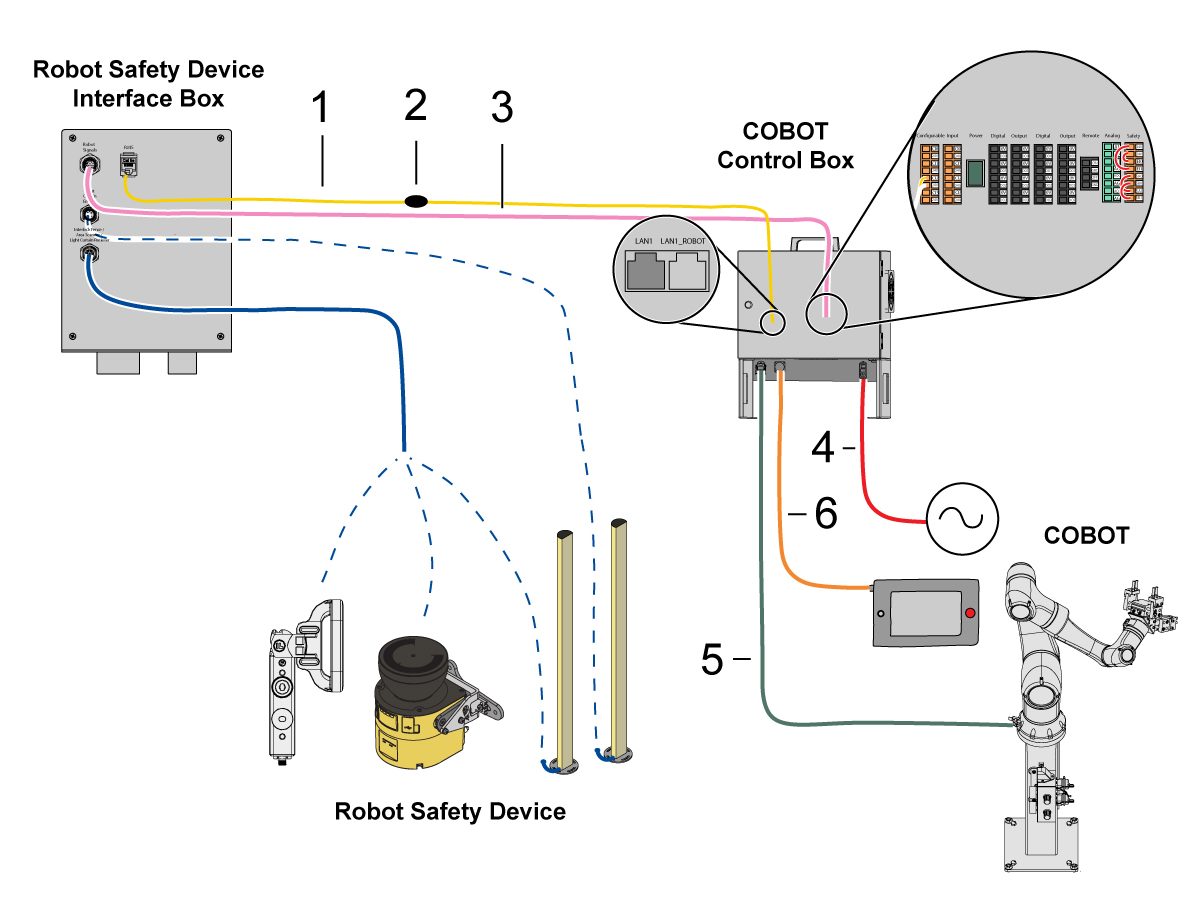
    Spojite kobot na kutiju sučelja:

    Spojite RJ45 ethernet kabel [1] iz upravljačke kutije kobota na kutiju sučelja. Dodajte feritni filtar [2] na RJ-45 kabel.

    Spojite kabel signala robota [3] iz upravljačke kutije kobota na kutiju sučelja. 

    Spojite 120 VAC napojni kabel kobota [4] na vanjski izvor napajanja. 

    Spojite kabel napajanja robota [5] iz upravljačke kutije na kobot.

    Spojite kabel upravljačke ploče za podučavanje [6] iz upravljačke kutije na upravljačku ploču za podučavanje. 

    NAPOMENA: Za više informacija o ugradnji zaporne ograde, skenera područja ili svjetlosne zavjese, pogledajte odjeljak Sigurnosni uređaj robota u nastavku.

    7

    Provjerite je li daljinsko ručno kolo ugrađeno na stroj.

    NAPOMENA: Za više informacija o instalaciji RJH-XL, pogledajte Daljinska ručica za ručno pomicanje - Dodirna velika (RJH-XL) - Instalacija - AD0533. 

    8

    Koraci 7 do 10 su upute za ožičenje i provođenje crijeva za pneumatske hvataljke. Pogledajte odjeljak ugradnje hvataljki niže na ovoj stranici za mehaničku ugradnju.

    Ugradite sklop dvostrukog zračnog solenoida na bočnu stranu postolja, ostavljajući dovoljno slobodnog prostora za crijeva za zrak. Provjerite jesu li u položaju u kojem neće biti na putu. Provedite crijevo za zrak [1] ispod stroja natrag prema CALM ormariću kako je prikazano.

    9

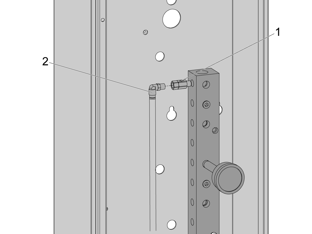
    Unutar CALM ormarića, uklonite čep iz jednog od priključaka CALM razdjelnika i ugradite nepovratni ventil [1] (58-1863) na priključak. Provedite ulazni dovod zraka [2] od sklopa dvostrukog zračnog solenoida (iz prethodnog koraka) u CALM ormarić i spojite dovod zraka na nepovratni ventil.

    Uključite dovod zraka za stroj.

    10

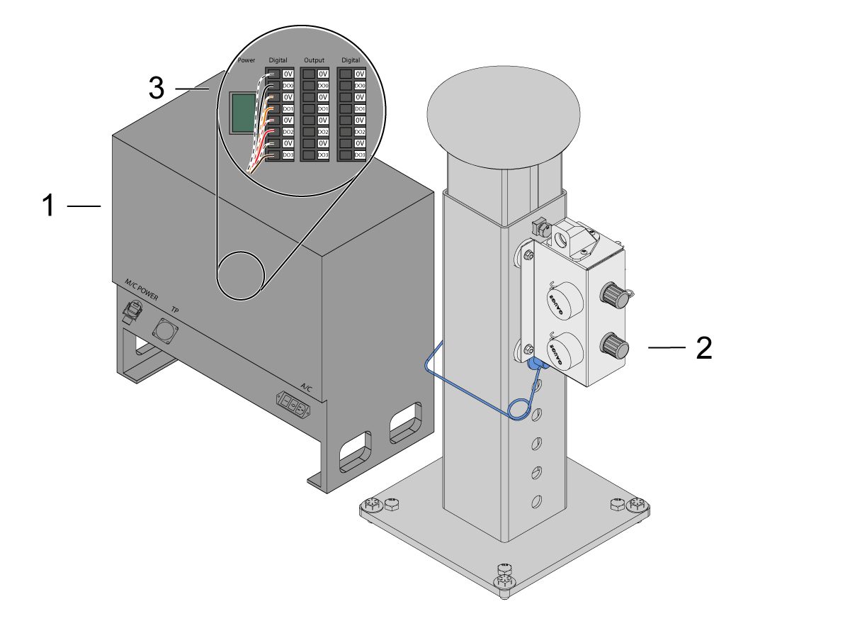
    Pobrinite se da ISKLJUČITE napajanje upravljačke kutije [1].

    Spojite kabel solenoida sa sklopa dvostrukog zračnog solenoida [2] na Digitalni izlaz na upravljačkoj kutiji kobota [1]. Uklonite priključak iz upravljačke kutije kobota.

    11

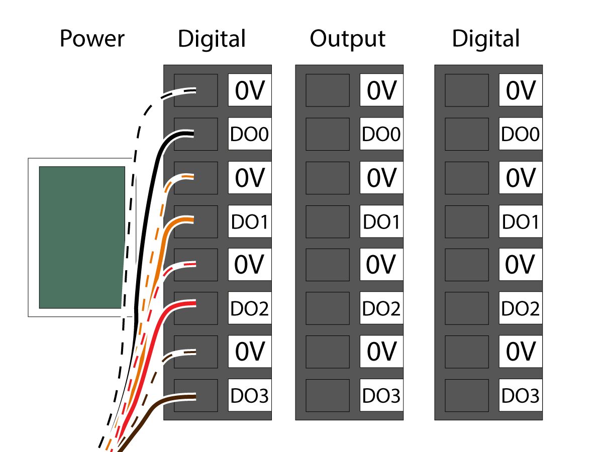
    Spojite kabel napajanja solenoida hvataljke (33-1276 / 33-1341) na priključak Digitalnog izlaza unutar upravljačke kutije. Ugradite različito obojene žice u njihova odgovarajuća mjesta:

    • Crno/bijeli kabel u 0V
    • Crni kabel u DO0
    • Narančasti/bijeli kabel u 0V
    • Narančasti kabel u DO1
    • Crveni/bijeli kabel u 0V
    • Crveni kabel u DO2
    • Smeđi/bijeli kabel u 0V
    • Smeđi kabel u DO3

    Uključite upravljačku kutiju.

    Robot Safety Device

    VAŽNO: NEMOJTE KORISTITI ROBOTA DOK NISTE PRAVILNO KONFIGURIRALI I TESTIRALI RAD SIGURNOSNOG UREĐAJA.

    Svjetlosna zavjesa:

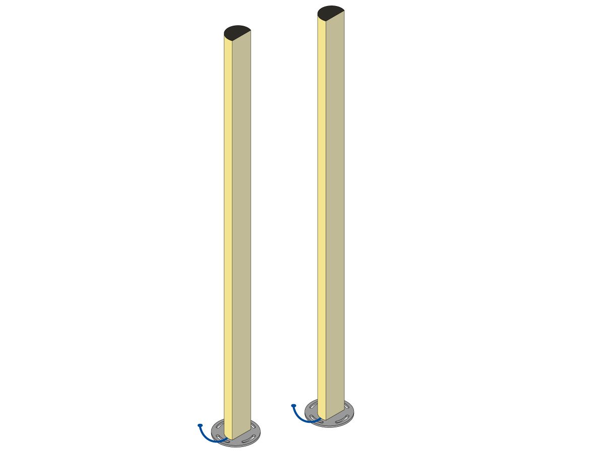
    Kobot paketi dolaze s odašiljačem i prijemnikom svjetlosne zavjese kao zadanim sigurnosnim uređajem. Slijedite postupak u nastavku za instalaciju svjetlosne zavjese: 

    Postavljanje svjetlosne zavjese

    NAPOMENA: Ako je naručen skener područja ili HC10 komplet spreman za ugradnju na stroj, bit će uključeni prijemnik i odašiljač svjetlosne zavjese od 1M. Oni dolaze sa svim kobotima.

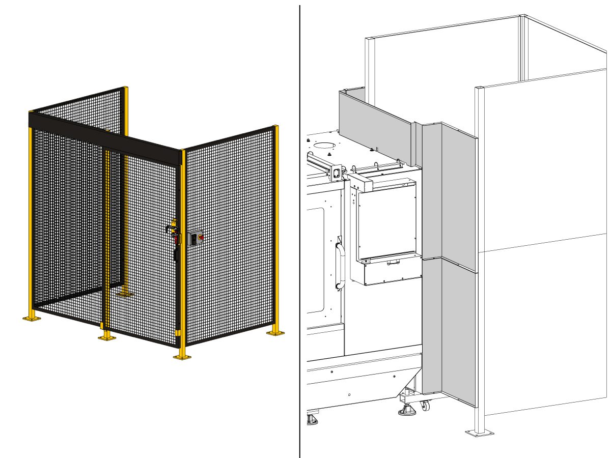
    Robotska ograda:

    Ako je stroj došao opremljen opcijom ograde, sklop robotske ograde i zapor vrata treba ugraditi na stroj. Slijedite postupak za ugradnju u nastavku:

    Instalacija ograde robota

    Nakon instaliranja ograde, instalirajte ploču ograde između stroja i ograde robota.

    Skener područja:

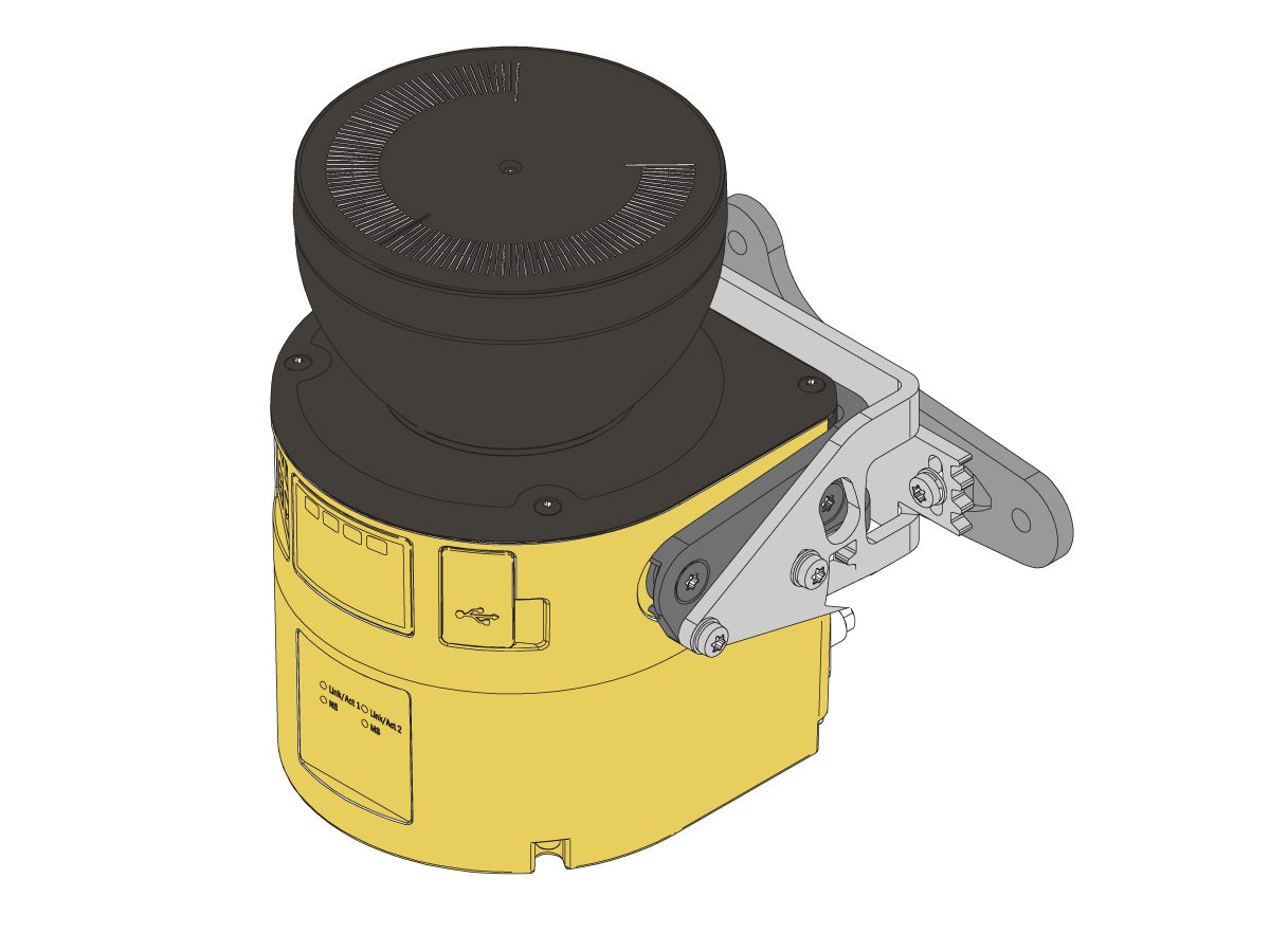
    Ako je stroj došao opremljen opcijom skenera područja, skener područja treba ugraditi i konfigurirati za prostor. Slijedite postupak za ugradnju u nastavku: 

    Instalacija skenera područja

    First Power-UP

    1

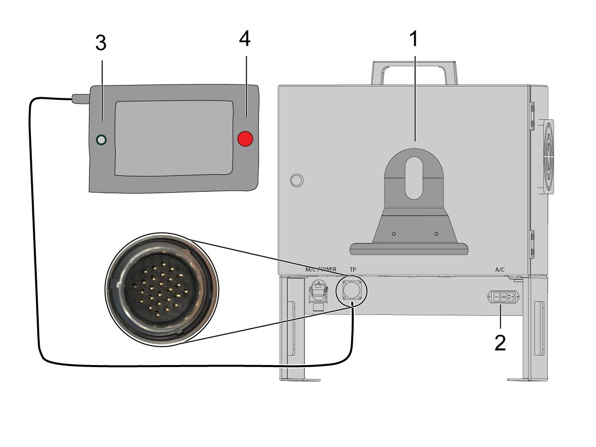
    Instalirajte držač privjeska (ručnog kola) za obuku [1] na prednju stranu upravljačke kutije kobota. 

    Uključite Haas stroj. 

    Uključite upravljačku kutiju kobota okretanjem prekidača za napajanje [2].

    Uključite privjesak (ručno kolo) za obuku kobota pritiskom na krug [3]. 

    Pobrinite se da je E-STOP [4] na privjesku (ručnom kolu) za obuku kobota otpušten. 

    2

    Napomena: privjesak (ručno kolo) za obuku Kobota imat će skočni prozor koji traži unos korisničkog imena I lozinke. Za prijavu na privjesak (ručno kolo) za obuku koristite ove vjerodajnice:

    • Korisničko ime = admin
    • Lozinka = admin

    Uđite u način rada Pokreni. Pritisnite Omogući. 

    Uđite u način rada Ručno pomicanje [1].

    Pomaknite svaki zglob na nultu lokaciju pomoću gumba Pomakni na Nulu [2]. 

    3

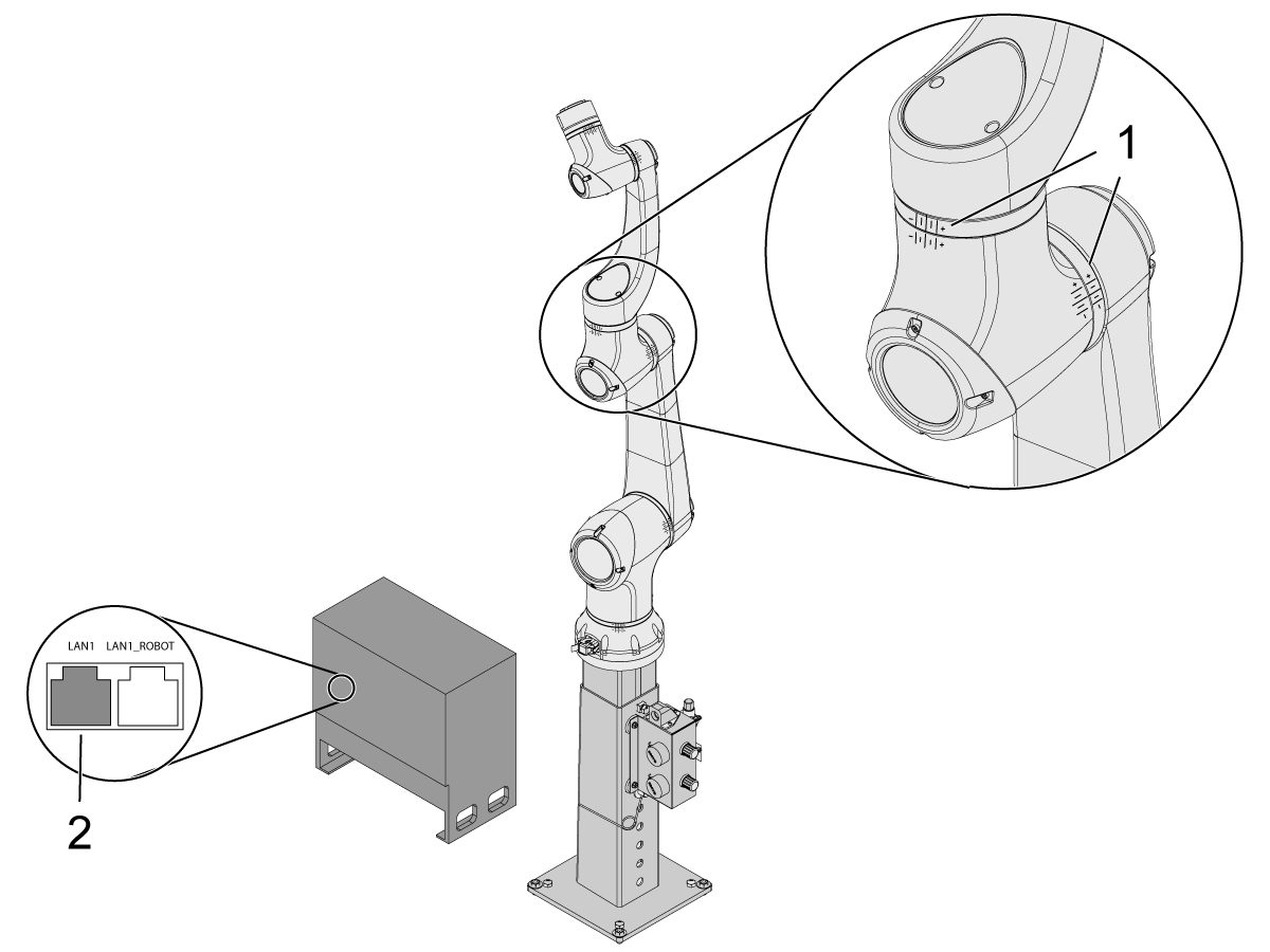
    Kada je robot u nultoj lokaciji, provjerite jesu li hash linije [1] poravnate s obje strane svakog zgloba na kobotu. 

     Važno: Ako bilo koje hash crte zglobova [1] nisu poravnate, ručno pomaknite određeni zglob dok se sve hash crte [1] ne poravnaju. Ova pozicija bit će postavljena u sljedećem koraku kao nova nulta pozicija Kobota.  

    Spojite ethernet kabel [2] iz upravljačke kutije kobota u računalo.

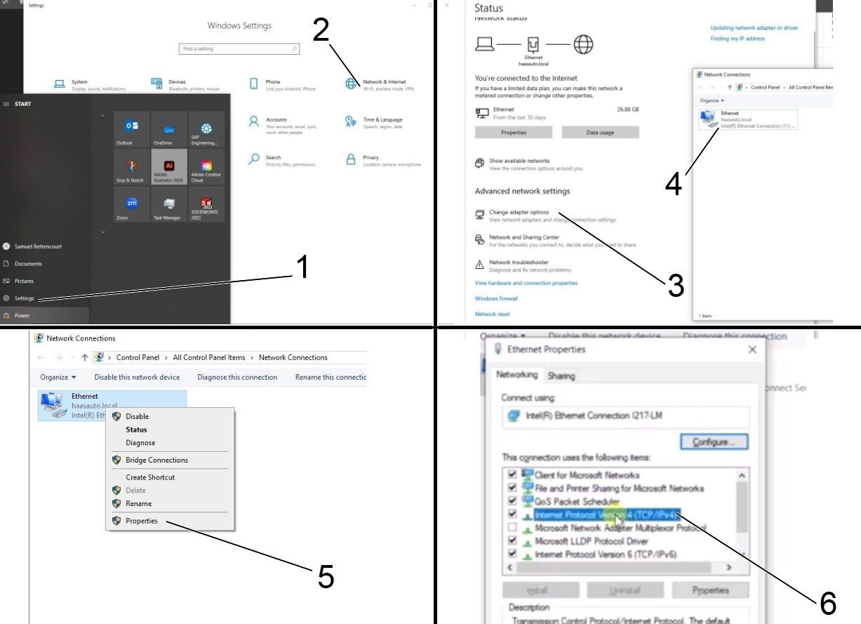
    Na računalu promijenite postavku adaptera da biste omogućili priključak za ethernet. 

    Napomena: Pogledajte sljedeće korake za pomoć pri promjeni postavki adaptera.

    4

    Za promjenu postavki adaptera otvorite stranicu postavki [1] na računalu, a zatim kliknite na Mreža & internet [2] što će otvoriti stranicu statusa mreže.

    Kliknite na Opcije Promijeni prilagodnika [3], a zatim kliknite desno na Ethernet [4] i otvorite prozor svojstva [5]. Od tamo odaberite opciju Internetski protokol Verzija 4 (TCP/IPv4) [6] i kliknite Ok. 


    5

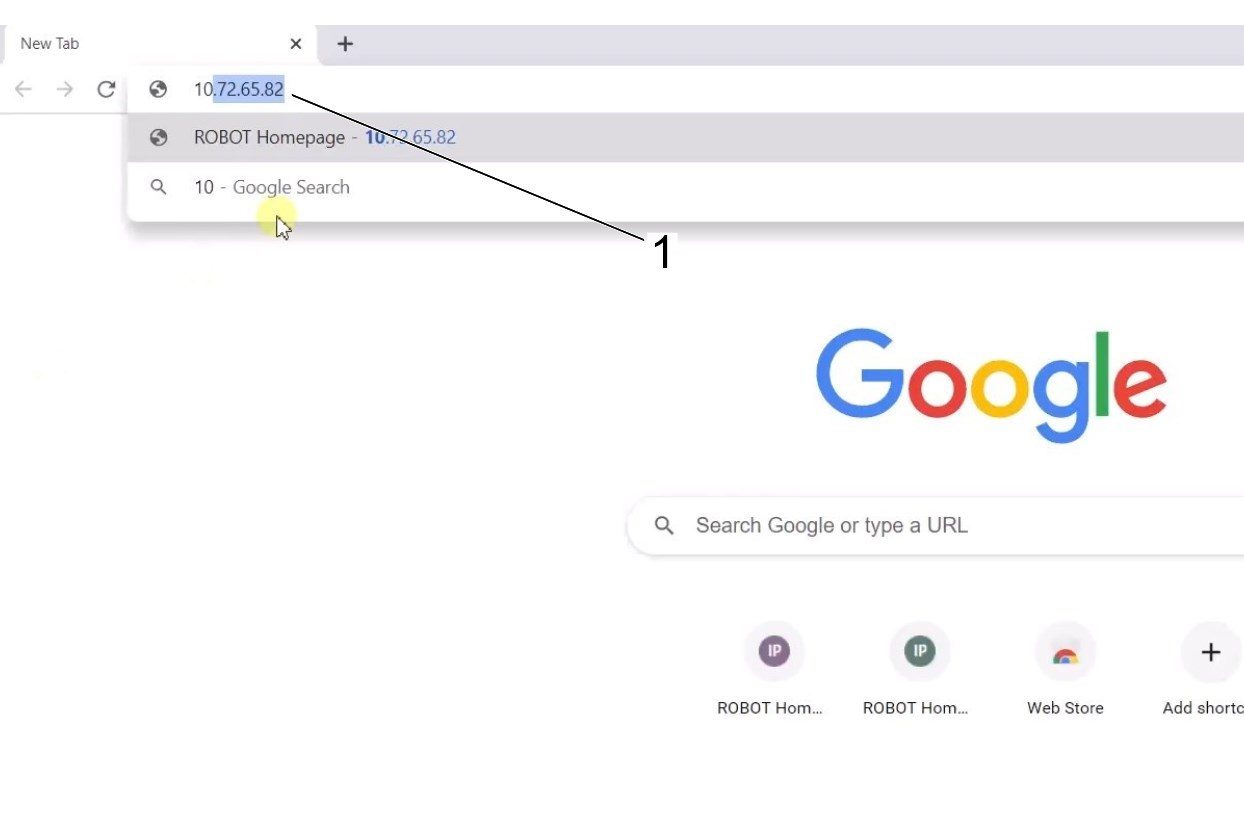
    Postavke etherneta sada će biti točne. Otvorite web preglednik i upišite IP adresu Kobota [1]. 

    Napomena: To je isti postupak kao spajanje prijenosnog računala na HRP-1/2/3. Za više informacija o povezivanju s Kobotom putem etherneta, pogledajte video na stranici HRP-Rješavanje problema koja se nalazi u odjeljku Povezivanje I ručno pomicanje Haas robota. 

    6

    Preuzmite HRTool kroz HBC. U odjeljku Servisa HBC-a, idite na Alati > Dokumenti i Softver > 01 Kontrolni Softver > 01 Upravljački softver Next Generation > 10 kobot Softver > HRTool.zip.

    Raspakirajte mapu i navigirajte do HRToolsMaind.exe.

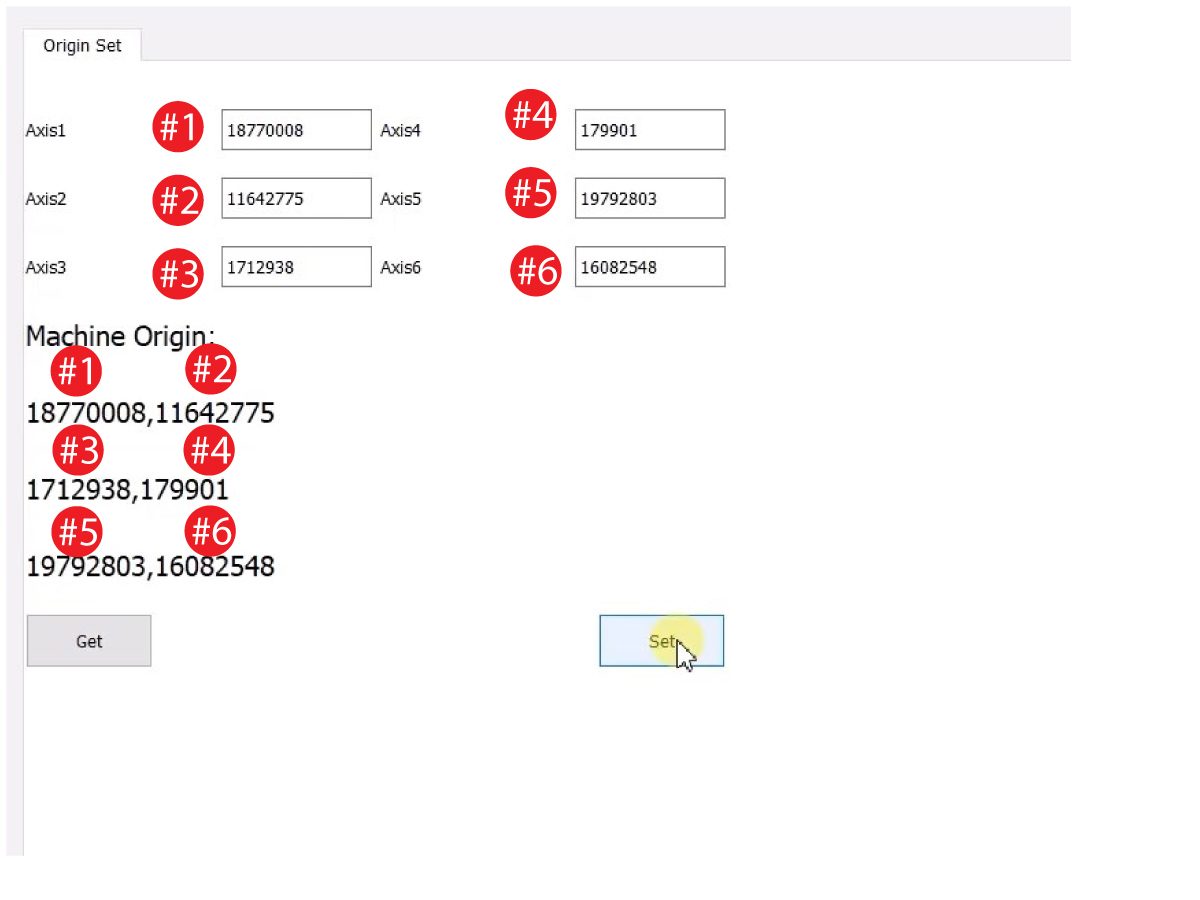
    Umetnite IP adresu kobota koja se nalazi pod karticom Sustavi.  Kliknite Postavi. 

    Idite na karticu Konfiguracija u HRToolu.

    Kliknite "get" da biste vidjeli stvarne nasuprot teoretskim vrijednostima enkodera. 

    Kliknite "set" da postavite teorijske vrijednosti na stvarne vrijednosti enkodera. Ovaj korak postavlja trenutnu poziciju Kobota kao njegovu novu početnu poziciju. 

    7

    Provjerite podudaraju li se stvarne i teorijske vrijednosti enkodera za svaki zglob. 

    NAPOMENA: Ako se vrijednosti ne podudaraju, ponovno pritisnite "Set". 

    8

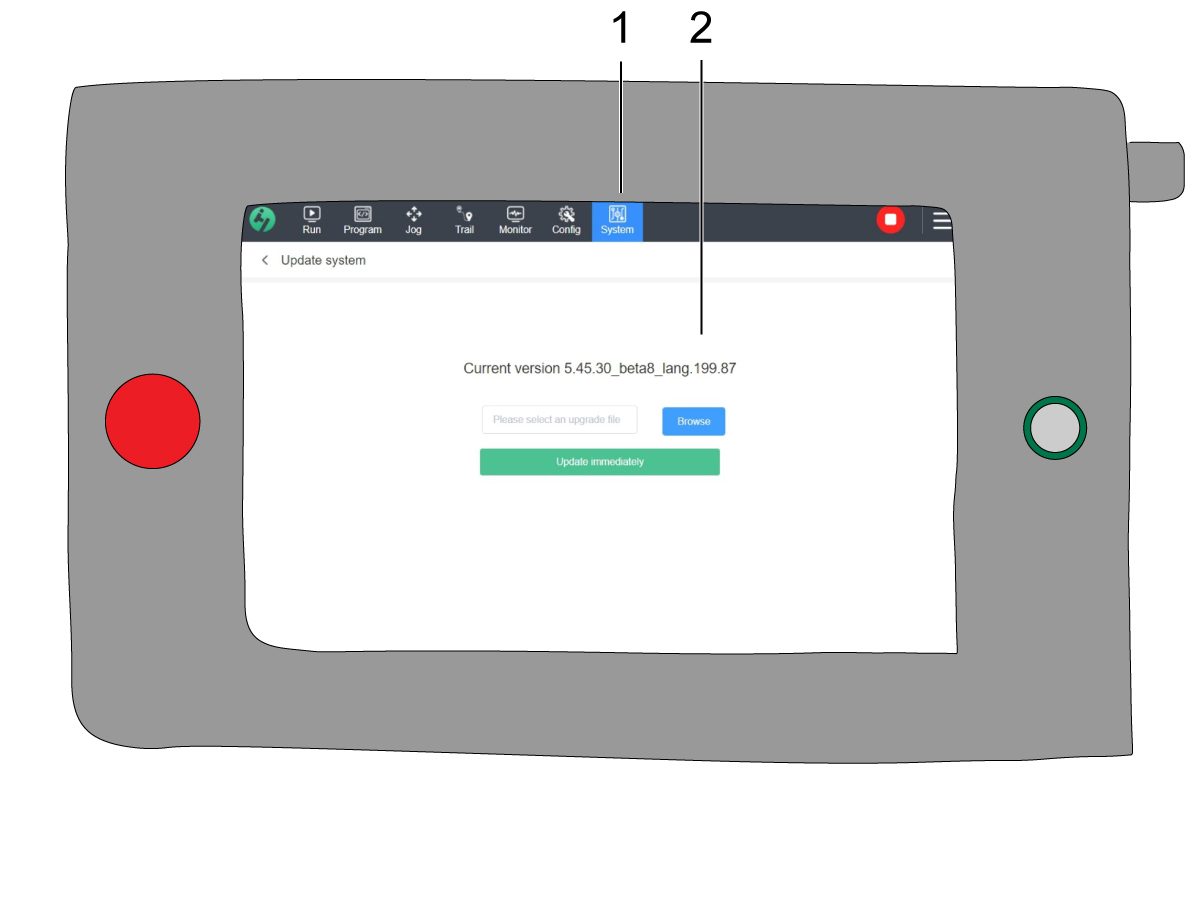
    Na privjesku (ručnom kolu) za obuku, navigirajte do Sustav [1] i zatim Ažuriraj Sustav. 

    Potvrdite da je firmver kobota [2] ili:

    • HR5.51H.16.beta.20231213.zip
    • HR6.4.9.tmp.20240919.zip

    NAPOMENA: Verzija firmvera HR6.4.9.tmp.20240919.zip je kompatibilna s kobotima svih veličina.

    Pogledajte poglavlje Haas kobot - Održavanje za postupak ažuriranja firmvera. 

    9

    Na Haas privjesku (ručnom kolu), vratite sve osi u početnu poziciju.

    Umetnite servisni USB ključ.  Prijeđite na servisni način rada.

    Idite na karticu Parametri> Tvornički.  Promijenite sljedeće:

    • 1278 [1278:] Omogućeno zaustavljanje u nuždi za robota na TRUE
    • 2191 [694:] VRSTA SVJETLOSNE ZAVJESE na LC_TYPE_1
    • 2195 [:] Omogući Desna vrata potpuno otvorena prekidač na ISTINITO
    • 2196 [:] Omogućite prekidač Lijeva vrata potpuno otvorenana na TRUE
    • 2192 [:] Light Curtain Trigger Threshold na 0

    Pritisnite [SETTING].

    Postavite postavke:

    • 372 - Vrsta sustava za dodavanje sirovca na 3: Robot.
    • 376 - Omogućena svjetlosna zavjesa na On

    10

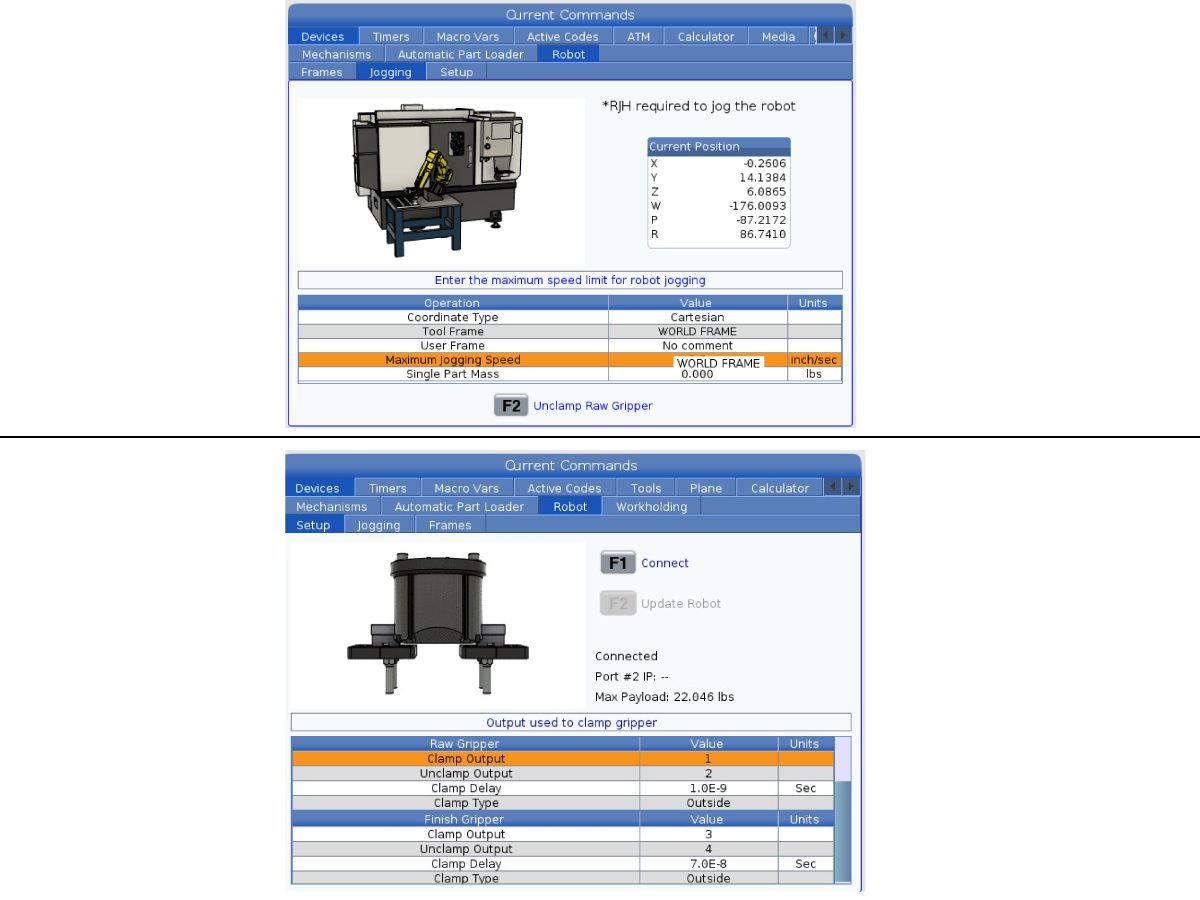
    Na Haas privjesak (ručno kolo) pritisnite [CURRENT COMMANDS].

    Idite na karticu Uređaji>Robot>Ručno pomicanje . Promijenite sljedeće:

    • Maksimalna brzina ručnog pomicanja do 7,9  inča/sek.

     Napomena: Inkrementi ručnog pomicanja na RJH-u su postotak ove maksimalne vrijednosti brzine. Da biste smanjili udaljenost koju robot prelazi sa svakim pomakom kotačića za ručno pomicanje, trebate promijeniti svoju Maksimalnu brzinu ručnog pomicanja na nižu vrijednost.

    Idite na karticuPostavljanje . Promijenite sljedeće:

    • Maksimalna brzina robota do 118 in/s (2000 mm/s). 
    • Unesite neto masu hvataljke. Pogledajte nacrte rasporeda na našoj web stranici (Nacrt rasporeda jednostruke hvataljke ILI Nacrt rasporeda dvoostruke hvataljke) za točnu vrijednost ove postavke.

    UPOZORENJE: Postavljanje ove vrijednosti netočno može uzrokovati da se robotska ruka ne kreće ispravno. 

     
    • Broj hvataljki na broj hvataljki.
    • Izlaz hvataljke za stezanje sirovca na 1
    • Izlaz hvataljke za otpuštanje sirovca na 2.
    • Odgoda stezanja sirove čeljusti na trajanje stezanja / otpuštanja u sec.
    • Vrsta stezanja sirove čeljusti na OD/ID.
    • Izlaz hvataljke za stezanje gotovog komada na 3.
    • Izlaz hvataljke za otpuštanje gotovog komada na 4.
    • Odgoda stezanja završnog prihvata na trajanje stezanja/otpuštanja u sek.
    • Vrsta stezanja sirove čeljusti na OD/ID.

    Isključivanje privjeska (ručnog kola) za obuku

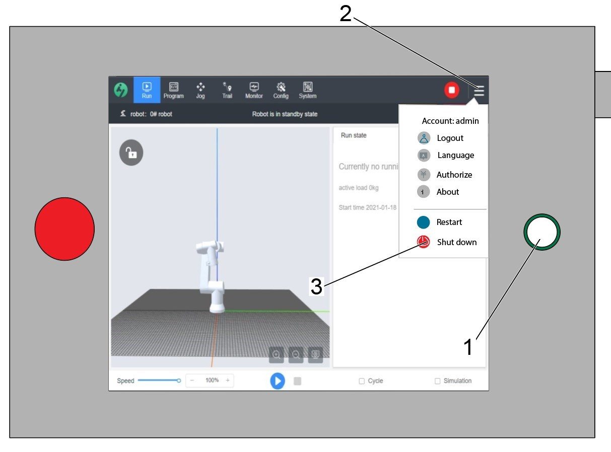
    UPOZORENJE: Nemojte koristiti gumb za napajanje [1] na privjesku (ručnom kolu) za obuku da biste ju isključili. To može uzrokovati gubitak sistemskih datoteka unutar upravljačke kutije kobota.

    Za isključivanje privjeska (ručnog kola) za obuku, pritisnite 3 linije u gornjem desnom kutu [2] da biste otvorili izbornik opcija na desnoj strani.

    Odaberite opciju Isključivanje [3] za pokretanje slijeda isključivanja za kobotsku upravljačku kutiju.

    Važno: Nepravilno isključivanje privjeska (ručnog kola) za obuku može dovesti do oštećenja kritičnih datoteka na upravljačkoj kutiji kobota. To bi moglo rezultirati neuporabljivim kobotom dok se sistemske datoteke ne reinstaliraju u upravljačku kutiju.


    Security Risk Level

    1

    VAŽNO: Pobrinite se da provedete odgovarajuću procjenu rizika i zadovoljite sve odgovarajuće sigurnosne zahtjeve. 

    2

    Na temelju procjene rizika, postavite odgovarajuću razinu sigurnosnog rizika na privjesku (ručnom kolu) za obuku kobota. Idite na Konfig > Opća ograničenja i dodirnite željenu razinu sigurnosnog rizika [1] od 0 - 5.

    Upotrijebite kôd  "admin" u sigurnosnoj provjeri za promjenu razine sigurnosti.

    NAPOMENA: Kada je razina sigurnosnog rizika niža, robot će imati nižu maksimalnu brzinu, silu, itd. Kada je razina sigurnosnog rizika viša, robot će imati višu maksimalnu brzinu, silu, itd. 

    Ova razina sigurnosnog rizika će izračunati maksimalno dopuštenu silu, brzinu, snagu, momentum, brzinu lakta i silu lakta [2] koje će kobot izdržati prije nego što se aktivira alarm 9150.10017 Pogreška zaustavljanja zbog sudara. 

    VAŽNO: Programirana brzina robota ne može biti veća od dopuštene brzine za razinu sigurnosnog rizika. 

    NAPOMENA: Za više informacija o alarmima, pogledajte Haas kobot - Vodič za rješavanje problema. 

    Activation

    1

    Preuzmite i učitajte konfiguracijske datoteke prijavljujući se na HAAS SERVICE PORTAL.

    Preuzmite konfiguracijske datoteke za sigurnosnu automatizaciju prednjeg/bočnog pristupa.

    Učitajte opciju konfiguracijske datoteke zakrpe za upravljačku jedinicu. Pogledajte postupak UPRAVLJAČKA JEDINICA SLJEDEĆE GENERACIJE - KONFIGURACIJSKA DATOTEKA- PREUZIMANJE/UČITAVANJE.

    2

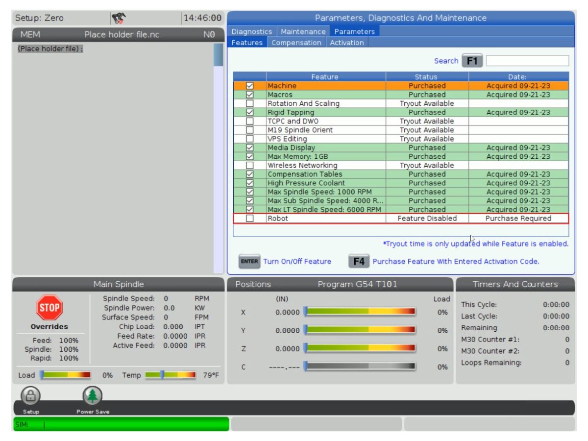
    Idite na Parametri > Značajke > Robot kako biste provjerili je li se značajka robota pojavila na dnu.

    3

    Pritisnite[POWER OFF].

    Idite na karticu Uređaji>Robot>Postavljanje [1].

    Pritisnite[E-Stop].

    Pritisnite [F1]za spajanje robota [2].

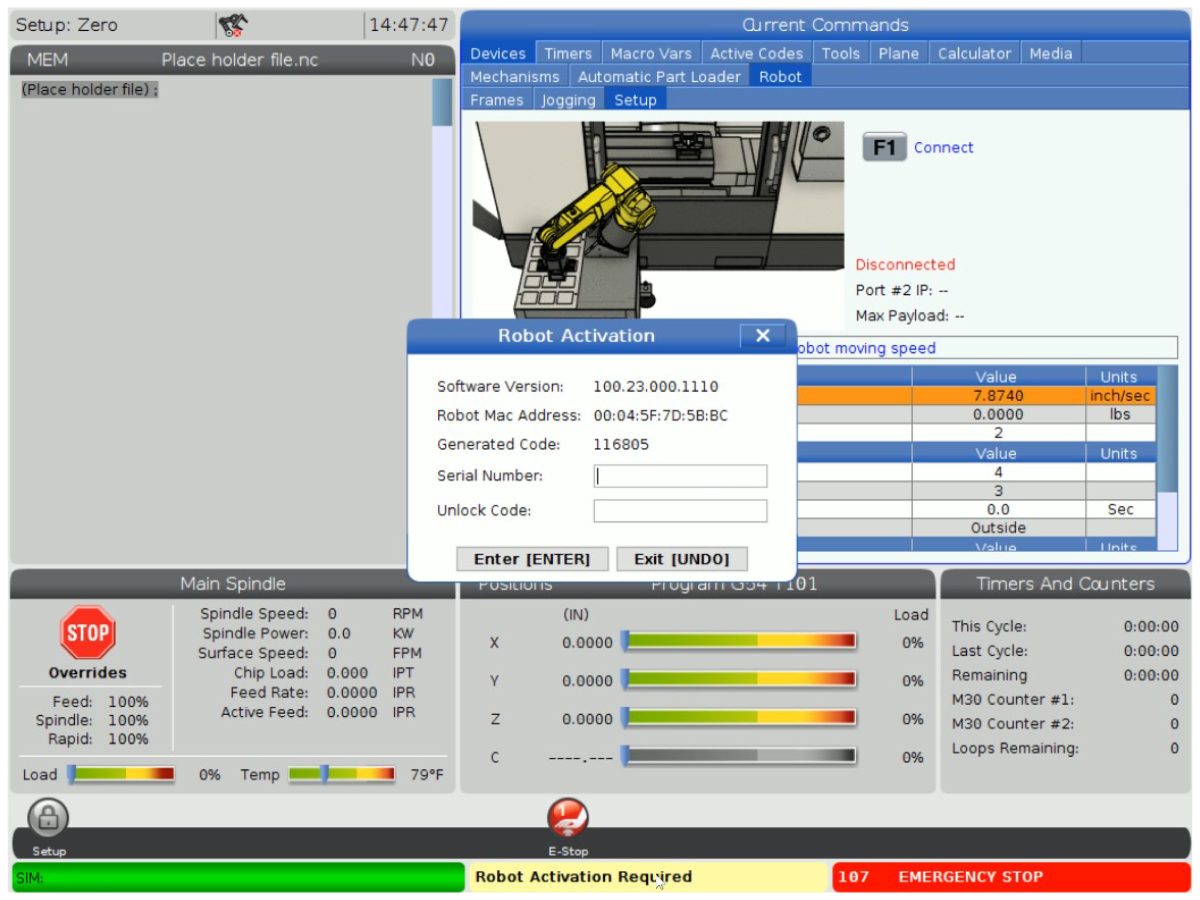
    Prilikom prvog povezivanja robota sa strojem, značajka robota mora se otključati. Ovaj skočni prozor prikazuje trenutnu verziju softvera stroja, MAC adresu robota i generirani kod. Unesite ove informacije u HBC kako biste dobili kod za otključavanje.

    4

    Na HBC-u, idite na karticu Servis [1].

    Na lijevoj strani zaslona kliknite na Aktivacija [2], a zatim odaberite Instalacija kobota [3] da biste započeli postupak za dobivanje koda za otključavanje kobota.

    Prvi korak je unos Serijskog broja stroja [4] i Serijskog broja kobota [5] u polja na HBC-u.

    Nakon što ste unijeli točne informacije, pritisnite Sljedeće [6] u donjem desnom kutu i nastavite kroz korake dok ne primite kod za otključavanje.

    Napomena: Provjerite jeste li na kartici Instalacija kobota [3], a ne na kartici Instalacija robota. Robot instalacija se koristi samo za Haas Robot pakete. Korištenje Robot instalacija za Haas kobote rezultirat će nevažećim kodom za otključavanje.

    5

    Unesite Haas serijski broj kobota[1] i kôd za otključavanje za povezivanje robota sa strojem. 

     Napomena: Ovaj korak može izvršiti samo servisni tehničar HFO-a.

     Napomena: Stroj treba aktivirati prije aktiviranja robota. Slijedite postupak  Aktivacija stroja / Produženje vremena - NGC .

    Kada se robot poveže sa strojem, žuta poruka koja kaže Aktivacija robota uspješna trebala bi se pojaviti na dnu Haas zaslona.

    6

    Otpustite [E-STOP] i pritisnite RESET za brisanje alarma. 

    Pritisnite gumb .

    Pritisnite [CURRENT COMMANDS]  i idite na karticu Uređaji > Robot > Ručno pomicanje.

     Napomena: Robot se u načinu pripreme može pomicati samo kotačićem, dok je F2 RJH pritisnut. Pogledajte Način postavljanja/pokretanja u nastavku.

    Na daljinskom upravljaču za ručno pomicanje pritisnite gumb Zglob (Joint) da biste ušli u Koordinate zglobova.

    Pomaknite robota na dostupnu lokaciju za ugradnju hvataljki.

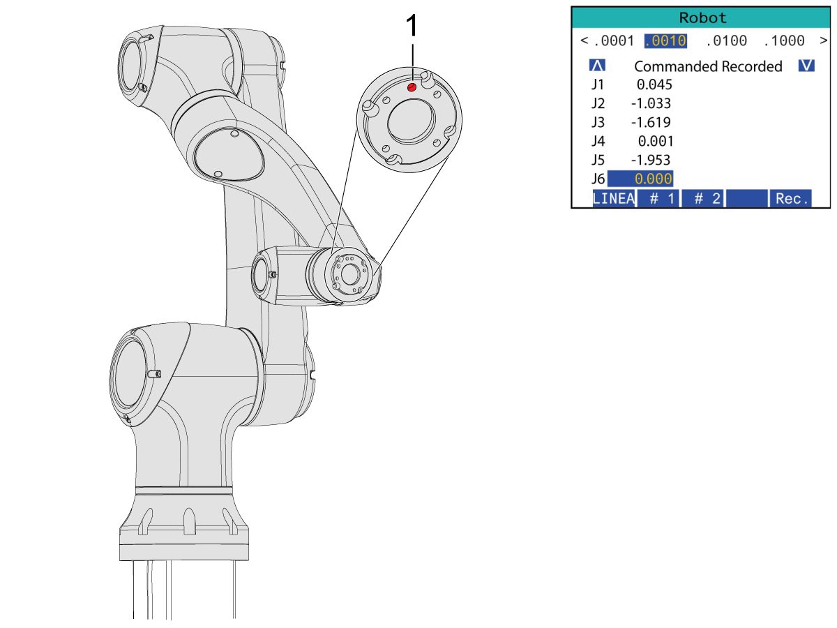
    Ručno pomaknite J6 u položaj 0.0000.

    Otvor lokacije trebao bi biti centriran na vrhu.

    Napomena: Pritisnite [Emergency Stop] prije rada na robotu.

    Gripper Installation

    1

    Isključite dovod zraka za stroj okretanjem ventila u ormariću Zrak/Podmazivanje i povucite ventil za odušak pritiska zraka u sustavu.

    2

    Za hvataljke s dvostrukim djelovanjem:

    Postoje dvije verzije dvostrukih hvataljki za ovaj odjeljak, a obje imaju isti postupak ugradnje.

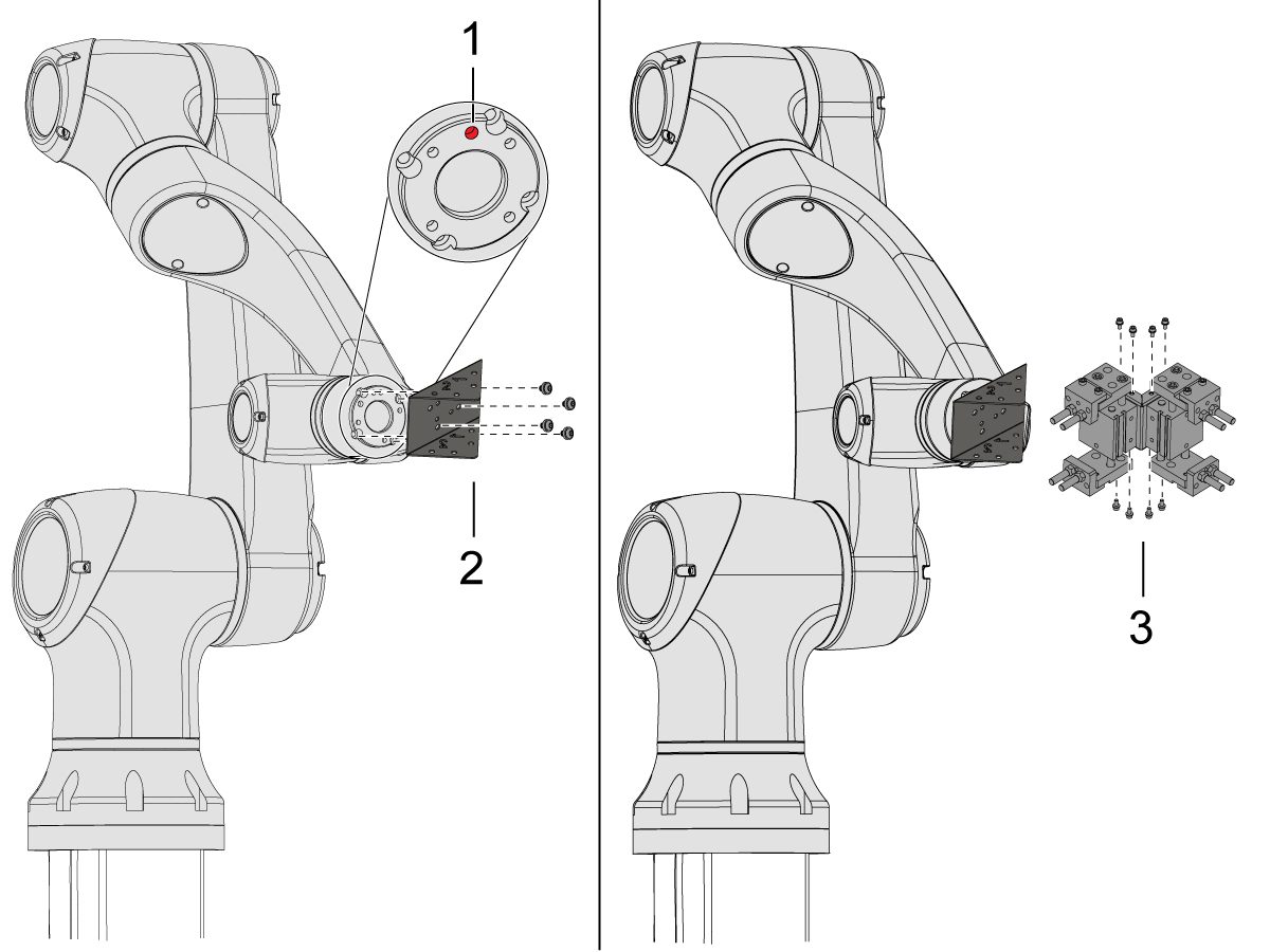
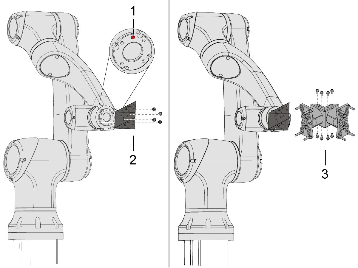
    Ručno pomaknite robot tako da rupa lokacije [1] bude centrirana na vrhu.

    Ugradite priključnu ploču [2] na kraj robotske ruke.

    Ugradite sklop dvostruke hvataljke [3] na priključnu ploču [2].

    NAPOMENA: Pazite da instalirate hvataljku 1 (koja ima narančaste i ljubičaste vezice) na segment priključne ploče hvataljke 1. 

    3

    Za kutnu jednostruku hvataljku:

    Ručno pomaknite robot tako da rupa lokacije [1] bude centrirana na vrhu.

    Ugradite kutnu priključnu ploču [2] na kraj robotske ruke.

    Ugradite sklop jednostruke hvataljke [3] na priključnu ploču [2].

    4

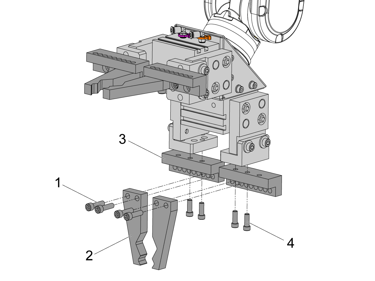
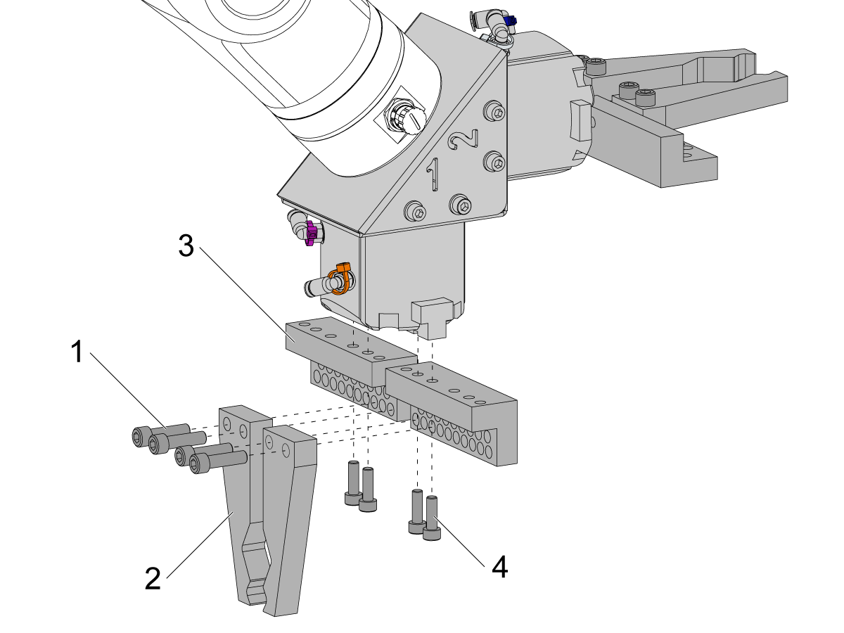
    Za ugradnju prstiju hvataljki šipke, uklonite ploče hvataljki s tijela hvataljki.

    Ugradite ploče s vijcima za hvataljke šipki [3] pomoću (x8) SHCS M6 vijaka [4]. Stegnite na 10 ft-lbs.

    Ugradite prste za hvataljke šipki [2] pomoću (x8) SHCS 1/4-20 vijaka [1]. Stegnite na 13 ft-lbs.

    5

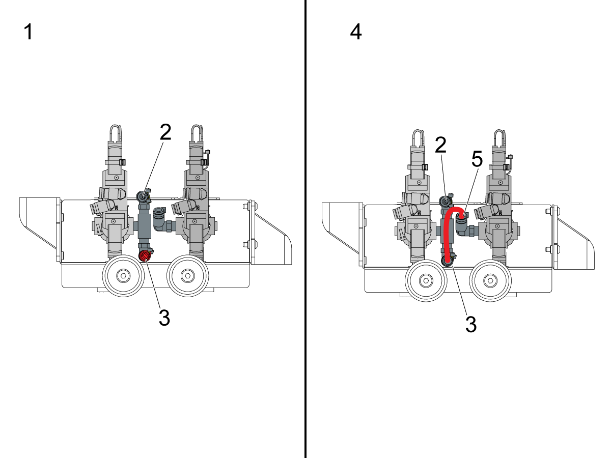
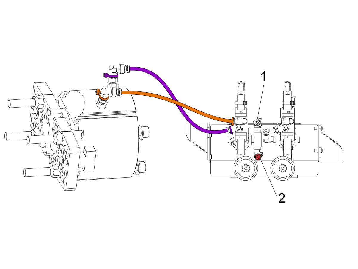
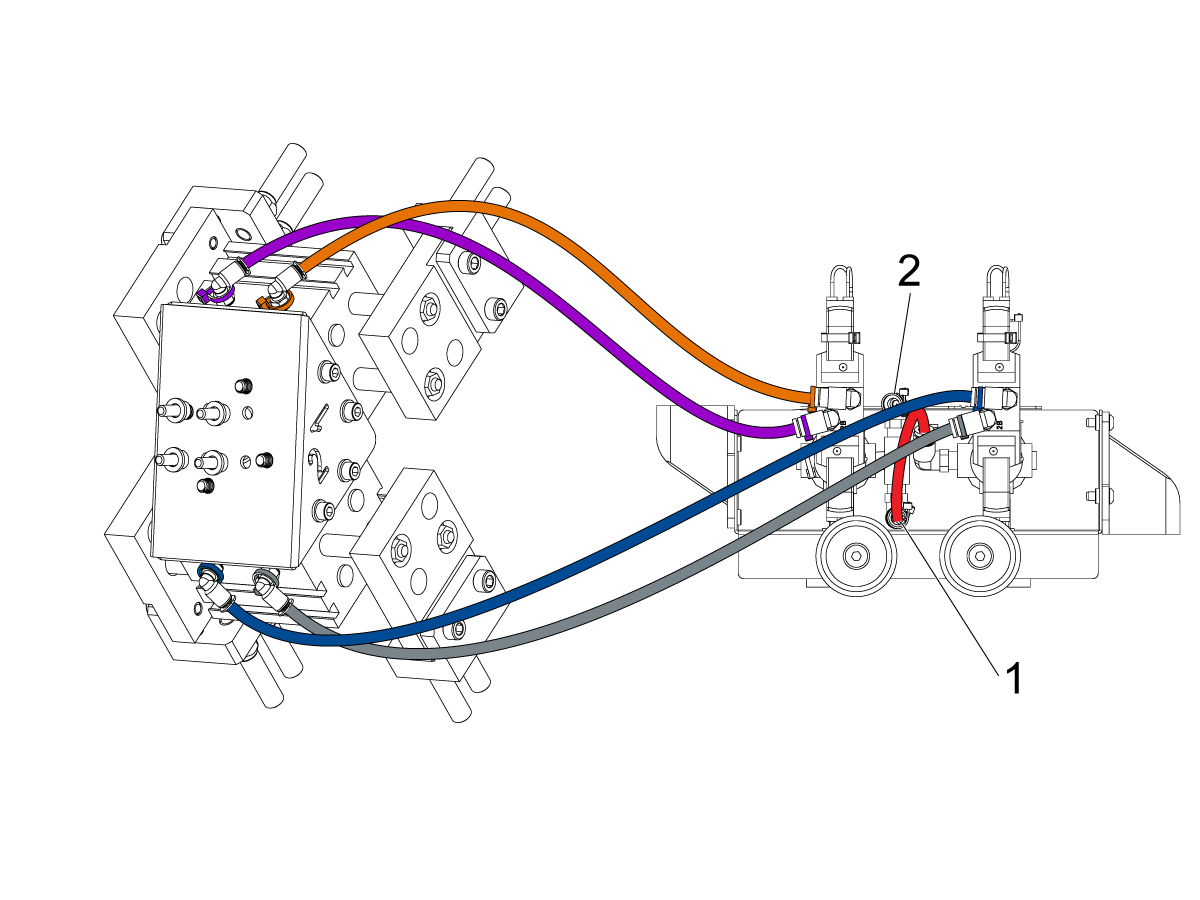
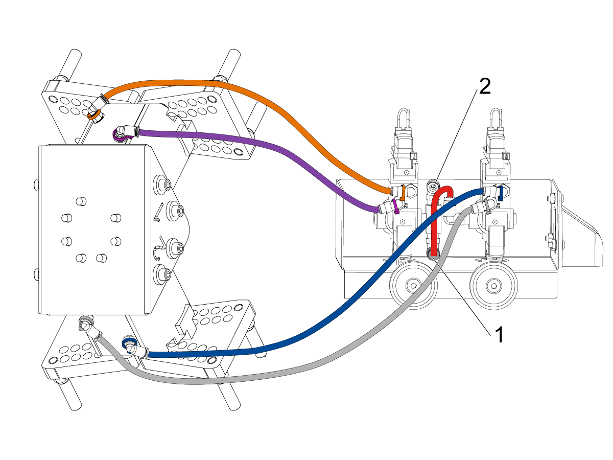
    Konfigurirajte sklop dvostrukog solenoida zraka koji se koristi za pneumatske hvataljke ovisno o konfiguraciji s jednostrukom [1] ili dvostrukom [2] hvataljkom. 

    Za jednostruke hvataljke [1], spojite dolazni zrak na priključak [2] i držite čep na drugom kraju priključka [3] kako je prikazano na slici.

    Za dvostruke hvataljke [4], uklonite čep u priključku [3] i pričvrstite malo crijevo zraka na drugi solenoid [5]. Zatim spojite crijevo ulaznog zraka na priključak [2] tako da oba solenoida primaju zrak.

    6

    Za jednostruku hvataljku:

    Provedite (x2) zračne vodove od hvataljke do priključka u istoj boji na sklopu dvostrukog solenoida za zrak. 

    Pričvrstite zračne vodove tako da ih omotate u kabelski vod. Koristite čičak trake za pričvršćivanje kanalice kabela na Kobot. Pobrinite se da ima dovoljno labavosti tako da kabeli nisu napeti kada je kobot potpuno ispružen.

    Umetnite crijevo zraka na priključak korištenog solenoida [1]. 

    Provjerite je li utikač instaliran na priključak neiskorištenog solenoida [2]. 

    7

    Za dvostruke hvataljke:

    Provedite (x2) zračne vodove od hvataljke br. 1 do priključka u istoj boji na sklopu dvostrukog solenoida za zrak. 

    Provedite (x2) zračne vodove od hvataljke br. 2 do priključka u istoj boji na sklopu dvostrukog solenoida za zrak. 

    Pričvrstite zračne vodove tako da ih omotate u kabelski vod. Koristite čičak trake za pričvršćivanje kanalice kabela na Kobot. Pobrinite se da ima dovoljno labavosti tako da kabeli nisu napeti kada je kobot potpuno ispružen.

    Umetnite kratki dovod zraka [1] koji povezuje prvi solenoid s drugim. 

    Umetnite crijevo zraka na priključak [2]. 

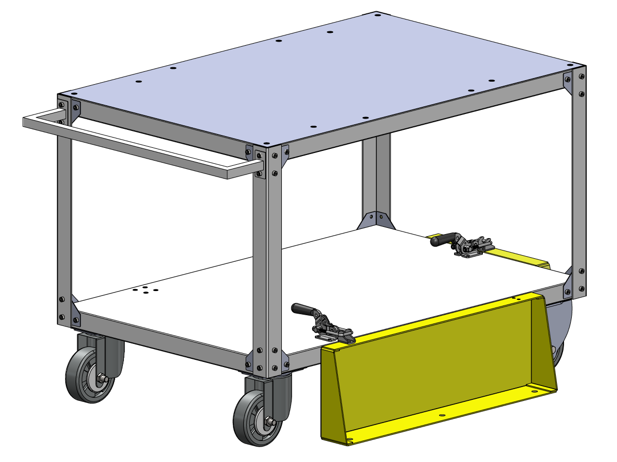
    Parts Table Assembly

    Ako je naručena opcija stola za dijelove, slijedite postupak u nastavku za upute za sastavljanje:

    Haas Robot - Sastavljanje stola za dijelove

    NAPOMENA: Ako je kupljen HC10 KOMPLET SPREMAN ZA UGRADNJU NA STROJ, nema potrebe za instaliranjem kotača ako montirate stol za dijelove izravno na drvenu paletu. 

    Verification

    Testirajte zaustavljanje u nuždi:

    • Pritisnite svaki E-STOP gumb koji se nalazi na Haas privjesku (ručnom kolu), RJH-XL-u i privjesku (ručnom kolu) za obuku kobota. Pazite da stroj generira alarm 107 ZAUSTAVLJANJE U NUŽDI .  Ako gumb Zaustavljanje u nuždi ne generira alarm107 za ZAUSTAVLJANJE U NUŽDI , provjerite ožičenje. Ugradite najnovije konfiguracijske datoteke da biste omogućili RJH-XL.

    Ispitivanje sigurnosnog uređaja robota

    Provjerite da se na Haas upravljačkoj ploči pojavi ikona aktiviranja zaustavljanja u nuždi ili svjetlosne zavjese kada se aktivira sigurnosni uređaj robota. 

    • Ograda - Umetnite ključ u bravu blokade, provjerite jesu li dvije crvene LED lampice na prednjoj strani brave blokade isključene. Izvadite ključ iz blokade, provjerite jesu li dvije crvene LED lampice UKLJUČENE. 
    • Skener područja - Stanite unutar zaštićenog polja, provjerite pali li se crvena LED lampica na skeneru područja. Izađite izvan zaštitnog polja, provjerite svijetli li zelena LED dioda.
    • Svjetlosna zavjesa - Prekinite zrake svjetlosne zavjese, provjerite pojavljuje li se ikona aktivirane svjetlosne zavjese na Haas konzoli. Pritisnite. [RESET] Izađite izvan zraka svjetlosne zavjese, provjerite da se ikona ne pojavljuje na Haas privjesku (ručno kolo). 

    NAPOMENA: Ako se ikona aktivirane svjetlosne zavjese ne prikazuje, provjerite ožičenje, poravnanje i tvorničku postavku: 2191 [694:] VRSTA SVJETLOSNE ZAVJESE je postavljena na LC_TYPE_1.

    Provjerite rad hvataljki:

    • Provjerite stežu li se i otpuštaju obje hvataljke pravilno.
    • Pritisnite [CURRENT COMMANDS]  i idite na karticu Uređaji > Robot > Ručno pomicanje .
    • Pritisnite [F2] za stezanje/otpuštanje završnog prihvata.
    • Pritisnite [F3] za stezanje/otpuštanje Sirove čeljusti.

    Ispitajte daljinsku ručicu za ručno pomicanje osi stroja:

    • Odspojite daljinsku ručicu za ručno pomicanje osi stroja
    • Pritisnite [HANDLE JOG] gumb. 
    • Pritisnite [CURRENT COMMANDS]  i idite na karticu Uređaji > Robot > Ručno pomicanje .
    • Na daljinskom upravljaču za ručno pomicanje pritisnite gumb Zglob (Joint) da biste ušli u Koordinate zglobova.
    • Premjestite robot na sigurno mjesto.

    VAŽNO: Ako se pojavi žuta poruka upozorenja koja kaže "Molimo aktivirajte svjetlosnu zavjesu ili sigurnosnu ćeliju" prilikom pokušaja rukovanja robotom, provjerite je li sigurnosni parametar primijenjen ponovnim učitavanjem konfiguracijskih datoteka s HBC. 

    Provjerite rad sigurnog načina rada/pokretanja

    Svi Haas CNC strojevi su opremljeni prekidačem s ključem na bočnoj strani upravljačke kutije za zaključavanje i otključavanje načina rada pripreme. Robot će imati sljedeća ponašanja ovisno o odabranom načinu rada. 

    • Kada je Haas upravljačka jedinica u načinu rada Pokreni, način 1, aktiviranje sigurnosnog uređaja robota zaustavlja svo kretanje. Ovo kretanje ne može započeti dok sigurnosni uređaj robota više nije aktiviran.
    • Kad je Haas upravljačka jedinica u načinu pripreme, način 2, može se izvršiti pomak ograničene brzine kao što je ručno pomicanje osovine robota u svrhu programiranja putanje pomaka robota, postavljanja položaja podizanja, postavljanja mjesta središta alata robota, (pomak), umetanja i preuzimanja obradaka s glavnog vretena ili držača obratka na stroju itd. Programirana putanja će se također moći sporo pomicati da radi provjere programirane putanje robota. Robot se u načinu pripreme može pomicati samo kotačićem, dok je F2 RJH pritisnut.

    Haas Robot - Quick Start Guide

    Nakon što instalirate robot, postavite zadatak slijedeći sljedeći postupak.

    Haas robot - Kratki vodič za početak rada

    Disable the Robot

    Da biste onemogućili robotu da pokrene stroj u samostalnom načinu rada. Pritisnite [SETTING]. Promijenite sljedeće postavke:

    • 372 - Tip sustava za dodavanje sirovca na 0: Ništa
    • 376 Omogućena svjetlosna zavjesa na isključeno

    5.2 Instalacija tokarilice

    Recently Updated

    Haas Kobot 10 (HC10) - Tokarilica - Instalacija


    AD0715

    Revizija G - 07/2026

    Introduction

    Ovaj postupak pokazat će vam kako ugraditi Haas 10KG kobot (HC10).

    Napomena: Radna ćelija koju je dizajnirao Haas i koja se sastoji od CNC stroja te robot procijenjeni su za usklađenost s CE zahtjevima. Promjene ili varijacije dizajna ćelija tvrtke Haas trebaju se procijeniti u pogledu usklađenosti s primjenjivim standardima i odgovornost su korisnika/integratora.

    Zahtjevi za stroj:

    • 100.24.000.1001 verzija ili novija
    • Verzija
    • HR5.51H.16.beta.20231213.zip ili verzija HR6.4.9.tmp20240919.zip .
    • ST-10/15/20/25/28 & DS-20Y/25Y metalni lim za ponovno pokretanje (ravno čelo)
    • Haas automatska vrata
    • 34-349xB I/O ploča ili novija
    • 93-1000610 DALJINSKA RUČICA ZA RUČNO POMICANJE OSI STROJA S DODIRNIM LCD EKRANOM (RJH-XL) DALJINSKA RUČICA ZA RUČNO POMICANJE OSI STROJA - XL  

     NAPOMENA: Ako stroj ima instaliranu opciju Hvatača dijelova. Spremnik za hvatanje ometat će robota i treba ga ukloniti. Morat će se napraviti prilagođen metalni lim za pokrivanje i brtvljenje otvora.

    Potreban alat:

    • Mali ravni odvijač

    Fixing / Anchoring Requirements

    • The Haas 10KG Cobot (HC10) is configured and sold by Haas with a pedestal/table that is sufficiently stable when used according to Haas defined part size and weight limits. 
    IMPORTANT:  For more information directly on the Hans Cobot, refer to the Hans Robot Operation Manual for Elfin Software.

    There are 3 scenarios in which the cobot option can be installed on a Haas machine:

    1. Cobot option was ordered at the same time as the machine. Both the cobot and the machine are being installed together.
    2. Cobot option is ordered so that it can be installed on a previously installed machine.
    3. Cobot option was previously installed on a machine, but will now be moved to a different Haas machine.

    In scenarios 2 and 3, additional parts will need to be ordered under the Serial Number of the Haas machine. See the tables below for what parts are needed in the different scenarios.

    Scenario 1 - Cobot and Machine are ordered and installed together

    Component Part Number Description
    NO ADDITIONAL PARTS NEED TO BE ORDERED WHEN COBOT AND MACHINE ARE ORDERED TOGETHER

    Scenario 2 - Cobot being field installed on existing Haas Machine

    Component Part Number Description
    CHECK TO SEE IF HAAS MACHINE ALREADY HAS THESE FEATURES & PARAMETERS BEFORE ORDERING
    Robot Feature Unlock Parameter 93-1001031 Kit activates the robot feature on the Haas machine. To check if you need this kit, go to the Features tab on the Haas Control and check if the Robot option is highlighted. This kit does not include any physical parts.
    Load Type Safety Parameters 93-1000997 Front Automation Safety Parameters - Kit is needed when the cobot will be loading parts through the front door of the Haas machine. This kit does not include any physical parts and the autodoor option would need to be purchased and installed separately.
    OR  
    93-1000996 Side Automation Safetly Parameters - Kit is needed when the cobot will be loading parts through the side window of the Haas machine. This kit does not include any physical parts and the autowindow option would need to be purchased and installed separately.

    Scenario 3 - Cobot is being transferred from one machine to a different Haas Machine

    Component Part Number Description
    Cobot Integration Kit See Integration Kit Compatibility Chart Kit is needed to install parts on the Haas machine to interface with the cobot. This includes the interface box, door switches, etc... as well as the Robot Unlock Feature parameter. This kit only needs to be purchased when transferring a cobot to a new Haas machine since these parts are normally included when a cobot is ordered. 
    Load Type Safety Parameters 93-1000997 Front Automation Safety Parameters - Kit is needed when the cobot will be loading parts through the front door of the Haas machine. This kit does not include any physical parts and the autodoor option would need to be purchased and installed separately.
    OR  
    93-1000996 Side Automation Safetly Parameters - Kit is needed when the cobot will be loading parts through the side window of the Haas machine. This kit does not include any physical parts and the autowindow option would need to be purchased and installed separately.
    Safety Device 08-1899 Multi-Sided Light Curtain Kit - Kit is needed if the safety device is NOT going to be transferred from the first machine and the second Haas machine needs it's own safety device. This kit makes a 4-sided protective barrier.
    OR  
    08-1948 5-Sided Light Curtain Kit - Kit is needed when the safety device is NOT going to be transferred from the first machine machine and the second Haas machine needs it's own safety device. This kit makes a 5-sided protective barrier.
    OR  
    08-1987 Laser Area Scanner Kit - Kit is needed when the safety device is NOT going to be transferred from the first machine machine and the second Haas machine needs it's own safety device. This area scanner has a sensing distance of 4meters.

    Lathe Setup

    1

    Isključite stroj.

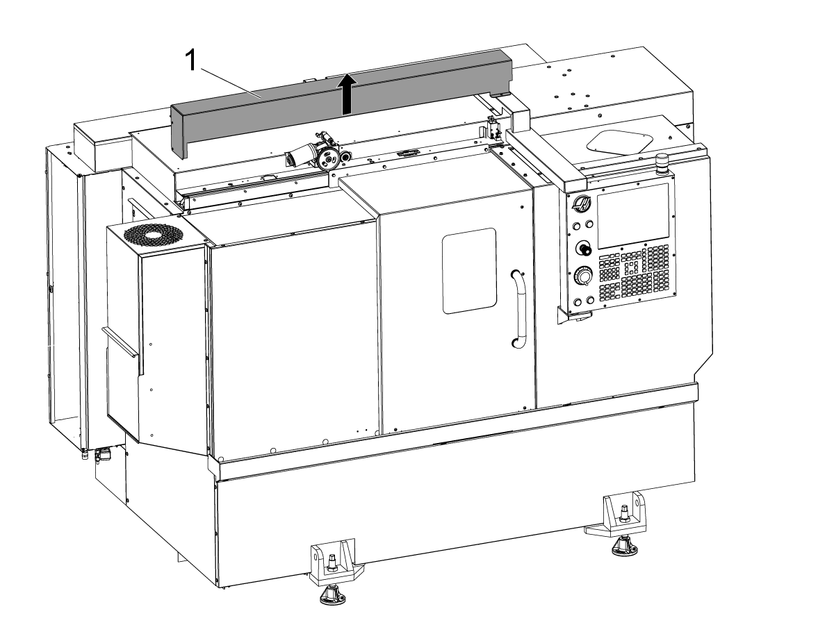
    Uklonite poklopac automatskih vrata [1].

    2

    ST-20/25 & DS-20Y/25Y:

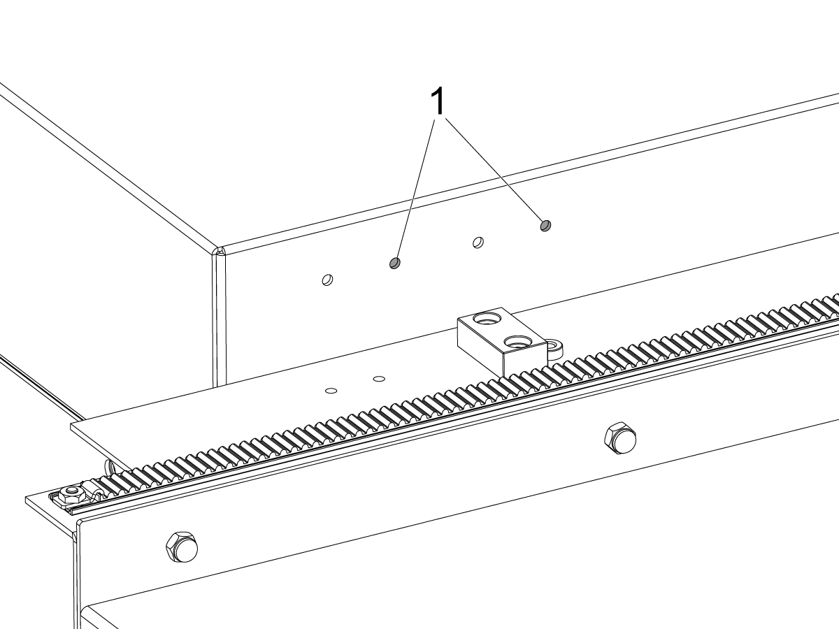
    Za strojeve s otvorima za nosače prekidača na krovnoj ploči. Instalirajte nosač prekidača na desni par rupa[1] za ST-20/25.

    3

    Za strojeve bez otvora za nosače prekidača na krovnoj ploči.

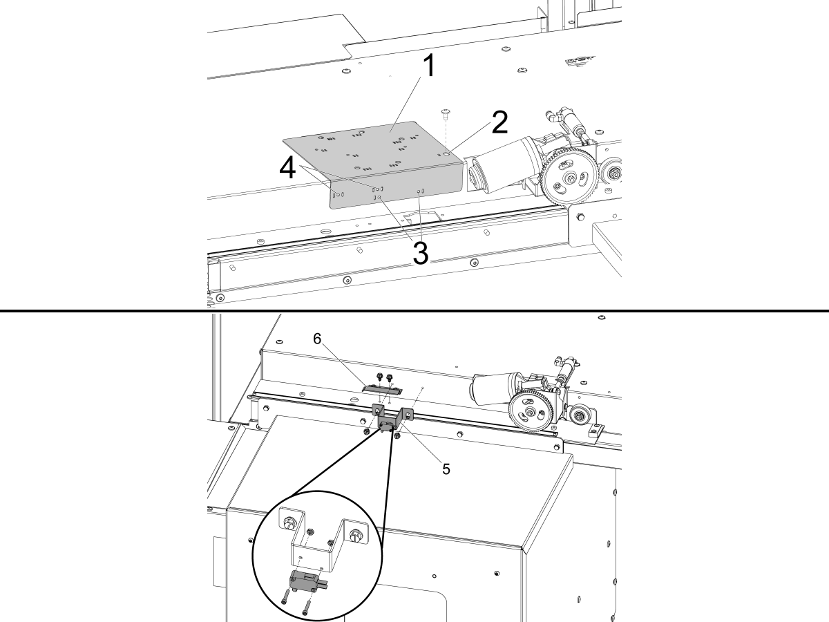
    Koristite priloženu vodilicu za bušenje [1] da izbušite rupe za montažu za statusni prekidač. DOOR FULLY OPEN

    Poravnajte krajnju desnu rupu na vrhu vodilice za bušenje koja je označena jednim utorom [2] s rupom za montažu poklopca automatskih vrata s lijeve strane od motora automatskih vrata i pričvrstite pomoću imbus vijaka.

    ST-10/15:

    • Izbušite dvije rupe za montažu promjera 3/16" (4,7 mm) kroz rupe vodilice za bušenje koje su označene jednim utorom [3].

    ST-20/25 & DS-20Y/25Y:

    • Izbušite dvije rupe za montažu promjera 3/16" (4,7 mm) kroz rupe vodilice za bušenje koje su označene utorima s obje strane [4].

    Koristeći isporučene samonarezne vijke, ugradite DOOR FULLY OPEN sklop prekidača [5] i DOOR FULLY OPEN aktivacijsku zastavicu [6].

    4

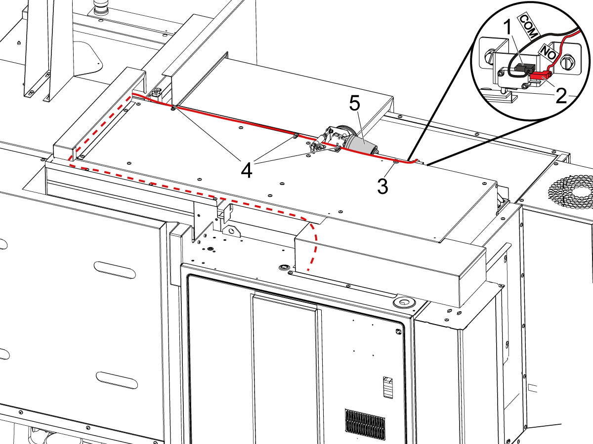
    Spojite prekidač POTPUNO OTVORANJE VRATA kako je označeno:

    • BLK <COM> na gornji terminal [1].
    • RED <NO> na srednji terminal [2].

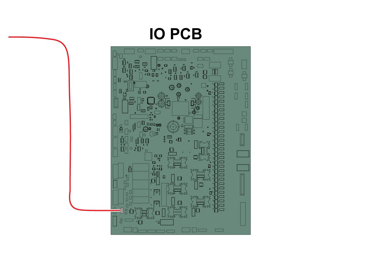
    Provedite kabel u upravljački ormarić kako je prikazano na slici.

    NAPOMENA: Obavezno ugradite priloženi magnetski držač [3] i stezaljke kabla [4] kako bi kabel bio podalje od motora s pomoćnim automatskim vratima [5].

    5

    Spojite drugi kraj kabela na SIO PCB P27 ulaz za otvaranje RRI vrata. 

    NAPOMENA: Provjerite je li stroj isključen.

    Ugradite poklopac automatskih vrata.

    6

    • Opružni potiskivač izrađen je s drškom koja odgovara držaču alata od 25 mm ili 1"
    • Ovaj alat mora preuzeti držač alata na revolveru
    • Ako je stroj ST-10/15 trebat će vam dva prazna držača alata kako bi se omogućilo dovoljno prostora za hvataljku
    • Programirajte sljedeće korake na početak bilo kojeg programa kako biste se uvjerili da je dio pravilno smješten u steznu glavu:
      • Pronađite opružni potiskivač ispred dijela
      • Pomičite Z-os da sabijete oprugu oko 0,50 inča ili 12,7 mm
      • Otvorite steznu glavu sa stankom od jedne sekunde
      • Zatvorite steznu glavu sa stankom od jedne sekunde
      • Vratite revolver u najsigurniji mogući položaj

    Napomena: Broj dijela za potiskivač opruge je: 

    • 30-12642 POTISKIVAČ OPRUGE APL.  Držač od 25 mm ili 1,0"" prodaje se zasebno.

    Cobot Installation

    1

    Provjerite jesu li kobot i njegova upravljačka kutija iz istog odgovarajućeg kompleta s odgovarajućim serijskim brojevima.

    Postoji bijela naljepnica s Haas serijskim brojem [1]. Pobrinite se da su isti na obje kutije.

    Postoji žuta okrugla naljepnica s identifikacijskim brojem [2]. Pobrinite se da su isti na obje kutije.

    2

    Izmjerite ove dimenzije od ruba stroja do bočne strane postolja.

     Preporučene  udaljenosti su sljedeće dimenzije. Položaj može varirati ovisno o primjeni korisnika. 

    Koristite dimenzije u sljedećim koracima kao referencu za kobote s prednjim i bočnim punjenjem. 

    Haas Kobot 10 preporučuje se koristiti u paru s Haas Cobot  postoljem. Ovo postolje je konfigurirano tako da bude dovoljno stabilno kada se koristi sukladno Haas definiranoj veličini obratka i ograničenjima težine. 

    3

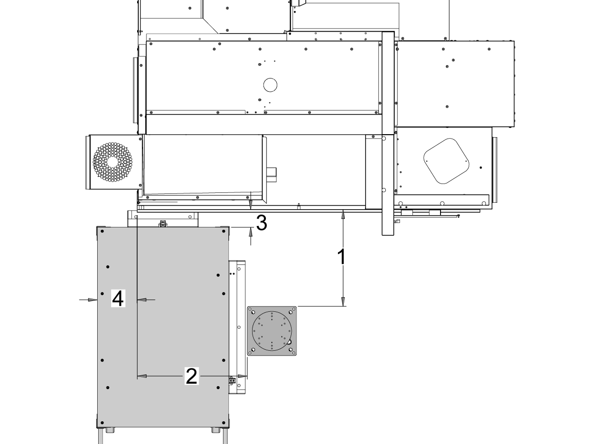
    ST-10 i ST-15 strojevi:

    Postavite postolje i stol za dijelove na sljedeću lokaciju u odnosu na stroj:

    Dimenzija Imperijalne (inči) Metrički (cm)
    Od prednje strane stroja do prednje strane postolja [1] 24,5 in 62,2 cm
    Od lijeve strane stroja do lijeve strane postolja[2] 26,25 in 66,7 cm
    Od prednje strane stroja do prednje strane stola za dijelove[4] 5,5 in 14 cm
    Od lijeve strane stroja do lijeve strane stola za dijelove [4] 9,75 in 24,7 cm

    4

    Updated

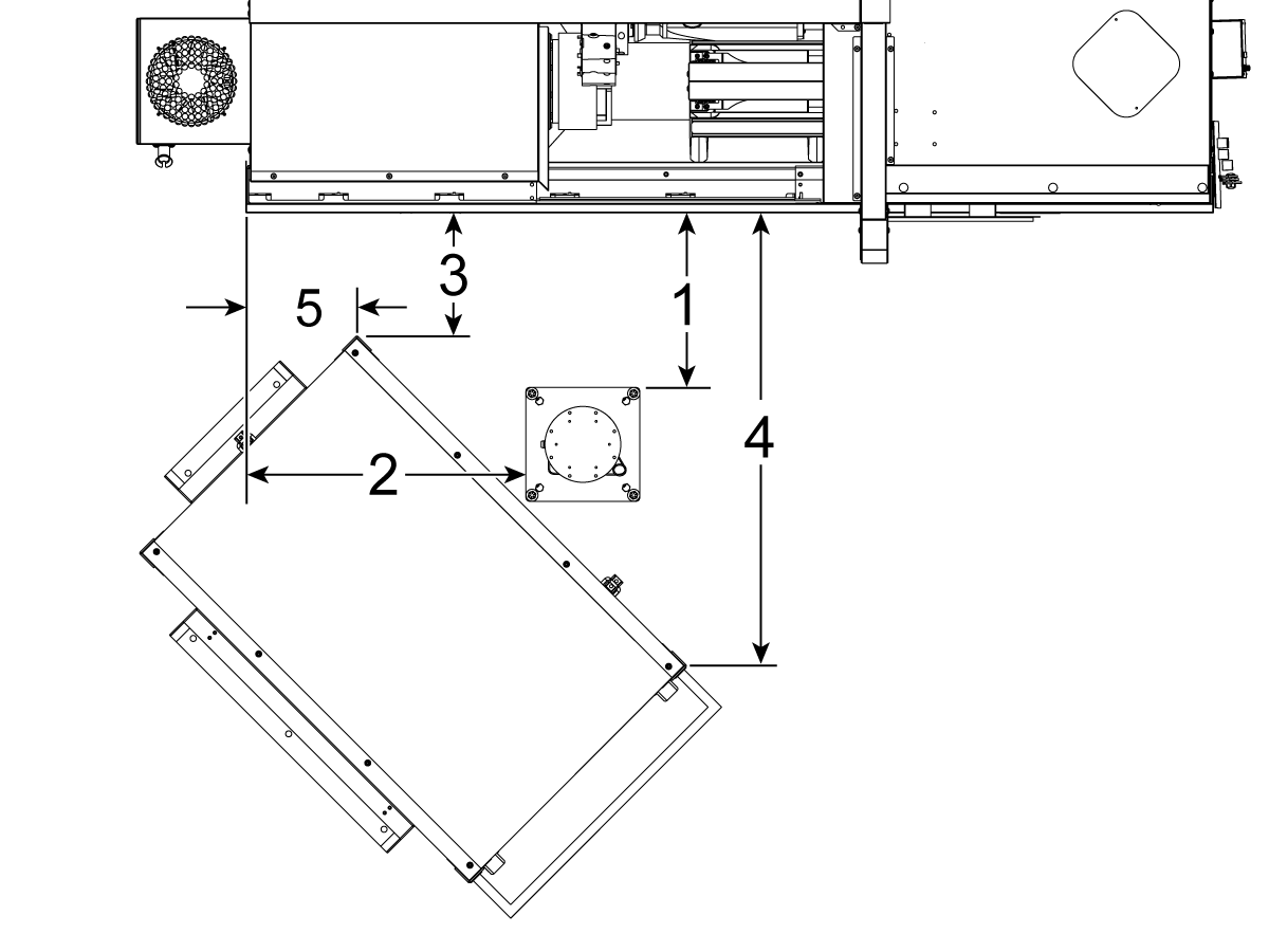
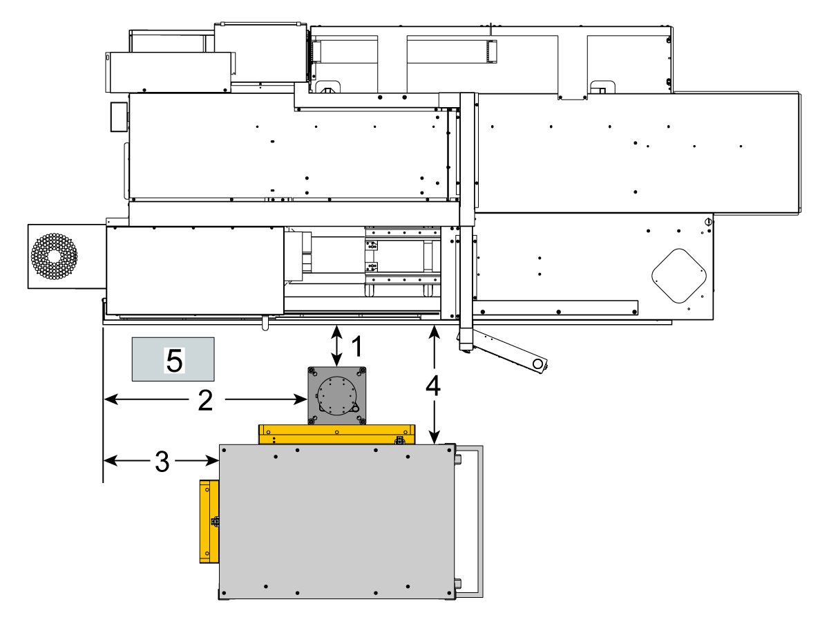
    ST-20 i ST-25 strojevi & DS-20Y/25Y:

    Postavite postolje i stol za dijelove na sljedeću lokaciju u odnosu na stroj:

    Dimenzija Imperijalne (inči) Metrički (cm)
    Od prednje strane stroja do prednje strane postolja [1] 19,5 in 49,5 cm
    Od lijeve strane stroja do lijeve strane postolja[2] 28,5 in 72,4 cm
    Prednja strana stroja do prednjeg lijevog kuta stola za dijelove [3] 14,5 in 36,8 cm
    Prednja strana stroja do prednjeg desnog kuta stola za dijelove [4] 71 in 180 cm
    Lijeva strana stroja do prednjeg lijevog kuta stola za dijelove [5] 10,75 in 27,3 cm

    5

    Strojevi

    ST-30/35 i DS-30Y:

    Postavite postolje, stol za dijelove i upravljačku kutiju kobota[5] na sljedeću lokaciju u odnosu na stroj:

    Dimenzija Imperijalne (inči) Metrički (cm)
    Od prednje strane stroja do prednje strane postolja [1] 8,5 in 21,6 cm
    Od lijeve strane stroja do lijeve strane postolja [2] 42,0 in 106,7 cm
    Od lijeve strane stroja do lijeve strane stola za dijelove [3] 23,5 in 59,7 cm
    Od prednje strane stroja do prednje strane stola za dijelove[4] 24,0 in 61,0 cm

    6

    Usidriti postolje u pod. Nivelirajte postolje pomoću libele. 

     NAPOMENA: Za podesivo postolje, postavite željenu visinu otpuštanjem uvrtnih vijaka [1], a zatim podešavanjem rascjepke [2]. Ponovno zategnite uvrtne vijke [1] prije instalacije robota. Postavite libelu na vrh postolja dok koristite (x4) šesterokutne vijke na bazi za postavljanje ravnine u X & Y ravnini.

    Postavite upravljačku kutiju kobota [3] izravno pored postolja kako biste osigurali dovoljno slobode za kabele. 

    7

    Izvadite robota iz transportne kutije. 

     NAPOMENA: Instalirajte adapter ploču između postolja i robota ako je potrebno. 

    Instalirajte kobot na vrh postolja.

     NAPOMENA: Pobrinite se da je konektor kabela kobota [1] kvadrat s prednjom stranom stroja. 

    VAŽNO: Kobot teži oko 40 lbs i trebao bi se podići uređajem koji može sigurno podići tu težinu.

    Uklonite hardver za podizanje robota nakon instalacije robota.

    8

    Unutar pakiranja kobota nalazi se mala vrećica [1] ispunjena rezervnim dijelovima, uključujući: 

    • osigurač
    • Vijci (x2)
    • Ključevi upravljačke kutije

    Postoji srednja vrećica [2] ispunjena dodatnim M12 priključkom. Ovaj kabel može se koristiti za konfiguriranje ulaza i izlaza za Krajnji I/O modul. 

    Postoji velika vrećica [3] ispunjena papirima i USB stikom na koji je preuzet softver za kobot.

    Pobrinite se da ove rezervne dijelove čuvate na sigurnom mjestu za buduću upotrebu. 

    Robot Electrical & Air - Installation

     DANGER: Working with the electrical services required for CNC machines is extremely hazardous and can result in serious injury or death.

    Before connecting line wires to the CNC:

    • Turn off all power to the machine at the source.
    • Perform a Lockout-Tagout (LOTO) procedure to ensure the power remains off during service.
    • Verify that power has been disconnected by using an AC voltage detector on all incoming lines.

    If you are uncertain about how to safely disconnect power or perform LOTO procedures:

    • Do not proceed.
    • Contact qualified personnel or obtain appropriate assistance before continuing.

    Failure to follow these precautions may result in electrical shock, equipment damage, or fatal injury.

     Danger: Before beginning any work inside the control cabinet, verify that the High Voltage indicator light on the 320V Power Supply / Vector Drive has been off for a minimum of five (5) minutes. This waiting period ensures that residual voltage has dissipated and reduces the risk of electric shock.

    Certain service procedures involve high-risk electrical components and may pose serious injury or fatality hazards. Technicians must not attempt any procedure unless they have a complete understanding of the steps involved and the associated risks.

    If there is any uncertainty regarding a procedure, contact your Haas Factory Outlet (HFO) to arrange for a qualified service technician.

    1

    Connect Interface Box to Haas Machine:

    The robot safety devices interface box 32-9018 has magnetic mounts to attach to the machine sheet metal. Mount the interface box [1] as shown in the picture.

    Route the interface electrical cables [2] along the enclosure with the magnetic mounts and zipties. Route the cable through the bottom of the electrical cabinet.

    NOTE: For information on upgrading the interface box to the Robot Safety Devices Interface Box, refer to the Robot Safety Devices Interface Box - Installation - AD0703. 

    2

    Connect Interface Box to Haas Control Cabinet:

    Connect cable 33-8562C E-STOP terminal block to TB-1B [1] and connect the Setup mode terminal block to TB-3B [1] on the SIO PCB.  

    Plug the user relay into K9 and K10 [2].

    Verify the jumper is installed on the SIO PCB at JP1.

    Connect the pigtail cable labeled P1 SIO to the SIO PCB at P1 [3]

    NOTE: If the machine has a Regen Vector Drive, unplug cable 33-0634 FILTER OV TO IOPCB P1 from P1 SIO and plug it into the connector FILTER OV FAULT on cable 33-8562C. If the machine does not have a Regen Vector Drive, do not plug anything into the connector FILTER OV FAULT.

    Connect the RJ-45 cable [4] to Ethernet to USB adapter [5] (33-0636).  Connect the USB connector end to the Maincon PCB J8 top port. Add a ferrite filter [6] to the USB adapter.

    Mount the 24VDC Power Supply [7] to the left side of the control cabinet and plug into connector labeled 24V PS on cable 33-8562C. Connect cable 33-1281 [8] to the 24VDC Power Supply [7] and plug into P3 on the PSUP PCB. 

    3

    For MM/SMM CM/CL machines Without XMR

    If P3 is occupied by a jumper connected from P3 [10] to P7 [9] on the PSUP PCB, a splitter cable is needed to allow the 24VDC power supply [7] to be connected to the 120VAC connectors on the PSUP. Connect the male connector of the splitter cable to P3 [10] and then connect the jumper from that cable to P7 [9] and also cable 33-1281 [8].

    Note: Make sure that the jumper cable is connected where the red lines up with the red from the splitter cable.

    4

    Inside the Cobot control box, install part of the robot signals cable (33-1272 or 33-1351).  To do so, remove the safety connector [1] from the Cobot control box in order to install the different colored wires into their respective location

    33-1272 / 33-1351 cables [2] going to safety connector:

    • Gray wire to top 24V
    • Red wire to bottom 24V
    • Green wire to EI0
    • Brown wire to EI1
    • Jumper [3] from SA0 to SA1
    • Jumper  [4] from SB0 to SB1

     NOTE: The rest of the wires from this cable are not used. Put some electrical tape on each wire lead and Ziptie the leftover unused wires. 

    5

    Important: After installing all the cables from the robot signal cable, make sure that the fuse [1] remains installed at all times to protect the Cobot control box.

    6

    Connect Cobot to the Interface Box:

    Connect the RJ45 ethernet cable [1] from the Cobot Control Box to the interface box. Add a ferrite filter [2] to the RJ-45 cable.

    Connect the robot signals cable [3] from the Cobot Control Box to the interface box. 

    Connect the 120 VAC Cobot Power Cable [4] to the external power source. 

    Connect the robot power cable [5] from the control box to the Cobot.

    Connect the teach pendant cable [6] from the control box to the teach pendant. 

    NOTE: For more information regarding interlock fence, area scanner or light curtain installation, refer to the Robot Safety Device section below.

    7

    Make sure the Remote Jog Handle is installed onto the machine.

    NOTE: For more information on the RJH-XL installation, refer to Remote Job Handle - Touch Large (RJH-XL) - Installation - AD0533. 

    8

    Steps 7 thru 10 are wiring and hose routing instructions for the pneumatic grippers. Refer to the grippers installation section lower on this page for the mechanical installation.

    Install the dual air solenoid assembly on to the side of the pedestal while giving the airlines enough slack. Make sure it's in a position where it will not be in the way. Route the airline [1] under the machine back towards the CALM cabinet as shown.

    9

    Inside the CALM cabinet, remove a plug from one of the CALM manifold ports and install the check valve [1] (58-1863) onto the port's fitting. Route the input airline [2] from the dual air solenoid assembly (from previous step) into the CALM cabinet and connect the airline to the check valve.

    Turn the machine air supply ON.

    10

    Make sure to power OFF the control box [1].

    Connect the solenoid cable from the dual air solenoid assembly [2] into the Digital Output on the Cobot control box [1]. Remove the connector from Cobot control box.

    11

    Connect the gripper solenoid power cable (33-1276 / 33-1341) to the Digital Output terminal inside the control box. Install the different colored wires into their respective location:

    • Black/white cable into 0V
    • Black cable into DO0
    • Orange/white cable into 0V
    • Orange cable into DO1
    • Red/white cable into 0V
    • Red cable into DO2
    • Brown/white cable into 0V
    • Brown cable into DO3

    Power ON the control box.

    Robot Safety Device

    VAŽNO: NEMOJTE KORISTITI ROBOTA DOK NISTE PRAVILNO KONFIGURIRALI I TESTIRALI RAD SIGURNOSNOG UREĐAJA.

    Svjetlosna zavjesa:

    Kobot paketi dolaze s odašiljačem i prijemnikom svjetlosne zavjese kao zadanim sigurnosnim uređajem. Slijedite postupak u nastavku za instalaciju svjetlosne zavjese: 

    Postavljanje svjetlosne zavjese

    NAPOMENA: Ako je naručen skener područja ili HC10 komplet spreman za ugradnju na stroj, bit će uključeni prijemnik i odašiljač svjetlosne zavjese od 1M. Oni dolaze sa svim kobotima.

    Robotska ograda:

    Ako je stroj došao opremljen opcijom ograde, sklop robotske ograde i zapor vrata treba ugraditi na stroj. Slijedite postupak za ugradnju u nastavku:

    Instalacija ograde robota

    Nakon instaliranja ograde, instalirajte ploču ograde između stroja i ograde robota.

    Skener područja:

    Ako je stroj došao opremljen opcijom skenera područja, skener područja treba ugraditi i konfigurirati za prostor. Slijedite postupak za ugradnju u nastavku: 

    Instalacija skenera područja

    First Power-UP

    1

    Power ON the Haas machine. 

    Power ON the Cobot by flipping the power switch [1].

    Power ON the Cobot teach pendant by pressing the circle [2]. 

    Make sure that E-STOP [3] on the Cobot teach pendant is released. 

    In order to change the language, click on the language drop down menu. Choose EN for English. To confirm this setting change, the Cobot teach pendant will have a popup asking to insert the username & password. 

    Enter "admin" for both the username and password. 

    2

    Note: The Cobot teach pendant will have a popup asking to insert the username & password. To sign into the teach pendant use these credentials:

    • Username = admin
    • Password = admin

    Go into Run mode. Press Enable. 

    Go into Jog mode [1].

    Move each joint to it's zero location with the Move Zero buttons [2]. 

    3

    Once the robot is in it's zero location, verify that the hash lines [1] align on either side of each joint on the Cobot. 

     IMPORTANT: If any joint hash lines [1] do not align, jog the specific joint accordingly until all the hash lines [1] do align. This position will be set in the next step as the new Cobot zero position.  

    Connect an ethernet cable [2] from the Cobot control box into a computer.

    On the computer, change the adapter setting to enable the ethernet port. 

    Note: See next steps for help on changing adapter settings.

    4

    To change the adapter settings, open the settings page [1] on the computer, then click on Network & Internet [2] which will bring up the network status page.

    Click on Change adapter options [3] then right click on Ethernet [4] and open up the properties window [5]. From there select the Internet Protocol Version 4 (TCP/IPv4) [6] option and click Ok. 


    5

    The ethernet settings will now be correct. Open a web browser window and type in the IP address of the Cobot[1]. 

    Note: This is the same process as connecting a laptop to an HRP-1/2/3. For more information on connecting to the Cobot via ethernet, refer to the video on the HRP-Troubleshooting page that is in the Connect & Jog Haas Robot section. 

    6

    Download HRTool through HBC. On the Service section of HBC, navigate to Utilities > Documents and Software > 01 Control Software > 01 Next Generation Control > 10 Cobot Software > HRTool.zip.

    Unzip the folder and navigate to HRToolsMaind.exe.

    Insert the Cobot IP address found under the Systems tab.  Click Set. 

    Go to the Config tab on HRTool.

    Click "get" to see the actual vs. theoretical encoder values. 

    Click "set" to set the theoretical to the actual encoder values. This step sets the Cobot's current position as it's new home position. 

    7

    Make sure that each joint's actual and theoretical encoder values match. 

    NOTE: If the valuyes do not match, press "Set" again. 

    8

    On the teach pendant, navigate to System [1] and then Update System. 

    Confirm the Cobot firmware [2] is either:

    • HR5.51H.16.beta.20231213.zip
    • HR6.4.9.tmp.20240919.zip

    NOTE: Firmware version HR6.4.9.tmp.20240919.zip is compatible with all size cobots.

    Refer to the Haas Cobot - Maintenance chapter for the firmware update procedure. 

    9

    Turn on the Haas CNC.

    Zero Return all Axes.

    Insert Service USB key.  Go into Service mode.

    Go to Parameters> Factory tab.  Change the following:

    • 1278 [1278:] Robot Ready E-Stop Enabled to TRUE
    • 2191 [694:] LIGHT CUTAIN TYPE to LC_TYPE_1
    • 2194 [:] Enable Front Door Fully Open Switch to TRUE

    Note: Machines with Software Version 100.20.000.1010 or higher will need to change the following parameter:

    • 2192 [:] Light Curtain Trigger Threshold to 0

    Press [SETTING].

    Set the Settings:

    • 372 Parts Loader Type to 3: Robot.
    • 376 Light Curtain Enabled to On


    10

    On the Haas pendant, press [CURRENT COMMANDS].

    Go to Devices>Robot>Jogging tab. Change the following:

    • Maximum Jogging Speed to 7.9 inch/sec

     Note: The jogging increments on the RJH are a percentage of this max speed value. In order to decrease the distance the robot travels of each jog wheel tick, you need to change your Maximum Jogging Speed to a lower value.

    Go to the Setup tab. Change the following:

    • Max Robot Speed to 118 in/sec (2000 mm/sec). 
    • Enter the Net Mass of the gripper. Refer to the layout drawings on our website (Single Gripper layout drawing OR Dual Gripper layout drawing) to get the correct value for this setting
    WARNING: Setting this value incorrectly can cause the Robot Arm to not move correctly. 
     
    • Number of Grippers to the number of grippers.
    • Raw Gripper Clamp Output to 1.
    • Raw Gripper Unclamp Output to 2.
    • Raw Gripper Clamp Delay to the clamp/unclamp duration in sec.
    • Raw Gripper Clamp Type to OD/ID.
    • Finish Gripper Clamp Output to 3.
    • Finish Gripper Unclamp Output to 4.
    • Finish Gripper Clamp Delay to the clamp/unclamp duration in sec.
    • Raw Gripper Clamp Type to OD/ID.

    Security Risk Level

    1

    IMPORTANT: Make sure to perform an appropriate risk-assessment and met all appropriate safety requirements. 

    2

    Based off the risk assessment, set the appropriate security risk level on the Cobot teach pendant. Navigate to Config > General Restrictions and tap of the desired security risk level [1] from 0 - 5.

    Use the  "admin" code in the safety verification to change the security level.

    NOTE: When the security risk level is lower, the robot will have a lower maximum speed, force, etc. When the security risk level is higher, the robot will have a higher maximum speed, force, etc. 

    This security risk level will calculate the maximum allowable force, speed, power, momentum, elbow speed and elbow force [2] that the Cobot will withstand before Alarm 9150.10017 Collison Stop Error is triggered. 

    IMPORTANT: The robot's programmed speed cannot be greater than the allowable speed from the security risk level. 

    NOTE: For more information regarding alarms, refer to the Haas Cobot - Troubleshooting Guide. 

    Activation

    1

    Download and load the configuration files by logging into the HAAS SERVICE PORTAL.

    Download the safety automation option front/side configuration files.

    Load the option configuration patch file to the control. Refer to the NEXT GENERATION CONTROL - CONFIGURATION FILE - DOWNLOAD/LOAD procedure.

    2

    Go to Parameters > Features > Robot to verify that the robot feature has appeared on the bottom.

    3

    Press [CURRENT COMMANDS].

    Go to Devices>Robot>Setup tab [1].

    Press [E-Stop].

    Press [F1] to connect the robot[2].

    The first time connecting a robot to a machine, the robot feature will need to be unlocked. This popup shows the machine's current software version, robot mac address and a generated code. Enter this information into HBC in order to receive the unlock code.

    4

    On HBC, go to the Service tab [1].

    On the left hand side of the screen, click on Activations [2], and then select Cobot Installation [3] to begin the process to the get the Cobot unlock code.

    The first step is to enter the Machine Serial Number [4] and the Cobot Serial Number [5] in the fields on HBC.

    Once you have entered the correct information, press Next [6] in the bottom right corner and continue through the steps until you receive the unlock code.

    Note: Make sure you are on the Cobot Installation tab [3] and not the Robot Installation tab. The Robot Installation is only used for the Haas Robot Packages. Using the Robot Installation for the Haas Cobots will result in an invalid unlock code.

    5

    Enter the Cobot's Haas Serial Number[1] and the unlock code to connect the robot to the machine. 

     Note: This step can only be completed by a HFO Service Technician.

     Note: The machine needs to be activated before the Cobot is activated. Follow the Machine Activation / Time Extension - NGC procedure.

    When the robot has connected with the machine, a yellow message saying Robot Activation Successful should appear at the bottom of the Haas screen.

    6

    Release the [E-STOP] and press RESET to clear the alarms. 

    Press the [HANDLE JOG] button. 

    Press the [CURRENT COMMANDS]  and go to Devices > Robot > Jogging tab.

     Note: The robot in setup mode can only be handle jogged while the F2 button the RJH is pressed. See Setup/Run mode section below.

    On the Remote Handle Jog Touch press the Joint button to go into the Joints Coordinates.

    Move the robot to an accessible location to install the grippers.

    Jog J6 to 0.0000 position. The location hole should be centered on top.

    Note: Press [E-STOP] before working on the robot.

    Gripper Installation

    1

    Turn off the machine air by turning the valve in the Air/Lube cabinet and pull the pressure relief valve to release the air in the system.

    2

    For the Dual Action Gripper:

    There are two versions of the dual-action grippers for this section, both of which have the same installation process.

    Jog the robot so that the location hole [1] is centered on top.

    Install the adapter plate [2] onto the end of the robot arm.

    Install the dual gripper assembly [3] onto the adapter plate [2].

    NOTE: Make sure to install Gripper 1 (which has the orange and purple zip ties) onto the Gripper 1 adapter plate section. 

    3

    For the Angled Single Action Gripper:

    Jog the robot so that the location hole [1] should be centered on top.

    Install the angle adapter plate [2] to the end of the robot arm.

    Install the single gripper assembly [3] onto the angle adapter plate [2]. 

    4

    To install the bar gripper fingers, remove the slug gripper plates from the gripper bodies.

    Install the Bar Gripper Bolt Plates [3] with (x8) SHCS M6 screws [4]. Torque to 10 ft-lbs.

    Install the Bar Gripper Fingers [2] with (x8) SHCS 1/4-20 [1]. Torque to 13 ft-lbs.

    5

    Configure the dual air solenoid assembly used for pneumatic grippers depending on single [1] or dual [2] gripper configuration. 

    For single grippers [1], connect the incoming air to the to the fitting [2] and keep the plug in the other end of the fitting [3] as shown in the image.

    For dual grippers [4], remove the plug in the fitting [3] and attach a small air hose to the second solenoid [5]. Then connect the incoming air hose to the fitting [2] so that both solenoids are receiving air.

    6

    For the Single Gripper:

    Route the (x2) air lines from the gripper to the same color coded fitting on the dual air solenoid assembly. 

    Secure the air lines by wrapping them in cable conduit. Use the velcro straps to attach the cable conduit to the Cobot. Make sure there is enough slack so that cables aren't strained when Cobot is fully extended.

    Insert the input air hose to the used solenoid's fitting [1]. 

    Make sure the plug is installed onto the unused solenoid's fitting [2]. 

    7

    For the Dual Gripper:

    Route the (x2) air lines from gripper #1 to the same color coded fitting on the dual air solenoid assembly. 

    Route the (x2) air lines from gripper #2 to the same color coded fitting on the dual air solenoid assembly. 

    Secure the air lines by wrapping them in cable conduit. Use the velcro straps to attach the cable conduit to the Cobot. Make sure there is enough slack so that cables aren't strained when Cobot is fully extended.

    Insert the short airline [1] connecting the first solenoid with the second. 

    Insert the input air hose to the fitting [2]. 

    Parts Table Assembly

    If the parts table option was ordered, follow the procedure below for assembly instructions:

    Haas Robot - Parts Table Assembly

    NOTE: If HC10 MACHINE READY KIT was purchased, there is no need to install the wheels if mounting the parts table directly into the wooden pallet. 

    Verification

    Test the E-stop:

    • Press each E-STOP button located on the Haas Pendant, RJH-XL, and Cobot Teach Pendant. Make sure the machine generates 107 EMERGENCY STOP alarm.  If the E-STOP button does not generate a 107 EMERGENCY STOP alarm verify the wiring. Load the latest configuration files to enable the RJH-XL.

    Test the Robot Safety Device:

    Make sure that there is an E-STOP or light curtain triggered icon on the Haas pendant when the robot safety device is triggered. 

    • Fence - Insert the key into the interlock, verify that the two red LED lights in the front of the interlock are OFF. Remove the key from the interlock, verify that the two red LED lights are ON. 
    • Area Scanner - Step inside the protective field, verify that the red LED lights up on the area scanner. Step outside the protective field, verify that the green LED lights up.
    • Light Curtain - Interfere the light curtain beams, verify that the light curtain triggered icon appears on the Haas pendant. Press [RESET]. Step outside of the light curtain beams, verify no icon appears on the Haas pendant. 

    NOTE: If the light curtain triggered icon does not show, verify wiring, alignment and factory setting: 2191 [694:] LIGHT CURTAIN TYPE is set to LC_TYPE_1.

    Test the Operation of the Grippers:

    • Verify that both grippers clamp and unclamp correctly.
    • Press the [CURRENT COMMANDS]  and go to Devices > Robot > Jogging tab.
    • Press [F2] to clamp/unclamp the Finish Gripper.
    • Press [F3] to clamp/unclamp the Raw Gripper.

    Test the Remote Jog Handle:

    • Undock the Remote Jog Handle
    • Press the [HANDLE JOG] button. 
    • Press the [CURRENT COMMANDS]  and go to Devices > Robot > Jogging tab.
    • On the Remote Handle Jog press the Joint button to go into the Joints Coordinates.
    • Move the robot to a safe location.

    IMPORTANT: If a yellow warning message appears saying "Please activate Light Curtain or Cell Safe" while trying to job the robot, verify the safety parameter was applied by re-uploading the configuration files from HBC. 

    Verify Safe / Run Mode Operation

    All Haas CNC machines are equipped with a key switch on the side of the control pendant to lock and unlock setup mode. The robot will have the following behaviors depending on what mode is selected. 

    • When the Haas control is in Run mode, mode 1, triggering the robot safety device stops all motion. This motion can not be started until the robot safety device is no longer triggered.
    • When the Haas control is in Set up mode, mode 2, speed limited motion such as jogging an axis of the robot can be performed in order to program a robot's path of motion, pick up position, set a robot's tool center point, (an offset), load and pick up parts from the spindle or part holder in the machine, etc. The programmed path will also be able to be run slowly to prove out the programmed path of the robot. The robot in setup mode can only be handle jogged while the F2 button the RJH is pressed.

    Haas Robot - Quick Start Guide

    Nakon što instalirate robot, postavite zadatak slijedeći sljedeći postupak.

    Haas robot - Kratki vodič za početak rada

    Disable the Robot

    Da biste onemogućili robotu da pokrene stroj u samostalnom načinu rada. Pritisnite [SETTING]. Promijenite sljedeće postavke:

    • 372 Tip sustava za dodavanje sirovca na 0: Ništa
    • 376 Omogućena svjetlosna zavjesa na isključeno


    5.3 DM/DT/MM/DC-1/UMC-350 Instalacija

    Recently Updated

    Haas Kobot 10 (HC10) - DM/DT/MM/DC-1/UMC-350 - Instalacija


    AD0716

    Revizija D - 11/2025

    Introduction

    Updated

    Ovaj postupak pokazat će vam kako ugraditi Haas 10KG kobot (HC10).

    Napomena: Radna ćelija koju je dizajnirao Haas i koja se sastoji od CNC stroja te robot procijenjeni su za usklađenost s CE zahtjevima. Promjene ili varijacije dizajna ćelija tvrtke Haas trebaju se procijeniti u pogledu usklađenosti s primjenjivim standardima i odgovornost su korisnika/integratora.

    Zahtjevi za stroj:

      Verzija
    • 100.24.000.1001 ili novija
    • Verzija
    • HR5.51H.16.beta.20231213.zip ili verzija HR6.4.9.tmp20240919.zip
    • DT/DM/MM/SMM/DC-1/UMC-350 Proizvedeno nakon datuma: (pogledajte zahtjeve stroja u oba postupka)
      • Haas automatska vrata
      • Haas Automatski prozor
        Napomena:MM/SMM, DM-3, DT-3 i DC-1 su dostupni samo za opciju bočnog umetanja(93-1001053).
      • Napomena: Mini glodalica/SUPER mini glodalica strojevi bez transformatora zahtijevat će razdjelnik kabela koji treba naručiti za kobote koji se instaliraju na terenu. Razdjelnik kabela može se naručiti kao 93-5067.

    • 34-349xB I/O ploča ili novija
    • 93-1000610 DALJINSKA RUČICA ZA RUČNO POMICANJE OSI STROJA S DODIRNIM LCD EKRANOM (RJH-XL) DALJINSKA RUČICA ZA RUČNO POMICANJE OSI STROJA - XL

    Potreban alat:

    • Mali ravni odvijač

    Fixing / Anchoring Requirements

    • The Haas 10KG Cobot (HC10) is configured and sold by Haas with a pedestal/table that is sufficiently stable when used according to Haas defined part size and weight limits. 
    IMPORTANT:  For more information directly on the Hans Cobot, refer to the Hans Robot Operation Manual for Elfin Software.

    There are 3 scenarios in which the cobot option can be installed on a Haas machine:

    1. Cobot option was ordered at the same time as the machine. Both the cobot and the machine are being installed together.
    2. Cobot option is ordered so that it can be installed on a previously installed machine.
    3. Cobot option was previously installed on a machine, but will now be moved to a different Haas machine.

    In scenarios 2 and 3, additional parts will need to be ordered under the Serial Number of the Haas machine. See the tables below for what parts are needed in the different scenarios.

    Scenario 1 - Cobot and Machine are ordered and installed together

    Component Part Number Description
    NO ADDITIONAL PARTS NEED TO BE ORDERED WHEN COBOT AND MACHINE ARE ORDERED TOGETHER

    Scenario 2 - Cobot being field installed on existing Haas Machine

    Component Part Number Description
    CHECK TO SEE IF HAAS MACHINE ALREADY HAS THESE FEATURES & PARAMETERS BEFORE ORDERING
    Robot Feature Unlock Parameter 93-1001031 Kit activates the robot feature on the Haas machine. To check if you need this kit, go to the Features tab on the Haas Control and check if the Robot option is highlighted. This kit does not include any physical parts.
    Load Type Safety Parameters 93-1000997 Front Automation Safety Parameters - Kit is needed when the cobot will be loading parts through the front door of the Haas machine. This kit does not include any physical parts and the autodoor option would need to be purchased and installed separately.
    OR  
    93-1000996 Side Automation Safetly Parameters - Kit is needed when the cobot will be loading parts through the side window of the Haas machine. This kit does not include any physical parts and the autowindow option would need to be purchased and installed separately.

    Scenario 3 - Cobot is being transferred from one machine to a different Haas Machine

    Component Part Number Description
    Cobot Integration Kit See Integration Kit Compatibility Chart Kit is needed to install parts on the Haas machine to interface with the cobot. This includes the interface box, door switches, etc... as well as the Robot Unlock Feature parameter. This kit only needs to be purchased when transferring a cobot to a new Haas machine since these parts are normally included when a cobot is ordered. 
    Load Type Safety Parameters 93-1000997 Front Automation Safety Parameters - Kit is needed when the cobot will be loading parts through the front door of the Haas machine. This kit does not include any physical parts and the autodoor option would need to be purchased and installed separately.
    OR  
    93-1000996 Side Automation Safetly Parameters - Kit is needed when the cobot will be loading parts through the side window of the Haas machine. This kit does not include any physical parts and the autowindow option would need to be purchased and installed separately.
    Safety Device 08-1899 Multi-Sided Light Curtain Kit - Kit is needed if the safety device is NOT going to be transferred from the first machine and the second Haas machine needs it's own safety device. This kit makes a 4-sided protective barrier.
    OR  
    08-1948 5-Sided Light Curtain Kit - Kit is needed when the safety device is NOT going to be transferred from the first machine machine and the second Haas machine needs it's own safety device. This kit makes a 5-sided protective barrier.
    OR  
    08-1987 Laser Area Scanner Kit - Kit is needed when the safety device is NOT going to be transferred from the first machine machine and the second Haas machine needs it's own safety device. This area scanner has a sensing distance of 4meters.

    Machine Setup

    1

    Robot za umetanje sprijeda:

    Pričvrstite vodilicu za bušenje [1] za senzor blizine [2] na vrh kućišta.

    Izbušite i navijte 2x 10-32 rupe kroz bočnu stranu kućišta.

    • Veličina bušenja: # 21 ili 5/32"
    • Urežite navoje 10-32 NF

    Uklonite vodilicu za bušenje [1]. 

    Ugradite prekidač za blizinu otvorenih vrata [2] na ove otvore na bočnoj strani kućišta.

    Uključite senzor blizine da biste pronašli željenu zastavicu puta [3] na vratima. Nakon što je zastavica puta [3] na dobrom mjestu za aktiviranje senzora blizine, označite mjesto rupe. 

    Instalirajte zastavicu puta [3] samonareznim vijcima na bočnu stranu vrata. 

    Provedite kabel u upravljački ormarić kako je prikazano na slici.

    Spojite kabel blizinskog prekidača na SIO PCB P27. 

    2

    Robot za bočno punjenje:

    Uklonite poklopac [1] i njegov okov [2] kako biste izložili zračni cilindar [4] automatskog prozora. Podignite zračni cilindar [4] tako da nosači [3] i zračni cilindar budu pričvršćeni kako je prikazano.

    Spojite priložena siva i žuta crijeva za zrak na zračni cilindar automatskog prozora - priključci na zračnom cilindru imat će sive i žute vezice koje pokazuju gdje se svako crijevo spaja.

    Ugradite poklopac [2] preko zračnog cilindra automatskog prozora.

    3

    • Opružni potiskivač izrađen je s drškom koja odgovara držaču alata od 25 mm ili 1"
    • Ovaj alat mora preuzeti držač alata u karuselu alata.
    • Programirajte sljedeće korake na početak bilo kojeg  programa kako biste se uvjerili da je dio pravilno smješten u steznu glavu:
      • Pronađite opružni potiskivač iznad dijela
      • Pomičite Z-os da sabijete oprugu oko 0,50 inča ili 12,7 mm
      • Otvorite škripac sa stankom od jedne sekunde
      • Zatvorite škripac sa stankom od jedne sekunde

    Napomena: Broj dijela za potiskivač opruge je: 

    • 30-12642 POTISKIVAČ OPRUGE APL.  Držač od 25 mm ili 1,0"" prodaje se zasebno.

    Cobot Installation

    1

    Provjerite jesu li kobot i njegova upravljačka kutija iz istog odgovarajućeg kompleta s odgovarajućim serijskim brojevima.

    Postoji bijela naljepnica s Haas serijskim brojem [1]. Pobrinite se da su isti na obje kutije.

    Postoji žuta okrugla naljepnica s identifikacijskim brojem [2]. Pobrinite se da su isti na obje kutije.

    2

    Izmjerite ove dimenzije od ruba stroja do bočne strane postolja.

     Preporučene  udaljenosti su sljedeće dimenzije. Položaj se može razlikovati ovisno o aplikaciji korisnika. Pogledajte sljedeće korake za pozicioniranje kobota i stola za dijelove za kobote s prednjim ili bočnim umetanjem.

    Haas Kobot 10 preporučuje se koristiti u paru s Haas Cobot  postoljem. Ovo postolje je konfigurirano tako da bude dovoljno stabilno kada se koristi sukladno Haas definiranoj veličini obratka i ograničenjima težine. 

    3

    Prednje punjenje:

    Postavite postolje i stol za dijelove na sljedeću lokaciju u odnosu na stroj:

    Dimenzija Imperijalne (inči) Metrički (cm)
    Od prednje strane stroja do prednje strane postolja [1] 13 in. 33 cm.
    Od lijeve strane stroja do lijeve strane postolja[2] 24 in. 61 cm.
    Prednja strana stroja do prednjeg lijevog kuta stola za dijelove [3] 8 in. 20,3 cm.
    Prednja strana stroja do prednjeg desnog kuta stola za dijelove [4] 42,25 in. 107 cm.
    Lijeva strana stroja do prednjeg lijevog kuta stola za dijelove [5] 6,25 in. 15,9 cm.

    4

    Bočno umetanje:

    Postavite postolje i stol za dijelove na sljedeću lokaciju u odnosu na stroj:

    Dimenzija Imperijalne (inči) Metrički (cm)
    Od prednje strane stroja do lijeve strane postolja [1] 21 in. 53,4 cm.
    Desna strana stroja do prednje strane postolja [2] 13 in. 33 cm.
    Od prednje strane stroja do lijeve strane stola za dijelove[3] 3 in. 7,6 cm.
    Desna strana stroja do prednje strane stola za dijelove [4] 27 in. 68,6 cm.

    5

    Usidriti postolje u pod. Nivelirajte postolje pomoću libele. 

    Postavite željenu visinu otpuštanjem uvrtnih vijaka [1], a zatim podešavanjem rascjepke [2]. Ponovno zategnite uvrtne vijke [1] prije instalacije robota. Postavite libelu na vrh postolja dok koristite (x4) šesterokutne vijke na bazi za postavljanje ravnine u X & Y ravnini.

    Postavite upravljačku kutiju kobota [3] izravno pored postolja kako biste osigurali dovoljno slobode za kabele. 

    Napomena: Rasporedi u prethodnim koracima imaju visinu postolja od 24 inča (61 cm).

    6

    Izvadite robota iz transportne kutije. 

     NAPOMENA: Instalirajte adapter ploču između postolja i robota ako je potrebno. 

    Instalirajte kobot na vrh postolja.

     NAPOMENA: Pobrinite se da je konektor kabela kobota [1] kvadrat s prednjom stranom stroja. 

    VAŽNO: Kobot teži oko 40 lbs i trebao bi se podići uređajem koji može sigurno podići tu težinu.

    Uklonite hardver za podizanje robota nakon instalacije robota.

    7

    Unutar pakiranja kobota nalazi se mala vrećica [1] ispunjena rezervnim dijelovima, uključujući: 

    • osigurač
    • Vijci (x2)
    • Ključevi upravljačke kutije

    Postoji srednja vrećica [2] ispunjena dodatnim M12 priključkom. Ovaj kabel može se koristiti za konfiguriranje ulaza i izlaza za Krajnji I/O modul. 

    Postoji velika vrećica [3] ispunjena papirima i USB stikom na koji je preuzet softver za kobot.

    Pobrinite se da ove rezervne dijelove čuvate na sigurnom mjestu za buduću upotrebu. 

    Robot Electrical & Air - Installation

    1

    Connect Interface Box to Haas Machine:

    The robot safety devices interface box 32-9018 has magnetic mounts to attach to the machine sheet metal. Mount the interface box [1] as shown in the picture.

    Route the interface electrical cables [2] along the enclosure with the magnetic mounts and zipties. Route the cable through the bottom of the electrical cabinet.

    NOTE: For information on upgrading the interface box to the Robot Safety Devices Interface Box, refer to the Robot Safety Devices Interface Box - Installation - AD0703. 

    2

    Connect Interface Box to Haas Control Cabinet:

    Connect cable 33-8562C E-STOP terminal block to TB-1B [1] and connect the Setup mode terminal block to TB-3B [1] on the SIO PCB.  

    Plug the user relay into K9 and K10 [2].

    Verify the jumper is installed on the SIO PCB at JP1.

    Connect the pigtail cable labeled P1 SIO to the SIO PCB at P1 [3]

    NOTE: If the machine has a Regen Vector Drive, unplug cable 33-0634 FILTER OV TO IOPCB P1 from P1 SIO and plug it into the connector FILTER OV FAULT on cable 33-8562C. If the machine does not have a Regen Vector Drive, do not plug anything into the connector FILTER OV FAULT.

    Connect the RJ-45 cable [4] to Ethernet to USB adapter [5] (33-0636).  Connect the USB connector end to the Maincon PCB J8 top port. Add a ferrite filter [6] to the USB adapter.

    Mount the 24VDC Power Supply [7] to the left side of the control cabinet and plug into connector labeled 24V PS on cable 33-8562C. Connect cable 33-1281 [8] to the 24VDC Power Supply [7] and plug into P3 on the PSUP PCB. 

    3

    For MM/SMM CM/CL machines Without XMR

    If P3 is occupied by a jumper connected from P3 [10] to P7 [9] on the PSUP PCB, a splitter cable is needed to allow the 24VDC power supply [7] to be connected to the 120VAC connectors on the PSUP. Connect the male connector of the splitter cable to P3 [10] and then connect the jumper from that cable to P7 [9] and also cable 33-1281 [8].

    Note: Make sure that the jumper cable is connected where the red lines up with the red from the splitter cable.

    4

    Inside the Cobot control box, install part of the robot signals cable (33-1272 or 33-1351).  To do so, remove the safety connector [1] from the Cobot control box in order to install the different colored wires into their respective location

    33-1272 / 33-1351 cables [2] going to safety connector:

    • Gray wire to top 24V
    • Red wire to bottom 24V
    • Green wire to EI0
    • Brown wire to EI1
    • Jumper [3] from SA0 to SA1
    • Jumper  [4] from SB0 to SB1

     NOTE: The rest of the wires from this cable are not used. Put some electrical tape on each wire lead and Ziptie the leftover unused wires. 

    5

    Important: After installing all the cables from the robot signal cable, make sure that the fuse [1] remains installed at all times to protect the Cobot control box.

    6

    Connect Cobot to the Interface Box:

    Connect the RJ45 ethernet cable [1] from the Cobot Control Box to the interface box. Add a ferrite filter [2] to the RJ-45 cable.

    Connect the robot signals cable [3] from the Cobot Control Box to the interface box. 

    Connect the 120 VAC Cobot Power Cable [4] to the external power source. 

    Connect the robot power cable [5] from the control box to the Cobot.

    Connect the teach pendant cable [6] from the control box to the teach pendant. 

    NOTE: For more information regarding interlock fence, area scanner or light curtain installation, refer to the Robot Safety Device section below.

    7

    Make sure the Remote Jog Handle is installed onto the machine.

    NOTE: For more information on the RJH-XL installation, refer to Remote Job Handle - Touch Large (RJH-XL) - Installation - AD0533. 

    8

    Steps 7 thru 10 are wiring and hose routing instructions for the pneumatic grippers. Refer to the grippers installation section lower on this page for the mechanical installation.

    Install the dual air solenoid assembly on to the side of the pedestal while giving the airlines enough slack. Make sure it's in a position where it will not be in the way. Route the airline [1] under the machine back towards the CALM cabinet as shown.

    9

    Inside the CALM cabinet, remove a plug from one of the CALM manifold ports and install the check valve [1] (58-1863) onto the port's fitting. Route the input airline [2] from the dual air solenoid assembly (from previous step) into the CALM cabinet and connect the airline to the check valve.

    Turn the machine air supply ON.

    10

    Make sure to power OFF the control box [1].

    Connect the solenoid cable from the dual air solenoid assembly [2] into the Digital Output on the Cobot control box [1]. Remove the connector from Cobot control box.

    11

    Connect the gripper solenoid power cable (33-1276 / 33-1341) to the Digital Output terminal inside the control box. Install the different colored wires into their respective location:

    • Black/white cable into 0V
    • Black cable into DO0
    • Orange/white cable into 0V
    • Orange cable into DO1
    • Red/white cable into 0V
    • Red cable into DO2
    • Brown/white cable into 0V
    • Brown cable into DO3

    Power ON the control box.

    Robot Safety Device

    VAŽNO: NEMOJTE KORISTITI ROBOTA DOK NISTE PRAVILNO KONFIGURIRALI I TESTIRALI RAD SIGURNOSNOG UREĐAJA.

    Svjetlosna zavjesa:

    Kobot paketi dolaze s odašiljačem i prijemnikom svjetlosne zavjese kao zadanim sigurnosnim uređajem. Slijedite postupak u nastavku za instalaciju svjetlosne zavjese: 

    Postavljanje svjetlosne zavjese

    NAPOMENA: Ako je naručen skener područja ili HC10 komplet spreman za ugradnju na stroj, bit će uključeni prijemnik i odašiljač svjetlosne zavjese od 1M. Oni dolaze sa svim kobotima.

    Robotska ograda:

    Ako je stroj došao opremljen opcijom ograde, sklop robotske ograde i zapor vrata treba ugraditi na stroj. Slijedite postupak za ugradnju u nastavku:

    Instalacija ograde robota

    Nakon instalacije ograde, instalirajte ploču ograde između stroja i ograde robota, počevši s pločom koja se pričvršćuje na vrh stroja.

    Napomena: Metalne zidne ploče koje povezuju ogradu s kućištem stroja moraju se instalirati koristeći isporučene samonarezne vijke i neće se poravnati s rupama.

    Skener područja: 

    Ako je stroj došao opremljen opcijom skenera područja, skener područja treba ugraditi i konfigurirati za prostor. Slijedite postupak za ugradnju u nastavku: 

    Instalacija skenera područja

    First Power-UP

    1

    Uključite Haas stroj. 

    Uključite upravljačku kutiju kobota okretanjem prekidača za napajanje [1].

    Uključite privjesak (ručno kolo) za obuku kobota pritiskom na krug [2]. 

    Pobrinite se da je E-STOP [3] na privjesku (ručnom kolu) za obuku kobota otpušten. 

    Da biste promijenili jezik, kliknite na padajući izbornik jezika. Odaberite HR za hrvatski. Za potvrdu ove promjene postavki, privjesak (ručno kolo) za obuku Kobota imat će skočni prozor koji traži unos korisničkog imena I lozinke. 

    Unesite "admin" za korisničko ime i lozinku. 

    2

    Napomena: privjesak (ručno kolo) za obuku Kobota imat će skočni prozor koji traži unos korisničkog imena I lozinke. Za prijavu na privjesak (ručno kolo) za obuku koristite ove vjerodajnice:

    • Korisničko ime = admin
    • Lozinka = admin

    Uđite u način rada Pokreni. Pritisnite Omogući. 

    Uđite u način rada Ručno pomicanje [1].

    Pomaknite svaki zglob na nultu lokaciju pomoću gumba Pomakni na Nulu [2]. 

    3

    Kada je robot u nultoj lokaciji, provjerite jesu li hash linije [1] poravnate s obje strane svakog zgloba na kobotu. 

     Važno: Ako bilo koje hash crte zglobova [1] nisu poravnate, ručno pomaknite određeni zglob dok se sve hash crte [1] ne poravnaju. Ova pozicija bit će postavljena u sljedećem koraku kao nova nulta pozicija Kobota.  

    Spojite ethernet kabel [2] iz upravljačke kutije kobota u računalo.

    Na računalu promijenite postavku adaptera da biste omogućili priključak za ethernet. 

    Napomena: Pogledajte sljedeće korake za pomoć pri promjeni postavki adaptera.

    4

    Za promjenu postavki adaptera otvorite stranicu postavki [1] na računalu, a zatim kliknite na Mreža & internet [2] što će otvoriti stranicu statusa mreže.

    Kliknite na Opcije Promijeni prilagodnika [3], a zatim kliknite desno na Ethernet [4] i otvorite prozor svojstva [5]. Od tamo odaberite opciju Internetski protokol Verzija 4 (TCP/IPv4) [6] i kliknite Ok. 


    5

    Postavke etherneta sada će biti točne. Otvorite web preglednik i upišite IP adresu Kobota [1]. 

    Napomena: To je isti postupak kao spajanje prijenosnog računala na HRP-1/2/3. Za više informacija o povezivanju s Kobotom putem etherneta, pogledajte video na stranici HRP-Rješavanje problema koja se nalazi u odjeljku Povezivanje I ručno pomicanje Haas robota. 

    6

    Preuzmite HRTool kroz HBC. U odjeljku Servisa HBC-a, idite na Alati > Dokumenti i Softver > 01 Kontrolni Softver > 01 Upravljački softver Next Generation > 10 kobot Softver > HRTool.zip.

    Raspakirajte mapu i navigirajte do HRToolsMaind.exe.

    Umetnite IP adresu kobota koja se nalazi pod karticom Sustavi.  Kliknite Postavi. 

    Idite na karticu Konfiguracija u HRToolu.

    Kliknite "get" da biste vidjeli stvarne nasuprot teoretskim vrijednostima enkodera. 

    Kliknite "set" da postavite teorijske vrijednosti na stvarne vrijednosti enkodera. Ovaj korak postavlja trenutnu poziciju Kobota kao njegovu novu početnu poziciju. 

    7

    Provjerite podudaraju li se stvarne i teorijske vrijednosti enkodera za svaki zglob. 

    NAPOMENA: Ako se vrijednosti ne podudaraju, ponovno pritisnite "Set". 

    8

    Na privjesku (ručnom kolu) za obuku, navigirajte do Sustav [1] i zatim Ažuriraj Sustav. 

    Potvrdite da je firmver kobota [2] ili:

    • HR5.51H.16.beta.20231213.zip
    • HR6.4.9.tmp.20240919.zip

    NAPOMENA: Verzija firmvera HR6.4.9.tmp.20240919.zip je kompatibilna s kobotima svih veličina.

    Pogledajte poglavlje Haas kobot - Održavanje za postupak ažuriranja firmvera. 

    9

    Uključite Haas CNC.

    Sve osi vratite u referentnu točku.

    Umetnite servisni USB ključ.  Prijeđite na servisni način rada.

    Idite na karticu Parametri> Tvornički.  Promijenite sljedeće:

    • 1278 [1278:] Omogućeno zaustavljanje u nuždi za robota na TRUE
    • 2191 [694:] VRSTA SVJETLOSNE ZAVJESE na LC_TYPE_1
    • 2194 [:] Omogući Prednja vrata potpuno otvorena prekidač na ISTINITO

    Bilješka: Strojevi s verzijom softvera 100.20.000.1010 ili novijom morat će promijeniti sljedeći parametar:

    • 2192 [:] Light Curtain Trigger Threshold na 0

    Pritisnite [SETTING].

    Postavite postavke:

    • 372 - Vrsta sustava za dodavanje sirovca na 3: Robot.
    • 376 - Omogućena svjetlosna zavjesa na On


    10

    Na Haas privjesak (ručno kolo) pritisnite [CURRENT COMMANDS].

    Idite na karticu Uređaji>Robot>Ručno pomicanje . Promijenite sljedeće:

    • Maksimalna brzina ručnog pomicanja do 7,9  inča/sek.

     Napomena: Inkrementi ručnog pomicanja na RJH-u su postotak ove maksimalne vrijednosti brzine. Da biste smanjili udaljenost koju robot prelazi sa svakim pomakom kotačića za ručno pomicanje, trebate promijeniti svoju Maksimalnu brzinu ručnog pomicanja na nižu vrijednost.

    Idite na karticuPostavljanje . Promijenite sljedeće:

    • Maksimalna brzina robota do 118 in/s (2000 mm/s). 
    • Unesite neto masu hvataljke. Pogledajte nacrte rasporeda na našoj web stranici (Nacrt rasporeda jednostruke hvataljke ILI Nacrt rasporeda dvoostruke hvataljke) za točnu vrijednost ove postavke.

    UPOZORENJE: Postavljanje ove vrijednosti netočno može uzrokovati da se robotska ruka ne kreće ispravno. 

     
    • Broj hvataljki na broj hvataljki.
    • Izlaz stezanja sirove čeljusti na 1.
    • Izlaz hvataljke za otpuštanje sirovca na 2.
    • Odgoda stezanja sirove čeljusti na trajanje stezanja / otpuštanja u sec.
    • Vrsta stezanja sirove čeljusti na OD/ID.
    • Izlaz hvataljke za stezanje gotovog komada na 3.
    • Izlaz hvataljke za otpuštanje gotovog komada na 4.
    • Odgoda stezanja završnog prihvata na trajanje stezanja/otpuštanja u sek.
    • Vrsta stezanja sirove čeljusti na OD/ID.

    Security Risk Level

    1

    IMPORTANT: Make sure to perform an appropriate risk-assessment and met all appropriate safety requirements. 

    2

    Based off the risk assessment, set the appropriate security risk level on the Cobot teach pendant. Navigate to Config > General Restrictions and tap of the desired security risk level [1] from 0 - 5.

    Use the  "admin" code in the safety verification to change the security level.

    NOTE: When the security risk level is lower, the robot will have a lower maximum speed, force, etc. When the security risk level is higher, the robot will have a higher maximum speed, force, etc. 

    This security risk level will calculate the maximum allowable force, speed, power, momentum, elbow speed and elbow force [2] that the Cobot will withstand before Alarm 9150.10017 Collison Stop Error is triggered. 

    IMPORTANT: The robot's programmed speed cannot be greater than the allowable speed from the security risk level. 

    NOTE: For more information regarding alarms, refer to the Haas Cobot - Troubleshooting Guide. 

    Activation

    1

    Download and load the configuration files by logging into the HAAS SERVICE PORTAL.

    Download the safety automation option front/side configuration files.

    Load the option configuration patch file to the control. Refer to the NEXT GENERATION CONTROL - CONFIGURATION FILE - DOWNLOAD/LOAD procedure.

    2

    Go to Parameters > Features > Robot to verify that the robot feature has appeared on the bottom.

    3

    Press [CURRENT COMMANDS].

    Go to Devices>Robot>Setup tab [1].

    Press [E-Stop].

    Press [F1] to connect the robot[2].

    The first time connecting a robot to a machine, the robot feature will need to be unlocked. This popup shows the machine's current software version, robot mac address and a generated code. Enter this information into HBC in order to receive the unlock code.

    4

    On HBC, go to the Service tab [1].

    On the left hand side of the screen, click on Activations [2], and then select Cobot Installation [3] to begin the process to the get the Cobot unlock code.

    The first step is to enter the Machine Serial Number [4] and the Cobot Serial Number [5] in the fields on HBC.

    Once you have entered the correct information, press Next [6] in the bottom right corner and continue through the steps until you receive the unlock code.

    Note: Make sure you are on the Cobot Installation tab [3] and not the Robot Installation tab. The Robot Installation is only used for the Haas Robot Packages. Using the Robot Installation for the Haas Cobots will result in an invalid unlock code.

    5

    Enter the Cobot's Haas Serial Number[1] and the unlock code to connect the robot to the machine. 

     Note: This step can only be completed by a HFO Service Technician.

     Note: The machine needs to be activated before the Cobot is activated. Follow the Machine Activation / Time Extension - NGC procedure.

    When the robot has connected with the machine, a yellow message saying Robot Activation Successful should appear at the bottom of the Haas screen.

    6

    Release the [E-STOP] and press RESET to clear the alarms. 

    Press the [HANDLE JOG] button. 

    Press the [CURRENT COMMANDS]  and go to Devices > Robot > Jogging tab.

     Note: The robot in setup mode can only be handle jogged while the F2 button the RJH is pressed. See Setup/Run mode section below.

    On the Remote Handle Jog Touch press the Joint button to go into the Joints Coordinates.

    Move the robot to an accessible location to install the grippers.

    Jog J6 to 0.0000 position. The location hole should be centered on top.

    Note: Press [E-STOP] before working on the robot.

    Gripper Installation

    1

    Turn off the machine air by turning the valve in the Air/Lube cabinet and pull the pressure relief valve to release the air in the system.

    2

    For the Dual Action Gripper:

    There are two versions of the dual-action grippers for this section, both of which have the same installation process.

    Jog the robot so that the location hole [1] is centered on top.

    Install the adapter plate [2] onto the end of the robot arm.

    Install the dual gripper assembly [3] onto the adapter plate [2].

    NOTE: Make sure to install Gripper 1 (which has the orange and purple zip ties) onto the Gripper 1 adapter plate section. 

    3

    For the Angled Single Action Gripper:

    Jog the robot so that the location hole [1] should be centered on top.

    Install the angle adapter plate [2] to the end of the robot arm.

    Install the single gripper assembly [3] onto the angle adapter plate [2]. 

    4

    To install the bar gripper fingers, remove the slug gripper plates from the gripper bodies.

    Install the Bar Gripper Bolt Plates [3] with (x8) SHCS M6 screws [4]. Torque to 10 ft-lbs.

    Install the Bar Gripper Fingers [2] with (x8) SHCS 1/4-20 [1]. Torque to 13 ft-lbs.

    5

    Configure the dual air solenoid assembly used for pneumatic grippers depending on single [1] or dual [2] gripper configuration. 

    For single grippers [1], connect the incoming air to the to the fitting [2] and keep the plug in the other end of the fitting [3] as shown in the image.

    For dual grippers [4], remove the plug in the fitting [3] and attach a small air hose to the second solenoid [5]. Then connect the incoming air hose to the fitting [2] so that both solenoids are receiving air.

    6

    For the Single Gripper:

    Route the (x2) air lines from the gripper to the same color coded fitting on the dual air solenoid assembly. 

    Secure the air lines by wrapping them in cable conduit. Use the velcro straps to attach the cable conduit to the Cobot. Make sure there is enough slack so that cables aren't strained when Cobot is fully extended.

    Insert the input air hose to the used solenoid's fitting [1]. 

    Make sure the plug is installed onto the unused solenoid's fitting [2]. 

    7

    For the Dual Gripper:

    Route the (x2) air lines from gripper #1 to the same color coded fitting on the dual air solenoid assembly. 

    Route the (x2) air lines from gripper #2 to the same color coded fitting on the dual air solenoid assembly. 

    Secure the air lines by wrapping them in cable conduit. Use the velcro straps to attach the cable conduit to the Cobot. Make sure there is enough slack so that cables aren't strained when Cobot is fully extended.

    Insert the short airline [1] connecting the first solenoid with the second. 

    Insert the input air hose to the fitting [2]. 

    Parts Table Assembly

    If the parts table option was ordered, follow the procedure below for assembly instructions:

    Haas Robot - Parts Table Assembly

    NOTE: If HC10 MACHINE READY KIT was purchased, there is no need to install the wheels if mounting the parts table directly into the wooden pallet. 

    Verification

    Test the E-stop:

    • Press each E-STOP button located on the Haas Pendant, RJH-XL, and Cobot Teach Pendant. Make sure the machine generates 107 EMERGENCY STOP alarm.  If the E-STOP button does not generate a 107 EMERGENCY STOP alarm verify the wiring. Load the latest configuration files to enable the RJH-XL.

    Test the Robot Safety Device:

    Make sure that there is an E-STOP or light curtain triggered icon on the Haas pendant when the robot safety device is triggered. 

    • Fence - Insert the key into the interlock, verify that the two red LED lights in the front of the interlock are OFF. Remove the key from the interlock, verify that the two red LED lights are ON. 
    • Area Scanner - Step inside the protective field, verify that the red LED lights up on the area scanner. Step outside the protective field, verify that the green LED lights up.
    • Light Curtain - Interfere the light curtain beams, verify that the light curtain triggered icon appears on the Haas pendant. Press [RESET]. Step outside of the light curtain beams, verify no icon appears on the Haas pendant. 

    NOTE: If the light curtain triggered icon does not show, verify wiring, alignment and factory setting: 2191 [694:] LIGHT CURTAIN TYPE is set to LC_TYPE_1.

    Test the Operation of the Grippers:

    • Verify that both grippers clamp and unclamp correctly.
    • Press the [CURRENT COMMANDS]  and go to Devices > Robot > Jogging tab.
    • Press [F2] to clamp/unclamp the Finish Gripper.
    • Press [F3] to clamp/unclamp the Raw Gripper.

    Test the Remote Jog Handle:

    • Undock the Remote Jog Handle
    • Press the [HANDLE JOG] button. 
    • Press the [CURRENT COMMANDS]  and go to Devices > Robot > Jogging tab.
    • On the Remote Handle Jog press the Joint button to go into the Joints Coordinates.
    • Move the robot to a safe location.

    IMPORTANT: If a yellow warning message appears saying "Please activate Light Curtain or Cell Safe" while trying to job the robot, verify the safety parameter was applied by re-uploading the configuration files from HBC. 

    Verify Safe / Run Mode Operation

    All Haas CNC machines are equipped with a key switch on the side of the control pendant to lock and unlock setup mode. The robot will have the following behaviors depending on what mode is selected. 

    • When the Haas control is in Run mode, mode 1, triggering the robot safety device stops all motion. This motion can not be started until the robot safety device is no longer triggered.
    • When the Haas control is in Set up mode, mode 2, speed limited motion such as jogging an axis of the robot can be performed in order to program a robot's path of motion, pick up position, set a robot's tool center point, (an offset), load and pick up parts from the spindle or part holder in the machine, etc. The programmed path will also be able to be run slowly to prove out the programmed path of the robot. The robot in setup mode can only be handle jogged while the F2 button the RJH is pressed.

    Haas Robot - Quick Start Guide

    Nakon što instalirate robot, postavite zadatak slijedeći sljedeći postupak.

    Haas robot - Kratki vodič za početak rada

    Disable the Robot

    Da biste onemogućili robotu da pokrene stroj u samostalnom načinu rada. Pritisnite [SETTING]. Promijenite sljedeće postavke:

    • 372 - Tip sustava za dodavanje sirovca na 0: Ništa
    • 376 Omogućena svjetlosna zavjesa na isključeno

    5.4 UMC-400/500 Instalacija

    Recently Updated

    Haas Kobot 10 (HC10) - UMC-400/500 - Instalacija


    AD0717

    Revizija D - 11/2025

    Introduction

    Ovaj postupak pokazuje kako instalirati Haas 10KG kobot (HC10) na vaš UMC.

    Napomena: Radna ćelija koju je dizajnirao Haas i koja se sastoji od CNC stroja te robot procijenjeni su za usklađenost s CE zahtjevima. Promjene ili varijacije dizajna ćelija tvrtke Haas trebaju se procijeniti u pogledu usklađenosti s primjenjivim standardima i odgovornost su korisnika/integratora.

    Updated

    Zahtjevi za stroj:

    • UMC-500/SS Datum izrade nakon datuma: 18.3.2022. s upravljačkim ormarićem pod kutom od 90 stupnjeva i Haas držačem obratka Ready
    • UMC-400/SS s upravljačkim ormarom pod 90 stupnjeva & spremno za Haas držač obratka (SAMO BOČNO PUNJENJE)
    • Haas automatska vrata ili automatski prozor
    • 100.24.000.1001 verzija ili novija
    • Verzija
    • HR5.51H.16.beta.20231213.zip ili verzija HR6.4.9.tmp20240919.zip .
    • 34-349xB I/O ploča ili novija
    • 93-1000610 DALJINSKA RUČICA ZA RUČNO POMICANJE OSI STROJA S DODIRNIM LCD EKRANOM (RJH-XL) DALJINSKA RUČICA ZA RUČNO POMICANJE OSI STROJA - XL

    Potreban alat:

    • Mali ravni odvijač

    Fixing / Anchoring Requirements

    • The Haas 10KG Cobot (HC10) is configured and sold by Haas with a pedestal/table that is sufficiently stable when used according to Haas defined part size and weight limits. 
    IMPORTANT:  For more information directly on the Hans Cobot, refer to the Hans Robot Operation Manual for Elfin Software.

    There are 3 scenarios in which the cobot option can be installed on a Haas machine:

    1. Cobot option was ordered at the same time as the machine. Both the cobot and the machine are being installed together.
    2. Cobot option is ordered so that it can be installed on a previously installed machine.
    3. Cobot option was previously installed on a machine, but will now be moved to a different Haas machine.

    In scenarios 2 and 3, additional parts will need to be ordered under the Serial Number of the Haas machine. See the tables below for what parts are needed in the different scenarios.

    Scenario 1 - Cobot and Machine are ordered and installed together

    Component Part Number Description
    NO ADDITIONAL PARTS NEED TO BE ORDERED WHEN COBOT AND MACHINE ARE ORDERED TOGETHER

    Scenario 2 - Cobot being field installed on existing Haas Machine

    Component Part Number Description
    CHECK TO SEE IF HAAS MACHINE ALREADY HAS THESE FEATURES & PARAMETERS BEFORE ORDERING
    Robot Feature Unlock Parameter 93-1001031 Kit activates the robot feature on the Haas machine. To check if you need this kit, go to the Features tab on the Haas Control and check if the Robot option is highlighted. This kit does not include any physical parts.
    Load Type Safety Parameters 93-1000997 Front Automation Safety Parameters - Kit is needed when the cobot will be loading parts through the front door of the Haas machine. This kit does not include any physical parts and the autodoor option would need to be purchased and installed separately.
    OR  
    93-1000996 Side Automation Safetly Parameters - Kit is needed when the cobot will be loading parts through the side window of the Haas machine. This kit does not include any physical parts and the autowindow option would need to be purchased and installed separately.

    Scenario 3 - Cobot is being transferred from one machine to a different Haas Machine

    Component Part Number Description
    Cobot Integration Kit See Integration Kit Compatibility Chart Kit is needed to install parts on the Haas machine to interface with the cobot. This includes the interface box, door switches, etc... as well as the Robot Unlock Feature parameter. This kit only needs to be purchased when transferring a cobot to a new Haas machine since these parts are normally included when a cobot is ordered. 
    Load Type Safety Parameters 93-1000997 Front Automation Safety Parameters - Kit is needed when the cobot will be loading parts through the front door of the Haas machine. This kit does not include any physical parts and the autodoor option would need to be purchased and installed separately.
    OR  
    93-1000996 Side Automation Safetly Parameters - Kit is needed when the cobot will be loading parts through the side window of the Haas machine. This kit does not include any physical parts and the autowindow option would need to be purchased and installed separately.
    Safety Device 08-1899 Multi-Sided Light Curtain Kit - Kit is needed if the safety device is NOT going to be transferred from the first machine and the second Haas machine needs it's own safety device. This kit makes a 4-sided protective barrier.
    OR  
    08-1948 5-Sided Light Curtain Kit - Kit is needed when the safety device is NOT going to be transferred from the first machine machine and the second Haas machine needs it's own safety device. This kit makes a 5-sided protective barrier.
    OR  
    08-1987 Laser Area Scanner Kit - Kit is needed when the safety device is NOT going to be transferred from the first machine machine and the second Haas machine needs it's own safety device. This area scanner has a sensing distance of 4meters.

    Machine Setup

    1

    Robot za umetanje sprijeda: 

    Uklonite poklopac motora automatskih vrata. 

    Ugradite novi nosač blizinskog prekidača [1] na stroj neposredno ispod motora.

    Ugradite zastavicu za aktiviranje blizinskog prekidača [2] na vrh nosača blizinskog prekidača [1]. 

    Ugradite nosač za montažu blizinskog prekidača [3] na vrh nosača blizinskog prekidača [1]. 

    Ugradite normalno otvoreni (NO) blizinski prekidač za vrata [4] na nosač za montažu blizinskog prekidača [3].

    Ugradite poklopac motora automatskih vrata. 

    Provedite kabele normalno otvorenih (NO) vrata u upravljački ormarić kako je prikazano na slici.

    Spojite kabel blizinskog prekidača na SIO PCB P27. 

    2

    • Opružni potiskivač izrađen je s drškom koja odgovara držaču alata od 25 mm ili 1"
    • Ovaj alat mora preuzeti držač alata u karuselu alata.
    • Programirajte sljedeće korake na početak bilo kojeg  programa kako biste se uvjerili da je dio pravilno smješten u steznu glavu:
      • Pronađite opružni potiskivač iznad dijela
      • Pomičite Z-os da sabijete oprugu oko 0,50 inča ili 12,7 mm
      • Otvorite škripac sa stankom od jedne sekunde
      • Zatvorite škripac sa stankom od jedne sekunde

    Napomena: Broj dijela za potiskivač opruge je: 

    • 30-12642 POTISKIVAČ OPRUGE APL.  Držač od 25 mm ili 1,0"" prodaje se zasebno.

    Cobot Installation

    1

    Provjerite jesu li kobot i njegova upravljačka kutija iz istog odgovarajućeg kompleta s odgovarajućim serijskim brojevima.

    Postoji bijela naljepnica s Haas serijskim brojem [1]. Pobrinite se da su isti na obje kutije.

    Postoji žuta okrugla naljepnica s identifikacijskim brojem [2]. Pobrinite se da su isti na obje kutije.

    2

    Izmjerite ove dimenzije od ruba stroja do bočne strane postolja.

     Preporučene  udaljenosti su sljedeće dimenzije. Položaj se može razlikovati ovisno o aplikaciji korisnika. Pogledajte sljedeće korake za pozicioniranje kobota i stola za dijelove za kobote s prednjim ili bočnim umetanjem.

    Haas Kobot 10 preporučuje se koristiti u paru s Haas Cobot  postoljem. Ovo postolje je konfigurirano tako da bude dovoljno stabilno kada se koristi sukladno Haas definiranoj veličini obratka i ograničenjima težine. 

    3

    Prednje punjenje:

    Postavite postolje i stol za dijelove na sljedeću lokaciju u odnosu na stroj:

    Dimenzija Imperijalne (inči) Metrički (cm)
    Od prednje strane stroja do prednje strane postolja [1] 9,5 in. 24 cm.
    Od lijeve strane stroja do lijeve strane postolja[2] 38 in. 96,5 cm.
    Prednja strana stroja do prednjeg lijevog kuta stola za dijelove [3] 4,5 in. 11,5 cm.
    Prednja strana stroja do stražnjeg lijevog kuta stola za dijelove [4] 27 in. 68,5 cm.
    Lijeva strana stroja do prednjeg lijevog kuta stola za dijelove [5] 21 in. 53 cm.

    4

    Bočno umetanje:

    Postavite postolje i stol za dijelove na sljedeću lokaciju u odnosu na stroj:

    Dimenzija UMC-400 UMC-500
    Od prednje strane stroja do lijeve strane postolja [1] 14,5 in. (36,8 cm) 17,5 in. (44,5 cm)
    Desna strana stroja do prednje strane postolja [2] 4,5 in. (11,4 cm.) 5 in. (12,5 cm)
    Od prednje strane stroja do lijeve strane stola za dijelove[3] 3 in. (7,62 cm) 0 in. (0 cm)
    Desna strana stroja do prednje strane stola za dijelove [4] 23,5 in. (59,7 cm) 24 in. (61 cm)

    5

    Usidriti postolje u pod. Nivelirajte postolje pomoću libele. 

     NAPOMENA: Za podesivo postolje, postavite željenu visinu otpuštanjem uvrtnih vijaka [1], a zatim podešavanjem rascjepke [2]. Ponovno zategnite uvrtne vijke [1] prije instalacije robota. Postavite libelu na vrh postolja dok koristite (x4) šesterokutne vijke na bazi za postavljanje ravnine u X & Y ravnini.

    Postavite upravljačku kutiju kobota [3] izravno pored postolja kako biste osigurali dovoljno slobode za kabele. 

    6

    Izvadite robota iz transportne kutije. 

     NAPOMENA: Instalirajte adapter ploču između postolja i robota ako je potrebno. 

    Instalirajte kobot na vrh postolja.

     NAPOMENA: Pobrinite se da je konektor kabela kobota [1] kvadrat s prednjom stranom stroja. 

    VAŽNO: Kobot teži oko 40 lbs i trebao bi se podići uređajem koji može sigurno podići tu težinu.

    Uklonite hardver za podizanje robota nakon instalacije robota.

    7

    Unutar pakiranja kobota nalazi se mala vrećica [1] ispunjena rezervnim dijelovima, uključujući: 

    • osigurač
    • Vijci (x2)
    • Ključevi upravljačke kutije

    Postoji srednja vrećica [2] ispunjena dodatnim M12 priključkom. Ovaj kabel može se koristiti za konfiguriranje ulaza i izlaza za Krajnji I/O modul. 

    Postoji velika vrećica [3] ispunjena papirima i USB stikom na koji je preuzet softver za kobot.

    Pobrinite se da ove rezervne dijelove čuvate na sigurnom mjestu za buduću upotrebu. 

    Robot Electrical & Air - Installation

    1

    Connect Interface Box to Haas Machine:

    The robot safety devices interface box 32-9018 has magnetic mounts to attach to the machine sheet metal. Mount the interface box [1] as shown in the picture.

    Route the interface electrical cables [2] along the enclosure with the magnetic mounts and zipties. Route the cable through the bottom of the electrical cabinet.

    NOTE: For information on upgrading the interface box to the Robot Safety Devices Interface Box, refer to the Robot Safety Devices Interface Box - Installation - AD0703. 

    2

    Connect Interface Box to Haas Control Cabinet:

    Connect cable 33-8562C E-STOP terminal block to TB-1B [1] and connect the Setup mode terminal block to TB-3B [1] on the SIO PCB.  

    Plug the user relay into K9 and K10 [2].

    Verify the jumper is installed on the SIO PCB at JP1.

    Connect the pigtail cable labeled P1 SIO to the SIO PCB at P1 [3]

    NOTE: If the machine has a Regen Vector Drive, unplug cable 33-0634 FILTER OV TO IOPCB P1 from P1 SIO and plug it into the connector FILTER OV FAULT on cable 33-8562C. If the machine does not have a Regen Vector Drive, do not plug anything into the connector FILTER OV FAULT.

    Connect the RJ-45 cable [4] to Ethernet to USB adapter [5] (33-0636).  Connect the USB connector end to the Maincon PCB J8 top port. Add a ferrite filter [6] to the USB adapter.

    Mount the 24VDC Power Supply [7] to the left side of the control cabinet and plug into connector labeled 24V PS on cable 33-8562C. Connect cable 33-1281 [8] to the 24VDC Power Supply [7] and plug into P3 on the PSUP PCB. 

    3

    For MM/SMM CM/CL machines Without XMR

    If P3 is occupied by a jumper connected from P3 [10] to P7 [9] on the PSUP PCB, a splitter cable is needed to allow the 24VDC power supply [7] to be connected to the 120VAC connectors on the PSUP. Connect the male connector of the splitter cable to P3 [10] and then connect the jumper from that cable to P7 [9] and also cable 33-1281 [8].

    Note: Make sure that the jumper cable is connected where the red lines up with the red from the splitter cable.

    4

    Inside the Cobot control box, install part of the robot signals cable (33-1272 or 33-1351).  To do so, remove the safety connector [1] from the Cobot control box in order to install the different colored wires into their respective location

    33-1272 / 33-1351 cables [2] going to safety connector:

    • Gray wire to top 24V
    • Red wire to bottom 24V
    • Green wire to EI0
    • Brown wire to EI1
    • Jumper [3] from SA0 to SA1
    • Jumper  [4] from SB0 to SB1

     NOTE: The rest of the wires from this cable are not used. Put some electrical tape on each wire lead and Ziptie the leftover unused wires. 

    5

    Important: After installing all the cables from the robot signal cable, make sure that the fuse [1] remains installed at all times to protect the Cobot control box.

    6

    Connect Cobot to the Interface Box:

    Connect the RJ45 ethernet cable [1] from the Cobot Control Box to the interface box. Add a ferrite filter [2] to the RJ-45 cable.

    Connect the robot signals cable [3] from the Cobot Control Box to the interface box. 

    Connect the 120 VAC Cobot Power Cable [4] to the external power source. 

    Connect the robot power cable [5] from the control box to the Cobot.

    Connect the teach pendant cable [6] from the control box to the teach pendant. 

    NOTE: For more information regarding interlock fence, area scanner or light curtain installation, refer to the Robot Safety Device section below.

    7

    Make sure the Remote Jog Handle is installed onto the machine.

    NOTE: For more information on the RJH-XL installation, refer to Remote Job Handle - Touch Large (RJH-XL) - Installation - AD0533. 

    8

    Steps 7 thru 10 are wiring and hose routing instructions for the pneumatic grippers. Refer to the grippers installation section lower on this page for the mechanical installation.

    Install the dual air solenoid assembly on to the side of the pedestal while giving the airlines enough slack. Make sure it's in a position where it will not be in the way. Route the airline [1] under the machine back towards the CALM cabinet as shown.

    9

    Inside the CALM cabinet, remove a plug from one of the CALM manifold ports and install the check valve [1] (58-1863) onto the port's fitting. Route the input airline [2] from the dual air solenoid assembly (from previous step) into the CALM cabinet and connect the airline to the check valve.

    Turn the machine air supply ON.

    10

    Make sure to power OFF the control box [1].

    Connect the solenoid cable from the dual air solenoid assembly [2] into the Digital Output on the Cobot control box [1]. Remove the connector from Cobot control box.

    11

    Connect the gripper solenoid power cable (33-1276 / 33-1341) to the Digital Output terminal inside the control box. Install the different colored wires into their respective location:

    • Black/white cable into 0V
    • Black cable into DO0
    • Orange/white cable into 0V
    • Orange cable into DO1
    • Red/white cable into 0V
    • Red cable into DO2
    • Brown/white cable into 0V
    • Brown cable into DO3

    Power ON the control box.

    Robot Safety Device

    IMPORTANT: DO NOT OPERATE THE ROBOT UNTIL YOU HAVE PROPERLY CONFIGURED AND TESTED THE OPERATION OF THE SAFETY DEVICE.

    Light Curtain:

    Cobot packages come with the light curtain emitter and receiver as the default safety device. Follow the procedure below for light curtain installation: 

    Light Curtain Installation

    NOTE: If the area scanner or HC10 Machine Ready kit was ordered, there will also be a 1M light curtain receiver and emitter. These come with all Cobots. 

    Robot Fence:

    If the machine came equipped with the fence option, the robot fence and door interlock assembly need to be installed to machine. Follow the procedure below for installation:

    Robot Fence Installation

    Once the fence is installed, next install the fence panel in between the machine and robot fence starting with the panel that gets attached to the top of the machine first.

    Note: The sheet metal wall panels that connect the fence to the machine enclosure will need to be installed using the provided self-tapping screws and will not line up with any holes.

    Area Scanner: 

    If the machine came equipped with the area scanner option, the area scanner needs to be installed and configured to the space. Follow the procedure below for installation: 

    Area Scanner Installation

    First Power-UP

    1

    Power ON the Haas machine. 

    Power ON the Cobot by flipping the power switch [1].

    Power ON the Cobot teach pendant by pressing the circle [2]. 

    Make sure that E-STOP [3] on the Cobot teach pendant is released. 

    In order to change the language, click on the language drop down menu. Choose EN for English. To confirm this setting change, the Cobot teach pendant will have a popup asking to insert the username & password. 

    Enter "admin" for both the username and password. 

    2

    Note: The Cobot teach pendant will have a popup asking to insert the username & password. To sign into the teach pendant use these credentials:

    • Username = admin
    • Password = admin

    Go into Run mode. Press Enable. 

    Go into Jog mode [1].

    Move each joint to it's zero location with the Move Zero buttons [2]. 

    3

    Once the robot is in it's zero location, verify that the hash lines [1] align on either side of each joint on the Cobot. 

     IMPORTANT: If any joint hash lines [1] do not align, jog the specific joint accordingly until all the hash lines [1] do align. This position will be set in the next step as the new Cobot zero position.  

    Connect an ethernet cable [2] from the Cobot control box into a computer.

    On the computer, change the adapter setting to enable the ethernet port. 

    Note: See next steps for help on changing adapter settings.

    4

    To change the adapter settings, open the settings page [1] on the computer, then click on Network & Internet [2] which will bring up the network status page.

    Click on Change adapter options [3] then right click on Ethernet [4] and open up the properties window [5]. From there select the Internet Protocol Version 4 (TCP/IPv4) [6] option and click Ok. 


    5

    The ethernet settings will now be correct. Open a web browser window and type in the IP address of the Cobot[1]. 

    Note: This is the same process as connecting a laptop to an HRP-1/2/3. For more information on connecting to the Cobot via ethernet, refer to the video on the HRP-Troubleshooting page that is in the Connect & Jog Haas Robot section. 

    6

    Download HRTool through HBC. On the Service section of HBC, navigate to Utilities > Documents and Software > 01 Control Software > 01 Next Generation Control > 10 Cobot Software > HRTool.zip.

    Unzip the folder and navigate to HRToolsMaind.exe.

    Insert the Cobot IP address found under the Systems tab.  Click Set. 

    Go to the Config tab on HRTool.

    Click "get" to see the actual vs. theoretical encoder values. 

    Click "set" to set the theoretical to the actual encoder values. This step sets the Cobot's current position as it's new home position. 

    7

    Make sure that each joint's actual and theoretical encoder values match. 

    NOTE: If the valuyes do not match, press "Set" again. 

    8

    On the teach pendant, navigate to System [1] and then Update System. 

    Confirm the Cobot firmware [2] is either:

    • HR5.51H.16.beta.20231213.zip
    • HR6.4.9.tmp.20240919.zip

    NOTE: Firmware version HR6.4.9.tmp.20240919.zip is compatible with all size cobots.

    Refer to the Haas Cobot - Maintenance chapter for the firmware update procedure. 

    9

    Turn on the Haas CNC.

    Zero Return all Axes.

    Insert Service USB key.  Go into Service mode.

    Go to Parameters> Factory tab.  Change the following:

    • 1278 [1278:] Robot Ready E-Stop Enabled to TRUE
    • 2191 [694:] LIGHT CUTAIN TYPE to LC_TYPE_1
    • 2194 [:] Enable Front Door Fully Open Switch to TRUE

    Note: Machines with Software Version 100.20.000.1010 or higher will need to change the following parameter:

    • 2192 [:] Light Curtain Trigger Threshold to 0

    Press [SETTING].

    Set the Settings:

    • 372 Parts Loader Type to 3: Robot.
    • 376 Light Curtain Enabled to On


    10

    On the Haas pendant, press [CURRENT COMMANDS].

    Go to Devices>Robot>Jogging tab. Change the following:

    • Maximum Jogging Speed to 7.9 inch/sec

     Note: The jogging increments on the RJH are a percentage of this max speed value. In order to decrease the distance the robot travels of each jog wheel tick, you need to change your Maximum Jogging Speed to a lower value.

    Go to the Setup tab. Change the following:

    • Max Robot Speed to 118 in/sec (2000 mm/sec). 
    • Enter the Net Mass of the gripper. Refer to the layout drawings on our website (Single Gripper layout drawing OR Dual Gripper layout drawing) to get the correct value for this setting
    WARNING: Setting this value incorrectly can cause the Robot Arm to not move correctly. 
     
    • Number of Grippers to the number of grippers.
    • Raw Gripper Clamp Output to 1.
    • Raw Gripper Unclamp Output to 2.
    • Raw Gripper Clamp Delay to the clamp/unclamp duration in sec.
    • Raw Gripper Clamp Type to OD/ID.
    • Finish Gripper Clamp Output to 3.
    • Finish Gripper Unclamp Output to 4.
    • Finish Gripper Clamp Delay to the clamp/unclamp duration in sec.
    • Raw Gripper Clamp Type to OD/ID.

    Security Risk Level

    1

    IMPORTANT: Make sure to perform an appropriate risk-assessment and met all appropriate safety requirements. 

    2

    Based off the risk assessment, set the appropriate security risk level on the Cobot teach pendant. Navigate to Config > General Restrictions and tap of the desired security risk level [1] from 0 - 5.

    Use the  "admin" code in the safety verification to change the security level.

    NOTE: When the security risk level is lower, the robot will have a lower maximum speed, force, etc. When the security risk level is higher, the robot will have a higher maximum speed, force, etc. 

    This security risk level will calculate the maximum allowable force, speed, power, momentum, elbow speed and elbow force [2] that the Cobot will withstand before Alarm 9150.10017 Collison Stop Error is triggered. 

    IMPORTANT: The robot's programmed speed cannot be greater than the allowable speed from the security risk level. 

    NOTE: For more information regarding alarms, refer to the Haas Cobot - Troubleshooting Guide. 

    Activation

    1

    Download and load the configuration files by logging into the HAAS SERVICE PORTAL.

    Download the safety automation option front/side configuration files.

    Load the option configuration patch file to the control. Refer to the NEXT GENERATION CONTROL - CONFIGURATION FILE - DOWNLOAD/LOAD procedure.

    2

    Go to Parameters > Features > Robot to verify that the robot feature has appeared on the bottom.

    3

    Press [CURRENT COMMANDS].

    Go to Devices>Robot>Setup tab [1].

    Press [E-Stop].

    Press [F1] to connect the robot[2].

    The first time connecting a robot to a machine, the robot feature will need to be unlocked. This popup shows the machine's current software version, robot mac address and a generated code. Enter this information into HBC in order to receive the unlock code.

    4

    On HBC, go to the Service tab [1].

    On the left hand side of the screen, click on Activations [2], and then select Cobot Installation [3] to begin the process to the get the Cobot unlock code.

    The first step is to enter the Machine Serial Number [4] and the Cobot Serial Number [5] in the fields on HBC.

    Once you have entered the correct information, press Next [6] in the bottom right corner and continue through the steps until you receive the unlock code.

    Note: Make sure you are on the Cobot Installation tab [3] and not the Robot Installation tab. The Robot Installation is only used for the Haas Robot Packages. Using the Robot Installation for the Haas Cobots will result in an invalid unlock code.

    5

    Enter the Cobot's Haas Serial Number[1] and the unlock code to connect the robot to the machine. 

     Note: This step can only be completed by a HFO Service Technician.

     Note: The machine needs to be activated before the Cobot is activated. Follow the Machine Activation / Time Extension - NGC procedure.

    When the robot has connected with the machine, a yellow message saying Robot Activation Successful should appear at the bottom of the Haas screen.

    6

    Release the [E-STOP] and press RESET to clear the alarms. 

    Press the [HANDLE JOG] button. 

    Press the [CURRENT COMMANDS]  and go to Devices > Robot > Jogging tab.

     Note: The robot in setup mode can only be handle jogged while the F2 button the RJH is pressed. See Setup/Run mode section below.

    On the Remote Handle Jog Touch press the Joint button to go into the Joints Coordinates.

    Move the robot to an accessible location to install the grippers.

    Jog J6 to 0.0000 position. The location hole should be centered on top.

    Note: Press [E-STOP] before working on the robot.

    Gripper Installation

    1

    Turn off the machine air by turning the valve in the Air/Lube cabinet and pull the pressure relief valve to release the air in the system.

    2

    For the Dual Action Gripper:

    There are two versions of the dual-action grippers for this section, both of which have the same installation process.

    Jog the robot so that the location hole [1] is centered on top.

    Install the adapter plate [2] onto the end of the robot arm.

    Install the dual gripper assembly [3] onto the adapter plate [2].

    NOTE: Make sure to install Gripper 1 (which has the orange and purple zip ties) onto the Gripper 1 adapter plate section. 

    3

    For the Angled Single Action Gripper:

    Jog the robot so that the location hole [1] should be centered on top.

    Install the angle adapter plate [2] to the end of the robot arm.

    Install the single gripper assembly [3] onto the angle adapter plate [2]. 

    4

    To install the bar gripper fingers, remove the slug gripper plates from the gripper bodies.

    Install the Bar Gripper Bolt Plates [3] with (x8) SHCS M6 screws [4]. Torque to 10 ft-lbs.

    Install the Bar Gripper Fingers [2] with (x8) SHCS 1/4-20 [1]. Torque to 13 ft-lbs.

    5

    Configure the dual air solenoid assembly used for pneumatic grippers depending on single [1] or dual [2] gripper configuration. 

    For single grippers [1], connect the incoming air to the to the fitting [2] and keep the plug in the other end of the fitting [3] as shown in the image.

    For dual grippers [4], remove the plug in the fitting [3] and attach a small air hose to the second solenoid [5]. Then connect the incoming air hose to the fitting [2] so that both solenoids are receiving air.

    6

    For the Single Gripper:

    Route the (x2) air lines from the gripper to the same color coded fitting on the dual air solenoid assembly. 

    Secure the air lines by wrapping them in cable conduit. Use the velcro straps to attach the cable conduit to the Cobot. Make sure there is enough slack so that cables aren't strained when Cobot is fully extended.

    Insert the input air hose to the used solenoid's fitting [1]. 

    Make sure the plug is installed onto the unused solenoid's fitting [2]. 

    7

    For the Dual Gripper:

    Route the (x2) air lines from gripper #1 to the same color coded fitting on the dual air solenoid assembly. 

    Route the (x2) air lines from gripper #2 to the same color coded fitting on the dual air solenoid assembly. 

    Secure the air lines by wrapping them in cable conduit. Use the velcro straps to attach the cable conduit to the Cobot. Make sure there is enough slack so that cables aren't strained when Cobot is fully extended.

    Insert the short airline [1] connecting the first solenoid with the second. 

    Insert the input air hose to the fitting [2]. 

    Parts Table Assembly

    If the parts table option was ordered, follow the procedure below for assembly instructions:

    Haas Robot - Parts Table Assembly

    NOTE: If HC10 MACHINE READY KIT was purchased, there is no need to install the wheels if mounting the parts table directly into the wooden pallet. 

    Verification

    Test the E-stop:

    • Press each E-STOP button located on the Haas Pendant, RJH-XL, and Cobot Teach Pendant. Make sure the machine generates 107 EMERGENCY STOP alarm.  If the E-STOP button does not generate a 107 EMERGENCY STOP alarm verify the wiring. Load the latest configuration files to enable the RJH-XL.

    Test the Robot Safety Device:

    Make sure that there is an E-STOP or light curtain triggered icon on the Haas pendant when the robot safety device is triggered. 

    • Fence - Insert the key into the interlock, verify that the two red LED lights in the front of the interlock are OFF. Remove the key from the interlock, verify that the two red LED lights are ON. 
    • Area Scanner - Step inside the protective field, verify that the red LED lights up on the area scanner. Step outside the protective field, verify that the green LED lights up.
    • Light Curtain - Interfere the light curtain beams, verify that the light curtain triggered icon appears on the Haas pendant. Press [RESET]. Step outside of the light curtain beams, verify no icon appears on the Haas pendant. 

    NOTE: If the light curtain triggered icon does not show, verify wiring, alignment and factory setting: 2191 [694:] LIGHT CURTAIN TYPE is set to LC_TYPE_1.

    Test the Operation of the Grippers:

    • Verify that both grippers clamp and unclamp correctly.
    • Press the [CURRENT COMMANDS]  and go to Devices > Robot > Jogging tab.
    • Press [F2] to clamp/unclamp the Finish Gripper.
    • Press [F3] to clamp/unclamp the Raw Gripper.

    Test the Remote Jog Handle:

    • Undock the Remote Jog Handle
    • Press the [HANDLE JOG] button. 
    • Press the [CURRENT COMMANDS]  and go to Devices > Robot > Jogging tab.
    • On the Remote Handle Jog press the Joint button to go into the Joints Coordinates.
    • Move the robot to a safe location.

    IMPORTANT: If a yellow warning message appears saying "Please activate Light Curtain or Cell Safe" while trying to job the robot, verify the safety parameter was applied by re-uploading the configuration files from HBC. 

    Verify Safe / Run Mode Operation

    All Haas CNC machines are equipped with a key switch on the side of the control pendant to lock and unlock setup mode. The robot will have the following behaviors depending on what mode is selected. 

    • When the Haas control is in Run mode, mode 1, triggering the robot safety device stops all motion. This motion can not be started until the robot safety device is no longer triggered.
    • When the Haas control is in Set up mode, mode 2, speed limited motion such as jogging an axis of the robot can be performed in order to program a robot's path of motion, pick up position, set a robot's tool center point, (an offset), load and pick up parts from the spindle or part holder in the machine, etc. The programmed path will also be able to be run slowly to prove out the programmed path of the robot. The robot in setup mode can only be handle jogged while the F2 button the RJH is pressed.

    Haas Robot - Quick Start Guide

    Nakon što instalirate robot, postavite zadatak slijedeći sljedeći postupak.

    Haas robot - Kratki vodič za početak rada

    Disable the Robot

    Da biste onemogućili robotu da pokrene stroj u samostalnom načinu rada. Pritisnite [SETTING]. Promijenite sljedeće postavke:

    • 372 - Tip sustava za dodavanje sirovca na 0: Ništa
    • 376 Omogućena svjetlosna zavjesa na isključeno
    Povratna veza

    Recently Viewed Items

    You Have No Recently Viewed Items Yet

    Povratna veza
    Haas Logo

    Haas cijena s dostavom

    Ova cijena uključuje troškove dostave, izvozne i uvozne carine, osiguranje i sve druge troškove dostave na lokaciju u Francuskoj dogovorenu s vama kao kupcem. Nikakvi drugi obvezni troškovi ne mogu se dodati u cijenu dostave Haas CNC proizvoda.

    OSTANITE U TIJEKU S NAJNOVIJIM HAAS SAVJETIMA I TEHNOLOGIJAMA…

    Prijavite se sad!   

    HAAS TOOLING PRIHVAĆA SLJEDEĆE:

    • Usluga i podrška
    • Vlasnici
    • Zatražite popravak
    • Upute za uporabu
    • Haas dijelovi
    • Zahtjev za popravak okretnog ili okretno nagibnog aparata
    • Vodič prije ugradnje
    • Alati za kupovinu
    • Cijena izrade novog Haasovog stroja
    • Dostupan inventar
    • Cjenik tvrtke Haas
    • CNCA financiranje
    • O tvrtki Haas
    • Izjava o pristupačnosti
    • Izjava DNSH
    • Usklađenost s propisima o izvozu
    • Zapošljavanje
    • Certifikati i sigurnost
    • Kontaktirajte nas
    • Povijest
    • Uvjeti i odredbe
    • Uvjeti i odredbe za Haas Tooling
    • Privatnost
    • Jamstvo
    • Zajednica Haas
    • Haas CNC program certifikacije
    • Haas motosportovi
    • Zaklada Gene Haas
    • Tehnička edukacijska zajednica tvrtke Haas
    • Događanja
    • Pridružite se razgovoru
    • Facebook
    • X
    • Flickr
    • YouTube
    • LinkedIn
    • Instagram
    • TikTok
    © 2026 Haas Automation, Inc – CNC alatni strojevi

    This site is protected by reCAPTCHA and the Google Privacy Policy and Terms of Service apply.

    2800 Sturgis Rd., Oxnard, CA 93030 / Toll Free: 800-331-6746
    Phone: 805-278-1800 / Fax: 805-278-2255