My Haas Üdvözöljük!
!
Haas Tooling MyHaas/HaasConnect Bejelentkezés Regisztráció Haas Tooling MyHaas/HaasConnect Kijelentkezés Üdvözöljük! Saját gépek Legutolsó tevékenység Saját árajánlatok Saját fiók Saját felhasználók Kijelentkezés
Keresse meg forgalmazóját
  1. Válasszon nyelvet
    1. English
    2. Deutsch
    3. Español - ES
    4. Español - MX
    5. Français
    6. Italiano
    7. Português
    8. Český
    9. Dansk
    10. Nederlands
    11. Magyar
    12. Polski
    13. Svenska
    14. Türkçe
    15. 中文
    16. Suomi
    17. Norsk
    18. الإنجليزية
    19. български
    20. Hrvatski
    21. Ελληνικά
    22. Română
    23. Slovenský
    24. Slovenščina
    25. 한국어
    26. 日本語
    27. Українська
  • gépek Main Menu
    • Függőleges marók
      Függőleges marók
      Függőleges marók View All
      • Függőleges marók
      • VF sorozat
      • Univerzális gépek
      • VR-sorozat
      • VP-5 Prismatic
      • Palettacserélős VMC-k
      • Minimarók
      • Formázógépek
      • Nagysebességű fúróközpontok
      • Fúró/menetfúró/maró sorozat
      • Szerszámmarók
      • Pocket Mill
      • Kompakt marók
      • Állványzat sorozatok
      • SR lapmarók
      • Extranagy VMC
      • Dupla oszlopos marók
      • 3+2-es helyzetállító gépek
    • Többtengelyes megoldások
      Többtengelyes megoldások
      Többtengelyes megoldások View All
      • Többtengelyes megoldások
      • Y-tengelyű esztergák
      • 5-tengelyes marók
    • Esztergák
      Esztergák
      Esztergák View All
      • Esztergák
      • ST sorozat
      • Kettős orsó
      • Dobozos sorozat
      • Szerszámesztergák
      • Automata eszterga
      • Zsebeszterga
      • Haas rúdadagolók
    • Vízszintes marók
      Vízszintes marók
      Vízszintes marók View All
      • Vízszintes marók
      • 50-es főorsókúp
      • 40-es kúp
    • Forgóasztalok és indexelők
      Forgóasztalok és indexelők
      Forgóasztalok és indexelők View All
      • Forgóasztalok és indexelők
      • Forgóasztalok
      • Indexelők
      • 5-tengelyes forgóasztalok
      • Extra méretű forgóasztalok
    • Automatizálási rendszerek
      Automatizálási rendszerek
      Automatizálási rendszerek View All
      • Automatizálási rendszerek
      • Maró automatizálása
      • Eszterga automatizálása
      • Automata munkadarab-adagolók
      • Automatizálási modellek
    • Asztali gépek
      Asztali gépek
      Asztali gépek View All
      • Asztali gépek
      • Asztali maró
      • Asztali eszterga
      • Vezérlőszimulátor, normál
      • Vezérlőszimulátor, prémium
    • Berendezések vásárlása
      Berendezések vásárlása
      Berendezések vásárlása View All
      • Berendezések vásárlása
      • Térdmaró
      • Haas kézi esztergák
      • Haas fűrészek
    • Gyártógépek
      Gyártógépek
      Gyártógépek View All
      • Gyártógépek
      • Lézervágó gépek
      • CNC présfékek
    • GYORSHIVATKOZÁSOK Speciális sorozat  Speciális sorozat 
      EU SOROZAT EU SOROZAT KIÉPÍTÉS ÉS ÁR | ÁRLISTA KIÉPÍTÉS ÉS ÁR | ÁRLISTA Készleten lévő gépek Készleten lévő gépek MIK AZ ÚJDONSÁGOK? MIK AZ ÚJDONSÁGOK? AZ ÖN ELSŐ CNC GÉPE AZ ÖN ELSŐ CNC GÉPE
      SZERSZÁMOK VÁSÁRLÁSA
      • Haas gép kiépítés és árazás
      • Árlista
      • Elérhető készlet
      • CNCA finanszírozás
      SZERETNE BESZÉLNI VALAKIVEL?

      A Haas gyárfiók (HFO) válaszol kérdéseire, és bemutatja a legjobb lehetőségeket.

      CONTACT YOUR DISTRIBUTOR >
  • Opciók Main Menu
    • The Haas Control értékopció csomagok
      értékopció csomagok
      értékopció csomagok View All
      • értékopció csomagok
    • Product Image Orsók
      Orsók
      Orsók View All
      • Orsók
    • Product Image Szerszámváltók
      Szerszámváltók
      Szerszámváltók View All
      • Szerszámváltók
    • Product Image 4. | 5. tengely
      4. | 5. tengely
      4. | 5. tengely View All
      • 4. | 5. tengely
    • Product Image Revolverek és hajtott szerszámozás
      Revolverek és hajtott szerszámozás
      Revolverek és hajtott szerszámozás View All
      • Revolverek és hajtott szerszámozás
    • Product Image Mérés mérőérintkezővel
      Mérés mérőérintkezővel
      Mérés mérőérintkezővel View All
      • Mérés mérőérintkezővel
    • Haas forgács- és hűtőközeg-kezelés Forgács- és hűtőközeg-kezelés
      Forgács- és hűtőközeg-kezelés
      Forgács- és hűtőközeg-kezelés View All
      • Forgács- és hűtőközeg-kezelés
    • A Haas-vezérlés A Haas-vezérlés
      A Haas-vezérlés
      A Haas-vezérlés View All
      • A Haas-vezérlés
    • Product Image Termékopciók
      Termékopciók
      Termékopciók View All
      • Termékopciók
    • Product Image Szerszámozás és befogás
      Szerszámozás és befogás
      Szerszámozás és befogás View All
      • Szerszámozás és befogás
    • Product Image Munkadarab befogó
      Munkadarab befogó
      Munkadarab befogó View All
      • Munkadarab befogó
    • Product Image 5-tengelyes megoldások
      5-tengelyes megoldások
      5-tengelyes megoldások View All
      • 5-tengelyes megoldások
      • 5 Easy Steps to 5-Axis
    • Product Image Automatizálás
      Automatizálás
      Automatizálás View All
      • Automatizálás
    • GYORSHIVATKOZÁSOK Speciális sorozat  Speciális sorozat 
      EU SOROZAT EU SOROZAT KIÉPÍTÉS ÉS ÁR | ÁRLISTA KIÉPÍTÉS ÉS ÁR | ÁRLISTA Készleten lévő gépek Készleten lévő gépek MIK AZ ÚJDONSÁGOK? MIK AZ ÚJDONSÁGOK? AZ ÖN ELSŐ CNC GÉPE AZ ÖN ELSŐ CNC GÉPE
      SZERSZÁMOK VÁSÁRLÁSA
      • Haas gép kiépítés és árazás
      • Árlista
      • Elérhető készlet
      • CNCA finanszírozás
      SZERETNE BESZÉLNI VALAKIVEL?

      A Haas gyárfiók (HFO) válaszol kérdéseire, és bemutatja a legjobb lehetőségeket.

      CONTACT YOUR DISTRIBUTOR >
  • Why Haas Main Menu
      Fedezze fel, hogy miben különbözik a Haas
    • Miért Haas?
    • MyHaas
    • Oktatóközösség
    • Ipar 4.0
    • Haas tanúsítás
    • Vásárlói élmények
  • Szerviz Main Menu
      A Haas Service üdvözli Önt
      SZERVIZ KEZDŐLAP Kezelői kézikönyvek Eljárási módok Hibaelhárítási útmutató Megelozo karbantartás Haas alkatrészek Haas Tooling Videók
  • Videók Main Menu
My Haas Üdvözöljük!
!
Haas Tooling MyHaas/HaasConnect Bejelentkezés Regisztráció Haas Tooling MyHaas/HaasConnect Kijelentkezés Üdvözöljük! Saját gépek Legutolsó tevékenység Saját árajánlatok Saját fiók Saját felhasználók Kijelentkezés
Keresse meg forgalmazóját
  1. Válasszon nyelvet
    1. English
    2. Deutsch
    3. Español - ES
    4. Español - MX
    5. Français
    6. Italiano
    7. Português
    8. Český
    9. Dansk
    10. Nederlands
    11. Magyar
    12. Polski
    13. Svenska
    14. Türkçe
    15. 中文
    16. Suomi
    17. Norsk
    18. الإنجليزية
    19. български
    20. Hrvatski
    21. Ελληνικά
    22. Română
    23. Slovenský
    24. Slovenščina
    25. 한국어
    26. 日本語
    27. Українська
×

Keresési eredmények

Web Pages

Images

    • <
    • 1
    • >

3 - MM / SMM - Installation

Minimaró / Szupermini maró - Interaktív - Szerviz kézikönyv


  • 0 - MM / SMM - Tartalomjegyzék
  • 1 - MM / SMM - Bevezetés
  • 2 - MM / SMM - Műszaki adatok
  • 3 - MM / SMM - Telepítés
  • 4 - MM / SMM - Ernyős szerszámváltó
  • 5 - MM / SMM - SMTC
  • 6 - MM / SMM - Tengelymozgás
  • 7 - MM / SMM - Orsó
  • 8 - MM / SMM - Orsómotor
  • 9 - MM / SMM - Kenési rendszerek
  • 10 - MM / SMM - Elektromos vezérlés
  • 11 - MM / SMM - Forgács-eltávolítás és hűtőközeg
  • 12 - MM / SMM - Munkadarab befogó
  • 13 - MM / SMM - Karbantartás
  • 14 - MM / SMM - Automatikus ajtó és automatikus ablak
  • 15 - MM / SMM - Robot és automatizálás
  • 16 - MM / SMM - Burkolat

Go To :

  • 3.1 MM/SMM - Telepítés
  • 3.2 Reeboot MM/SMM telepítés
  • 3.3 Rögzítés

3.1 MM/SMM - Telepítés

Recently Updated

Minimaró/szupermini maró – Telepítés


Introduction

Ez az eljárás megmutatja, hogyan kell telepíteni egy Minimaró/2/EDU vagy Szuper Minimaró/2 gépet. Az újraindítási Minimaró telepítéséhez lásd a Minimaró⁄Super Minimaró - Telepítési eljárást további információért. 

Annak meghatározásához, hogy milyen típusú Minimaró verzióval rendelkezik, tekintse meg  Minimaró/szupermini maró – gép verziója - Azonosítási  referenciadokumentumot.

Szükséges eszközök:

  • 3/4" Aljzat
  • 5/32", 1/4", 3/8" Hatszögletű Bitcsatlakozó
  • Ratchet
  • 3/4", 1,5" Csavarkulcs
  • Mérőszalag
  • 0,0005" vagy 1 mikron tesztindikátor és mágneses talp
  • T-2181 szolgáltató eszköz, SZINTBEÁLLÍTÓ eszköz vagy precíziós gépész, 0,0005" Osztály

Leveling Screws Hardware

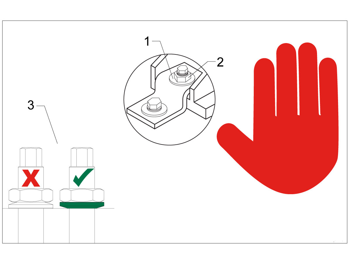
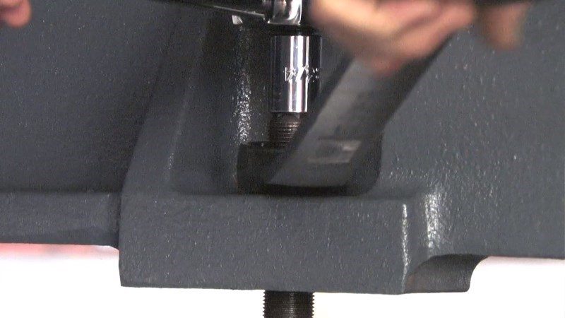
Note: The washers [1] and nuts [2] are installed during shipping and should be saved for installation and not be discarded.

Note: The washer orientation [3] is important.  The conical part of the washer should be against the casting,  see illustration.

Remove Rust Inhibitor

To safely and effectively remove rust inhibitor from way covers and other non-painted surfaces:

Initial Scraping

  • Use a plastic scraper to remove the bulk of the rust inhibitor.
  • Avoid using metal tools to prevent scratching or damaging the surface.

 Important: Do not use scotch-brite or metal scrapers, these will scratch the way covers.

Chemical Cleaning

  • Spray the affected areas with a heavy-duty citrus cleaner or Simple Green.
  • Ensure full coverage of all non-painted surfaces coated with rust inhibitor.

Soak Time

  • Allow the cleaner to soak for several minutes to loosen remaining residue.

Wipe Down

  • Use a clean shop towel to thoroughly wipe off the softened rust inhibitor.

Rust Proofing

  • Apply mineral spirits or WD-40 to all exposed metal surfaces to prevent future rust formation.

Important: Always wear gloves and eye protection when handling chemical cleaners. Dispose of used towels and cleaning agents according to local environmental regulations.

 Important: To avoid any contamination of the way cover seals with the sticky residue. Do not move any of the axes until all the rust inhibitor has been removed.

Rust Inhibitor - Safety Data Sheet (SDS)

Air Connection

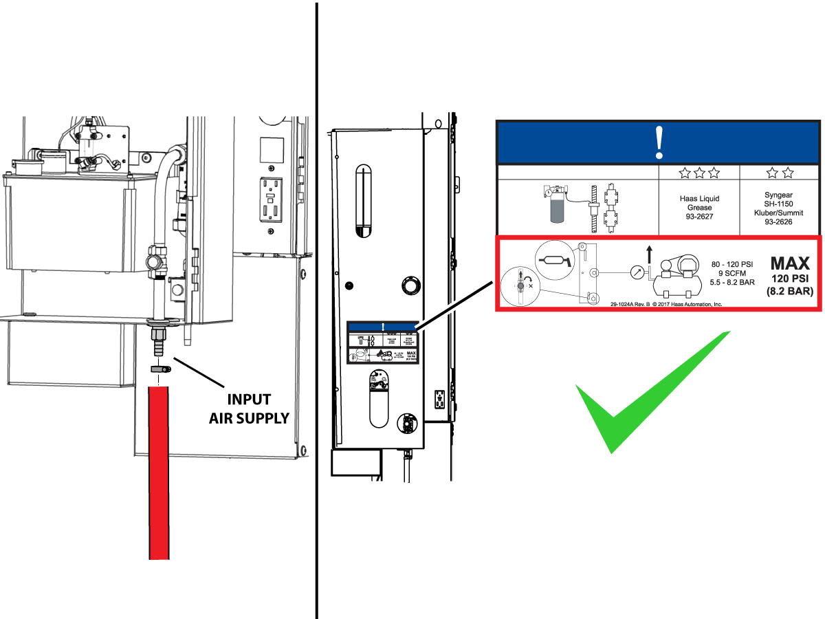
Connect the air supply at the lube panel.

 Note: For air requirements refer to the decal that is located on the lube cabinet door.

Follow the Air Gun and Hose Installation procedure to install or replace the Air Gun.

 Note: Some installation kits will come with a spare air gun assembly.

Electrical Installation

 DANGER: Working with the electrical services required for CNC machines is extremely hazardous and can result in serious injury or death.

Before connecting line wires to the CNC:

  • Turn off all power to the machine at the source.
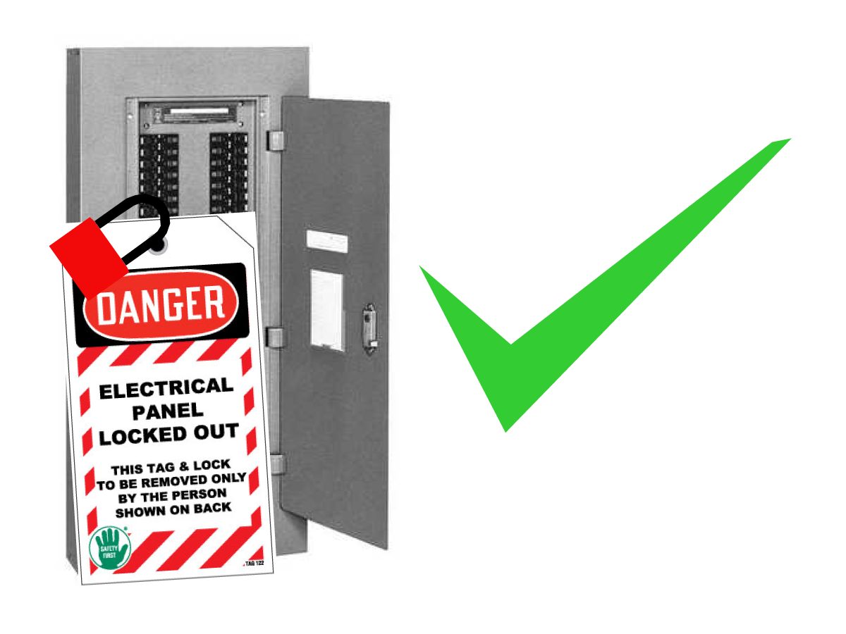
  • Perform a Lockout-Tagout (LOTO) procedure to ensure the power remains off during service.
  • Verify that power has been disconnected by using an AC voltage detector on all incoming lines.

If you are uncertain about how to safely disconnect power or perform LOTO procedures:

  • Do not proceed.
  • Contact qualified personnel or obtain appropriate assistance before continuing.

Failure to follow these precautions may result in electrical shock, equipment damage, or fatal injury.

1

Initial Control Inspection

Danger: At this point, there should be no electrical connection to the machine. Electrical panel must be closed and secured. When main switch is on, there is HIGH VOLTAGE throughout the electrical panel (including the circuit boards and logic circuits) and some components operate at high temperatures. Therefore, exercise extreme caution when working in the panel.

  • Set the main breaker switch at the upper right of the electrical panel on the back of the machine to OFF.
  • Using a screwdriver, unlock the two latches on the panel door, unlock the cabinet with the key and open the door.
  • Take sufficient time to check all the components and connectors associated with the circuit boards. Look for any cables that have become disconnected, look for any signs damage and loose parts in the bottom of the panel box. If there are any signs that the machine was mishandled, call the factory before proceeding.

2

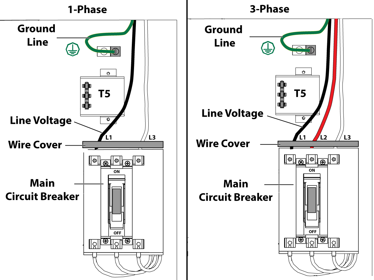
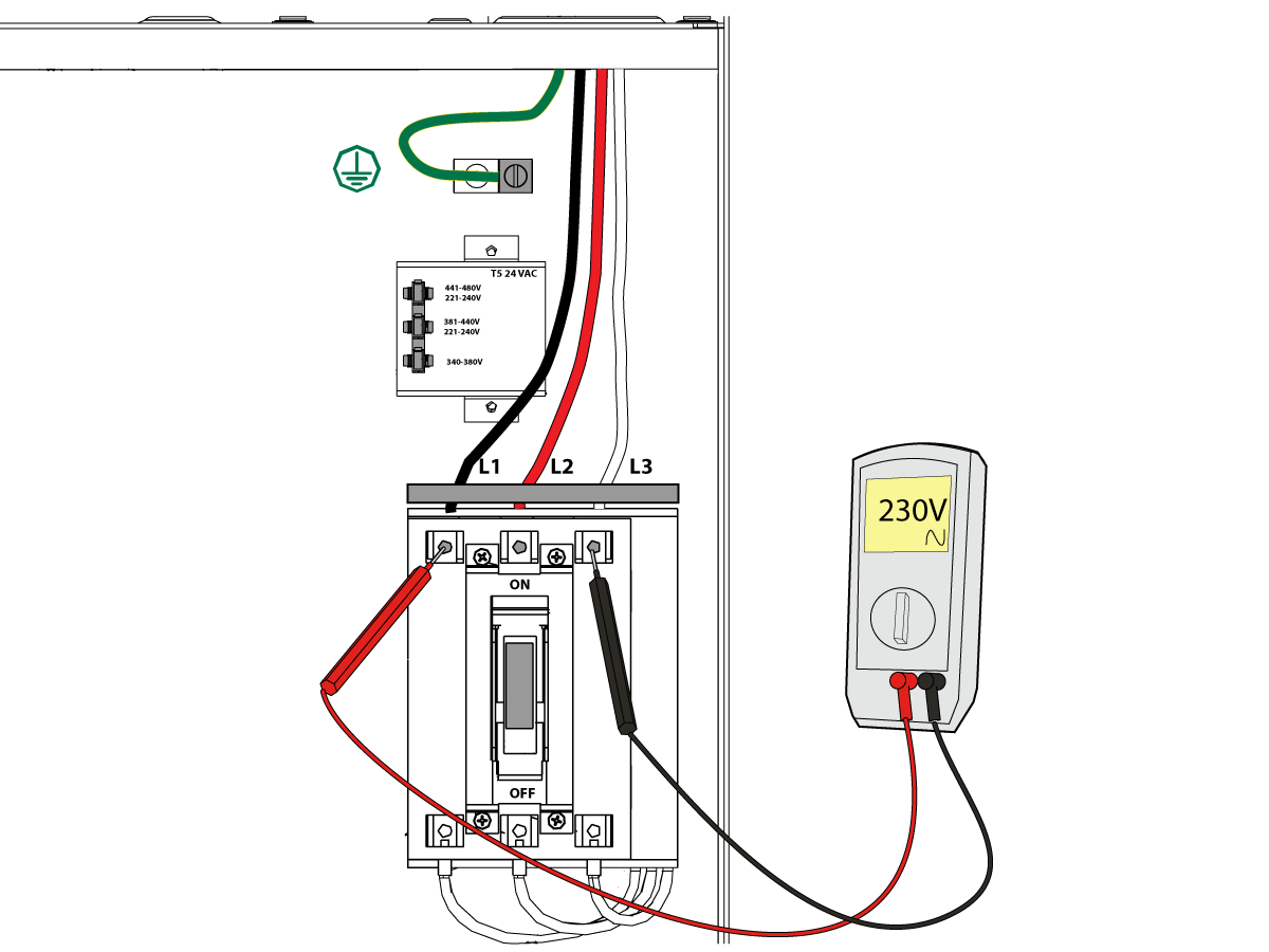
1-Phase Machines: Insert each power lead into the wire cover.  Connect the two power leads to L1 and L3 terminals on top of the main circuit breaker.

3-Phase Machines: Insert each power lead into the wire cover.  Connect the three power leads to L1, L2 and L3 terminals on top of the main circuit breaker.

Connect the separate ground line to the ground bus to the left of the terminals.

For 3-phase machines, check to see what type of power configuration is supplying the machine. Take voltage measurements of each power lead to ground line. Then refer to RD0084 - Input Power Configurations to determine which power lead should be connected to the L1 terminal based of the voltage readings and power configuration.

Refer to Haas Main Circuit Breaker - Torque Specifications for what value to torque the circuit breaker power leads.

 Note: Make sure that the leads actually go into the terminal-block clamps . (A poor connection will cause the machine to run intermittently or have other problems, such as servo overloads.) To check, simply pull on the wires after the screws are tightened.

3

After the line voltage is connected to the machine, make sure that main circuit breaker (at top-right of rear cabinet) is OFF . Remove the Lockout / Tagout and Turn ON the power at the source. Using a digital voltmeter and appropriate safety procedures: 

1-Phase Machines: Measure the AC voltage across L1 & L3 at the main circuit breaker.  The AC voltage must be between 220 - 250 volts .
Note: Lower or higher than this voltage can generate low/high voltage alarms.

3-Phase Machines : Measure the AC voltage between all three pair phases at the main circuit breaker. 

The AC voltage must be between 195 and 260 volts (360 and 480 volts for high voltage option).

SMinimill - Reboot: The AC voltage must be between 198 and 242 volts for machines without a high voltage transformer.  Refer to the Minimill/SMinimill - Identification document.

 Note: Wide voltage fluctuations are common in many industrial areas; minimum and maximum voltage supplied to a machine while it is in operation must be known. U.S. National Electrical Code specifies that machines should operate with a variation of +5% to -5% around an average supply voltage. If problems with line voltage occur, or low line voltage is suspected, an external transformer may be used. If you suspect voltage problems, voltage should be checked every hour or two during a typical day to be sure it does not fluctuate more than +5% or -5% from an average.

4

Important: With the main circuit breaker turned OFF.

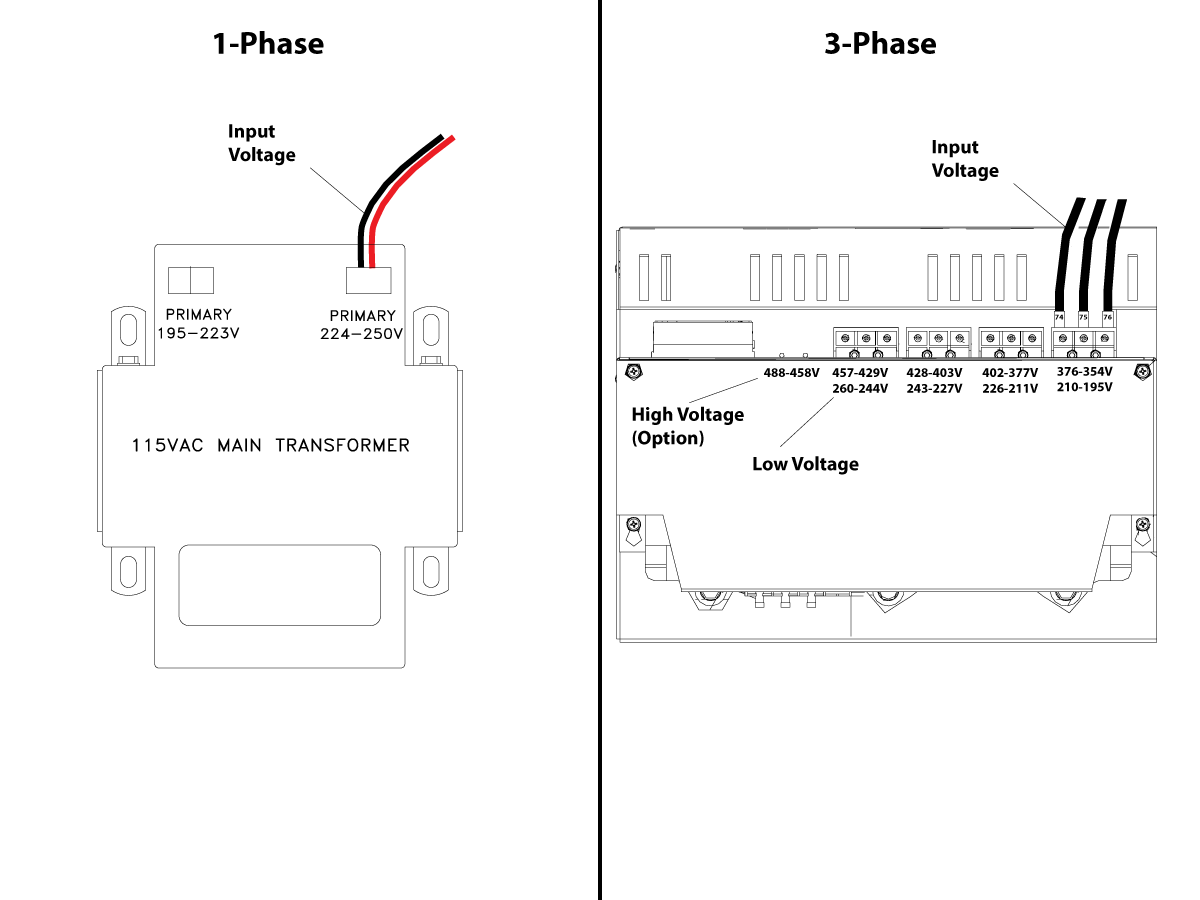
Check the transformer taps at the bottom-right corner of the rear cabinet.

1-Phase Machines: The input voltage cable must be moved to the connector which corresponds to the average voltage measured in the above step.

3-Phase Machines:  The input voltage cables labeled 74, 75, and 76 must be moved to the terminal block triple which corresponds to the average voltage measured in the above step.

5

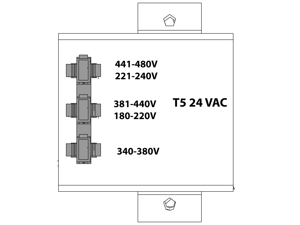
Transformer T5 supplies 24VAC used to power the main contactor. There are two versions of this transformer for use on a 240 and 400V machines. The 240V transformer has two input connectors located about two inches from the transformer, which allow it to be connected to either 180-220V or 221-240V.

Users that have 220V-240V RMS input power should use the connector labeled 221-240V, while users with 190-220V input power should use the connector labeled 180-220V. Failure to use the correct input connector will result in either overheating of the main contactor or failure to reliably engage the main contactor.

The 480V (option) T5 transformer has three input connectors, labeled 340-380V, 381-440V and 441-480V.

Users with 340-380V 50/60Hz power should use the 340-380V connector while users with 380V-440V 50/60Hz power should use the 381-440V connector.

Important: Set the main circuit breaker to ON. Check for evidence of problems, such as the smell of overheating components or smoke. If such problems are indicated, immediately set the main circuit breaker to OFF and call the factory before proceeding.

After the power is on, measure the voltage across the bottom terminals on the main circuit breaker. It should be the same as the measurements where the input power connects to the main breaker. If there are any problems, check the wiring.

6

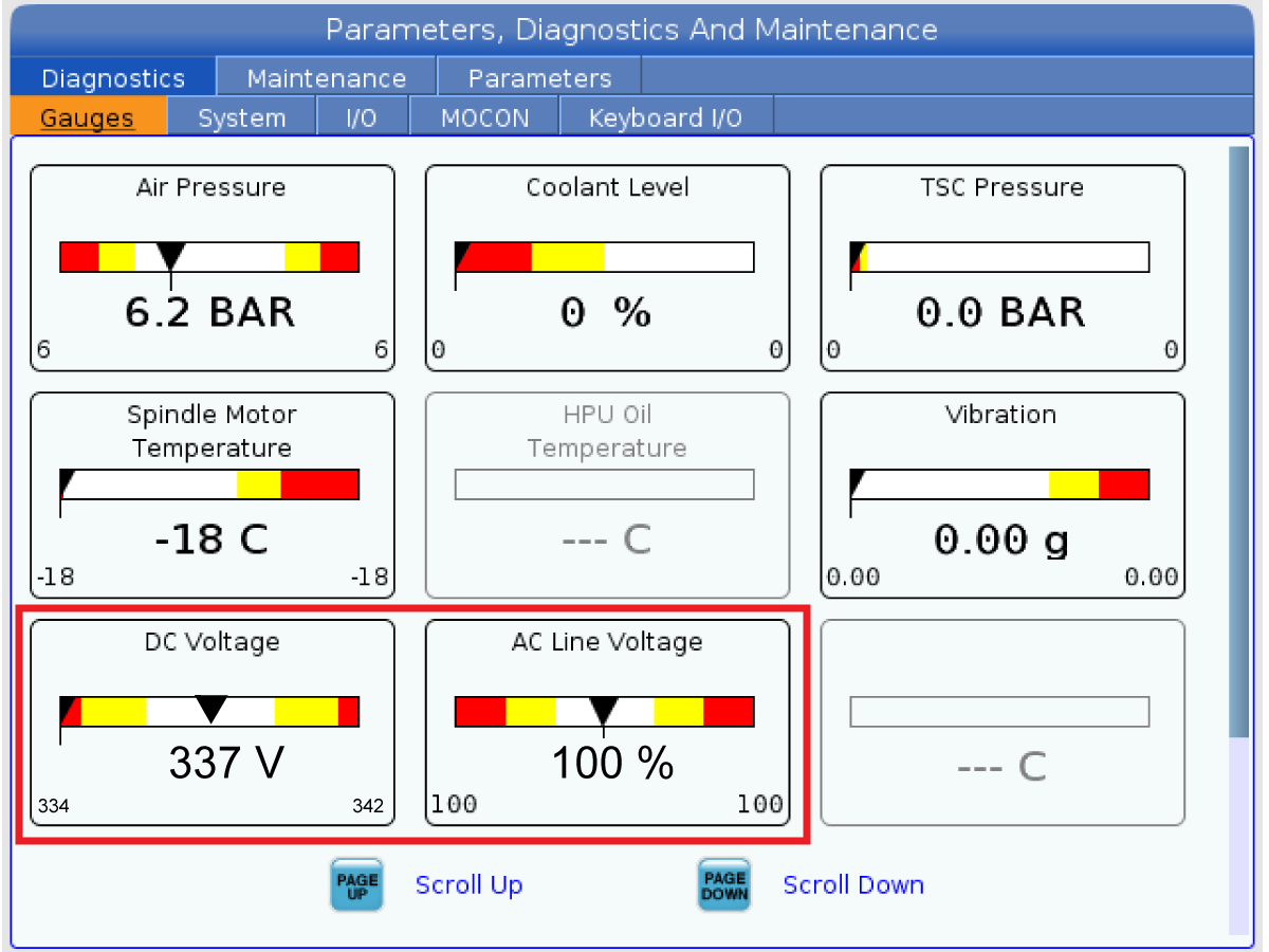
Apply power to the control by pressing the Power-On switch on the front panel.

Check the DC Voltage and AC Line Voltage gauges in Diagnostics. The DC Voltage gauge must read between 310 - 360V. The AC Line Voltage must be between 90 and 105 percent. If the voltage is outside these limits, turn off the power and recheck steps 2 and 3. If the voltage is still outside these limits, call the factory.

7

Electrical power must be phased properly to avoid damage to your equipment. The Power Supply Assembly PC board incorporates a "Phase Detect" circuit with neon indicators. When the orange neon is lit (NE5), the phasing is incorrect. If the green neon is lit (NE6), the phasing is correct. If both neon indicators are lit, you have a loose wire; check the connections. Adjust phasing by setting the source power to off and then swapping L1 and L2 of the incoming power lines at the main circuit breaker.

Danger: ALL POWER TO CNC MUST BE TURNED OFF LOCKOUT-TAGOUT AT THE SOURCE PRIOR TO ADJUSTING PHASING. ALWAYS DOUBLE CHECK THE INCOMING LINES WITH AN AC VOLTAGE DETECTOR.

Turn off the power and set the main circuit breaker to OFF. Close the door, lock the latches, and turn the power back on.

Remove the key from the control cabinet and give it to the shop manager.

8

Activation

When the machine is properly placed and connected to both air and electrical power, it is ready for final installation (removing shipping blocks, leveling, spindle sweep, etc.) and software activation. The HFO service technician does this. Contact the local HFO to schedule the work.

IMPORTANT:  Machines equipped with motion sensors must be rough‑leveled before attempting to arm the motion sensor.  For detailed instructions, refer to Service Notification - SA0007.  Access to this document is restricted to Haas Factory Outlet personnel.

Shipping Brackets Removal

1

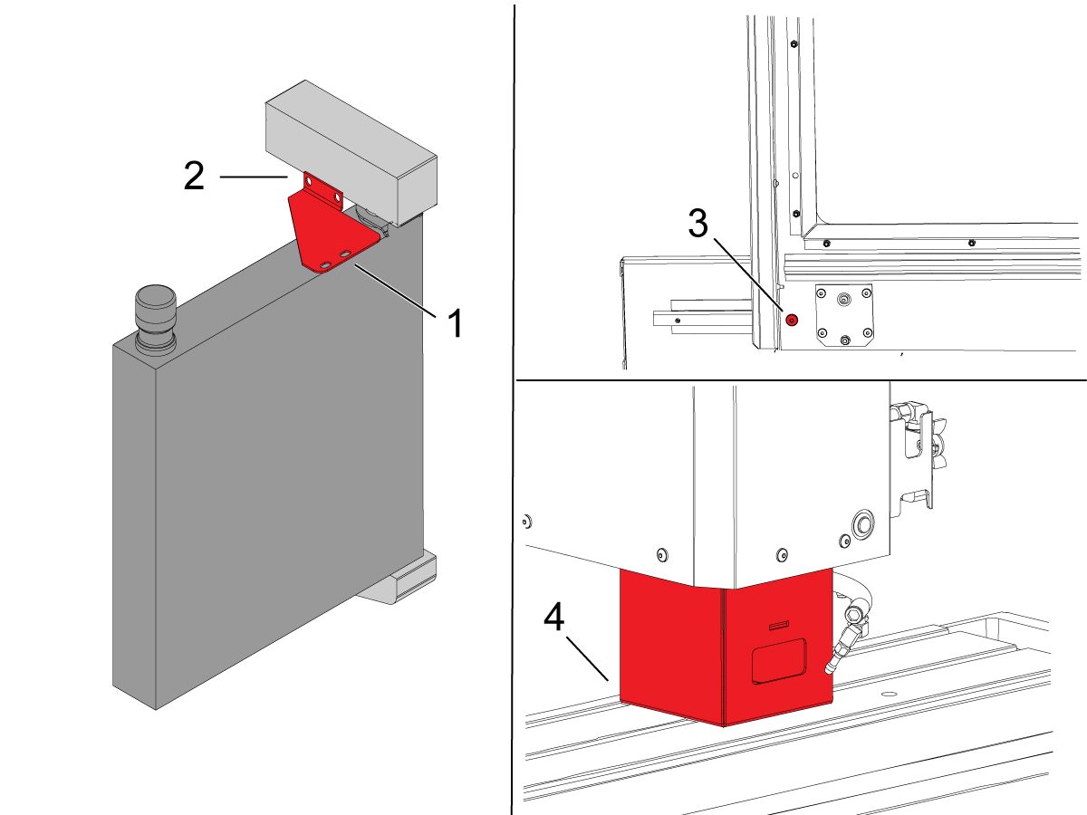
Távolítsa el a függő szállítókeretet.

2

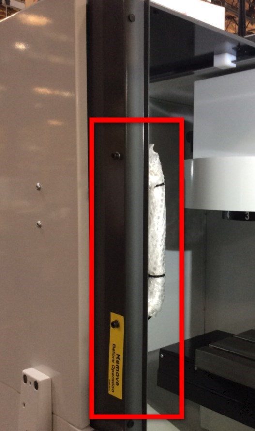
Távolítsa el az üzemeltető ajtó szállítókeretét.

3

Szerelje vissza az ajtófogantyút a kezelői ajtó külsejére.

4

Nyomja meg [POWER ON] és kövessük a képernyõn megjelenõ utasításokat.

Nyomja meg a [HAND JOG] És [Z+] Gombok. Jog a Z-tengely felfelé.

Távolítsa el a 40T orsós szállítókeretét.

Machine Leveling

1

Nulla az egyes tengelyt egyenként visszaáll, vagy nyomja meg. Menjen végig a Simítási folyamaton.
A megfelelő gépszint elérése érdekében ismételje meg ezeket a lépéseket.

2

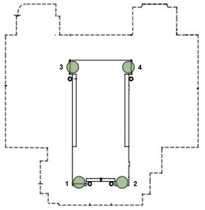
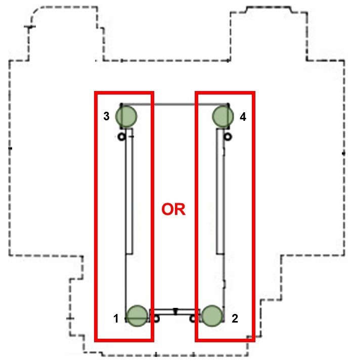
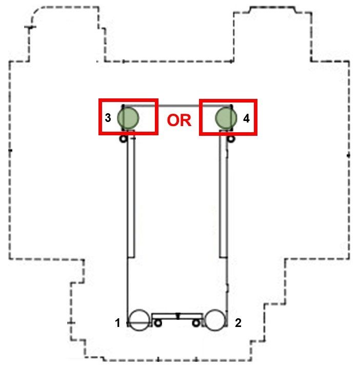
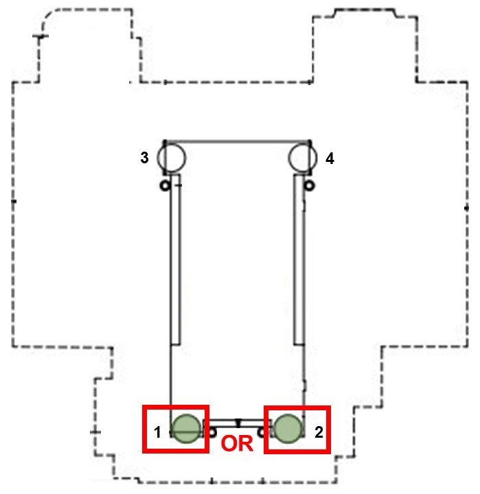
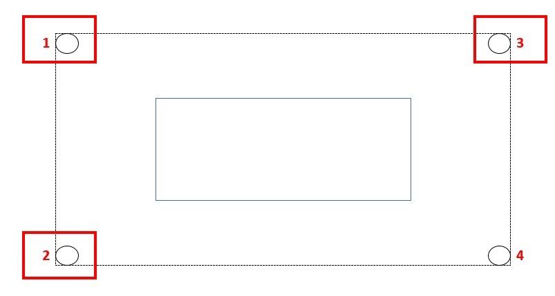
A Négysarok simító csavarok segítségével állítsa be a gép magasságát [1, 2, 3, 4] – 3" +/-0,5" (75 mm +/- 10 mm) a padló fölött. Kapcsolja be az egyes csavart, így azok egyenlő feszültséget.

Jog az X-tengely és az Y-tengely a közepén az utazás, középre az asztalra.

Megjegyzés: A képen a DM-2 elrendezése látható, de ugyanez a folyamat vonatkozik minden DM, DT, minimaró és szupermini maró gépre négy szintezőcsavarral. Ha gépén hat vagy több simító csavar van, kérjük, olvassa el a következő témakört:

VMC Szintbeállító

3

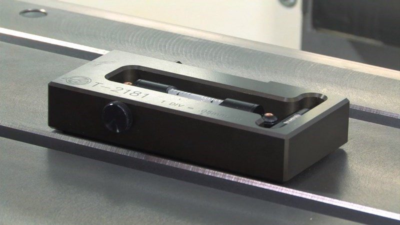
Tisztítsa meg az asztal felületét és a Szintbeállító eszközt (T-2181), és a folytatás előtt ellenőrizze a Simító eszköz kalibrálását.

Vigye a szintet a raklap középpontjában, az X tengellyel párhuzamosan.  Használjon t-slot a nyomvonal.

Megjegyzés: a helyzet a buborék.

Helyezze át a szintet elforgatásával 180 fok. A buboréknak ugyanazt az olvasást kell megjelenítnie, mint korábban.

Ha a mérési értékek több, mint egy osztás, vissza a szintet Haas a kiigazítást, és nem használja, hogy szinten a gép.

4

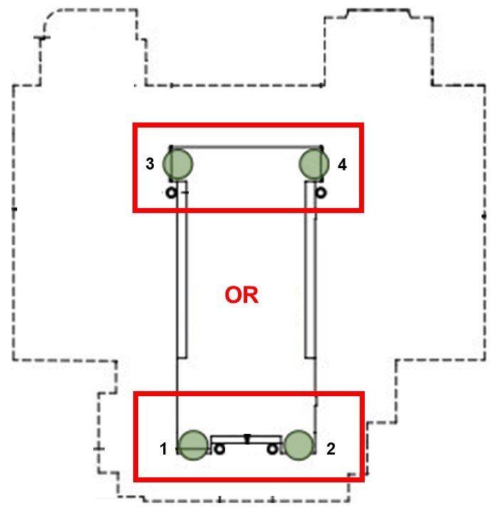
A saroksimító csavarok [1,2] vagy [3,4] kiigazítása az Y-tengellyel párhuzamos buborék középre igazításáig.

Ez a szint a gép elölről hátra.

Mindig emelje fel a gép alsó oldalát, hogy fenntartsa a hűtőközeg tartálynak (ha van) és állítsa be a két simító csavart az adott oldalon egyenlő összeggel.

5

Saroksimító csavarok beállítása [1,3] vagy [2,4] az X-tengellyel párhuzamos buborék középre igazításáig.

Ez a szint a gép balról jobbra.

Ismét emelni az alsó oldalán a gép, és állítsuk be a két simító csavarok az oldalon azonos összegű.

6

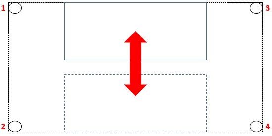
Tartsa a szint ugyanabban a helyzetben, és az Y-tengely jog, hogy a táblázat a gép eleje.

Megjegyzés: a helyzet a buborék.

Jog az Y-tengely keresztül teljes utazás, megállás az oszlopban. Nézze meg, hogy a gép melyik hátsó sarka a legalacsonyabb, ahogy azt a Simító eszköz mutatja.

Emelje fel a legalacsonyabb hátsó sarkot a sarokkiegyenlítő csavar [3] vagy [4] beállításával, amíg a buborék a szint köré kerül.

7

Jog az Y-tengely vissza szerte a teljes utazás, így az asztal előtt a gép. Nézd meg, hogy melyik első sarokban a legalacsonyabb, mint azt a szintet.

Emelje fel a legalsó sarkot a saroksimítás csavar [1] vagy [2] beállításával, amíg a buborék a szint köré kerül.

Ismétel lép 6 és 7, mozgó a asztal hát és előre keresztül a teli utazik-ból Y betű-tengely, emelés a a legalacsonyabb sarok minden alkalommal.

Folytassa ezt a folyamatot addig, amíg az Y-tengelyes utazás mindkét végén nem olvas nullát.

Spindle Sweep Check

1

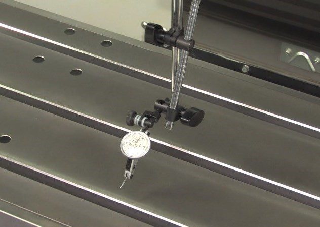
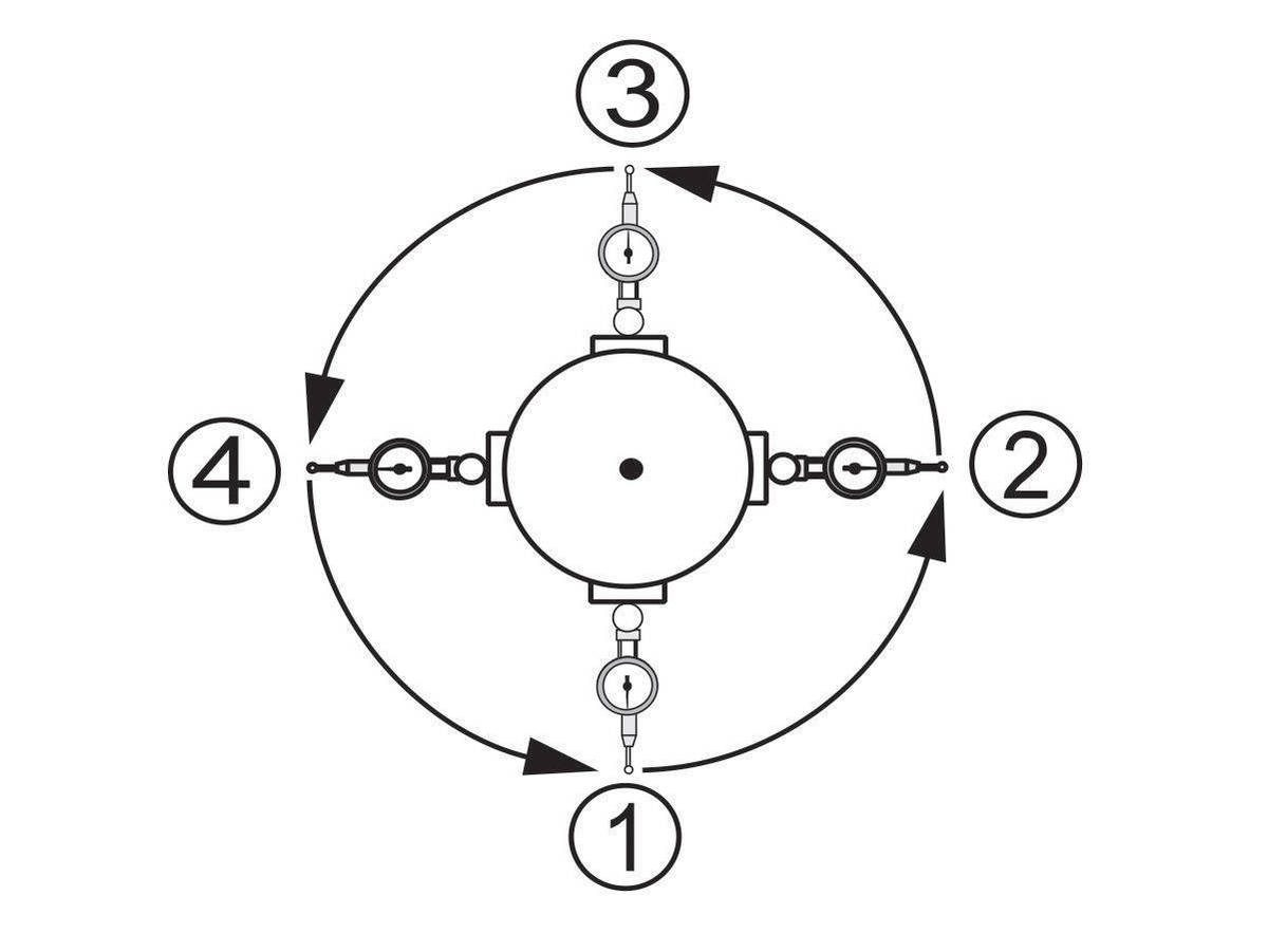
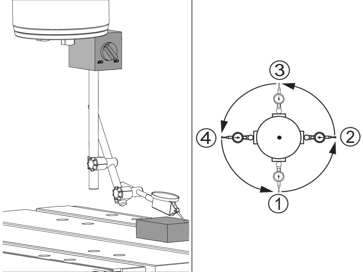
Jog a Z tengely közepén az utazás. Rögzítse a tesztkijelzőt a mágneses talpra és rögzítse a mágneses talpat az orsó aljára.

Helyezze el a tesztkijelzőt 10" (250mm) átmérőjű kör az asztal közepére.

Helyezze el a táblázatot úgy, hogy a teszteredék az asztalon maradjon (nem a t-slot alatt), amikor a gép elülső és oszlop oldalait is felnéz.

Az indikátort a gép eleje felé fordítva, a Z tengely tizedik (0,0001"), és a tesztindikátort lefelé kell vinni a táblázathoz.

Nullázje a kijelzőt.

2

Fordítsa az orsó kézzel, és hogy egy olvasó minden 90 fok, hogy két érték mentén mind az X-tengely és az Y-tengely.

Az egyes tengelyek jelzőértékei közötti különbség nem haladhatja meg a. 0,0005" (0,013 mm).

3

Zárolja a simító csavarokat úgy, hogy a rögzítő anyát szigorítják, miközben a simító csavart tartja.

Gyõzõdjön meg róla, hogy a simító csavar nem mozog ebben a folyamatban.

Ha az orsó söpörni, győződjön meg róla, a szint a gép helyes.

Ahhoz, hogy egy indepth útmutatót, hogyan kell elvégezni ezt az eljárást, kérjük, olvassa el:

VMC orsó söpörni

Lubrication Verification

1

Run the spindle run-in program.

 Note: For 10K spindles and above use a balanced tool holder

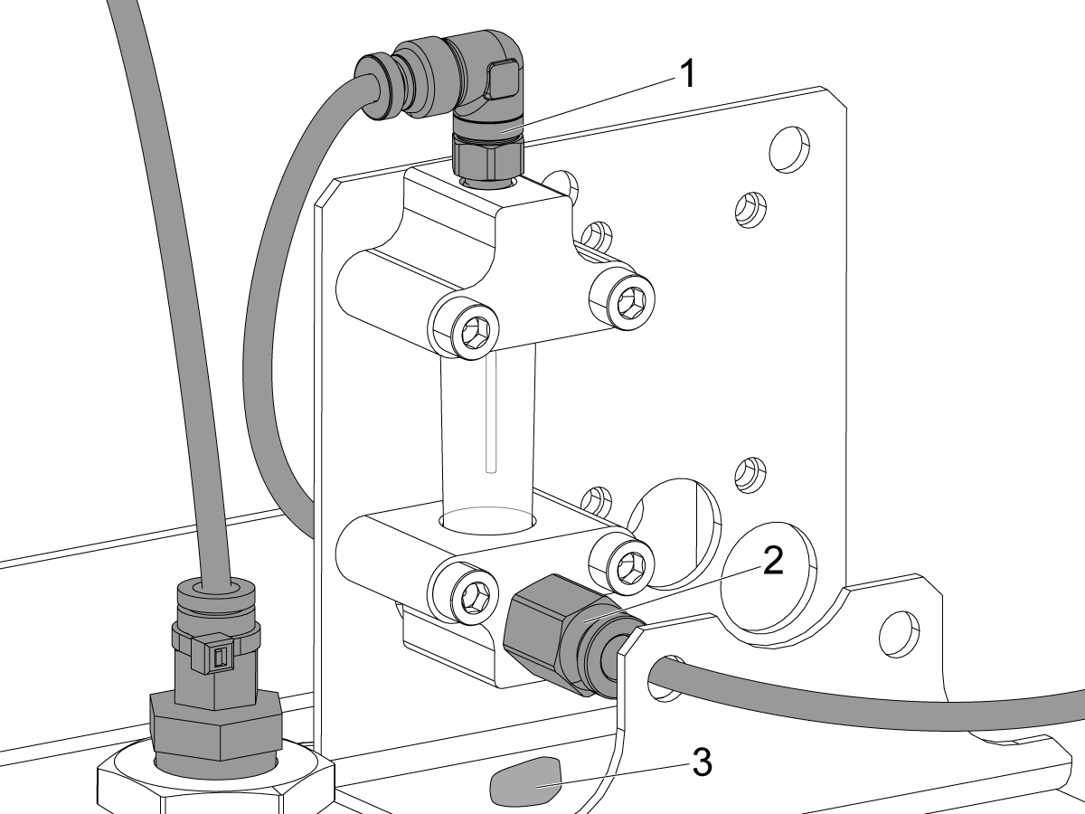
Examine the sight glass, make sure the correct number of drops are fall through the sight glass.

Examine the fittings [1,2] on top of the oil pump tank.

The oil collects on top of the oil pump tank [3] either behind or in front of the sight glass bracket, underneath the leaking fitting.

Tighten any leaking fittings.

2

Go to the Maintenance tab.

Press [F2] to cycle an axis lubrication test.

Inspect the gauge on the lubrication system.  Make sure it holds pressure.

MiniMill-EDU Machines

1

MiniMill-EDU gépekhez:

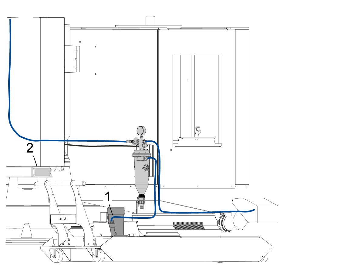
Ha a gép rendelkezik a 45 gallonos hűtőközeg-tartály terepen telepített opcióval 93-1001072, akkor a forgácsleválasztót és a hűtőközegsínt is telepíteni kell.

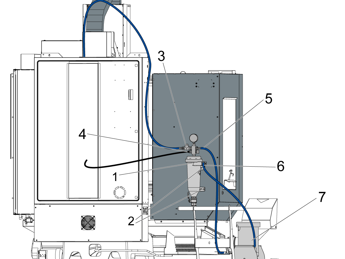
Szerelje be a hűtőközeg-szűrőt [1] úgy, hogy az FBHCS-sel [2] a burkolatlemez hátuljához rögzíti. Ezután csatlakoztassa a tömlőket, és vezesse el őket az alábbiak szerint:

Vezesse a kék hűtőközeg-tömlőt [3] a forgácsszeparátor bal felső részétől az orsófejig.

Vezesse a fekete hűtőközeg-vezetéket [4] a nyomócsatlakozó szerelvénytől a hátsó Y-tengely járt burkolat lemosó csatlakozójáig. A tömlőt az oszlop öntvényén keresztül kell vezetni.

Vezesse a kék hűtőközeg-tömlőt [5] a forgácsszeparátor szerelvény jobb felső részétől a hűtőközeg mosópisztoly tartójáig.

Csatlakoztassa a kék hűtőközeg-tömlőt [6] a forgácselválasztó közepétől a hűtőközeg-szivattyúhoz [7].

2

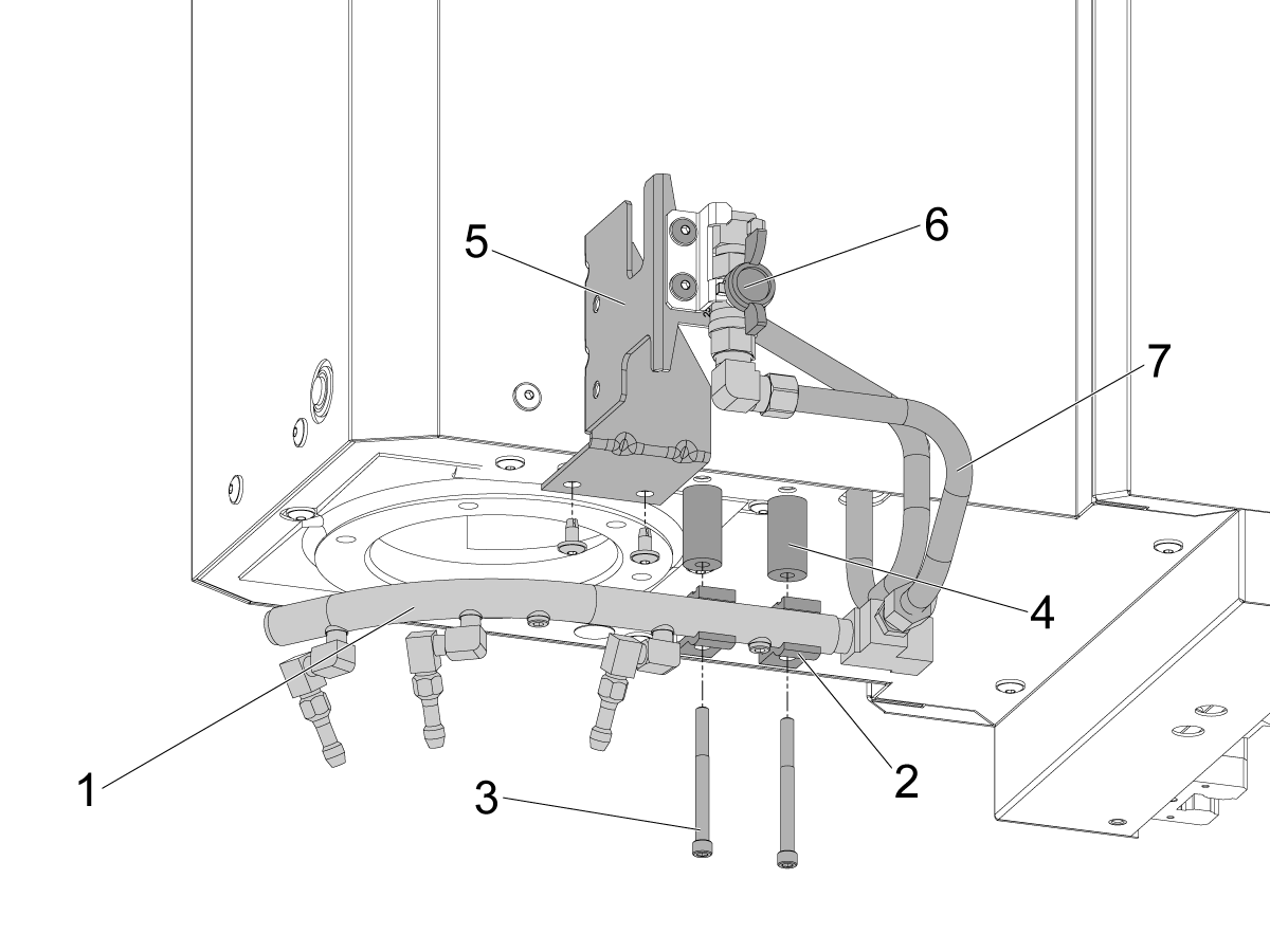
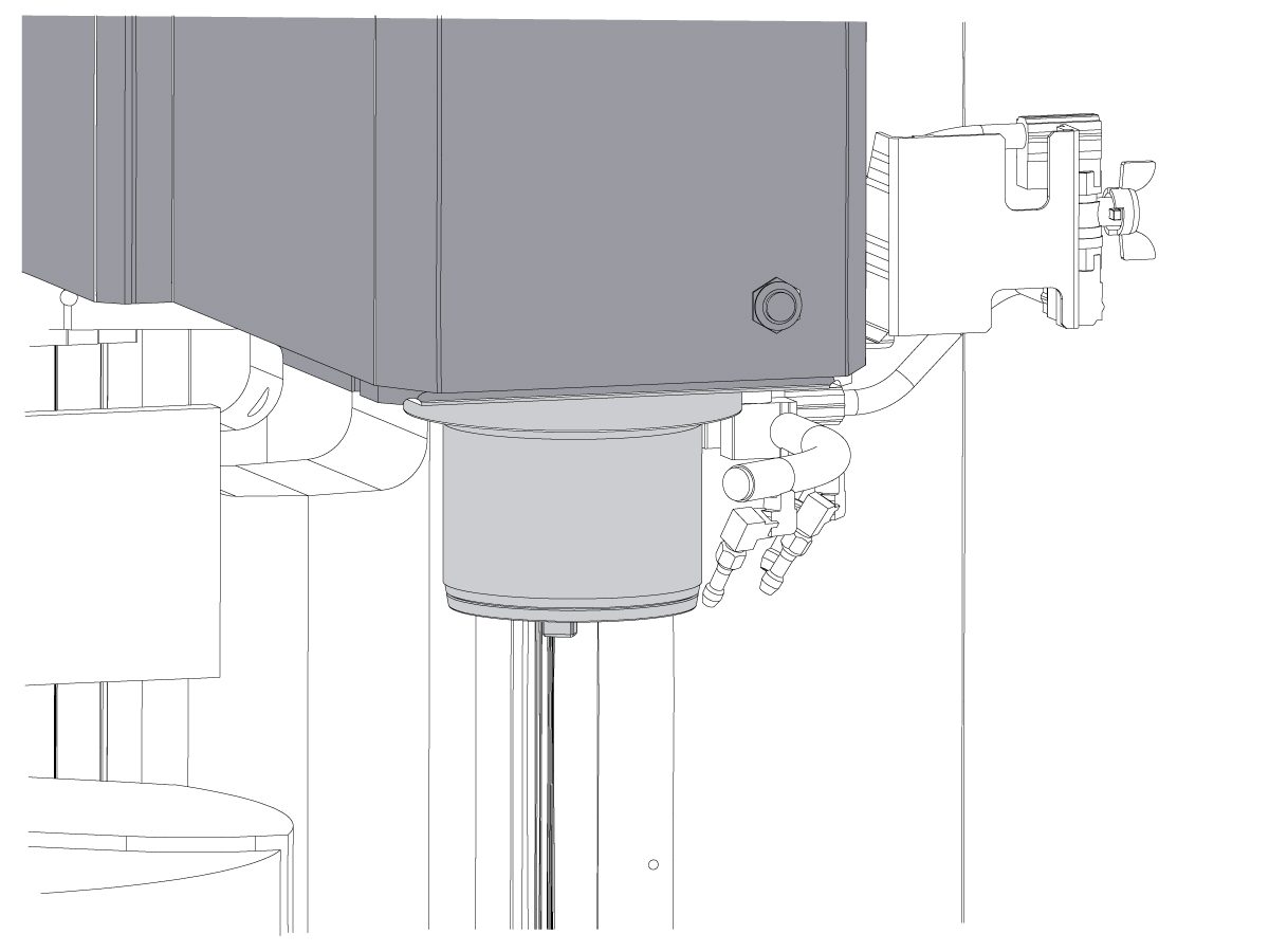
Minimaró-EDU gépeknél:

Szerelje fel a hűtőközeg-gyűrű szerelvényt úgy, hogy rögzíti az orsófejhez.

Használja a hosszú SHCS-t [3] és a 2 hűtőközeg-sínbilincset [2] a hűtőközeg-sínszerelvény [1] telepítéséhez.

Használja a távtartókat [4] a hűtőközeg-sín és az orsófej között.

Rögzítse a P-COOL rögzítőkonzolt [5] az orsófejhez a BHCS segítségével.

Vezesse a tömlőt az orsófejtől a hűtőközeg-szelepig [6].

Vezesse a másik tömlőt [7] a szeleptől a hűtőközeg-sínig

Megjegyzés: A hűtőközeg szivárgásának megelőzése érdekében győződjön meg arról, hogy minden szerelvény meg van húzva.

Megjegyzés: Ha a gép a gyárból a 45 gallonos hűtőközeg opcióval rendelték meg, akkor ezekre a lépésekre nincs szükség. Ezt csak a 93-1001072 helyszíni telepítőkészletnél kell elvégezni. Ellenőrizze, hogy az opció működik-e a következő fejezetben található tesztelést követően.

Option Installation Guides

Ellenőrizze és tesztelje, hogy az összes lehetőség megfelelően telepítve van-e.

Távirányítós léptetőfogantyú (RJH-Touch) - Telepítés
Opcionális Wi-Fi kamera telepítés
Kényelmi csomag
Kiegészítő hűtőközeg-szűrő
P-COOL telepítés
PulseJet telepítés
HAAS olajfölözőgép
Asztal munkatér világítás
Szerszám légbefúvás
Automatikus légfúvó pisztoly

Final Testing

1

Csatlakoztassa a hűtőfolyadék-szivattyú és a through orsó hűtőközeg (TSC) szivattyú (ha van felszerelve).

Csatlakoztassa a kék hűtőközeg-csövet a szűrő bemenetről a hűtőfolyadék szivattyú aljzatba.

Csatlakoztassa a hűtőközeg szivattyút az alacsony nyomású hűtőközeg dugó.

Csatlakoztassa a TSC szivattyút a kis lila hűtőfolyadék tömlő.

Dugja be a TSC szivattyút a nagynyomású hűtőfolyadékhoz.

Dugja be a hűtőfolyadékszint érzékelőt és az egyéb kapcsolódó érzékelőket a megfelelő dugaszokba.

2

Tesztelje az árvíz hűtőközeg.

Nyissuk ki a szelepet a hűtőközeg gyűrűjéhez, és a vizsgálat előtt Csukjuk be a kezelőajtót.

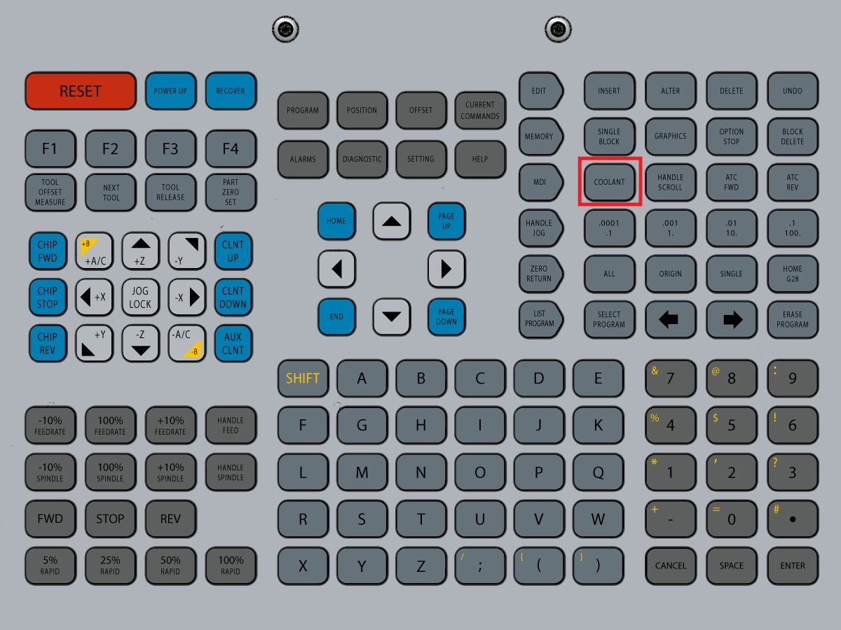
Nyomja meg a vezérlőn a [COOLNT] gombot. Hűtőközeg kell árvíz a fúvókák.

Nyomja meg [COOLNT] ismét megállítani az áramlást.

3

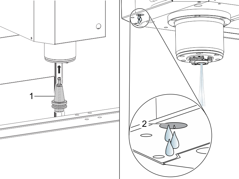
Az Orsóanyag hűtőfolyadéknak (TSC) a tesztelése (ha fel van szerelve).

Egy TSC eszköztartót [1] tesz a főorsóba.

Nyomja meg [AUX CLNT] a TSC indításához.

A helyes működés a következő:

  1. A hűtőközeg megfelelően áramlik a TSC szerszámtartóból.
  2. Néhány csepp áramlás a vákuum-generátor tömlőből [2].

Nyomja meg a [RESET] gombot.

4

Állítsa le az orsót.

Fuss a orsó fuss--ban műsor.

Orsó bejáratása

5

Tesztelje a chip Auger (ha fel van szerelve).

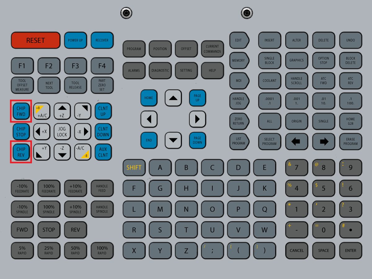
Nyomja meg a [CHIP FWD] és a [CHIP REV] gombokat a vezérlőn.

6

Tesztelje az ajtó zárak.

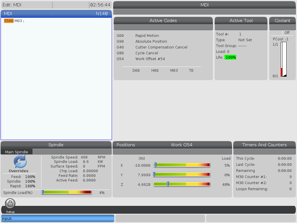
Nyomja meg [MDI], begépel S500 M03, majd nyomja meg [ENTER].

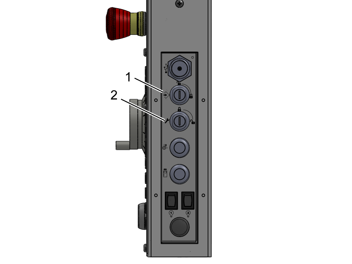
Gyõzõdjön meg róla, hogy a készülék nincs beállítva a függő állapotban, a medál oldalán található kulcskapcsoló ellenőrzésével.

Nyomja meg [CYCLE START] nyitott ajtóval. A gép azt mondja, hogy csukja be az ajtót, és nyomja [CYCLE START].

Nyomja meg [CYCLE START] zárt ajtóval. A reteszelőnek ki kell terjednie, és az orsó meg kell kezdeni spinning.

Próbálja meg megnyitni az ajtót az orsó spinning. Az orsó nem hagyja abba forog.

7

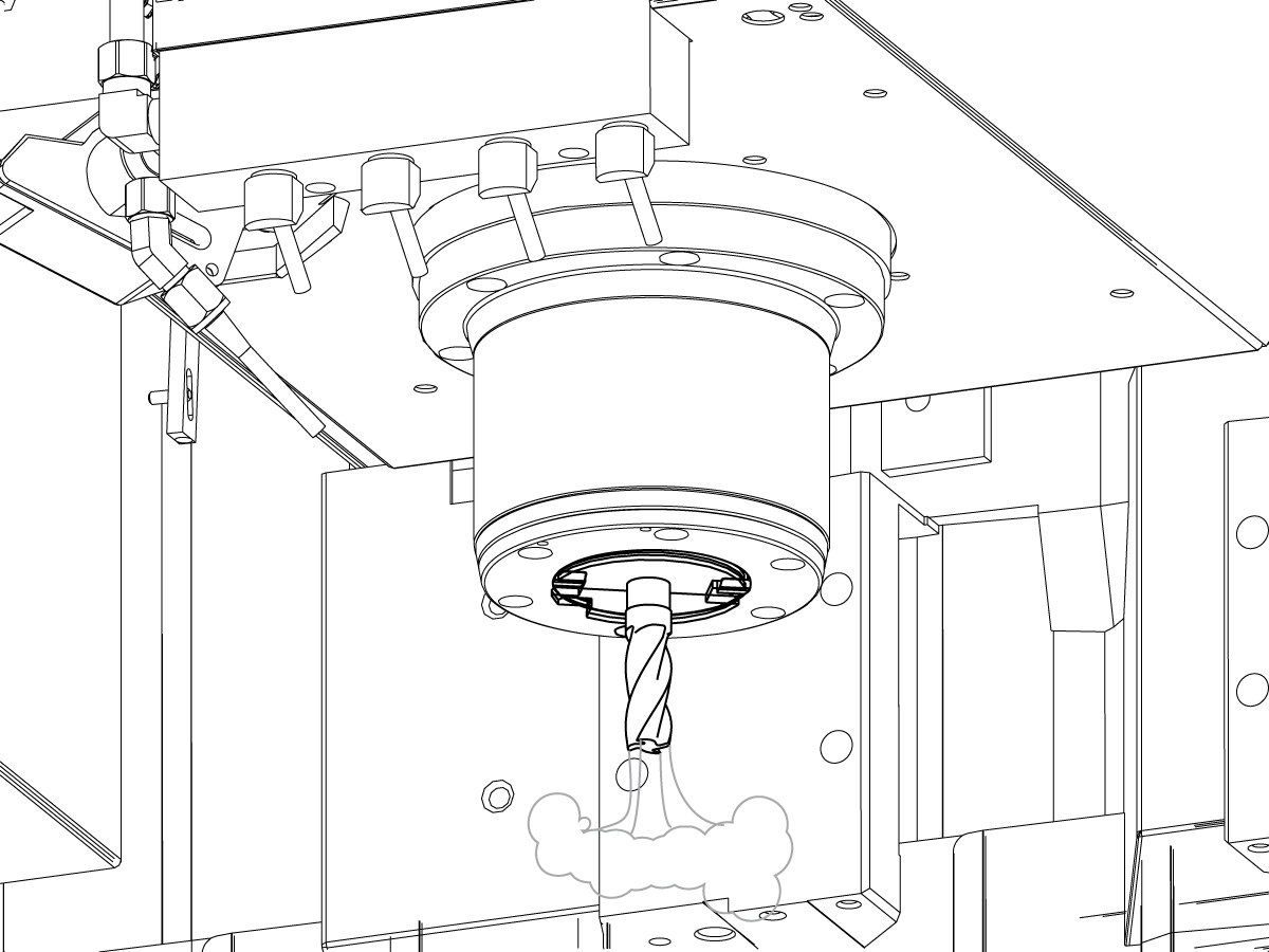
Teszt a keresztül-szerszám levegő robbanás (pánt) (ha felfegyverez).

Működtesse az alábbi kódot MDI módban:

M73;

G04 P5.;

M74

G04 P3.;

M99

M73 indítja a TAB-ot. M74 leállítja a TAB-ot.

Kézi működtetéséhez a TAB:

Nyomja meg a [AUX CLNT]gombot. Nyomja le a  [RIGHT] LEFELÉ-kurzorgombot.

A szerszám levegő robbanás indulások.

Nyomja meg a [AUX CLNT] gombot.

Az eszköz levegő robbanás leáll.

8

Tesztelje a Billentyűkapcsolókat.

Behelyez a beállít/fuss Bezár kulcs (#2007)-hoz leenged kulcs nyílást vág és fordít-hoz kulccsal be nem zárt helyzet.

Ellenőrizze, hogy a kulcs csak a zárolt pozícióból lehet-e eltávolítva.

Helyezze be a Memóriamegzárógombot (#2341) a felső kulcsnyílásba, és kapcsolja be a zárolt pozíciót.

Ellenőrizze, hogy a kulcs eltávolítható-e mindkét pozícióból.

A zárolt pozícióban lévő Memóriamegzárógomb segítségével ellenőrizze, hogy a beállítások vagy a programok módosításai nem történtek-e meg.

9

Ellenőrizze, hogy minden oldalelérési ablakra van-e telepítve ablakzár.

(Ez nem vonatkozik a DM és DT sorozatú gépeken rögzített oldalsó ablakra.)

Ellenőrizze, hogy a reteszt minden ablakot lefolytat-e, hogy az ablakot a fel helyzetbe tartsa.

Ellenőrizze, hogy az ablakzárak minden oldalablakra telepítve vannak-e.

Ellenőrizze, hogy a Windows-zárolás le van-e zárva a pozícióból.

Install and Calibrate WIPS

1

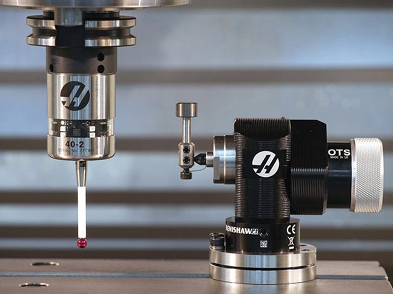
Telepítsen és kalibrált vezeték nélküli, intuitív Szondarendszer (WIPS) (ha fel van szerelve).

A részletes útmutató a WIPS szerelés és kalibrálás, kérjük, olvassa el:

WIPS – Összeszerelés

3.2 Reeboot MM/SMM telepítés

Recently Updated

Minimaró/szupermini maró – Telepítés


Introduction

Ez az eljárás megmutatja, hogyan kell telepíteni az Újraindítási minimarót (MM), illetve a szupermini marót (SMM). A nem újraindított Minimaró vagy Szuper Minimaró telepítéséhez további információkért lásd a Minimaró / Szuper Minimaró - Telepítés eljárást. 

Annak meghatározásához, hogy milyen típusú Minimaró verzióval rendelkezik, tekintse meg  Minimaró/Szuper Minimaró – Gép verzió - Azonosító referenciadokumentumot.

Szükséges eszközök:

  • 3/4" Aljzat
  • 5/32", 1/4", 3/8" Hatszögletű Bitcsatlakozó
  • Ratchet
  • 3/4", 1,5" Csavarkulcs
  • Mérőszalag
  • 0,0005" vagy 1 mikron tesztindikátor és mágneses talp
  • T-2181 szolgáltató eszköz, SZINTBEÁLLÍTÓ eszköz vagy precíziós gépész, 0,0005" Osztály

Leveling Screws Hardware

Note: The washers [1] and nuts [2] are installed during shipping and should be saved for installation and not be discarded.

Note: The washer orientation [3] is important.  The conical part of the washer should be against the casting,  see illustration.

Remove Rust Inhibitor

To safely and effectively remove rust inhibitor from way covers and other non-painted surfaces:

Initial Scraping

  • Use a plastic scraper to remove the bulk of the rust inhibitor.
  • Avoid using metal tools to prevent scratching or damaging the surface.

 Important: Do not use scotch-brite or metal scrapers, these will scratch the way covers.

Chemical Cleaning

  • Spray the affected areas with a heavy-duty citrus cleaner or Simple Green.
  • Ensure full coverage of all non-painted surfaces coated with rust inhibitor.

Soak Time

  • Allow the cleaner to soak for several minutes to loosen remaining residue.

Wipe Down

  • Use a clean shop towel to thoroughly wipe off the softened rust inhibitor.

Rust Proofing

  • Apply mineral spirits or WD-40 to all exposed metal surfaces to prevent future rust formation.

Important: Always wear gloves and eye protection when handling chemical cleaners. Dispose of used towels and cleaning agents according to local environmental regulations.

 Important: To avoid any contamination of the way cover seals with the sticky residue. Do not move any of the axes until all the rust inhibitor has been removed.

Rust Inhibitor - Safety Data Sheet (SDS)

Air Connection

Connect the air supply at the lube panel.

 Note: For air requirements refer to the decal that is located on the lube cabinet door.

Follow the Air Gun and Hose Installation procedure to install or replace the Air Gun.

 Note: Some installation kits will come with a spare air gun assembly.

Electrical Installation

 DANGER: Working with the electrical services required for CNC machines is extremely hazardous and can result in serious injury or death.

Before connecting line wires to the CNC:

  • Turn off all power to the machine at the source.
  • Perform a Lockout-Tagout (LOTO) procedure to ensure the power remains off during service.
  • Verify that power has been disconnected by using an AC voltage detector on all incoming lines.

If you are uncertain about how to safely disconnect power or perform LOTO procedures:

  • Do not proceed.
  • Contact qualified personnel or obtain appropriate assistance before continuing.

Failure to follow these precautions may result in electrical shock, equipment damage, or fatal injury.

1

Initial Control Inspection

Danger: At this point, there should be no electrical connection to the machine. Electrical panel must be closed and secured. When main switch is on, there is HIGH VOLTAGE throughout the electrical panel (including the circuit boards and logic circuits) and some components operate at high temperatures. Therefore, exercise extreme caution when working in the panel.

  • Set the main breaker switch at the upper right of the electrical panel on the back of the machine to OFF.
  • Using a screwdriver, unlock the two latches on the panel door, unlock the cabinet with the key and open the door.
  • Take sufficient time to check all the components and connectors associated with the circuit boards. Look for any cables that have become disconnected, look for any signs damage and loose parts in the bottom of the panel box. If there are any signs that the machine was mishandled, call the factory before proceeding.

2

1-Phase Machines: Insert each power lead into the wire cover.  Connect the two power leads to L1 and L3 terminals on top of the main circuit breaker.

3-Phase Machines: Insert each power lead into the wire cover.  Connect the three power leads to L1, L2 and L3 terminals on top of the main circuit breaker.

Connect the separate ground line to the ground bus to the left of the terminals.

For 3-phase machines, check to see what type of power configuration is supplying the machine. Take voltage measurements of each power lead to ground line. Then refer to RD0084 - Input Power Configurations to determine which power lead should be connected to the L1 terminal based of the voltage readings and power configuration.

Refer to Haas Main Circuit Breaker - Torque Specifications for what value to torque the circuit breaker power leads.

 Note: Make sure that the leads actually go into the terminal-block clamps . (A poor connection will cause the machine to run intermittently or have other problems, such as servo overloads.) To check, simply pull on the wires after the screws are tightened.

3

After the line voltage is connected to the machine, make sure that main circuit breaker (at top-right of rear cabinet) is OFF . Remove the Lockout / Tagout and Turn ON the power at the source. Using a digital voltmeter and appropriate safety procedures: 

1-Phase Machines: Measure the AC voltage across L1 & L3 at the main circuit breaker.  The AC voltage must be between 220 - 250 volts .
Note: Lower or higher than this voltage can generate low/high voltage alarms.

3-Phase Machines : Measure the AC voltage between all three pair phases at the main circuit breaker. 

The AC voltage must be between 195 and 260 volts (360 and 480 volts for high voltage option).

SMinimill - Reboot: The AC voltage must be between 198 and 242 volts for machines without a high voltage transformer.  Refer to the Minimill/SMinimill - Identification document.

 Note: Wide voltage fluctuations are common in many industrial areas; minimum and maximum voltage supplied to a machine while it is in operation must be known. U.S. National Electrical Code specifies that machines should operate with a variation of +5% to -5% around an average supply voltage. If problems with line voltage occur, or low line voltage is suspected, an external transformer may be used. If you suspect voltage problems, voltage should be checked every hour or two during a typical day to be sure it does not fluctuate more than +5% or -5% from an average.

4

Important: With the main circuit breaker turned OFF.

Check the transformer taps at the bottom-right corner of the rear cabinet.

1-Phase Machines: The input voltage cable must be moved to the connector which corresponds to the average voltage measured in the above step.

3-Phase Machines:  The input voltage cables labeled 74, 75, and 76 must be moved to the terminal block triple which corresponds to the average voltage measured in the above step.

5

Transformer T5 supplies 24VAC used to power the main contactor. There are two versions of this transformer for use on a 240 and 400V machines. The 240V transformer has two input connectors located about two inches from the transformer, which allow it to be connected to either 180-220V or 221-240V.

Users that have 220V-240V RMS input power should use the connector labeled 221-240V, while users with 190-220V input power should use the connector labeled 180-220V. Failure to use the correct input connector will result in either overheating of the main contactor or failure to reliably engage the main contactor.

The 480V (option) T5 transformer has three input connectors, labeled 340-380V, 381-440V and 441-480V.

Users with 340-380V 50/60Hz power should use the 340-380V connector while users with 380V-440V 50/60Hz power should use the 381-440V connector.

Important: Set the main circuit breaker to ON. Check for evidence of problems, such as the smell of overheating components or smoke. If such problems are indicated, immediately set the main circuit breaker to OFF and call the factory before proceeding.

After the power is on, measure the voltage across the bottom terminals on the main circuit breaker. It should be the same as the measurements where the input power connects to the main breaker. If there are any problems, check the wiring.

6

Apply power to the control by pressing the Power-On switch on the front panel.

Check the DC Voltage and AC Line Voltage gauges in Diagnostics. The DC Voltage gauge must read between 310 - 360V. The AC Line Voltage must be between 90 and 105 percent. If the voltage is outside these limits, turn off the power and recheck steps 2 and 3. If the voltage is still outside these limits, call the factory.

7

Electrical power must be phased properly to avoid damage to your equipment. The Power Supply Assembly PC board incorporates a "Phase Detect" circuit with neon indicators. When the orange neon is lit (NE5), the phasing is incorrect. If the green neon is lit (NE6), the phasing is correct. If both neon indicators are lit, you have a loose wire; check the connections. Adjust phasing by setting the source power to off and then swapping L1 and L2 of the incoming power lines at the main circuit breaker.

Danger: ALL POWER TO CNC MUST BE TURNED OFF LOCKOUT-TAGOUT AT THE SOURCE PRIOR TO ADJUSTING PHASING. ALWAYS DOUBLE CHECK THE INCOMING LINES WITH AN AC VOLTAGE DETECTOR.

Turn off the power and set the main circuit breaker to OFF. Close the door, lock the latches, and turn the power back on.

Remove the key from the control cabinet and give it to the shop manager.

8

Activation

When the machine is properly placed and connected to both air and electrical power, it is ready for final installation (removing shipping blocks, leveling, spindle sweep, etc.) and software activation. The HFO service technician does this. Contact the local HFO to schedule the work.

IMPORTANT:  Machines equipped with motion sensors must be rough‑leveled before attempting to arm the motion sensor.  For detailed instructions, refer to Service Notification - SA0007.  Access to this document is restricted to Haas Factory Outlet personnel.

Shipping Bracket Removal

1

Távolítsa el a felső (x2) csavarokat [1], amelyek a vezérlőt zárolt helyzetben tartja.

Fordítsa ki a vezérlőt, hogy hozzáférjen a fennmaradó (x2) csavarokhoz [2], amelyek a vezérlő zsanérjának közelében találhatók, és távolítsa el azokat. 

Távolítsa el az üzemeltető [3] ajtaját helyén tartó vállcsavarokat. A csavarok elérése az összes gépen az üzemeltető ajtónyílásának segítségével. 

A gép belsejében távolítsa el a csavarokat, amelyek az orsó szállítókeretét [4] rögzítik az asztalhoz az orsó burkolatánál. 

 MEGJEGYZÉS::  Ezen a ponton nem lesz eltávolítható az orsó tartó. Távolítsa el a tartókeretet a gép bekapcsolása és az orsó felfelé léptetése után

Machine Leveling

IMPORTANT:  Machines equipped with motion sensors must be rough‑leveled before attempting to arm the motion sensor.  For detailed instructions, refer to Service Notification - SA0007.  Access to this document is restricted to Haas Factory Outlet personnel.

1

Clean and jog the table so the spindle is on the center of travel.

Place the level on top the table aligning the long vial to be parallel with the X-axis. Use the T-slots as reference.

The long vial on the level represents the X axis and the short vial on the level represents the Y axis. 

Loosen the (4x) leveling screws on the corners of the base. Make small adjustments  to leveling screws 1 and 3 to adjust the X axis level. After each adjustment, note the position of the  bubble in the short vial. 

If the position of the bubble in the short vial isn't centered, make adjustments to leveling screws 1 and 2 as required. 

Repeat this process until both bubbles are in their center positions. 

2

Adjust (x4) leveling screws to be snug against the ground. 

Jog the table towards the spindle column while observing the position of the bubble in the long vial. If the bubble is not centered, make a small adjustment to the lower corner 1 & 3 if titled towards the column end or on the higher corner 2 & 4 if tilted towards the operator end.

Repeat this process with the table on the other end of the machine. 

Spindle Sweep Check

1

Attach indicator to spindle head. Position the table and indicator to sweep a circle 10" in diameter.
 
Place a gauge block on the table.
 
Jog the spindle down and zero the indicator at Position 1. 
 
Using a gauge block every 90 degrees, check that the difference in these measurements don't exceed 0.0005". If it does, check the machine level.

Lubrication Verification

1

Run the spindle run-in program.

 Note: For 10K spindles and above use a balanced tool holder

Examine the sight glass, make sure the correct number of drops are fall through the sight glass.

Examine the fittings [1,2] on top of the oil pump tank.

The oil collects on top of the oil pump tank [3] either behind or in front of the sight glass bracket, underneath the leaking fitting.

Tighten any leaking fittings.

2

Go to the Maintenance tab.

Press [F2] to cycle an axis lubrication test.

Inspect the gauge on the lubrication system.  Make sure it holds pressure.

Convenience Package Install

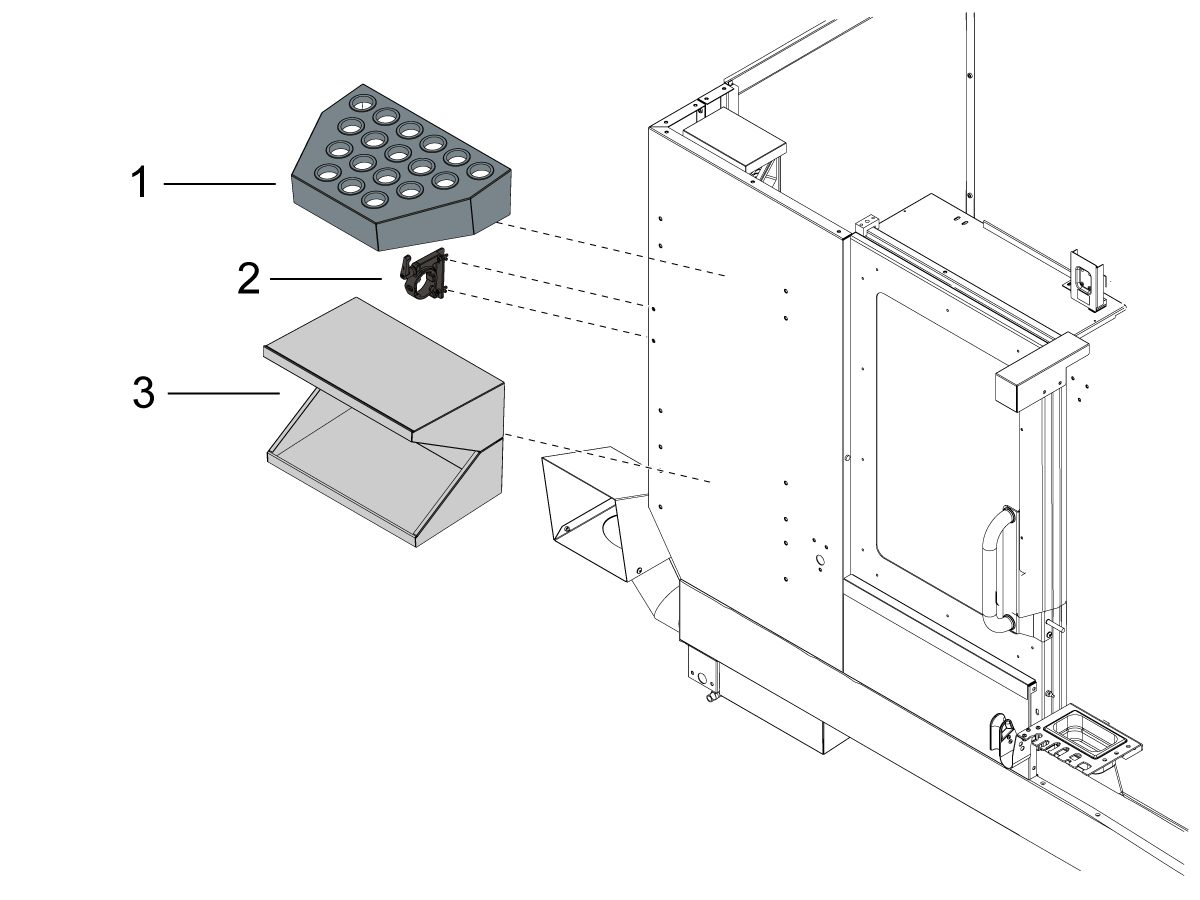
1

Rögzítse a szerszámtálcát [1] a gép burkolatának elülső részére. 

Rögzítse a szerszámbefogót [2] a szerszámtálca [1] alatt a gép burkolatának elülső részére.

Rögzítse a munkaasztalt [3] a szerszámbefogó [2] alatt a gép burkolatának elülső részére.

Coolant Hose Installation

1

Csatlakoztassa a kék hűtőközeg-tömlőt a szűrő bemenetről a hűtőközeg-szivattyú aljzatba [1].

Csatlakoztassa a hűtőközeg-szivattyút az kisnyomású hűtőközeg dugóhoz.[2]. 

Telepítse a hűtőközeg szintérzékelőjét. További információkért lásd: Hűtőközeg lebegő érzékelő telepítése. 

Hűtőközeg szintjét lebegtető érzékelő - NGC - Telepítés

Machine Operation

1

A próborsóműködés

Futtassa a O09221 orsó bejárató programot.

Ha szokatlan orsózajt tapasztal, akkor végezzen rezgéspróbát. Az orsó rezgéspróbájának elvégzéséről szóló útmutatót itt találja: 

Rezgéselemzés-Ethernet interfész
Rezgésanalízis – RS-232 felület

2

A hűtőközeg működésének tesztelése

Töltse fel a hűtőközeg-tartályt a szükséges mennyiségű hűtőközeggel a tartály feltöltéséhez.

Futtassa a hűtőközeget a  [COOLANT]  gomb megnyomásával a hordozható vezérlőn.

3

Tesztelje az ajtó zárak

Nyomja meg a [MDI]gombot. Írja be a következőt: S500 M3; Nyomja meg az [ENTER] gombot.

Ellenőrizze, hogy a készülék NINCS-E BEÁLLÍTÁSI ÜZEMMÓD-ban. Ellenőrizze a BILLENTYŰKAPCSOLÓT a vezérlő oldalán.

Az ajtónyílnál nyomja meg a [CIKLUS KEZDETE]. A gépnek jeleznie kellene, hogy zárja be az ajtót, és nyomja meg a [CIKLUSINDÍTÁS] gombot.

Az ajtó zárva, nyomja meg a [CIKLUS KEZDETE]. A reteszelő csapnak ki kell nyúlnia, és az orsó forogni kezd.

 fontos: Az orsó forgatásával tesztelje az ajtózárakat az ajtó kinyitásának megkísérlésével. Az orsó nem hagyja abba forog. 

4

Biztonsági funkciók tesztelése

Helyezze be a Beállítás/Futtatás zár kulcsát (#2007) az alsó kulcsnyílásba [2], és fordítsa el a nyitott helyzetbe.

Ellenőrizze, hogy a kulcs csak a zárolt pozícióból lehet-e eltávolítva.

Helyezze be a memóriazár kulcsát (#2341) a felső kulcsnyílásba [1], és fordítsa el a zárolt helyzetbe.

Ellenőrizze, hogy a kulcs eltávolítható-e mindkét pozícióból.

A zárolt pozícióban lévő Memóriamegzárógomb segítségével ellenőrizze, hogy a beállítások vagy a programok módosításai nem történtek-e meg.

Győződjön meg arról, hogy mindkét ablak lecsukódott-e. 

5

Forgácskihordó

Tesztelje a chip Auger (ha fel van szerelve).

Nyomja meg a [CHIP FWD] és a [CHIP REV] gombokat a vezérlőn.

6

WIPS kalibrálás NGC 

Ha a gép tartalmazza a WIPS opciót, akkor tekintse meg a következő hivatkozást a kalibrálási eljárással kapcsolatos utasításokért:

WIPS kalibrálás NGC

Mill Maintenance Schedule

Tartsa a Haas gépek futó csúcsteljesítményt elkerülve a nem tervezett leállás. A karbantartási program lehetővé teszi, hogy kezelje a menetrend helyett, hogy elkapják a korai meglepetéseket. A lenti hivatkozáson láthatja az ajánlott karbantartási időközöket.

Maró karbantartási ütemterv

3.3 Rögzítés

Recently Updated

Rögzítési utasítások


Introduction

This procedure will show you how to install the Drop-In expansion style anchors to a Haas CNC.

NOTE: If the machine was built before Jan 2020 or is a VS or HDC series machine, please refer to the epoxy style anchoring procedure (AD0212) click here.

For instructions on how to anchor the various components for the Haas Cobot kits refer to the Haas Cobot - Anchoring instruction page.

This procedure applies to the following Service Kits:

Mill
Model Part Number
DC-1 93-1001018
DC-2 93-1001019
DC-4 93-1001211
DT/DM-1, DT/DM-2 93-1000601
DT/DM-3 93-1001136
EC-400/VC-400

93-1000567

See Note Below

EC-500/50 93-1001145
EC-1600/UMC-1600H 93-1000535
EC-630 93-1000856
GM-1 93-1001115
GM-1XT 93-1001235
GM-2-3AX 93-1000574
GM-2-5AX 93-1000542
GR-510 93-1000574
GR-712 93-1000574
MM/SMM Reboot 93-1001016
UMC-350HD 93-1000780
UMC-400/SS 93-1001224
UMC-500/SS 93-1000379
UMC-750/SS (NON REBOOT) 93-1000380
UMC-750/SS (REBOOT)  93-1001324
UMC-1000/SS (REBOOT) 93-1001324
UMC-1250/SS 93-1000644
UMC-1500-DUO/SS-DUO 93-1000871
VF-1/2, VF-2TR, VF-2SS 93-1000534
VF-2YT, VF-2SSYT, VM-2 93-1000549
 VF-3/3SS, VF-4/4SS 93-1000550
VF-3YT/3YTSS, VF-3YT/50, VF-5/40, VF-5/40TR, VF-5/40XT, VF-5SS, VF-5/50, VF-5/50TR, VF-5/50XT, VM-3, VMT-750 93-1000548
VF-6/40, VF-6SS, VF-6/40TR, VF-7/40, VF-6/50, VF-6/50TR, VF-7/50, VM-6 (Base with 8 leveling feet) Built between January 2020 and September 6th 2023 93-1000547
VF-8/40, VF-9/40, VF-8/50, VF-9/50, VR-8, VR-9 (Base with 8 leveling feet) Built between January 2020 and October 6th 2023 93-1000546
VF-10/40, VF-12/40, VF-10/50, VF-12/50 (Base with 8 leveling feet) 93-1000545
VF-11/40, VF-11/50, VR-11 (Base with 8 leveling feet) 93-1000544
VF-6/6TR/6SS/7/10/12 both 40T & 50T and VM-6 (Base with 6 leveling feet) Built September 7th 2023 and later 93-1000999
VF-8/9/11/14 both 40T & 50T and VR-8/9/11/14 (Base with 6 leveling feet) Built October 7th 2023 and later 93-1001000
VS-3 93-1000870
Updated
Note: For EC-400 anchor kit 93-1000567 only. EC-400 Anchor Template 96-0286 only permits 7 of the 8 anchor locations to be utilized. The anchor spot under the front door is inaccessible due to improper enclosure spacing. This is corrected with EC-400 Anchor Template 96-0286A, which shifts the front anchor location to a more accessible spot. 
 
Pallet Pool/RPL
Model Part Number
UMC-500PP 93-3526
UMC-750PP (V1) See Note Below
UMC-750PP (V2) 93-3527
UMC-1000PP (V2) 93-3527
UMC-1250PP See Note Below
EC-400PP 93-3525
VF-2YTPP See Note Below
VF-4 PP See Note Below
Robot Pallet Loader See Note Below
Note: There is currently no 93-xxxx service kit for the following models:
  • (30-12644B + 96-0316A) UMC-750 Pallet Pool (V1)
  • (30-12644B + 96-0364) VF-2YT Pallet Pool
  • (30-12644B + 96-0383) VF-4 Pallet Pool
  • (30-12644B + 96-0388) Robot Pallet Loader

You would need to order individual parts,  please contact your Local Haas Factory Outlet for availability.

Lathe
Model Part Number
ST-10/10Y/15/15Y 93-1000378
ST-10L/10LY/15L/15LY 93-1000855
ST-20/25/20Y/25Y 93-1000552
ST-20L/20LY/25L/25LY/28L/28LY 93-1001005
ST-30/35/30Y/35Y, DS-30Y (REBOOT ONLY) 93-1000541
ST-30L/35L/LY 93-1001079
ST-40 93-1000540
ST-40/40Y (Reboot) 93-1000819
ST-40L 93-1000539
ST-40L (Reboot) 93-1000820
ST-40S/45S/SY  93-1001012
ST-50/55 93-1000538
TL-1 93-1000537
TL-2 93-1000536
Extended Liner System
ST-10/10L/10Y/10LY 93-1000844
93-1000845

Tools required:

  • Paint markers
  • Painters Tape
  • Pipe cleaner brush
  • 5 lb. Sledge Hammer
  • SDS Plus Hammer Drill
    Note:  The SDS-Plus Hammer drill should be rated for 1" bit.

Video Instructions

Anchor Template Placement

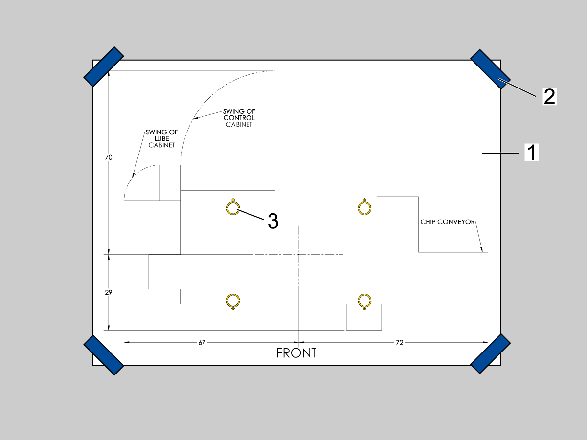
  1. Unroll machine anchoring template [1].
  2. Use centerlines and provided reference sheet dimensions, measure distances to nearest allowable obstructions.
  3. Once position is established, taped the corners [2] of the anchoring template to the foundation.  Keep the template as flat as possible.
  4. Spray paint the foundation in the cutout areas of the template [3].
  5. Let the paint dry for 5-10 minutes.
  6. Remove the anchoring template [1].

Drill Holes and Set the Anchors

Use the provided SDS-Plus Style drill for the following steps:

  • Drill specified number of 5/8" holes at depth 2.00 - 2.25" each.  
    • Drill bit should be perpendicular to foundation.
  • Clean the holes with pipe cleaner.
  • Use compressed air and a vacuum to clear holes.
  • Repeat for the number of leveling pads.
  • Cover the holes with tape to protect from unwanted debris while the other holes are drilled.
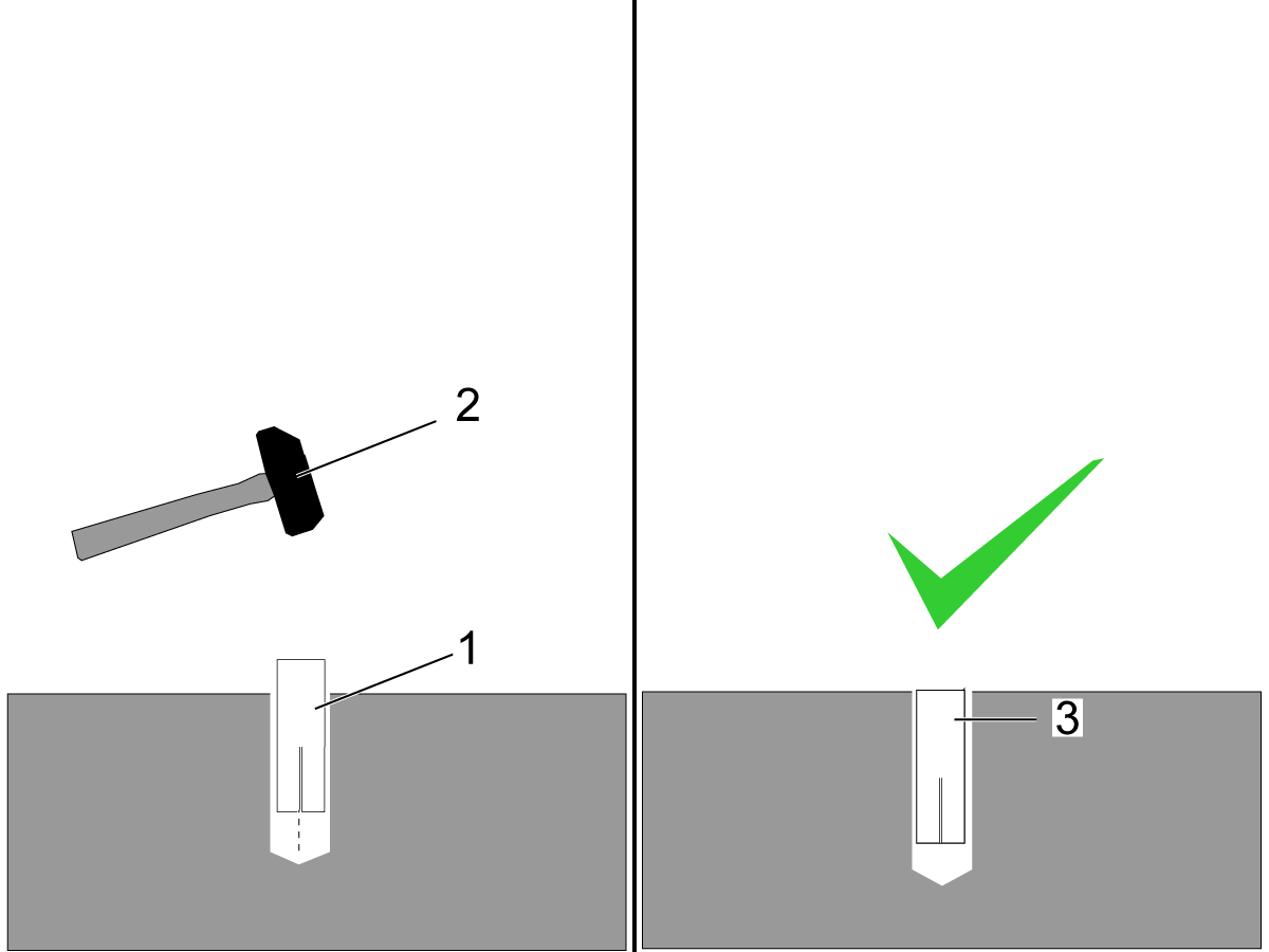
  • Using the hammer [2] set the drop-in anchor [1] flush with the concrete [3].

    Note:  Do not use the set tool to drive the anchor.  
  • Use the provided setting tool [1] and hammer [2], to seat the anchor in the concrete.
  • Make sure that the anchors are seated flush [3], use the setting tool as a gauge.
    Note:  Be careful not to overdrive the anchor [4] to far inside the hole.

Machine Placement

  1. Once the anchors are set, place the leveling pads on the spray painted cross-hairs.
  2. Place the machine on the leveling pads.
  3. Set the machine height.
  4. Level the machine
  5. Tighten down the machine locknuts.

Anchoring Strap Installation

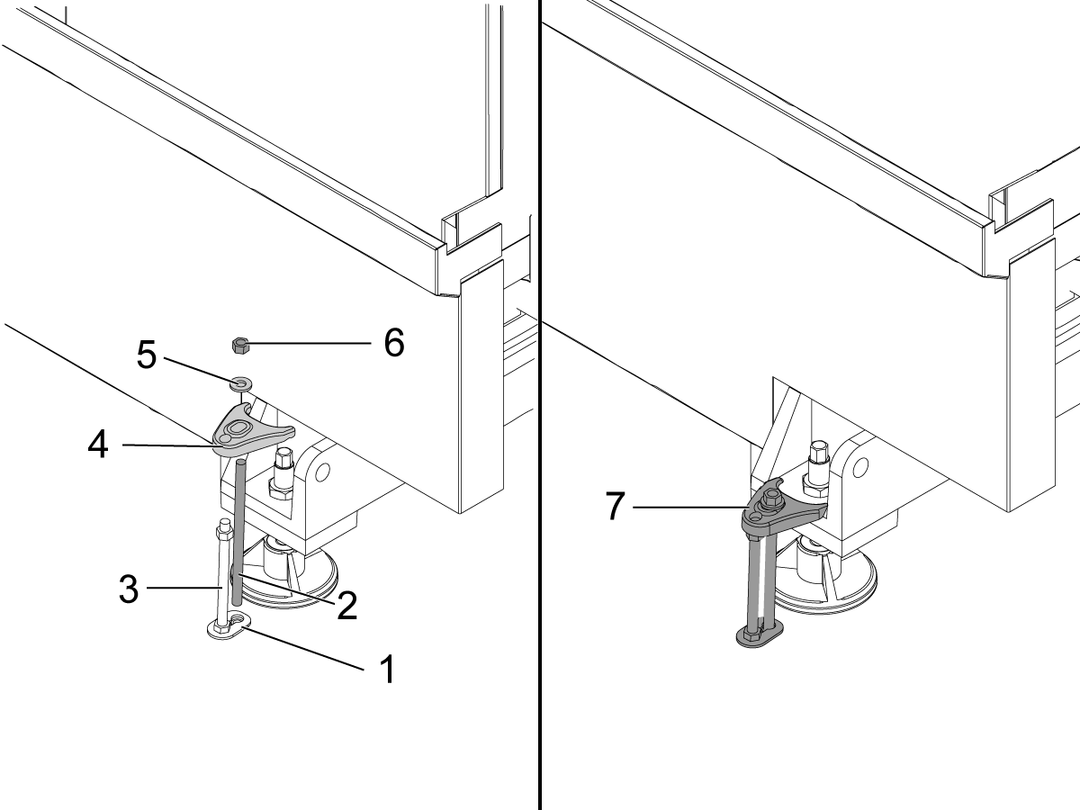
  1. Place the thrust plate flush [1] with the foundation.
  2. Thread stud [2] into the anchor location using two lock nuts.
  3. Place 1/2-13 hex nut on the 1/2-13 hex bolt [3] on top of the thrust plate.
  4. Place the anchoring strap [4].
  5. Place the washer [5] on the threaded rod.
  6. Thread the 1/2-13 hex nut [6] into the threaded rod.
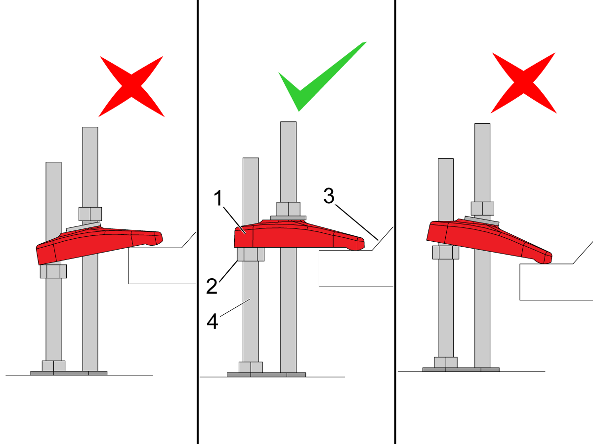
  7. Be sure the anchoring strap [7] remains parallel to the clamped casting surface.
  8. Torque 1/2-13 hex nut to 25ft-lbs (34 nm).

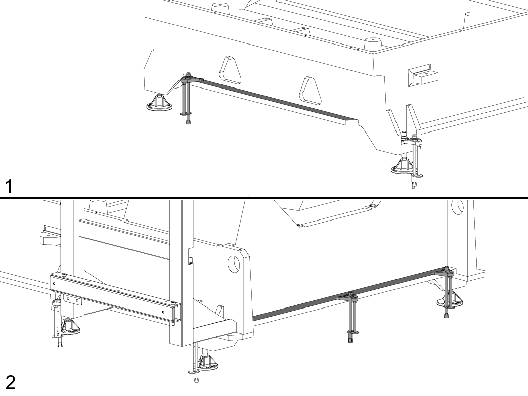
Make sure that the anchor strap [1] is level on the hex nut [2] and the machine base [3].

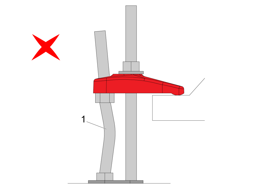
NOTE: Make sure the threaded stud [4] is perpendicular to the floor and not bent. 

Make sure the threaded stud welded to the base is not bent as shown in the image [1].

If this occurs make sure that the anchor holes are drilled straight and re-drill them if necessary. 

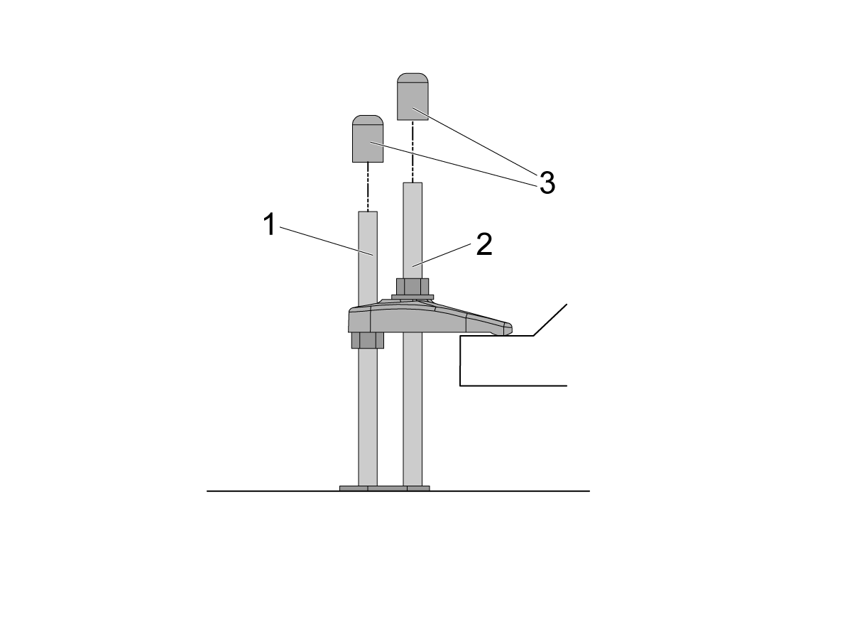
If there is clearance on the anchor [1] and stud [2] place the end caps [3] on the ends as shown in the image. Place these caps on all all anchors.

NOTE: The UMC-1250/SS does not have the anchoring fingers on the base foot. The indicated holes on the anchoring layout will have them anchoring down the base flange as shown in the image. Image [1] is the front of the machine, while image [2] is the back of the machine. 

Sheet Metal Anchor Bracket Installation

These instructions are used for installing sheet metal anchor brackets or fence posts for APLs or Haas Robot Packages.

Note: There is no anchor template included with these assemblies. The brackets and fence post anchor holes are used to create the anchor hole locations. The locations are dimensioned in the layouts of the install instructions.

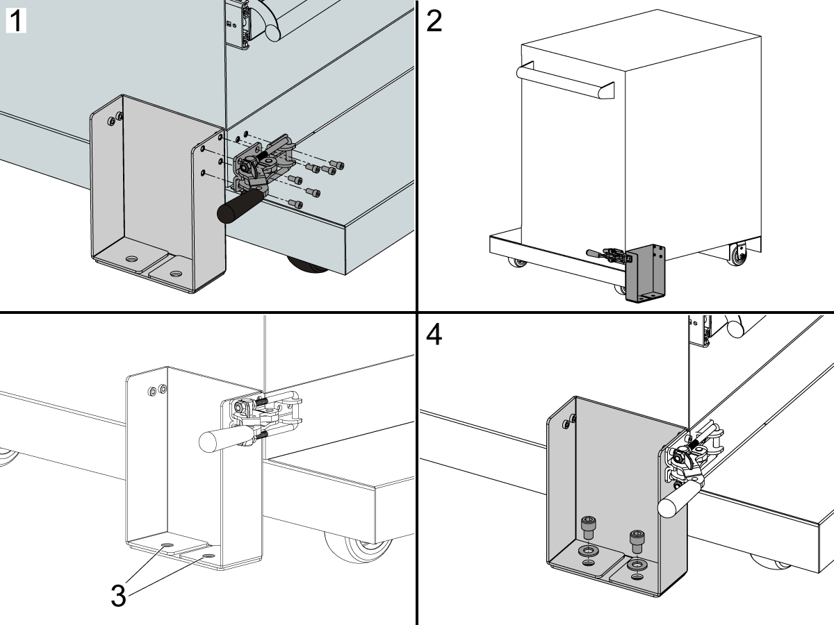
1. Install the Latch Toggle Clamp to the front of the Robot Drawer Cart and Sheet Metal Anchor Bracket.

2. Install the Latch Toggle Clamp to the rear of the Robot Drawer Cart and Sheet Metal Anchor Bracket.

3. The Sheet Metal Anchor Bracket or Fence Post holes are used to mark the drop in anchor hole locations.

4. Install the anchor hardware after the anchors are installed using the Drill Holes and Set the Anchors instructions above.

Recently Viewed Items

You Have No Recently Viewed Items Yet

Visszajelzés
Haas Logo

A Haas szállította termékek árszabása

Ez az ár tartalmazza a szállítás költségeit, valamint az export- és importtevékenységekhez kapcsolódó vámterheket, a biztosítást és minden olyan további felmerülő költséget, amely egy franciaországi helyszínre történő kiszállítást terhel, melybe Ön mint vevő beleegyezett. A Haas CNC termékek szállítása nem járhat további kötelező költségekkel.

KÖVESSE A LEGÚJABB HAAS TIPPEKET ÉS TECHNOLÓGIÁT…

Regisztráljon most!   

A HAAS TOOLING A KÖVETKEZŐKET FOGADJA EL:

  • Szerviz és támogatás
  • Tulajdonosok
  • Szervizkérés
  • Kezelési utasítások
  • Haas alkatrészek
  • Forgóasztal javításkérés
  • Útmutatók előtelepítése
  • Szerszámok vásárlása
  • Új Haas kiépítés és ár
  • Elérhető készlet
  • Haas árlista
  • CNCA finanszírozás
  • A Haas cégről
  • Akadálymentesítési nyilatkozat
  • DNSH nyilatkozat
  • Exportmegfelelés
  • Álláslehetőségek
  • Tanúsítványok és biztonság
  • Lépjen velünk kapcsolatba
  • Történet
  • Szerződési feltételek
  • Haas Tooling - Szerződési feltételek
  • Adatvédelem
  • Jótállás
  • Haas közösség
  • Haas tanúsítási program
  • Haas Motorsports
  • Gene Haas Foundation
  • Haas technikai oktató közösség
  • Események
  • Csatlakozzon a beszélgetéshez
  • Facebook
  • X
  • Flickr
  • YouTube
  • LinkedIn
  • Instagram
  • TikTok
© 2026 Haas Automation, Inc. - CNC szerszámgépek

This site is protected by reCAPTCHA and the Google Privacy Policy and Terms of Service apply.

2800 Sturgis Rd., Oxnard, CA 93030 / Toll Free: 800-331-6746
Phone: 805-278-1800 / Fax: 805-278-2255