My Haas Välkommen
!
Haas Tooling MyHaas/HaasConnect Logga in Registrera Haas Tooling MyHaas/HaasConnect Logga ut Välkommen Mina maskiner Senaste aktivitet Mina offerter Mitt konto Mina användare Logga ut
Hitta din återförsäljare
  1. Välj språk
    1. English
    2. Deutsch
    3. Español - ES
    4. Español - MX
    5. Français
    6. Italiano
    7. Português
    8. Český
    9. Dansk
    10. Nederlands
    11. Magyar
    12. Polski
    13. Svenska
    14. Türkçe
    15. 中文
    16. Suomi
    17. Norsk
    18. الإنجليزية
    19. български
    20. Hrvatski
    21. Ελληνικά
    22. Română
    23. Slovenský
    24. Slovenščina
    25. 한국어
    26. 日本語
    27. Українська
  • maskiner Main Menu
    • VMT-serien
      VMT-serien
      VMT-serien View All
      • VMT-serien
      • VF-serien
      • UMC-serien
      • VR-serien
      • Prismatisk VP-5
      • VMC med palettväxlare
      • Minimill
      • VM-serien
      • Höghastighetsborrmaskiner
      • Drill/Tap/Mill-serien
      • Toolroom-serien
      • Pocket Mill
      • Compact Mill
      • Portalfräsar
      • SR skivmatningsbord
      • VS-serien
      • Fräsar med dubbla pelare
    • Fleraxlade lösningar
      Fleraxlade lösningar
      Fleraxlade lösningar View All
      • Fleraxlade lösningar
      • Svarvar med Y-axel
      • 5-axlig fräs
    • Svarvar
      Svarvar
      Svarvar View All
      • Svarvar
      • ST-serien
      • Dubbla spindlar
      • Box Way-serien
      • Toolroom-svarvar
      • CL-serien
      • Ficksvarv
      • Haas Stångmagasin
    • Horisontalfräsar
      Horisontalfräsar
      Horisontalfräsar View All
      • Horisontalfräsar
      • Horisontella fleroperationsmaskiner/ 50-kona
      • Horisontella fleroperationsmaskiner/ 40-kona
    • Rundmatningsbord och indexerare
      Rundmatningsbord och indexerare
      Rundmatningsbord och indexerare View All
      • Rundmatningsbord och indexerare
      • Rundmatningsbord
      • Indexerare
      • 5-axliga rundmatande produkter
      • Extra stora rundmatningsbord
    • Automatiseringssystem
      Automatiseringssystem
      Automatiseringssystem View All
      • Automatiseringssystem
      • Automatisering för fräsar
      • Automatiseringslösning för svarv
      • Automatisk laddare av delar
      • Automatiseringsmodeller
    • Skrivbordsmaskiner
      Skrivbordsmaskiner
      Skrivbordsmaskiner View All
      • Skrivbordsmaskiner
      • Desktop Mill
      • Desktop Lathe
      • Styrsimulator, standard
      • Styrsimulator, Premium
    • Verkstadsutrustning
      Verkstadsutrustning
      Verkstadsutrustning View All
      • Verkstadsutrustning
      • Bordsfräs
      • Haas manuell svarv
      • Haas-sågar
    • Tillverkningsmaskiner
      Tillverkningsmaskiner
      Tillverkningsmaskiner View All
      • Tillverkningsmaskiner
      • Laserskärmaskiner
      • CNC-pressbromsar
    • SNABBLÄNKAR Specialserie  Specialserie 
      EU-SERIEN EU-SERIEN BYGG-OCH-SE PRIS | PRISLISTA BYGG-OCH-SE PRIS | PRISLISTA Maskiner i lager Maskiner i lager NYHETER NYHETER DIN FÖRSTA CNC-MASKIN DIN FÖRSTA CNC-MASKIN
      KÖPA VERKTYG
      • Bygg och prissätt en Haas
      • Prislista
      • Tillgänglig inventorie
      • CNCA-finansiering
      VILL DU KOMMA I KONTAKT MED OSS?

      Din Haas-leverantör (HFO) kan besvara alla dina frågor och diskutera vilka lösningar som är bäst för dig.

      CONTACT YOUR DISTRIBUTOR >
  • Alternativ Main Menu
    • The Haas Control Värdetillvalspaket
      Värdetillvalspaket
      Värdetillvalspaket View All
      • Värdetillvalspaket
    • Product Image Spindlar
      Spindlar
      Spindlar View All
      • Spindlar
    • Product Image Verktygsväxlare
      Verktygsväxlare
      Verktygsväxlare View All
      • Verktygsväxlare
    • Product Image 4:e | 5:e-axlade
      4:e | 5:e-axlade
      4:e | 5:e-axlade View All
      • 4:e | 5:e-axlade
    • Product Image Revolvrar och roterande verktyg
      Revolvrar och roterande verktyg
      Revolvrar och roterande verktyg View All
      • Revolvrar och roterande verktyg
    • Product Image Sondering
      Sondering
      Sondering View All
      • Sondering
    • Haas – Hantering av spån och kylmedel Hantering av spån och kylmedel
      Hantering av spån och kylmedel
      Hantering av spån och kylmedel View All
      • Hantering av spån och kylmedel
    • Haas styrsystem Haas styrsystem
      Haas styrsystem
      Haas styrsystem View All
      • Haas styrsystem
    • Product Image Produktalternativ
      Produktalternativ
      Produktalternativ View All
      • Produktalternativ
    • Product Image Verktyg och fixturtillbehör
      Verktyg och fixturtillbehör
      Verktyg och fixturtillbehör View All
      • Verktyg och fixturtillbehör
    • Product Image Uppspänningsanordning
      Uppspänningsanordning
      Uppspänningsanordning View All
      • Uppspänningsanordning
    • Product Image 5-axliga lösningar
      5-axliga lösningar
      5-axliga lösningar View All
      • 5-axliga lösningar
      • 5 Easy Steps to 5-Axis
    • Product Image Automatisering
      Automatisering
      Automatisering View All
      • Automatisering
    • SNABBLÄNKAR Specialserie  Specialserie 
      EU-SERIEN EU-SERIEN BYGG-OCH-SE PRIS | PRISLISTA BYGG-OCH-SE PRIS | PRISLISTA Maskiner i lager Maskiner i lager NYHETER NYHETER DIN FÖRSTA CNC-MASKIN DIN FÖRSTA CNC-MASKIN
      KÖPA VERKTYG
      • Bygg och prissätt en Haas
      • Prislista
      • Tillgänglig inventorie
      • CNCA-finansiering
      VILL DU KOMMA I KONTAKT MED OSS?

      Din Haas-leverantör (HFO) kan besvara alla dina frågor och diskutera vilka lösningar som är bäst för dig.

      CONTACT YOUR DISTRIBUTOR >
  • Why Haas Main Menu
      Upptäck skillnaden med Haas
    • Varför Haas
    • MyHaas
    • Utbildningsgrupp
    • Industri 4.0
    • Haas-certifiering
    • Kundreferenser
  • Service Main Menu
      Välkommen till Haas Service
      SERVICEHEMSIDA Bruksanvisningar Så här går det till Felsökningsguider Förebyggande underhåll Haas reservdelar Haas-verktyg Video
  • Video Main Menu
My Haas Välkommen
!
Haas Tooling MyHaas/HaasConnect Logga in Registrera Haas Tooling MyHaas/HaasConnect Logga ut Välkommen Mina maskiner Senaste aktivitet Mina offerter Mitt konto Mina användare Logga ut
Hitta din återförsäljare
  1. Välj språk
    1. English
    2. Deutsch
    3. Español - ES
    4. Español - MX
    5. Français
    6. Italiano
    7. Português
    8. Český
    9. Dansk
    10. Nederlands
    11. Magyar
    12. Polski
    13. Svenska
    14. Türkçe
    15. 中文
    16. Suomi
    17. Norsk
    18. الإنجليزية
    19. български
    20. Hrvatski
    21. Ελληνικά
    22. Română
    23. Slovenský
    24. Slovenščina
    25. 한국어
    26. 日本語
    27. Українська
×

Sökresultat

Web Pages

Images

    • <
    • 1
    • >

3 - MM / SMM - Installation

MiniMill/Super Minimill – Interaktiv – Servicemanual


  • 0 - MM / SMM - Innehållsförteckning
  • 1 - MM/SMM – Introduktion
  • 2 - MM/SMM – Specifikationer
  • 3 - MM/SMM – Installation
  • 4 - MM/SMM – Paraplyverktygsväxlare
  • 5 - MM/SMM – SMTC
  • 6 - MM/SMM – Axelrörelse
  • 7 - MM/SMM – Spindel
  • 8 - SM/SMM – Spindelmotor
  • 9 - MM/SMM – Smörjsystem
  • 10 - MM/SMM – Elektrisk styrning
  • 11 - MM/SMM - Spåntransport och kylmedel
  • 12 - MM/SMM – Uppspänningsanordning
  • 13 - MM/SMM – Underhåll
  • 14 - MM/SMM – Autodörr och autofönster
  • 15 - MM/SMM – Robot och automatisering
  • 16 - MM/SMM – Hölje

Go To :

  • 3.1 MM/SMM Installation
  • 3.2 Reboot MM/SMM Installation
  • 3.3 Förankring

3.1 MM/SMM – Installation

Recently Updated

Mini Mill/Super Mini Mill – Installation


Introduction

Den här proceduren beskriver hur du installerar en Minimill/2/EDU eller Super Minimill/2. För att installera en omstart av Minimill eller Super Minimill, läs mer i proceduren Minimill/Super Minimill – Installation. 

För att avgöra vilken typ av Minimill-version du har, se referensdokumentet Minimill/Super Minimill – Maskinversion – Identifiering .

Verktyg som krävs:

  • 3/4" Socket
  • 5/32", 1/4", 3/8" Hex-Bitarsuttag
  • Ratchet
  • 3/4", 1.5" Skiftnyckel
  • Måttband
  • 0,0005" eller 1 micron test indikator och magnetisk bas
  • T-2181 SERVICE verktyg, UTJÄMNINGS verktyg eller precisions Maskinistisk nivå, 0,0005" Division

Leveling Screws Hardware

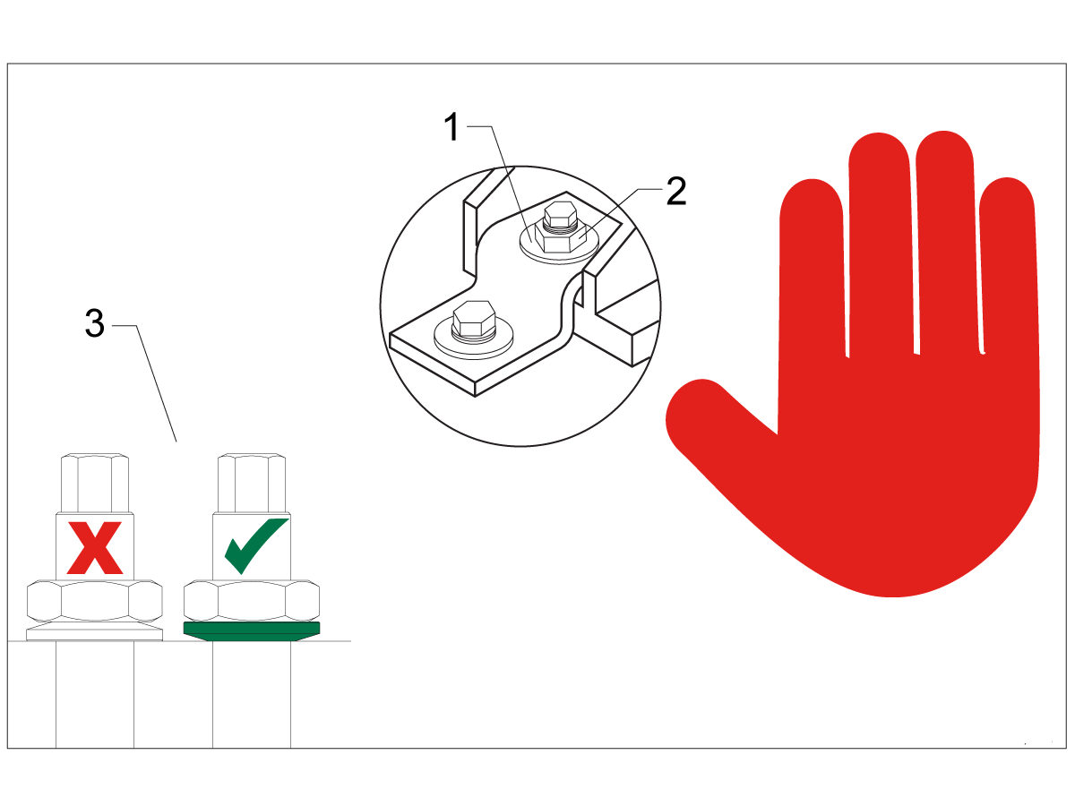
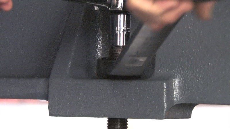
Note: The washers [1] and nuts [2] are installed during shipping and should be saved for installation and not be discarded.

Note: The washer orientation [3] is important.  The conical part of the washer should be against the casting,  see illustration.

Remove Rust Inhibitor

To safely and effectively remove rust inhibitor from way covers and other non-painted surfaces:

Initial Scraping

  • Use a plastic scraper to remove the bulk of the rust inhibitor.
  • Avoid using metal tools to prevent scratching or damaging the surface.

 Important: Do not use scotch-brite or metal scrapers, these will scratch the way covers.

Chemical Cleaning

  • Spray the affected areas with a heavy-duty citrus cleaner or Simple Green.
  • Ensure full coverage of all non-painted surfaces coated with rust inhibitor.

Soak Time

  • Allow the cleaner to soak for several minutes to loosen remaining residue.

Wipe Down

  • Use a clean shop towel to thoroughly wipe off the softened rust inhibitor.

Rust Proofing

  • Apply mineral spirits or WD-40 to all exposed metal surfaces to prevent future rust formation.

Important: Always wear gloves and eye protection when handling chemical cleaners. Dispose of used towels and cleaning agents according to local environmental regulations.

 Important: To avoid any contamination of the way cover seals with the sticky residue. Do not move any of the axes until all the rust inhibitor has been removed.

Rust Inhibitor - Safety Data Sheet (SDS)

Air Connection

Electrical Installation

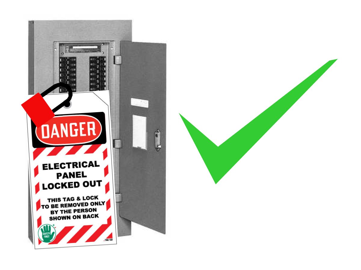
 DANGER: Working with the electrical services required for CNC machines is extremely hazardous and can result in serious injury or death.

Before connecting line wires to the CNC:

  • Turn off all power to the machine at the source.
  • Perform a Lockout-Tagout (LOTO) procedure to ensure the power remains off during service.
  • Verify that power has been disconnected by using an AC voltage detector on all incoming lines.

If you are uncertain about how to safely disconnect power or perform LOTO procedures:

  • Do not proceed.
  • Contact qualified personnel or obtain appropriate assistance before continuing.

Failure to follow these precautions may result in electrical shock, equipment damage, or fatal injury.

1

Initial Control Inspection

Danger: At this point, there should be no electrical connection to the machine. Electrical panel must be closed and secured. When main switch is on, there is HIGH VOLTAGE throughout the electrical panel (including the circuit boards and logic circuits) and some components operate at high temperatures. Therefore, exercise extreme caution when working in the panel.

  • Set the main breaker switch at the upper right of the electrical panel on the back of the machine to OFF.
  • Using a screwdriver, unlock the two latches on the panel door, unlock the cabinet with the key and open the door.
  • Take sufficient time to check all the components and connectors associated with the circuit boards. Look for any cables that have become disconnected, look for any signs damage and loose parts in the bottom of the panel box. If there are any signs that the machine was mishandled, call the factory before proceeding.

2

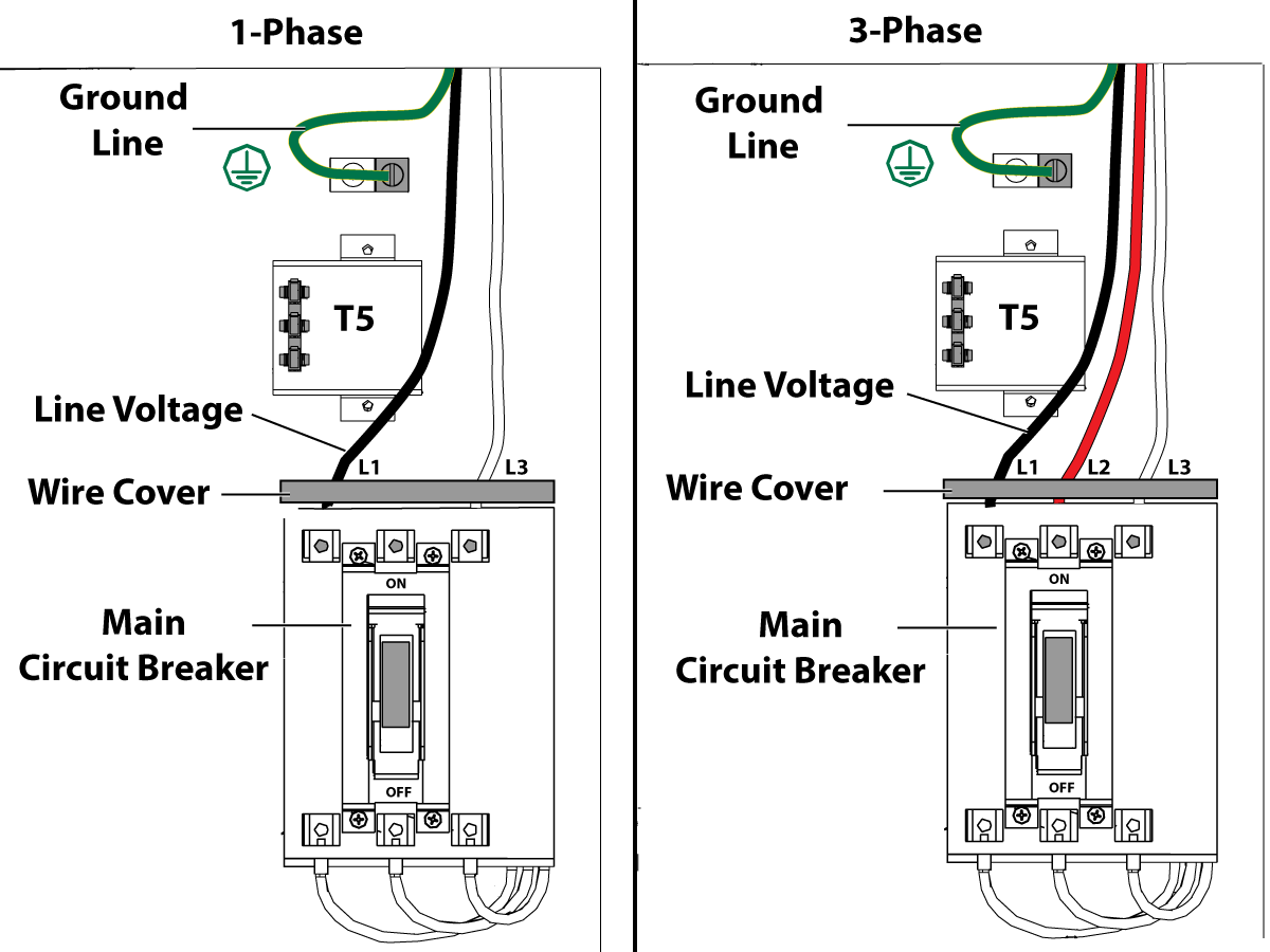
1-Phase Machines: Insert each power lead into the wire cover.  Connect the two power leads to L1 and L3 terminals on top of the main circuit breaker.

3-Phase Machines: Insert each power lead into the wire cover.  Connect the three power leads to L1, L2 and L3 terminals on top of the main circuit breaker.

Connect the separate ground line to the ground bus to the left of the terminals.

For 3-phase machines, check to see what type of power configuration is supplying the machine. Take voltage measurements of each power lead to ground line. Then refer to RD0084 - Input Power Configurations to determine which power lead should be connected to the L1 terminal based of the voltage readings and power configuration.

Refer to Haas Main Circuit Breaker - Torque Specifications for what value to torque the circuit breaker power leads.

 Note: Make sure that the leads actually go into the terminal-block clamps . (A poor connection will cause the machine to run intermittently or have other problems, such as servo overloads.) To check, simply pull on the wires after the screws are tightened.

3

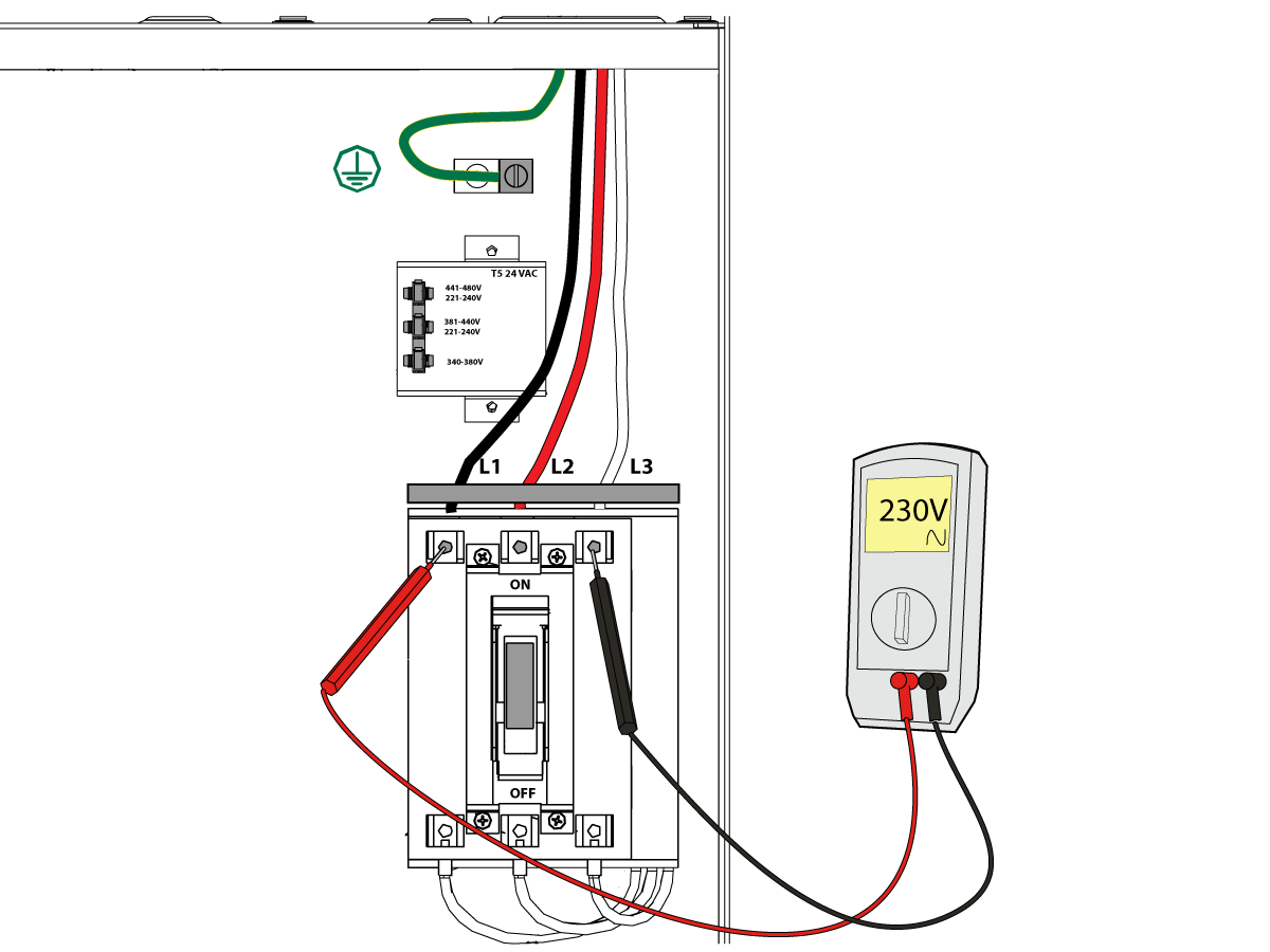
After the line voltage is connected to the machine, make sure that main circuit breaker (at top-right of rear cabinet) is OFF . Remove the Lockout / Tagout and Turn ON the power at the source. Using a digital voltmeter and appropriate safety procedures: 

1-Phase Machines: Measure the AC voltage across L1 & L3 at the main circuit breaker.  The AC voltage must be between 220 - 250 volts .
Note: Lower or higher than this voltage can generate low/high voltage alarms.

3-Phase Machines : Measure the AC voltage between all three pair phases at the main circuit breaker. 

The AC voltage must be between 195 and 260 volts (360 and 480 volts for high voltage option).

SMinimill - Reboot: The AC voltage must be between 198 and 242 volts for machines without a high voltage transformer.  Refer to the Minimill/SMinimill - Identification document.

 Note: Wide voltage fluctuations are common in many industrial areas; minimum and maximum voltage supplied to a machine while it is in operation must be known. U.S. National Electrical Code specifies that machines should operate with a variation of +5% to -5% around an average supply voltage. If problems with line voltage occur, or low line voltage is suspected, an external transformer may be used. If you suspect voltage problems, voltage should be checked every hour or two during a typical day to be sure it does not fluctuate more than +5% or -5% from an average.

4

Important: With the main circuit breaker turned OFF.

Check the transformer taps at the bottom-right corner of the rear cabinet.

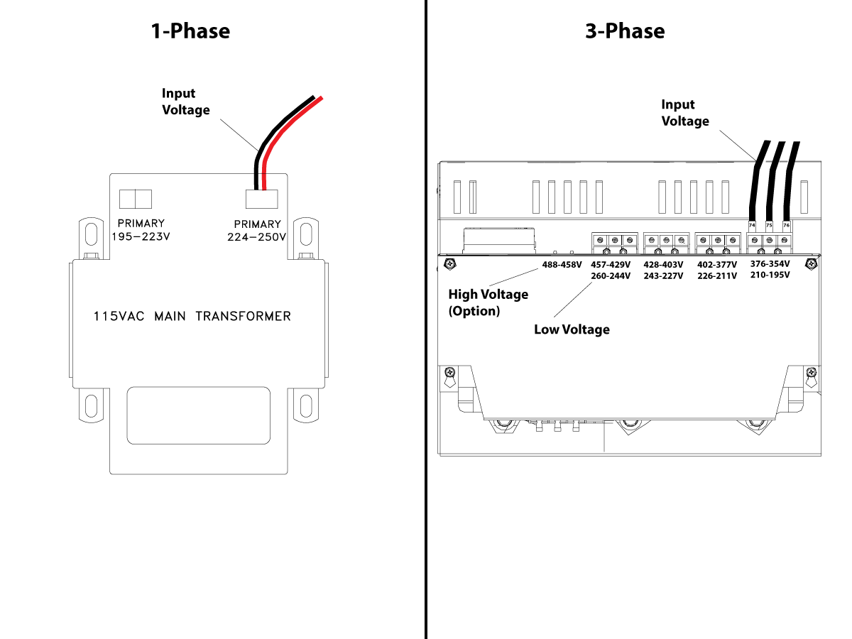
1-Phase Machines: The input voltage cable must be moved to the connector which corresponds to the average voltage measured in the above step.

3-Phase Machines:  The input voltage cables labeled 74, 75, and 76 must be moved to the terminal block triple which corresponds to the average voltage measured in the above step.

5

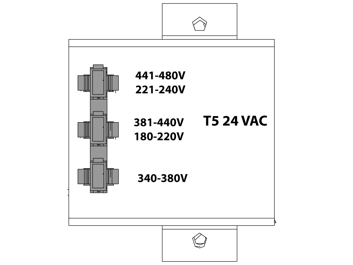
Transformer T5 supplies 24VAC used to power the main contactor. There are two versions of this transformer for use on a 240 and 400V machines. The 240V transformer has two input connectors located about two inches from the transformer, which allow it to be connected to either 180-220V or 221-240V.

Users that have 220V-240V RMS input power should use the connector labeled 221-240V, while users with 190-220V input power should use the connector labeled 180-220V. Failure to use the correct input connector will result in either overheating of the main contactor or failure to reliably engage the main contactor.

The 480V (option) T5 transformer has three input connectors, labeled 340-380V, 381-440V and 441-480V.

Users with 340-380V 50/60Hz power should use the 340-380V connector while users with 380V-440V 50/60Hz power should use the 381-440V connector.

Important: Set the main circuit breaker to ON. Check for evidence of problems, such as the smell of overheating components or smoke. If such problems are indicated, immediately set the main circuit breaker to OFF and call the factory before proceeding.

After the power is on, measure the voltage across the bottom terminals on the main circuit breaker. It should be the same as the measurements where the input power connects to the main breaker. If there are any problems, check the wiring.

6

Apply power to the control by pressing the Power-On switch on the front panel.

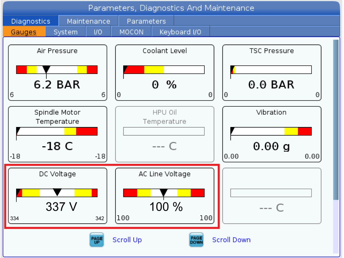
Check the DC Voltage and AC Line Voltage gauges in Diagnostics. The DC Voltage gauge must read between 310 - 360V. The AC Line Voltage must be between 90 and 105 percent. If the voltage is outside these limits, turn off the power and recheck steps 2 and 3. If the voltage is still outside these limits, call the factory.

7

Electrical power must be phased properly to avoid damage to your equipment. The Power Supply Assembly PC board incorporates a "Phase Detect" circuit with neon indicators. When the orange neon is lit (NE5), the phasing is incorrect. If the green neon is lit (NE6), the phasing is correct. If both neon indicators are lit, you have a loose wire; check the connections. Adjust phasing by setting the source power to off and then swapping L1 and L2 of the incoming power lines at the main circuit breaker.

Danger: ALL POWER TO CNC MUST BE TURNED OFF LOCKOUT-TAGOUT AT THE SOURCE PRIOR TO ADJUSTING PHASING. ALWAYS DOUBLE CHECK THE INCOMING LINES WITH AN AC VOLTAGE DETECTOR.

Turn off the power and set the main circuit breaker to OFF. Close the door, lock the latches, and turn the power back on.

Remove the key from the control cabinet and give it to the shop manager.

8

Activation

When the machine is properly placed and connected to both air and electrical power, it is ready for final installation (removing shipping blocks, leveling, spindle sweep, etc.) and software activation. The HFO service technician does this. Contact the local HFO to schedule the work.

IMPORTANT:  Machines equipped with motion sensors must be rough‑leveled before attempting to arm the motion sensor.  For detailed instructions, refer to Service Notification - SA0007.  Access to this document is restricted to Haas Factory Outlet personnel.

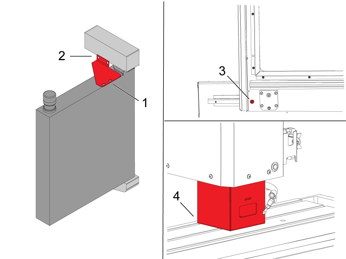
Shipping Brackets Removal

1

Ta bort pendel fästet.

2

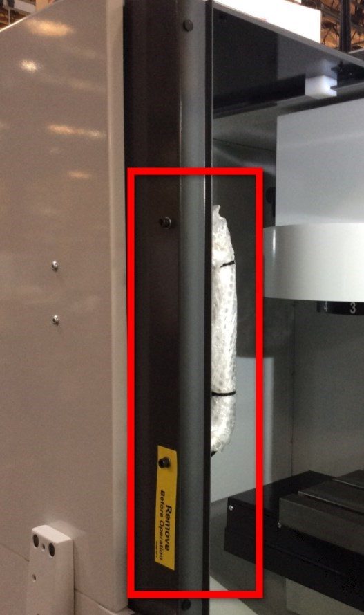
Ta bort operatörsdörrens sändnings fäste.

3

Sätt tillbaka dörrhandtaget på utsidan av operatörsdörren.

4

Tryck [POWER ON] och följ instruktionerna som visas på skärmen.

Tryck på knappen [HAND JOG] Och [Z+] Knappar. Jogga Z-axeln uppåt.

Ta bort 40T-spindelns leveransfäste.

Machine Leveling

1

Noll returnera varje axel i taget eller tryck på. Gå igenom utjämningsprocessen.
Upprepa dessa steg för att uppnå korrekt maskinnivå.

2

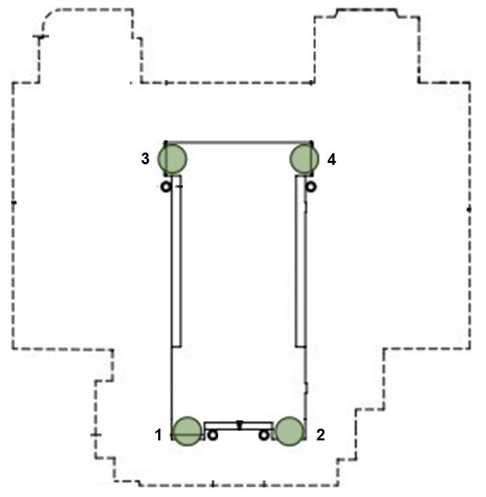
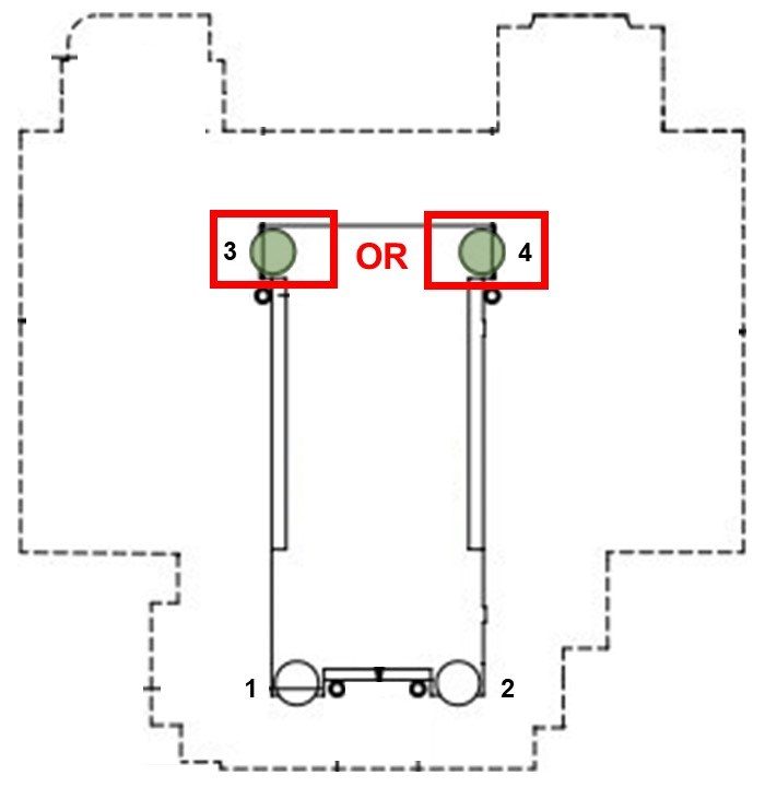
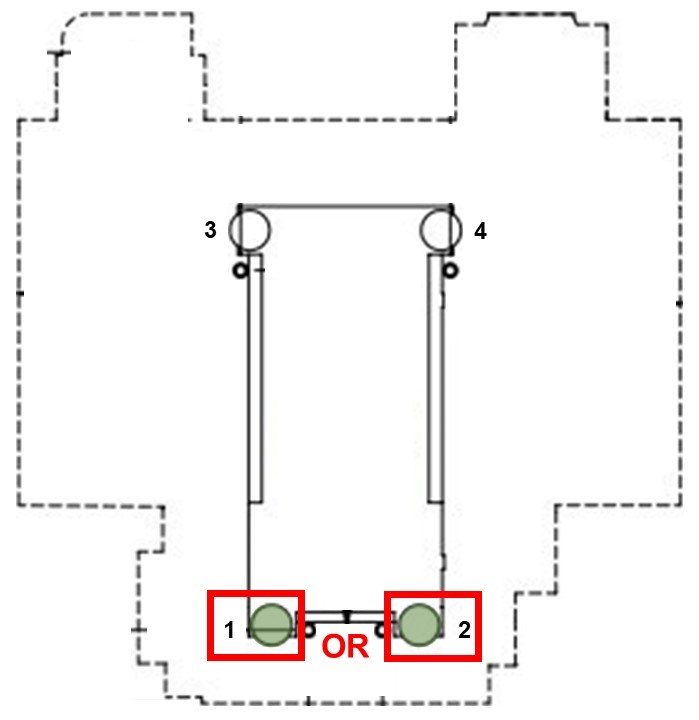
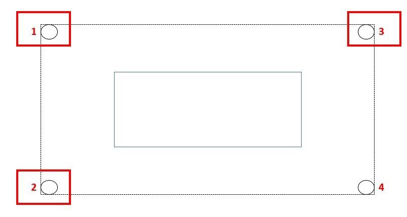
Ställ in maskinens höjd med de fyra hörn Utjämnings bultarna [1, 2, 3, 4] till 3" +/-0,5" (75 mm +/- 10 mm) ovanför golvet. Vrid varje skruv så att de har lika spänning.

JOG X-axeln och Y-axeln till mitten av deras resa, centrering bordet.

Anm.: Bilden visar layouten för DM-2, men samma process gäller för alla DM, DT, Mini Mill och Super Mini Mill med fyra nivelleringsbultar. Om din maskin har sex eller fler nivelleringsbultar, vänligen se:

VMC-utjämning

3

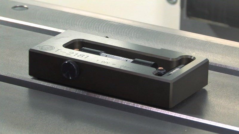
Rengör bordsytan och utjämningsverktyget (T-2181) och kontrollera kalibreringen av utjämningsverktyget innan du fortsätter.

Placera nivån i mitten av lastpallen parallellt med X-axeln.  Använd en t-plats för justering.

Anteckna positionen för bubblan.

Ompositionera nivån genom att vrida den 180 grader. Bubblan ska visa samma läsning som tidigare.

Om avläsningarna skiljer sig från mer än en division, returnera nivån till Haas för justering och Använd den inte för att jämna till maskinen.

4

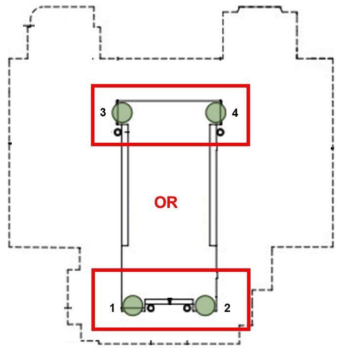
Justera hörn Utjämnings bultar [1, 2] eller [3, 4] tills bubblan parallellt med Y-axeln är centrerad.

Detta jämnar maskinens framsida till baksidan.

Höj alltid maskinens undersida för att bibehålla clearance för kylvätskebehållaren (om sådan finns) och justera de två utjämningbultarna på den sidan lika mycket.

5

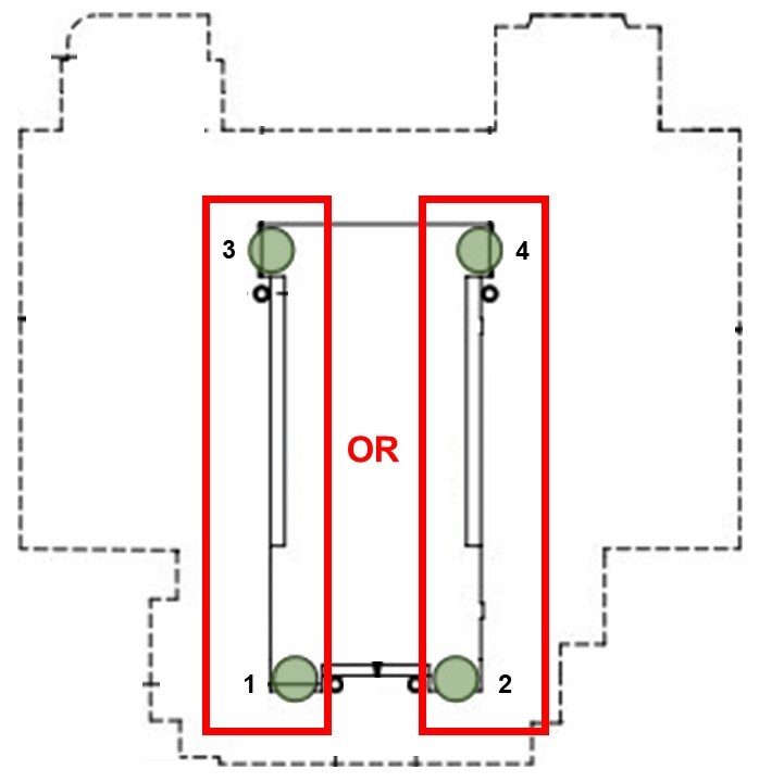
Justera hörn Utjämnings bultar [1, 3] eller [2, 4] tills bubblan parallellt med X-axeln är centrerad.

Detta jämnar maskinen från vänster till höger.

Återigen, Höj den nedre sidan av maskinen och justera de två utjämningbultarna på den sidan ett lika mycket.

6

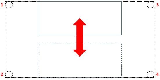
Håll nivån i samma position och jogga Y-axeln för att få bordet på framsidan av maskinen.

Anteckna positionen för bubblan.

JOG Y-axeln över hela sin resa, stoppa vid kolonnen. Se vilket bakre hörn av maskinen som är lägst, vilket visas av utjämningsverktyget.

Höj det lägsta bakre hörnet genom att justera hörn Utjämnings skruven [3] eller [4] tills bubblan är centrerad på nivån.

7

JOG Y-axeln tillbaka över hela sin resa, vilket gör bordet på framsidan av maskinen. Titta för att se vilket främre hörn är lägst, som visas av nivån.

Höj det lägsta främre hörnet genom att justera hörn Utjämnings skruven [1] eller [2] tills bubblan är centrerad på nivån.

Upprepa steg 6 och 7, flytta bordet fram och tillbaka över Y-axelns hela resa, vilket höjer det lägsta hörnet varje gång.

Fortsätt den här processen tills nivån läser noll i båda ändarna av Y-axeln resa.

Spindle Sweep Check

1

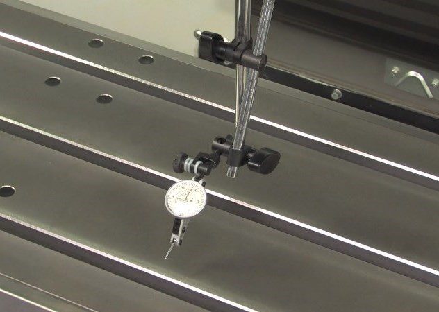
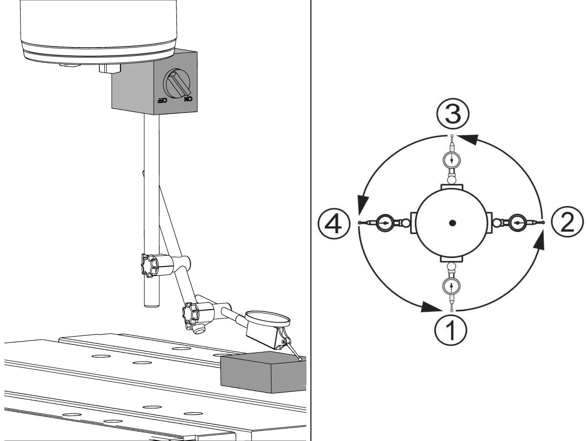
Jogga Z-axeln till mitten av resan. Fäst test indikatorn på den magnetiska basen och fäst den magnetiska basen längst ner på spindeln.

Placera test indikatorn för att mäta en 10" (250mm) diameter cirkel i mitten av bordet.

Placera tabellen så att test indikatorn sitter kvar på bordet (inte över en t-kortplats) när den är vänd mot både fram-och kolumn sidorna på maskinen.

Vänd indikatorn mot maskinens framsida, sänk Z-axeln i tionde (0,0001") och ta ner test indikatorn för att kontakta tabellen.

Nollställs indikatorn.

2

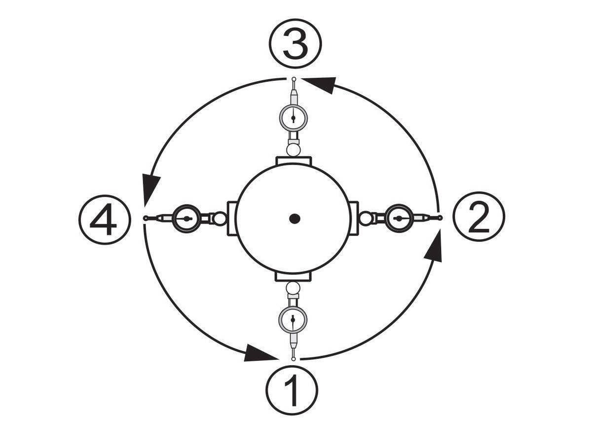
Vrid spindeln för hand och ta en avläsning var 90 grader för att ge två värden längs både X-axeln och Y-axeln.

Skillnaden mellan indikatorns avläsningar för varje axel bör inte överstiga 0,0005" (0,013 mm).

3

Lås utjämningbultarna på plats genom att dra åt låsmuttern medan du håller Utjämnings skruven.

Se till att Utjämnings skruvarna inte rör sig under denna process.

Om spindel Svepet är ute Kontrollera att maskinens nivå är korrekt.

För en mer fördjupad guide om hur du utför denna procedur, vänligen se:

VMC spindel Svep

Lubrication Verification

1

Run the spindle run-in program.

 Note: For 10K spindles and above use a balanced tool holder

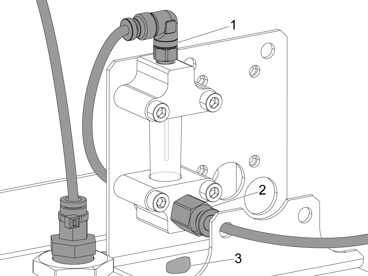
Examine the sight glass, make sure the correct number of drops are fall through the sight glass.

Examine the fittings [1,2] on top of the oil pump tank.

The oil collects on top of the oil pump tank [3] either behind or in front of the sight glass bracket, underneath the leaking fitting.

Tighten any leaking fittings.

2

Go to the Maintenance tab.

Press [F2] to cycle an axis lubrication test.

Inspect the gauge on the lubrication system.  Make sure it holds pressure.

MiniMill-EDU Machines

1

För MiniMill EDU-maskiner:

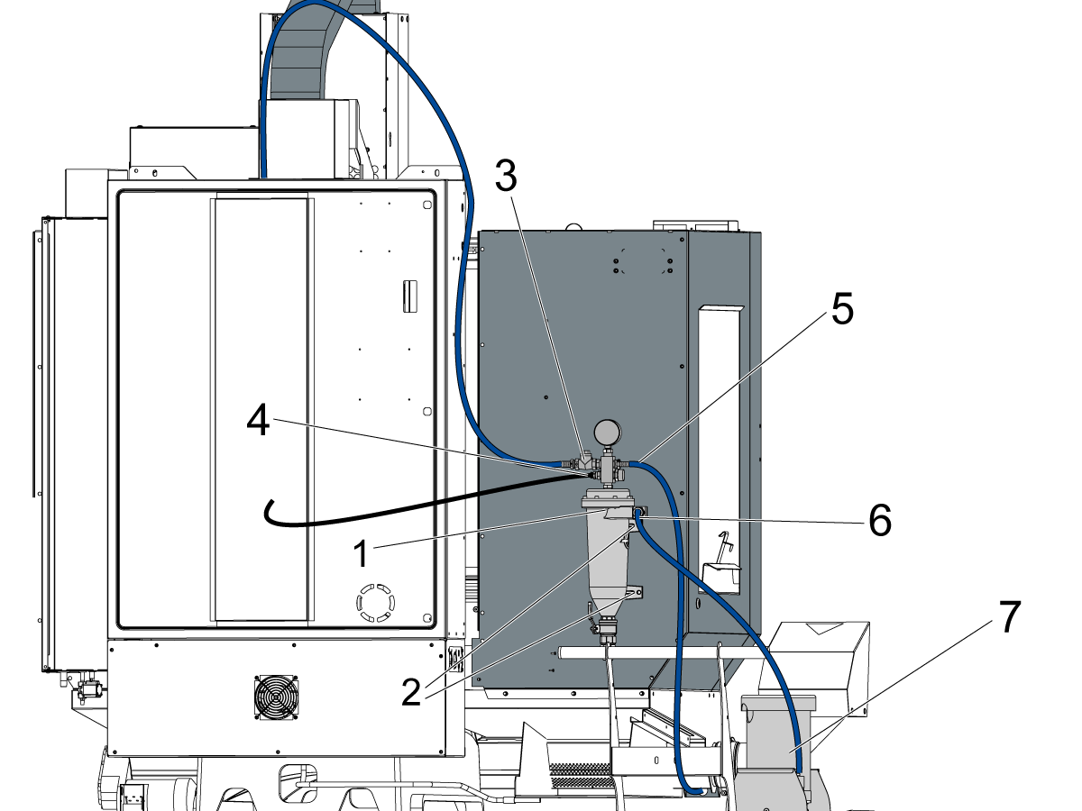
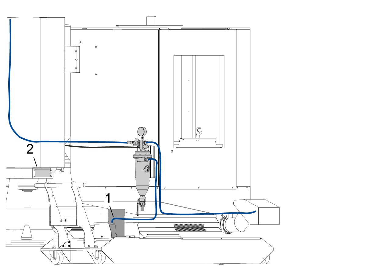
Om maskinen har tillvalet 93-1001072 för fältinstallation av 45 gl kylmedelstank, måste spånavskiljaren och kylvätsketanken monteras.

Montera kylmedelsfiltret [1] genom att fästa det på baksidan av panelkåpan med FBHCS [2]. Anslut sedan slangarna och dra dem enligt följande beskrivning:

Dra den blå kylmedelsslangen [3] från spånavskiljarens ovansida till vänster till kopplingen i spindeldockan.

Dra den svarta kylmedelsledningen [4] från tryckanslutningen till den bakre Y-axelns waycover Wash Down-kontakt. Slangen ska dras genom pelargjutgodset.

Dra den blå kylmedelsslangen [5] från det övre högra hörnet av spånavskiljarenheten till fästet för tvättpistolen för kylmedlet.

Anslut den blå kylmedelsslangen [6] från spånavskiljarens mittersta del till kylvätskepumpen [7].

2

För MiniMill EDU-maskiner:

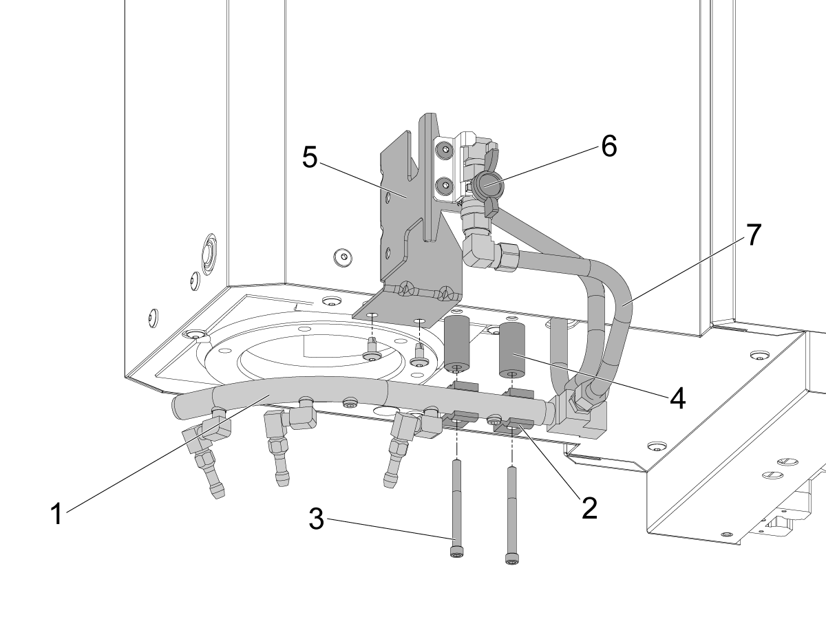
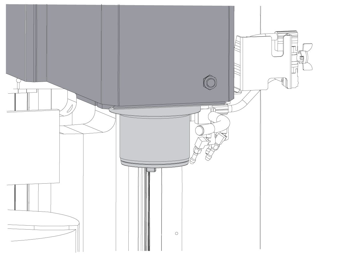
Montera kylmedelsringen genom att fästa den på spindeldockan.

Använd de långa SHCS [3] och båda skenklämmorna för kylmedel [2] för att montera kylmedlets skenanordning [1].

Använd distansbrickorna [4] mellan skenan för kylmedlet och spindeldockan.

Fäst P-COOL monteringsfästet [5] på spindeldockan med BHCS.

Dra slangen från spindeldockan till kylmedelsventilen [6].

Dra den andra slangen [7] från ventilen till skenan för kylmedlet

Obs! Kontrollera att alla kopplingar är åtdragna för att förhindra kylmedelsläckage.

Obs! Om maskinen beställdes från fabriken med tillvalet 45 gl kylmedel behöver dessa steg inte utföras. De behöver bara utföras för fältinstallationssatsen 93-1001072. Kontrollera att tillvalet fungerar genom att utföra testerna som beskrivs i nästa avsnitt.

Option Installation Guides

Kontrollera och testa att alla tillvalsfunktioner har installerats korrekt.

Installera handjoggningsenhet (RJH-touch)
Installera Wi-Fi-kamera
Bekvämlighetspaket
Extra kylmedelsfilter
Installera CABCOOL
Installera PulseJet
HAAS oljeupptagare
Arbetsbordsbelysning
Verktygsluftutsläpp
Automatisk luftpistol

Final Testing

1

Anslut kylvätskepumpen och pump (TSC) till genom spindel (om sådan finns).

Anslut den blå kyl vätskeslangen från filter öppningen till kyl vätske pumpens utlopp.

Anslut kylvätskepumpen till lågtrycks skär vätske pluggen.

Fäst TSC-pumpen på den lilla lila kyl vätskeslangen.

Anslut TSC-pumpen till högtrycks kyl kontakten.

Anslut kylvätskenivå sensorn och andra relaterade sensorer till motsvarande pluggar.

2

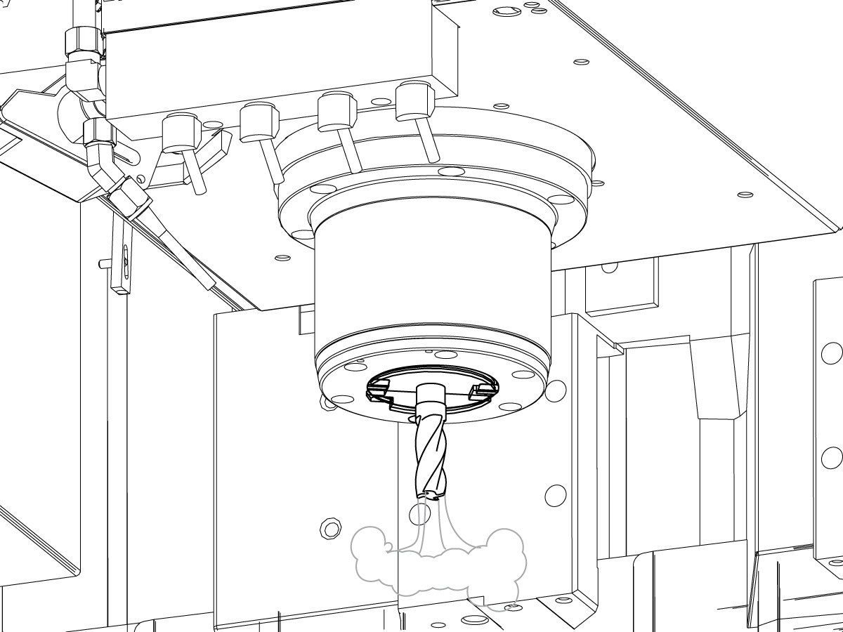
Testa översvämnings kylning.

Öppna ventilen för kyl medels ringen och Stäng operatörs luckan före detta test.

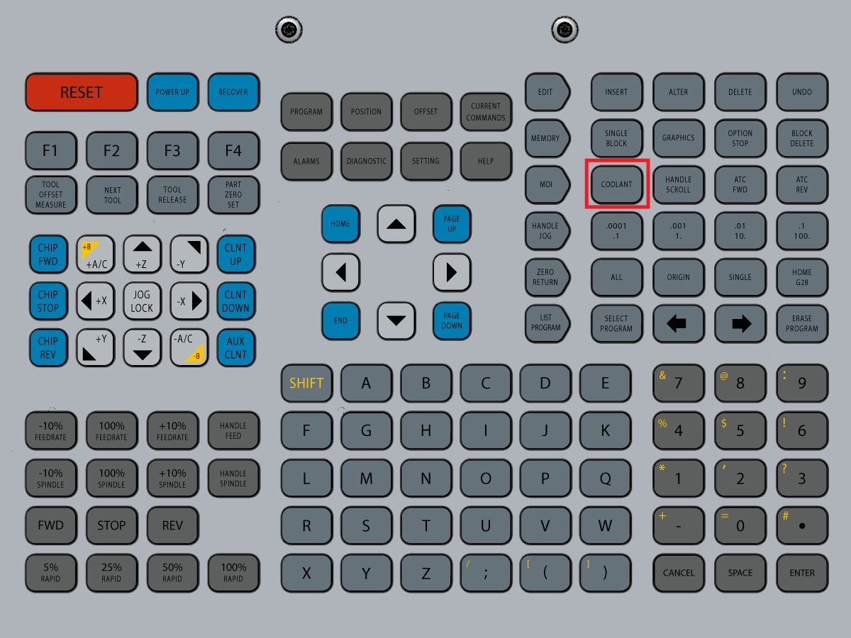
Tryck [COOLNT] på styrsystemet. Skärvätskan ska översvämmas av munstyckena.

Tryck [COOLNT] igen för att stoppa flödet.

3

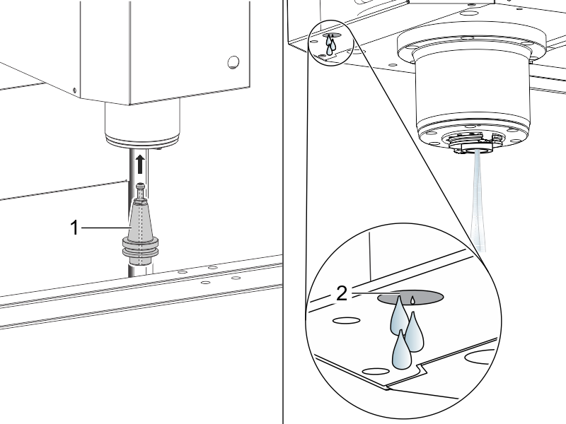
Testa kylvätskan genom spindeln (TSC) (om sådan finns).

Sätt en TSC-verktygshållare [1] i spindeln.

Tryck [AUX CLNT] för att starta TSC.

Korrekt funktion är följande:

  1. Kylvätskan flödar korrekt från TSC-verktygshållaren.
  2. Några droppar flöde från vakuum-Generator slangen [2].

Tryck på [RESET].

4

Stoppa spindeln.

Kör programmet spindelns run-in.

Inkörning av spindeln

5

Testa Spånskruven (om sådan finns).

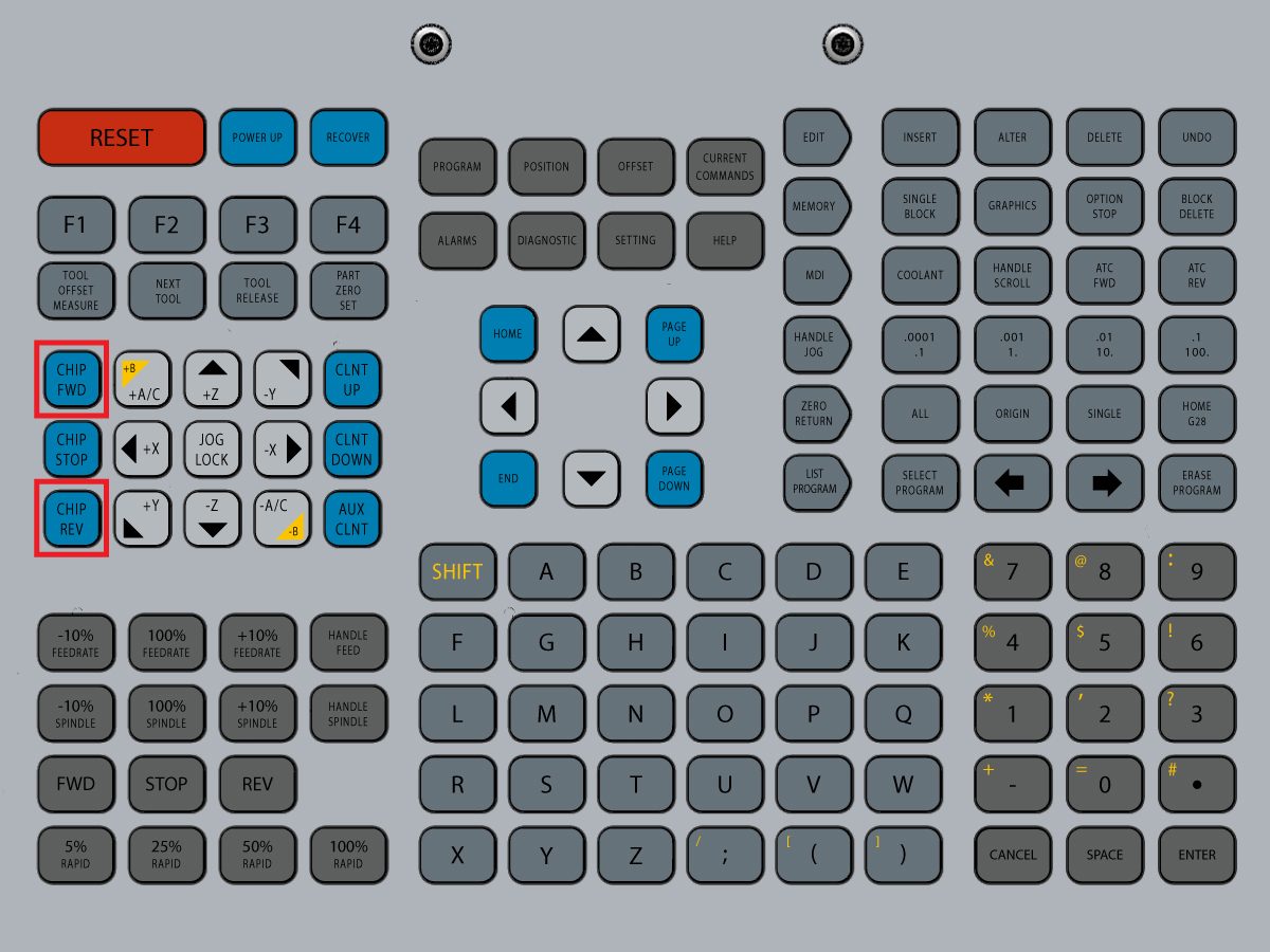
Tryck på [CHIP FWD] och[CHIP REV] på styrsystemet.

6

Testa dörr spärrarna.

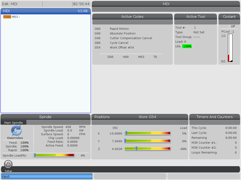
Tryck [MDI], Skriv in S500 M03, och tryck på [ENTER].

Se till att maskinen inte är i Ställ in läge genom att kontrollera strömbrytaren på sidan av Hänget.

Tryck [CYCLE START] med dörren öppen. Maskinen ska säga att stänga luckan och trycka på [CYCLE START].

Tryck [CYCLE START] med dörren stängd. Den Interlock stift bör sträcka sig och spindeln ska börja snurra.

Försök att öppna dörren med spindeln snurrar. Spindeln ska inte sluta rotera.

7

Testa Luftblåsning (TAB) för genomgående verktyg (om sådan finns).

Använd denna kod i MDI-läge:

M73

G04 P5.;

M74

G04 P3.;

M99

M73 startar TAB. M74 stoppar TAB.

Manövrera fliken manuellt:

Tryck på [AUX CLNT]. Tryck på pilen  [RIGHT] DOWN (ned).

Verktygets luft sprängning startar.

Tryck på [AUX CLNT].

Verktygets luft sprängning stoppas.

8

Testa nyckel brytare.

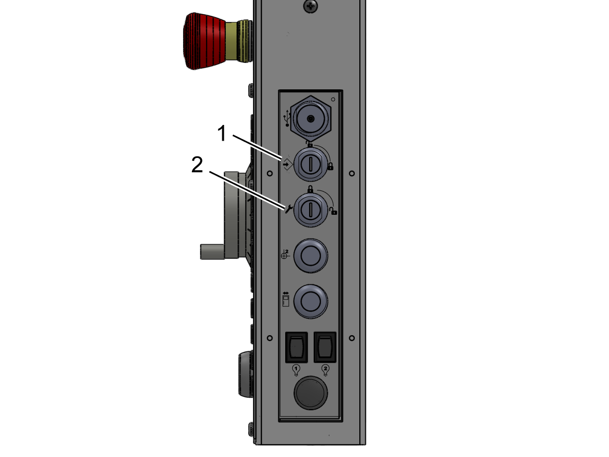
Sätt i Setup/Run lock-tangenten (#2007) till den nedre nyckel facket och vrid till olåst läge.

Kontrollera att nyckeln bara kan tas bort från låst läge.

Sätt i minnes låsknappen (#2341) på den övre knapp luckan och vrid den till låst läge.

Kontrollera att nyckeln kan tas bort från endera positionen.

Med minnes låstangenten i låst läge kontrollerar du att ändringar inte kan göras i inställningarna eller programmen.

9

Kontrollera att en fönsterspärr är installerad i varje sidoåtkomst fönster.

(Detta gäller inte för fasta sido fönster på DM-och DT-seriemaskiner.)

Kontrollera att spärren aktiveras för varje fönster för att hålla fönstret i upp-läget.

Kontrollera att fönster låsen är installerade på varje sidofönster.

Kontrollera att Windows-låset stängs i nedfällt läge.

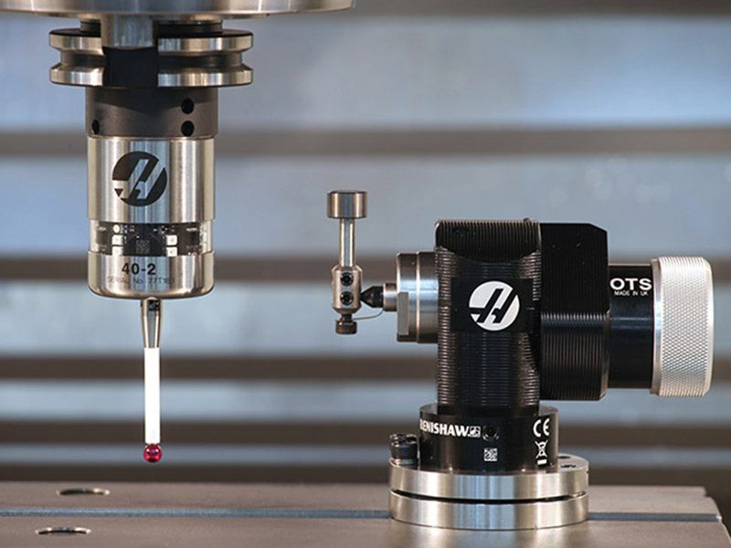
Install and Calibrate WIPS

1

Installera och kalibrera det trådlösa intuitiva sond systemet (WIPS) (om det är utrustat).

För en djupgående guide om WIPS installation och kalibrering, se:

WIPS - Installation

3.2 Reboot MM/SMM – Installation

Recently Updated

Mini Mill/Super Mini Mill – Installation


Introduction

Den här proceduren används för installation av Minimill (MM) och Super Minimill (SMM). För att installera en Minimill eller Super Minimill, läs mer i proceduren Minimill/Super Minimill – Installation. 

För att avgöra vilken typ av Minimill-version du har, se referensdokumentet Minimill/Super Minimill – Maskinversion – Identifiering.

Verktyg som krävs:

  • 3/4" Socket
  • 5/32", 1/4", 3/8" Hex-Bitarsuttag
  • Ratchet
  • 3/4", 1.5" Skiftnyckel
  • Måttband
  • 0,0005" eller 1 micron test indikator och magnetisk bas
  • T-2181 SERVICE verktyg, UTJÄMNINGS verktyg eller precisions Maskinistisk nivå, 0,0005" Division

Leveling Screws Hardware

Note: The washers [1] and nuts [2] are installed during shipping and should be saved for installation and not be discarded.

Note: The washer orientation [3] is important.  The conical part of the washer should be against the casting,  see illustration.

Remove Rust Inhibitor

To safely and effectively remove rust inhibitor from way covers and other non-painted surfaces:

Initial Scraping

  • Use a plastic scraper to remove the bulk of the rust inhibitor.
  • Avoid using metal tools to prevent scratching or damaging the surface.

 Important: Do not use scotch-brite or metal scrapers, these will scratch the way covers.

Chemical Cleaning

  • Spray the affected areas with a heavy-duty citrus cleaner or Simple Green.
  • Ensure full coverage of all non-painted surfaces coated with rust inhibitor.

Soak Time

  • Allow the cleaner to soak for several minutes to loosen remaining residue.

Wipe Down

  • Use a clean shop towel to thoroughly wipe off the softened rust inhibitor.

Rust Proofing

  • Apply mineral spirits or WD-40 to all exposed metal surfaces to prevent future rust formation.

Important: Always wear gloves and eye protection when handling chemical cleaners. Dispose of used towels and cleaning agents according to local environmental regulations.

 Important: To avoid any contamination of the way cover seals with the sticky residue. Do not move any of the axes until all the rust inhibitor has been removed.

Rust Inhibitor - Safety Data Sheet (SDS)

Air Connection

Electrical Installation

 DANGER: Working with the electrical services required for CNC machines is extremely hazardous and can result in serious injury or death.

Before connecting line wires to the CNC:

  • Turn off all power to the machine at the source.
  • Perform a Lockout-Tagout (LOTO) procedure to ensure the power remains off during service.
  • Verify that power has been disconnected by using an AC voltage detector on all incoming lines.

If you are uncertain about how to safely disconnect power or perform LOTO procedures:

  • Do not proceed.
  • Contact qualified personnel or obtain appropriate assistance before continuing.

Failure to follow these precautions may result in electrical shock, equipment damage, or fatal injury.

1

Initial Control Inspection

Danger: At this point, there should be no electrical connection to the machine. Electrical panel must be closed and secured. When main switch is on, there is HIGH VOLTAGE throughout the electrical panel (including the circuit boards and logic circuits) and some components operate at high temperatures. Therefore, exercise extreme caution when working in the panel.

  • Set the main breaker switch at the upper right of the electrical panel on the back of the machine to OFF.
  • Using a screwdriver, unlock the two latches on the panel door, unlock the cabinet with the key and open the door.
  • Take sufficient time to check all the components and connectors associated with the circuit boards. Look for any cables that have become disconnected, look for any signs damage and loose parts in the bottom of the panel box. If there are any signs that the machine was mishandled, call the factory before proceeding.

2

1-Phase Machines: Insert each power lead into the wire cover.  Connect the two power leads to L1 and L3 terminals on top of the main circuit breaker.

3-Phase Machines: Insert each power lead into the wire cover.  Connect the three power leads to L1, L2 and L3 terminals on top of the main circuit breaker.

Connect the separate ground line to the ground bus to the left of the terminals.

For 3-phase machines, check to see what type of power configuration is supplying the machine. Take voltage measurements of each power lead to ground line. Then refer to RD0084 - Input Power Configurations to determine which power lead should be connected to the L1 terminal based of the voltage readings and power configuration.

Refer to Haas Main Circuit Breaker - Torque Specifications for what value to torque the circuit breaker power leads.

 Note: Make sure that the leads actually go into the terminal-block clamps . (A poor connection will cause the machine to run intermittently or have other problems, such as servo overloads.) To check, simply pull on the wires after the screws are tightened.

3

After the line voltage is connected to the machine, make sure that main circuit breaker (at top-right of rear cabinet) is OFF . Remove the Lockout / Tagout and Turn ON the power at the source. Using a digital voltmeter and appropriate safety procedures: 

1-Phase Machines: Measure the AC voltage across L1 & L3 at the main circuit breaker.  The AC voltage must be between 220 - 250 volts .
Note: Lower or higher than this voltage can generate low/high voltage alarms.

3-Phase Machines : Measure the AC voltage between all three pair phases at the main circuit breaker. 

The AC voltage must be between 195 and 260 volts (360 and 480 volts for high voltage option).

SMinimill - Reboot: The AC voltage must be between 198 and 242 volts for machines without a high voltage transformer.  Refer to the Minimill/SMinimill - Identification document.

 Note: Wide voltage fluctuations are common in many industrial areas; minimum and maximum voltage supplied to a machine while it is in operation must be known. U.S. National Electrical Code specifies that machines should operate with a variation of +5% to -5% around an average supply voltage. If problems with line voltage occur, or low line voltage is suspected, an external transformer may be used. If you suspect voltage problems, voltage should be checked every hour or two during a typical day to be sure it does not fluctuate more than +5% or -5% from an average.

4

Important: With the main circuit breaker turned OFF.

Check the transformer taps at the bottom-right corner of the rear cabinet.

1-Phase Machines: The input voltage cable must be moved to the connector which corresponds to the average voltage measured in the above step.

3-Phase Machines:  The input voltage cables labeled 74, 75, and 76 must be moved to the terminal block triple which corresponds to the average voltage measured in the above step.

5

Transformer T5 supplies 24VAC used to power the main contactor. There are two versions of this transformer for use on a 240 and 400V machines. The 240V transformer has two input connectors located about two inches from the transformer, which allow it to be connected to either 180-220V or 221-240V.

Users that have 220V-240V RMS input power should use the connector labeled 221-240V, while users with 190-220V input power should use the connector labeled 180-220V. Failure to use the correct input connector will result in either overheating of the main contactor or failure to reliably engage the main contactor.

The 480V (option) T5 transformer has three input connectors, labeled 340-380V, 381-440V and 441-480V.

Users with 340-380V 50/60Hz power should use the 340-380V connector while users with 380V-440V 50/60Hz power should use the 381-440V connector.

Important: Set the main circuit breaker to ON. Check for evidence of problems, such as the smell of overheating components or smoke. If such problems are indicated, immediately set the main circuit breaker to OFF and call the factory before proceeding.

After the power is on, measure the voltage across the bottom terminals on the main circuit breaker. It should be the same as the measurements where the input power connects to the main breaker. If there are any problems, check the wiring.

6

Apply power to the control by pressing the Power-On switch on the front panel.

Check the DC Voltage and AC Line Voltage gauges in Diagnostics. The DC Voltage gauge must read between 310 - 360V. The AC Line Voltage must be between 90 and 105 percent. If the voltage is outside these limits, turn off the power and recheck steps 2 and 3. If the voltage is still outside these limits, call the factory.

7

Electrical power must be phased properly to avoid damage to your equipment. The Power Supply Assembly PC board incorporates a "Phase Detect" circuit with neon indicators. When the orange neon is lit (NE5), the phasing is incorrect. If the green neon is lit (NE6), the phasing is correct. If both neon indicators are lit, you have a loose wire; check the connections. Adjust phasing by setting the source power to off and then swapping L1 and L2 of the incoming power lines at the main circuit breaker.

Danger: ALL POWER TO CNC MUST BE TURNED OFF LOCKOUT-TAGOUT AT THE SOURCE PRIOR TO ADJUSTING PHASING. ALWAYS DOUBLE CHECK THE INCOMING LINES WITH AN AC VOLTAGE DETECTOR.

Turn off the power and set the main circuit breaker to OFF. Close the door, lock the latches, and turn the power back on.

Remove the key from the control cabinet and give it to the shop manager.

8

Activation

When the machine is properly placed and connected to both air and electrical power, it is ready for final installation (removing shipping blocks, leveling, spindle sweep, etc.) and software activation. The HFO service technician does this. Contact the local HFO to schedule the work.

IMPORTANT:  Machines equipped with motion sensors must be rough‑leveled before attempting to arm the motion sensor.  For detailed instructions, refer to Service Notification - SA0007.  Access to this document is restricted to Haas Factory Outlet personnel.

Shipping Bracket Removal

1

Ta bort de (2) översta skruvarna [1] som håller pendeln i låst läge.

Vrid ut pendeln så att du kommer åt övriga (2) skruvar [2] intill pendelns gångjärn och ta bort dem. 

Ta bort ledbulten [3] som håller fast operatörsdörren. Du kommer åt bulten via operatörsdörrens öppning. 

Inuti maskin, ta bort bultarna som fäster spindel skeppnings fästet [4] från bordet till spindelnhölje. 

 OBS!!  Spindel fästet kommer inte att kunna tas bort på denna punkt. Ta bort fästet efter att du har strömat upp maskinen och joggat spindeln uppåt

Machine Leveling

IMPORTANT:  Machines equipped with motion sensors must be rough‑leveled before attempting to arm the motion sensor.  For detailed instructions, refer to Service Notification - SA0007.  Access to this document is restricted to Haas Factory Outlet personnel.

1

Clean and jog the table so the spindle is on the center of travel.

Place the level on top the table aligning the long vial to be parallel with the X-axis. Use the T-slots as reference.

The long vial on the level represents the X axis and the short vial on the level represents the Y axis. 

Loosen the (4x) leveling screws on the corners of the base. Make small adjustments  to leveling screws 1 and 3 to adjust the X axis level. After each adjustment, note the position of the  bubble in the short vial. 

If the position of the bubble in the short vial isn't centered, make adjustments to leveling screws 1 and 2 as required. 

Repeat this process until both bubbles are in their center positions. 

2

Adjust (x4) leveling screws to be snug against the ground. 

Jog the table towards the spindle column while observing the position of the bubble in the long vial. If the bubble is not centered, make a small adjustment to the lower corner 1 & 3 if titled towards the column end or on the higher corner 2 & 4 if tilted towards the operator end.

Repeat this process with the table on the other end of the machine. 

Spindle Sweep Check

1

Attach indicator to spindle head. Position the table and indicator to sweep a circle 10" in diameter.
 
Place a gauge block on the table.
 
Jog the spindle down and zero the indicator at Position 1. 
 
Using a gauge block every 90 degrees, check that the difference in these measurements don't exceed 0.0005". If it does, check the machine level.

Lubrication Verification

1

Run the spindle run-in program.

 Note: For 10K spindles and above use a balanced tool holder

Examine the sight glass, make sure the correct number of drops are fall through the sight glass.

Examine the fittings [1,2] on top of the oil pump tank.

The oil collects on top of the oil pump tank [3] either behind or in front of the sight glass bracket, underneath the leaking fitting.

Tighten any leaking fittings.

2

Go to the Maintenance tab.

Press [F2] to cycle an axis lubrication test.

Inspect the gauge on the lubrication system.  Make sure it holds pressure.

Convenience Package Install

1

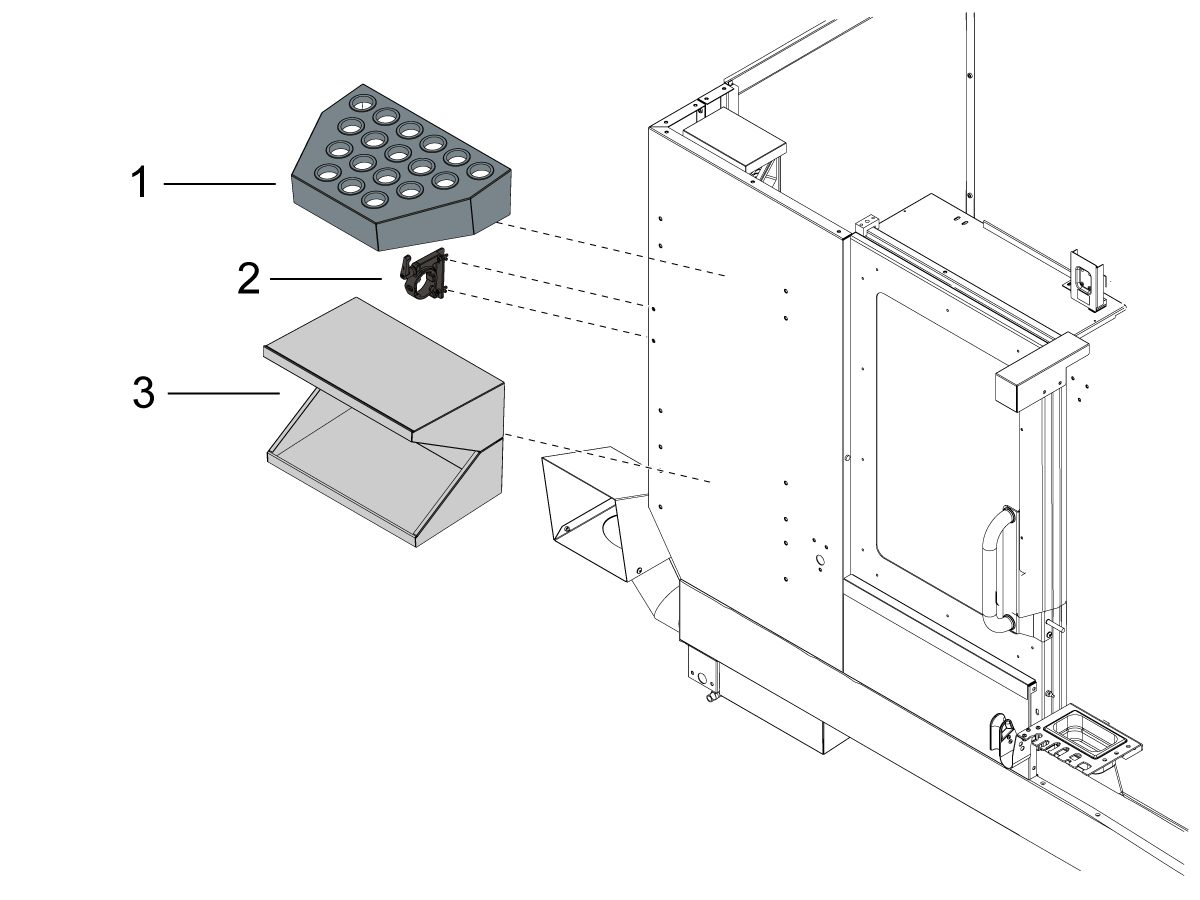
Fäst verktygsfacket [1] på framsidan av maskinens kåpa. 

Fäst stålhållaren [2] under verktygsfacket [1] på framsidan av maskinens kåpa.

Fäst skrivbordet [3] under stålhållaren [2] på framsidan av maskins kåpa.

Coolant Hose Installation

1

Anslut den blå kyl vätskeslangen från filteröppningen till kylvätskepumpens utlopp [1].

Anslut kylvätskepumpen till lågtryckskylmedelspluggen [2]. 

Montera kylmedelsgivaren. Läs mer i Flottörgivare för kylmedel – NGC – Montering. 

Flottörgivare för kylmedelsnivå – NGC – Montering

Machine Operation

1

Test spindel drift

Kör spindelns inkörningsprogram O09221.

Kör ett vibrationstest om missljud hörs från spindeln. En vägledning om spindelvibrationstest finns i: 

Vibrationsanalys-Ethernet-gränssnitt
Vibrationsanalys - RS-232-gränssnitt

2

Test av skär vätske drift

Fyll kylvätskestanken med kylmedel.

Starta kylmedel genom att trycka på [COOLANT] (KYLMEDEL) på hängpanelen.

3

Testa dörr spärrarna

Tryck på [MDI]. Skriv in S500 M3; Tryck [ENTER].

Kontrollera att enheten inte är i INSTÄLLNINGSLÄGE genom att kontrollera nyckelbrytaren på hängpanelens sida

Med dörren öppen trycker du på [CYKELNS START]. Maskinen ska uppmana operatören att stänga dörren och trycka [CYCLE START].

När luckan är stängd trycker du på [CYKELNS START]. Spärrstiftet ska matas ut och spindeln börja rotera.

 viktigt: När spindeln roterar testar du dörrlåsen genom att försöka öppna dörren. Spindeln ska inte sluta rotera. 

4

Testa säkerhetsfunktioner

Sätt i Setup/Run lock-tangenten (#2007) i det nedre nyckelfacket [2] och vrid till olåst läge.

Kontrollera att nyckeln bara kan tas bort från låst läge.

Sätt i minneslåsknappen (#2341) på den övre knappluckan [1] och vrid den till låst läge.

Kontrollera att nyckeln kan tas bort från endera positionen.

Med minnes låstangenten i låst läge kontrollerar du att ändringar inte kan göras i inställningarna eller programmen.

Kontrollera att båda fönstren låses i nedre läge. 

5

Spåntransportör

Testa Spånskruven (om sådan finns).

Tryck på [CHIP FWD] och[CHIP REV] på styrsystemet.

6

WIPS kalibrering NGC 

Om din maskin inkluderar WIPS-alternativet, se följande länk för instruktioner om kalibreringsproceduren:

WIPS kalibrering NGC

Mill Maintenance Schedule

Håll dina Haas-maskiner på topp prestanda samtidigt som du undviker oplanerad driftstoppen. Ett underhållsprogram kan du hantera ditt schema i stället för att fastna med tidiga överraskningar. Vänligen se länken nedan för rekommenderade underhållsintervall.

Fräsar – Underhållsschema

3.3 Förankring

Recently Updated

Instruktion för förankring


Introduction

This procedure will show you how to install the Drop-In expansion style anchors to a Haas CNC.

NOTE: If the machine was built before Jan 2020 or is a VS or HDC series machine, please refer to the epoxy style anchoring procedure (AD0212) click here.

For instructions on how to anchor the various components for the Haas Cobot kits refer to the Haas Cobot - Anchoring instruction page.

This procedure applies to the following Service Kits:

Mill
Model Part Number
DC-1 93-1001018
DC-2 93-1001019
DC-4 93-1001211
DT/DM 93-1000601
EC-400/VC-400

93-1000567

See Note Below

EC-500/50 93-1001145
EC-1600/UMC-1600H 93-1000535
EC-630 93-1000856
GM-1 93-1001115
GM-1XT 93-1001235
GM-2-3AX 93-1000574
GM-2-5AX 93-1000542
GR-510 93-1000574
GR-712 93-1000574
MM/SMM Reboot 93-1001016
UMC-350HD 93-1000780
UMC-400/SS 93-1001224
UMC-500/SS 93-1000379
UMC-750/SS (NON REBOOT) 93-1000380
UMC-750/SS (REBOOT)  93-1000381
UMC-1000/SS (REBOOT) 93-1000381
UMC-1250/SS 93-1000644
UMC-1500-DUO/SS-DUO 93-1000871
VF-1/2, VF-2TR, VF-2SS 93-1000534
VF-2YT, VF-2SSYT, VM-2 93-1000549
 VF-3/3SS, VF-4/4SS 93-1000550
VF-3YT/3YTSS, VF-3YT/50, VF-5/40, VF-5/40TR, VF-5/40XT, VF-5SS, VF-5/50, VF-5/50TR, VF-5/50XT, VM-3, VMT-750 93-1000548
VF-6/40, VF-6SS, VF-6/40TR, VF-7/40, VF-6/50, VF-6/50TR, VF-7/50, VM-6 (Base with 8 leveling feet) Built between January 2020 and September 6th 2023 93-1000547
VF-8/40, VF-9/40, VF-8/50, VF-9/50, VR-8, VR-9 (Base with 8 leveling feet) Built between January 2020 and October 6th 2023 93-1000546
VF-10/40, VF-12/40, VF-10/50, VF-12/50 (Base with 8 leveling feet) 93-1000545
VF-11/40, VF-11/50, VR-11 (Base with 8 leveling feet) 93-1000544
VF-6/6TR/6SS/7/10/12 both 40T & 50T and VM-6 (Base with 6 leveling feet) Built September 7th 2023 and later 93-1000999
VF-8/9/11/14 both 40T & 50T and VR-8/9/11/14 (Base with 6 leveling feet) Built October 7th 2023 and later 93-1001000
VS-3 93-1000870
Updated
Note: For EC-400 anchor kit 93-1000567 only. EC-400 Anchor Template 96-0286 only permits 7 of the 8 anchor locations to be utilized. The anchor spot under the front door is inaccessible due to improper enclosure spacing. This is corrected with EC-400 Anchor Template 96-0286A, which shifts the front anchor location to a more accessible spot. 
 
Pallet Pool/RPL
UMC-500PP 93-3526
UMC-750PP (V1) See Note Below
UMC-750PP (V2) 93-3527
UMC-1000PP (V2) 93-3527
UMC-1250PP See Note Below
EC-400PP 93-3525
VF-2YTPP See Note Below
VF-4 PP See Note Below
Robot Pallet Loader See Note Below
Note: There is currently no 93-xxxx service kit for the following models:
  • (30-12644B + 96-0316A) UMC-750 Pallet Pool (V1)
  • (30-12644B + 96-0364) VF-2YT Pallet Pool
  • (30-12644B + 96-0383) VF-4 Pallet Pool
  • (30-12644B + 96-0388) Robot Pallet Loader

You would need to order individual parts,  please contact your Local Haas Factory Outlet for availability.

Lathe
Model Part Number
ST-10/10Y/15/15Y 93-1000378
ST-10L/10LY/15L/15LY 93-1000855
ST-20/25/20Y/25Y 93-1000552
ST-20L/20LY/25L/25LY/28L/28LY 93-1001005
ST-30/35/30Y/35Y, DS-30Y (REBOOT ONLY) 93-1000541
ST-30L/35L/LY 93-1001079
ST-40 93-1000540
ST-40/40Y (Reboot) 93-1000819
ST-40L 93-1000539
ST-40L (Reboot) 93-1000820
ST-40S/45S/SY  93-1001012
ST-50/55 93-1000538
TL-1 93-1000537
TL-2 93-1000536
Extended Liner System
ST-10/10L/10Y/10LY 93-1000844
93-1000845

Tools required:

  • Paint markers
  • Painters Tape
  • Pipe cleaner brush
  • 5 lb. Sledge Hammer
  • SDS Plus Hammer Drill
    Note:  The SDS-Plus Hammer drill should be rated for 1" bit.

Video Instructions

Anchor Template Placement

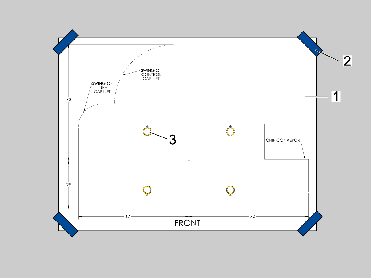
  1. Unroll machine anchoring template [1].
  2. Use centerlines and provided reference sheet dimensions, measure distances to nearest allowable obstructions.
  3. Once position is established, taped the corners [2] of the anchoring template to the foundation.  Keep the template as flat as possible.
  4. Spray paint the foundation in the cutout areas of the template [3].
  5. Let the paint dry for 5-10 minutes.
  6. Remove the anchoring template [1].

Drill Holes and Set the Anchors

Use the provided SDS-Plus Style drill for the following steps:

  • Drill specified number of 5/8" holes at depth 2.00 - 2.25" each.  
    • Drill bit should be perpendicular to foundation.
  • Clean the holes with pipe cleaner.
  • Use compressed air and a vacuum to clear holes.
  • Repeat for the number of leveling pads.
  • Cover the holes with tape to protect from unwanted debris while the other holes are drilled.
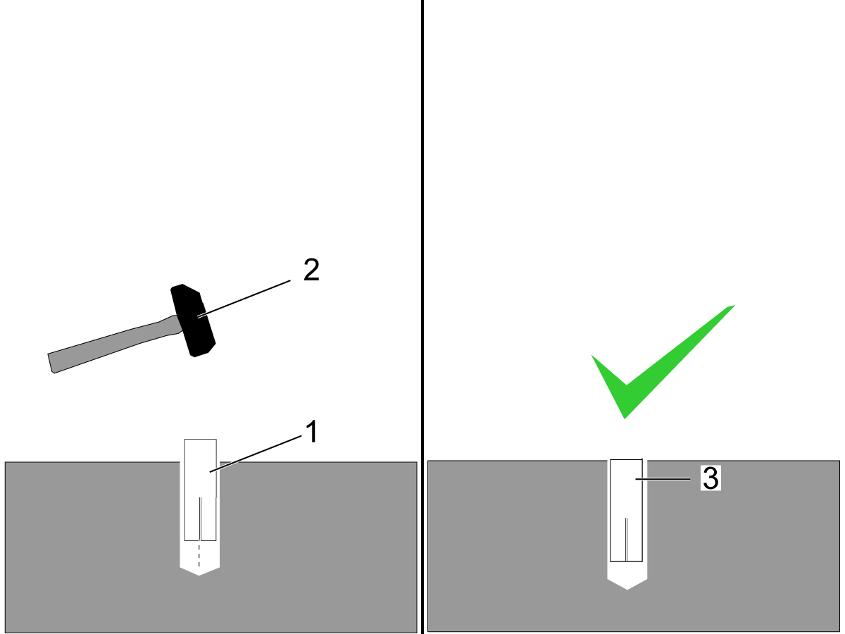
  • Using the hammer [2] set the drop-in anchor [1] flush with the concrete [3].

    Note:  Do not use the set tool to drive the anchor.  
  • Use the provided setting tool [1] and hammer [2], to seat the anchor in the concrete.
  • Make sure that the anchors are seated flush [3], use the setting tool as a gauge.
    Note:  Be careful not to overdrive the anchor [4] to far inside the hole.

Machine Placement

  1. Once the anchors are set, place the leveling pads on the spray painted cross-hairs.
  2. Place the machine on the leveling pads.
  3. Set the machine height.
  4. Level the machine
  5. Tighten down the machine locknuts.

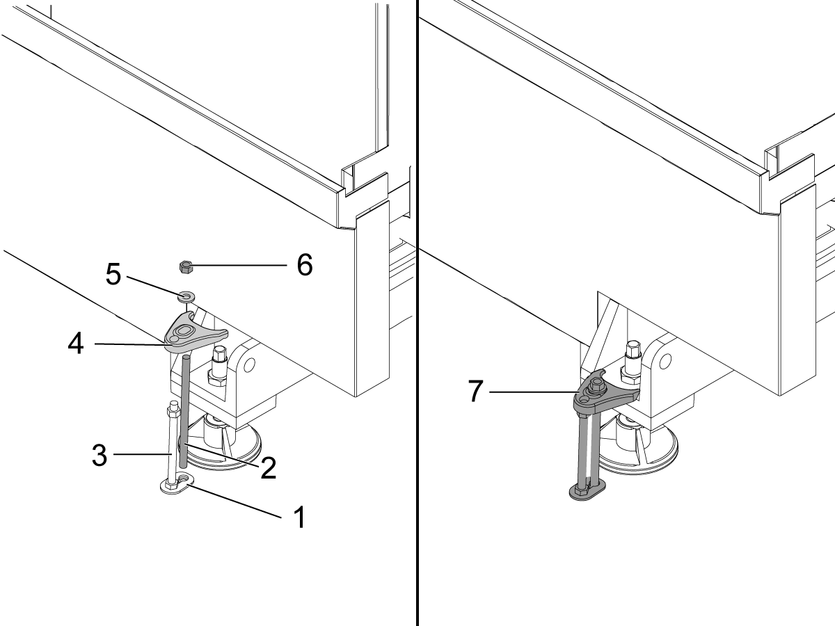
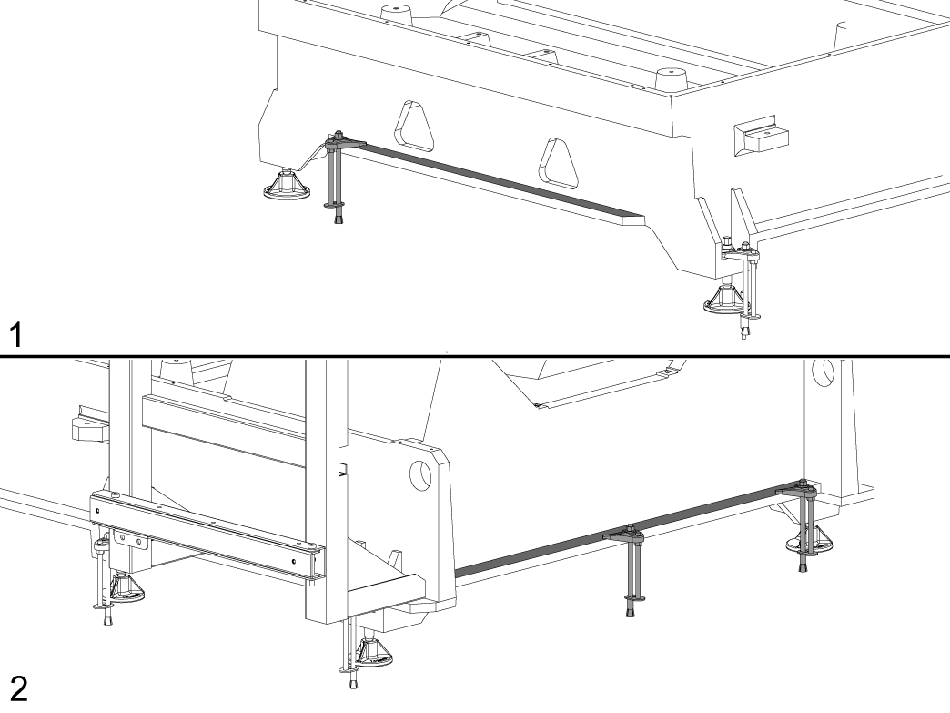
Anchoring Strap Installation

  1. Place the thrust plate flush [1] with the foundation.
  2. Thread stud [2] into the anchor location using two lock nuts.
  3. Place 1/2-13 hex nut on the 1/2-13 hex bolt [3] on top of the thrust plate.
  4. Place the anchoring strap [4].
  5. Place the washer [5] on the threaded rod.
  6. Thread the 1/2-13 hex nut [6] into the threaded rod.
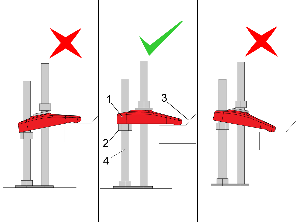
  7. Be sure the anchoring strap [7] remains parallel to the clamped casting surface.
  8. Torque 1/2-13 hex nut to 25ft-lbs (34 nm).

Make sure that the anchor strap [1] is level on the hex nut [2] and the machine base [3].

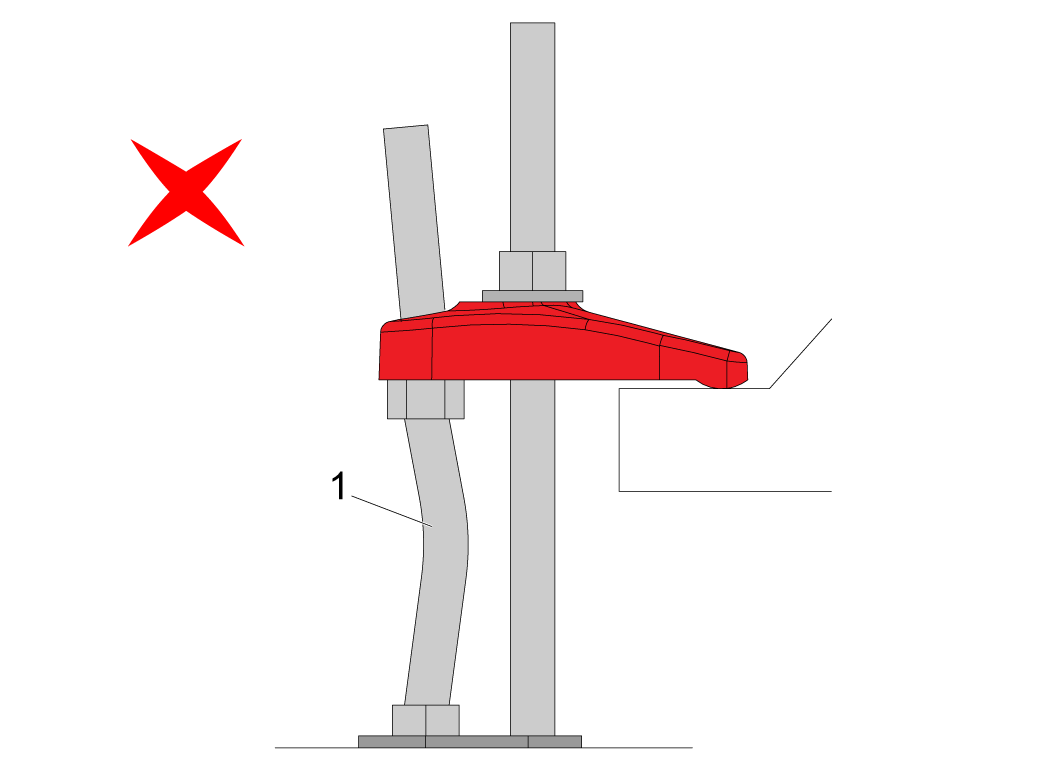
NOTE: Make sure the threaded stud [4] is perpendicular to the floor and not bent. 

Make sure the threaded stud welded to the base is not bent as shown in the image [1].

If this occurs make sure that the anchor holes are drilled straight and re-drill them if necessary. 

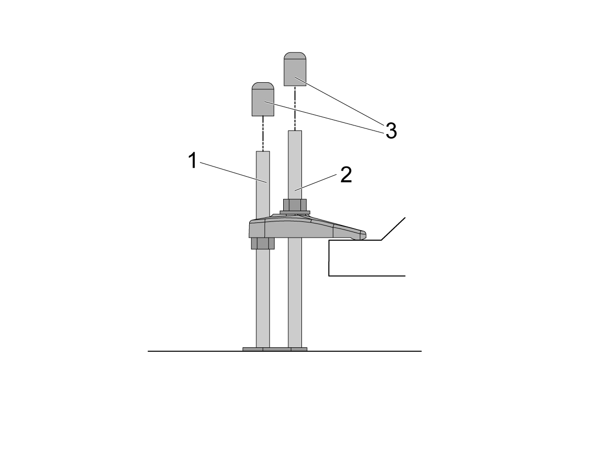
If there is clearance on the anchor [1] and stud [2] place the end caps [3] on the ends as shown in the image. Place these caps on all all anchors.

NOTE: The UMC-1250/SS does not have the anchoring fingers on the base foot. The indicated holes on the anchoring layout will have them anchoring down the base flange as shown in the image. Image [1] is the front of the machine, while image [2] is the back of the machine. 

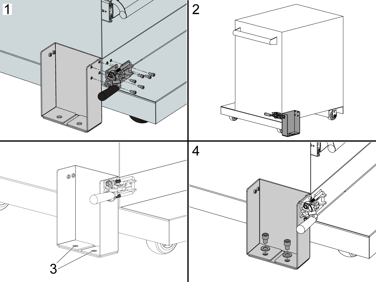
Sheet Metal Anchor Bracket Installation

These instructions are used for installing sheet metal anchor brackets or fence posts for APLs or Haas Robot Packages.

Note: There is no anchor template included with these assemblies. The brackets and fence post anchor holes are used to create the anchor hole locations. The locations are dimensioned in the layouts of the install instructions.

1. Install the Latch Toggle Clamp to the front of the Robot Drawer Cart and Sheet Metal Anchor Bracket.

2. Install the Latch Toggle Clamp to the rear of the Robot Drawer Cart and Sheet Metal Anchor Bracket.

3. The Sheet Metal Anchor Bracket or Fence Post holes are used to mark the drop in anchor hole locations.

4. Install the anchor hardware after the anchors are installed using the Drill Holes and Set the Anchors instructions above.

Recently Viewed Items

You Have No Recently Viewed Items Yet

Feedback
Haas Logo

Haas pris inkl. frakt

I detta pris ingår frakt, export- och tullavgifter, försäkring och övriga kostnader som uppstår för leverans till överenskommen plats. Inga övriga obligatoriska kostnader kan läggas till för leverans av Haas CNC-produkt.

HÅLL DIG UPPDATERAD OM TIPS OCH TEKNIK FRÅN HAAS ...

Anmäl dig nu!   

HAAS TOOLING ACCEPTERAR FÖLJANDE:

  • Service och support
  • Ägare
  • Beställ service
  • Bruksanvisningar
  • Haas reservdelar
  • Reparationsförfrågan, rundmatningsbord
  • Förinstallationsguider
  • Köpa verktyg
  • Bygg och prissätt en ny Haas
  • Tillgänglig inventorie
  • Haas prislista
  • CNCA-finansiering
  • Om Haas
  • Tillgänglighetsmeddelande
  • DNSH-meddelande
  • Exportöverensstämmelse
  • Karriär
  • Certifieringar och säkerhet
  • Kontakta oss
  • Historik
  • Villkor och bestämmelser
  • Villkor och bestämmelser för Haas verktyg
  • Integritet
  • Garanti
  • Haas Community
  • Haas certifieringsprogram
  • Haas Motorsport
  • Gene Haas Foundation
  • Haas gemenskap för teknisk utbildning
  • Evenemang
  • Delta i samtalet
  • Facebook
  • X
  • Flickr
  • YouTube
  • LinkedIn
  • Instagram
  • TikTok
© 2026 Haas Automation, Inc – CNC-verktygsmaskiner

This site is protected by reCAPTCHA and the Google Privacy Policy and Terms of Service apply.

2800 Sturgis Rd., Oxnard, CA 93030 / Toll Free: 800-331-6746
Phone: 805-278-1800 / Fax: 805-278-2255