My Haas Bienvenue,
!
Haas Tooling MyHaas/HaasConnect Se connecter S’inscrire Haas Tooling MyHaas/HaasConnect Se déconnecter Bienvenue, Mes machines Dernière activité Mes devis Mon compte Mes utilisateurs Se déconnecter
Trouver votre distributeur
  1. Sélectionner la langue
    1. English
    2. Deutsch
    3. Español - ES
    4. Español - MX
    5. Français
    6. Italiano
    7. Português
    8. Český
    9. Dansk
    10. Nederlands
    11. Magyar
    12. Polski
    13. Svenska
    14. Türkçe
    15. 中文
    16. Suomi
    17. Norsk
    18. الإنجليزية
    19. български
    20. Hrvatski
    21. Ελληνικά
    22. Română
    23. Slovenský
    24. Slovenščina
    25. 한국어
    26. 日本語
    27. Українська
  • machines Menu principal
    • Fraiseuses verticales
      Fraiseuses verticales
      Fraiseuses verticales Afficher tout
      • Fraiseuses verticales
      • Série VF
      • Machines universelles
      • Série VR
      • Machine à prismes VP-5
      • Centres d’usinage à broche verticale avec changeur de palettes
      • Mini Mills
      • Machines pour l'industrie du moule
      • Centres de perçage à grande vitesse
      • Série perçage-taraudage-fraisage
      • Fraiseuses d’atelier verticales
      • Pocket Mill
      • Fraiseuses compactes
      • Série Portique
      • Détoureuses de plaques SR
      • CUV Extra-Large
      • Fraiseuses colonne double
      • Machines 3+2 axes
    • Solutions multi-axes
      Solutions multi-axes
      Solutions multi-axes Afficher tout
      • Solutions multi-axes
      • Tours à axe Y
      • Fraiseuses à 5 axes
    • Tours
      Tours
      Tours Afficher tout
      • Tours
      • Série ST
      • Double-broche
      • Série à glissières prismatiques
      • Tours d’outilleur
      • Tour à décolleter
      • Tour de poche
      • Ravitailleurs de barres Haas
    • Fraiseuses horizontales
      Fraiseuses horizontales
      Fraiseuses horizontales Afficher tout
      • Fraiseuses horizontales
      • Cône 50
      • Cône 40
    • Tables rotatives et diviseurs
      Tables rotatives et diviseurs
      Tables rotatives et diviseurs Afficher tout
      • Tables rotatives et diviseurs
      • Tables rotatives
      • Diviseurs
      • Produits rotatifs à 5 axes
      • Diviseurs extra-larges
    • Systèmes d’automatisation
      Systèmes d’automatisation
      Systèmes d’automatisation Afficher tout
      • Systèmes d’automatisation
      • Automatisation de fraiseuse
      • Tour et automatisation
      • Chargeurs automatiques de pièces
      • Modèles d’automatisation
    • Machines de bureau
      Machines de bureau
      Machines de bureau Afficher tout
      • Machines de bureau
      • Fraiseuse de bureau
      • Tour de bureau
      • Simulateur de commande, standard
      • Simulateur de commande, Premium
    • Équipement d’atelier
      Équipement d’atelier
      Équipement d’atelier Afficher tout
      • Équipement d’atelier
      • Fraiseuse à console
      • Tours manuels Haas
      • Scies Haas
    • Machines de fabrication
      Machines de fabrication
      Machines de fabrication Afficher tout
      • Machines de fabrication
      • Machine de découpe à laser
      • Presses plieuses CNC
    • LIENS RAPIDES Séries spéciales  Séries spéciales 
      SÉRIE UE SÉRIE UE CONFIGURATION ET PRIX | LISTE DE PRIX CONFIGURATION ET PRIX | LISTE DE PRIX Les nouvelles machines en stock Les nouvelles machines en stock NOUVEAUTÉS NOUVEAUTÉS VOTRE PREMIER CNC VOTRE PREMIER CNC
      OUTILS D'ACHAT
      • Configuration et Prix d’une machine Haas
      • Liste des tarifs
      • Stock disponible
      • Financement CNCA
      VOUS SOUHAITEZ PARLER À UN AGENT ?

      Un magasin d’usine Haas (HFO) peut répondre à vos questions et vous présenter les meilleures options.

      CONTACT YOUR DISTRIBUTOR >
  • Options Menu principal
    • The Haas Control Les Packs d’options Plus
      Les Packs d’options Plus
      Les Packs d’options Plus Afficher tout
      • Les Packs d’options Plus
    • Product Image Broche
      Broche
      Broche Afficher tout
      • Broche
    • Product Image Changeurs d’outils
      Changeurs d’outils
      Changeurs d’outils Afficher tout
      • Changeurs d’outils
    • Product Image 4e et 5e axes
      4e et 5e axes
      4e et 5e axes Afficher tout
      • 4e et 5e axes
    • Product Image Tourelles et outil Tournant
      Tourelles et outil Tournant
      Tourelles et outil Tournant Afficher tout
      • Tourelles et outil Tournant
    • Product Image Palpage
      Palpage
      Palpage Afficher tout
      • Palpage
    • Gestion des copeaux et du liquide de coupe Haas Gestion des copeaux et du liquide de coupe
      Gestion des copeaux et du liquide de coupe
      Gestion des copeaux et du liquide de coupe Afficher tout
      • Gestion des copeaux et du liquide de coupe
    • La commande Haas La commande Haas
      La commande Haas
      La commande Haas Afficher tout
      • La commande Haas
    • Product Image Options de produit
      Options de produit
      Options de produit Afficher tout
      • Options de produit
    • Product Image Outillage et montages d’outillages de fixation
      Outillage et montages d’outillages de fixation
      Outillage et montages d’outillages de fixation Afficher tout
      • Outillage et montages d’outillages de fixation
    • Product Image Dispositifs de serrage de pièces
      Dispositifs de serrage de pièces
      Dispositifs de serrage de pièces Afficher tout
      • Dispositifs de serrage de pièces
    • Product Image Solutions à 5 axes
      Solutions à 5 axes
      Solutions à 5 axes Afficher tout
      • Solutions à 5 axes
      • 5 Easy Steps to 5-Axis
    • Product Image Automatisation
      Automatisation
      Automatisation Afficher tout
      • Automatisation
    • LIENS RAPIDES Séries spéciales  Séries spéciales 
      SÉRIE UE SÉRIE UE CONFIGURATION ET PRIX | LISTE DE PRIX CONFIGURATION ET PRIX | LISTE DE PRIX Les nouvelles machines en stock Les nouvelles machines en stock NOUVEAUTÉS NOUVEAUTÉS VOTRE PREMIER CNC VOTRE PREMIER CNC
      OUTILS D'ACHAT
      • Configuration et Prix d’une machine Haas
      • Liste des tarifs
      • Stock disponible
      • Financement CNCA
      VOUS SOUHAITEZ PARLER À UN AGENT ?

      Un magasin d’usine Haas (HFO) peut répondre à vos questions et vous présenter les meilleures options.

      CONTACT YOUR DISTRIBUTOR >
  • Why Haas Menu principal
      Découvrez la différence Haas
    • Pourquoi Haas
    • MyHaas
    • Communauté éducative
    • Industrie 4.0
    • Certification Haas
    • Témoignages émanant de clients
  • Service Menu principal
      Bienvenue au Haas Service
      SERVICE - ACCUEIL Manuels opérateur Procédures détaillées Guides de dépannage Maintenance préventive Pièces Haas Haas Tooling Vidéos
  • Vidéos Menu principal
  • Outillage Haas Menu principal
My Haas Bienvenue,
!
Haas Tooling MyHaas/HaasConnect Se connecter S’inscrire Haas Tooling MyHaas/HaasConnect Se déconnecter Bienvenue, Mes machines Dernière activité Mes devis Mon compte Mes utilisateurs Se déconnecter
Trouver votre distributeur
  1. Sélectionner la langue
    1. English
    2. Deutsch
    3. Español - ES
    4. Español - MX
    5. Français
    6. Italiano
    7. Português
    8. Český
    9. Dansk
    10. Nederlands
    11. Magyar
    12. Polski
    13. Svenska
    14. Türkçe
    15. 中文
    16. Suomi
    17. Norsk
    18. الإنجليزية
    19. български
    20. Hrvatski
    21. Ελληνικά
    22. Română
    23. Slovenský
    24. Slovenščina
    25. 한국어
    26. 日本語
    27. Українська
×

Résultats de la recherche

Web Pages

Images

    • <
    • 1
    • >

3 - MM / SMM - Installation

MiniMill / Super Minimill - Interactif - Manuel d'entretien


  • 0 - MM/SMM - Table des matières
  • 1 - MM / SMM - Introduction
  • 2 - MM / SMM - Spécifications
  • 3 - MM / SMM - Installation
  • 4 - MM/SMM - Changeur d’outils de type parapluie
  • 5 - MM / SMM - SMTC
  • 6 - MM / SMM - Déplacement d'axe
  • 7 - MM / SMM - Broche
  • 8 - MM / SMM - Moteur de broche
  • 9 - MM / SMM - Systèmes de lubrification
  • 10 - MM / SMM - Commande électrique
  • 11 - MM / SMM - Évacuation des copeaux et du liquide de coupe
  • 12 - MM / SMM - Dispositif de serrage de la pièce
  • 13 - MM / SMM - Entretien
  • 14 - MM / SMM - Porte automatique et fenêtre automatique
  • 15 - MM / SMM - Robot et automatisation
  • 16 - MM / SMM - Cartérisation

Go To :

  • 3.1 Installation MM/SMM
  • 3.2 Redémarrer l'installation MM/SMM
  • 3.3 Ancrage

3.1 MM/SMM – Installation

Recently Updated

Mini Mill/Super Mini Mill - Installation


Introduction

Cette procédure vous indique comment installerun Mini Mill/2/EDU, ou Super Mini Mill/2. Pour installer un Mini Mill à redémarrage, consultez la procédure  Mini Mill – Installation en savoir plus.

Pour déterminer quel type de version Mini Mill vous avez, consultez le document de

  référence Mini Mill/Super Mini Mill - Version machine - Identification.

Outils requis :

  • 3/4" prise
  • 5/32", 1/4", 3/8" Sockets Hex Bit
  • cliquet
  • 3/4", 1,5" clé à molette
  • mètre
  • 0,0005" ou 1 micron Test Indicator and Magnetic Base
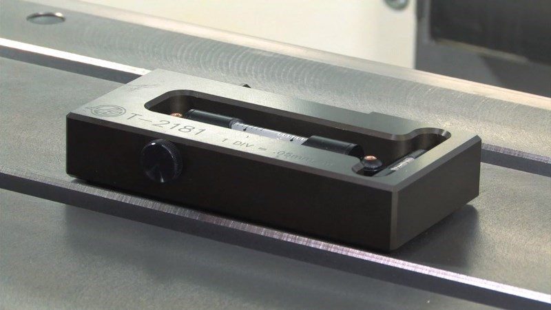
  • T-2181 SERVICE TOOL, LEVELING TOOL ou Precision Machinist Level, 0,0005" division

Leveling Screws Hardware

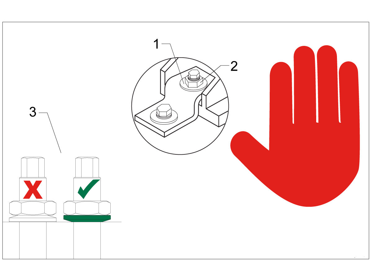
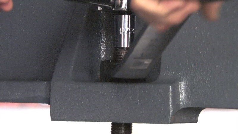
Note: The washers [1] and nuts [2] are installed during shipping and should be saved for installation and not be discarded.

Note: The washer orientation [3] is important.  The conical part of the washer should be against the casting,  see illustration.

Remove Rust Inhibitor

To safely and effectively remove rust inhibitor from way covers and other non-painted surfaces:

Initial Scraping

  • Use a plastic scraper to remove the bulk of the rust inhibitor.
  • Avoid using metal tools to prevent scratching or damaging the surface.

 Important: Do not use scotch-brite or metal scrapers, these will scratch the way covers.

Chemical Cleaning

  • Spray the affected areas with a heavy-duty citrus cleaner or Simple Green.
  • Ensure full coverage of all non-painted surfaces coated with rust inhibitor.

Soak Time

  • Allow the cleaner to soak for several minutes to loosen remaining residue.

Wipe Down

  • Use a clean shop towel to thoroughly wipe off the softened rust inhibitor.

Rust Proofing

  • Apply mineral spirits or WD-40 to all exposed metal surfaces to prevent future rust formation.

Important: Always wear gloves and eye protection when handling chemical cleaners. Dispose of used towels and cleaning agents according to local environmental regulations.

 Important: To avoid any contamination of the way cover seals with the sticky residue. Do not move any of the axes until all the rust inhibitor has been removed.

Rust Inhibitor - Safety Data Sheet (SDS)

Air Connection

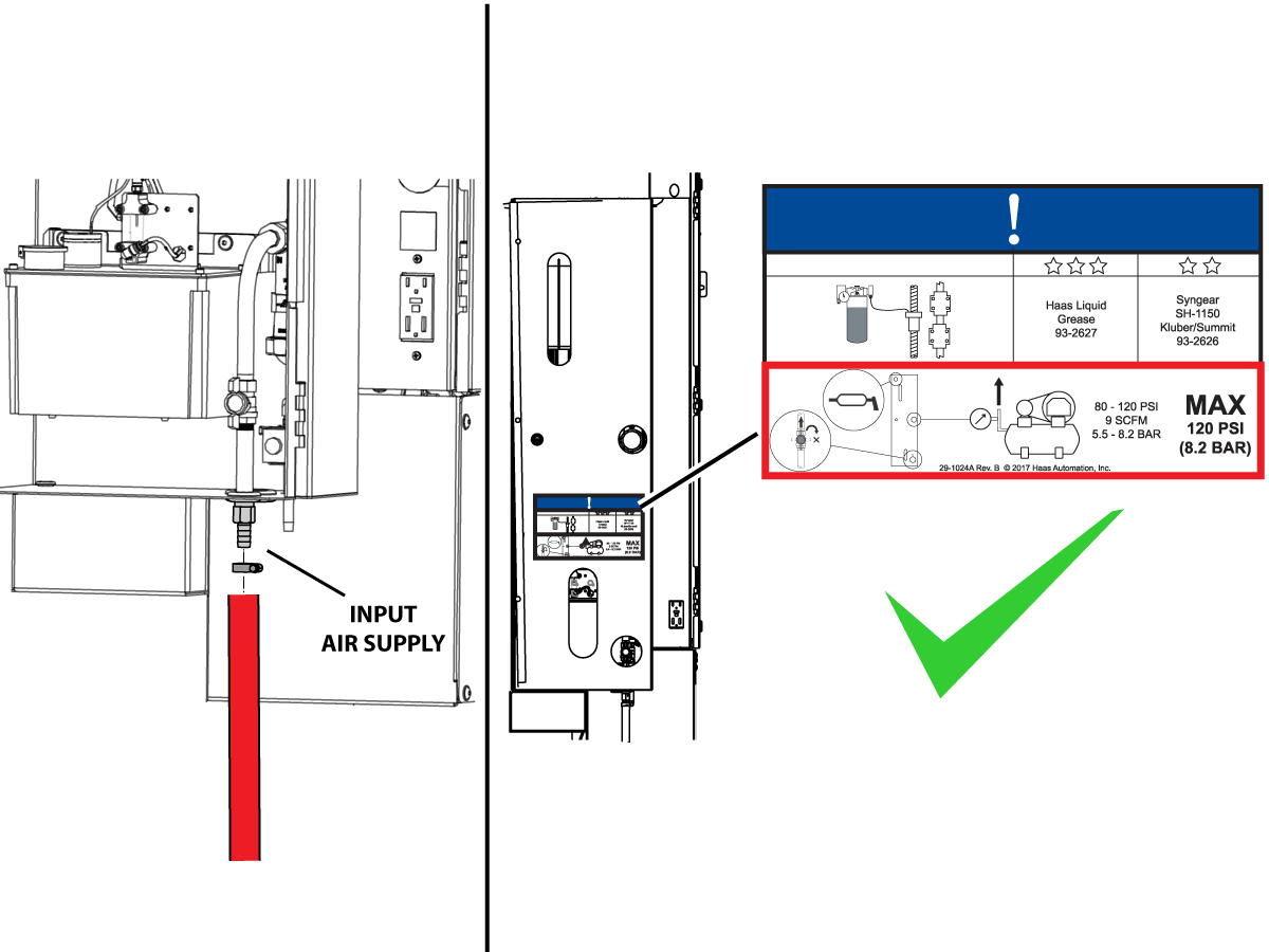
Connect the air supply at the lube panel.

 Note: For air requirements refer to the decal that is located on the lube cabinet door.

Follow the Air Gun and Hose Installation procedure to install or replace the Air Gun.

 Note: Some installation kits will come with a spare air gun assembly.

Electrical Installation

 DANGER: Working with the electrical services required for CNC machines is extremely hazardous and can result in serious injury or death.

Before connecting line wires to the CNC:

  • Turn off all power to the machine at the source.
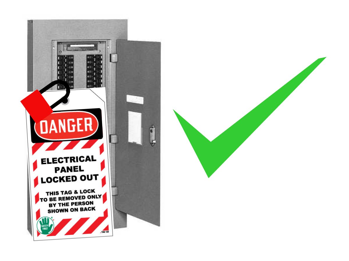
  • Perform a Lockout-Tagout (LOTO) procedure to ensure the power remains off during service.
  • Verify that power has been disconnected by using an AC voltage detector on all incoming lines.

If you are uncertain about how to safely disconnect power or perform LOTO procedures:

  • Do not proceed.
  • Contact qualified personnel or obtain appropriate assistance before continuing.

Failure to follow these precautions may result in electrical shock, equipment damage, or fatal injury.

1

Initial Control Inspection

Danger: At this point, there should be no electrical connection to the machine. Electrical panel must be closed and secured. When main switch is on, there is HIGH VOLTAGE throughout the electrical panel (including the circuit boards and logic circuits) and some components operate at high temperatures. Therefore, exercise extreme caution when working in the panel.

  • Set the main breaker switch at the upper right of the electrical panel on the back of the machine to OFF.
  • Using a screwdriver, unlock the two latches on the panel door, unlock the cabinet with the key and open the door.
  • Take sufficient time to check all the components and connectors associated with the circuit boards. Look for any cables that have become disconnected, look for any signs damage and loose parts in the bottom of the panel box. If there are any signs that the machine was mishandled, call the factory before proceeding.

2

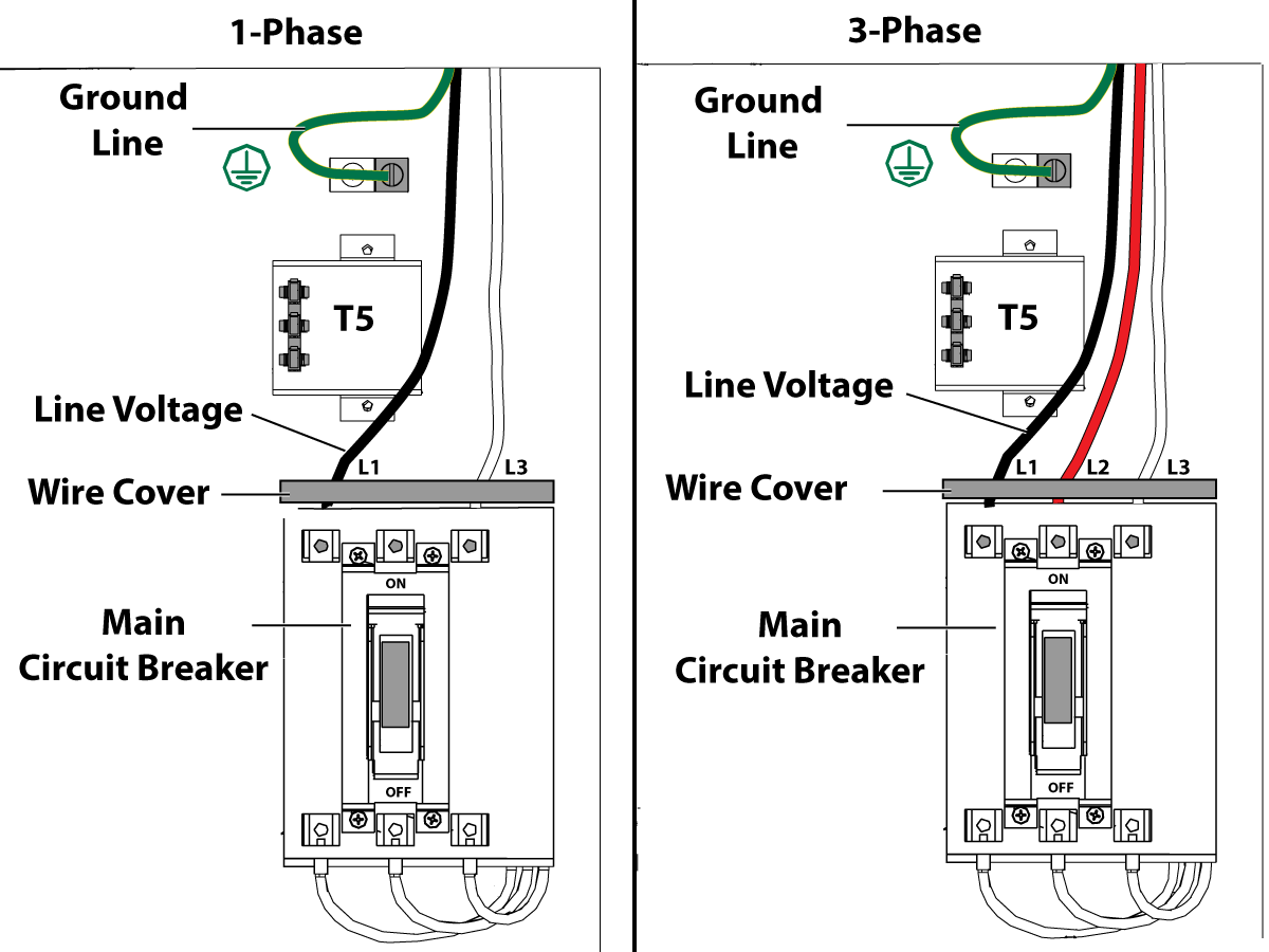
1-Phase Machines: Insert each power lead into the wire cover.  Connect the two power leads to L1 and L3 terminals on top of the main circuit breaker.

3-Phase Machines: Insert each power lead into the wire cover.  Connect the three power leads to L1, L2 and L3 terminals on top of the main circuit breaker.

Connect the separate ground line to the ground bus to the left of the terminals.

For 3-phase machines, check to see what type of power configuration is supplying the machine. Take voltage measurements of each power lead to ground line. Then refer to RD0084 - Input Power Configurations to determine which power lead should be connected to the L1 terminal based of the voltage readings and power configuration.

Refer to Haas Main Circuit Breaker - Torque Specifications for what value to torque the circuit breaker power leads.

 Note: Make sure that the leads actually go into the terminal-block clamps . (A poor connection will cause the machine to run intermittently or have other problems, such as servo overloads.) To check, simply pull on the wires after the screws are tightened.

3

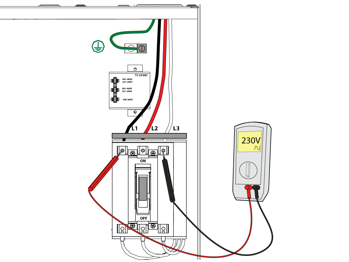
After the line voltage is connected to the machine, make sure that main circuit breaker (at top-right of rear cabinet) is OFF . Remove the Lockout / Tagout and Turn ON the power at the source. Using a digital voltmeter and appropriate safety procedures: 

1-Phase Machines: Measure the AC voltage across L1 & L3 at the main circuit breaker.  The AC voltage must be between 220 - 250 volts .
Note: Lower or higher than this voltage can generate low/high voltage alarms.

3-Phase Machines : Measure the AC voltage between all three pair phases at the main circuit breaker. 

The AC voltage must be between 195 and 260 volts (360 and 480 volts for high voltage option).

SMinimill - Reboot: The AC voltage must be between 198 and 242 volts for machines without a high voltage transformer.  Refer to the Minimill/SMinimill - Identification document.

 Note: Wide voltage fluctuations are common in many industrial areas; minimum and maximum voltage supplied to a machine while it is in operation must be known. U.S. National Electrical Code specifies that machines should operate with a variation of +5% to -5% around an average supply voltage. If problems with line voltage occur, or low line voltage is suspected, an external transformer may be used. If you suspect voltage problems, voltage should be checked every hour or two during a typical day to be sure it does not fluctuate more than +5% or -5% from an average.

4

Important: With the main circuit breaker turned OFF.

Check the transformer taps at the bottom-right corner of the rear cabinet.

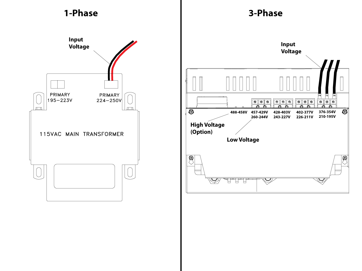
1-Phase Machines: The input voltage cable must be moved to the connector which corresponds to the average voltage measured in the above step.

3-Phase Machines:  The input voltage cables labeled 74, 75, and 76 must be moved to the terminal block triple which corresponds to the average voltage measured in the above step.

5

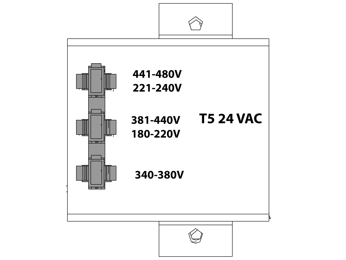
Transformer T5 supplies 24VAC used to power the main contactor. There are two versions of this transformer for use on a 240 and 400V machines. The 240V transformer has two input connectors located about two inches from the transformer, which allow it to be connected to either 180-220V or 221-240V.

Users that have 220V-240V RMS input power should use the connector labeled 221-240V, while users with 190-220V input power should use the connector labeled 180-220V. Failure to use the correct input connector will result in either overheating of the main contactor or failure to reliably engage the main contactor.

The 480V (option) T5 transformer has three input connectors, labeled 340-380V, 381-440V and 441-480V.

Users with 340-380V 50/60Hz power should use the 340-380V connector while users with 380V-440V 50/60Hz power should use the 381-440V connector.

Important: Set the main circuit breaker to ON. Check for evidence of problems, such as the smell of overheating components or smoke. If such problems are indicated, immediately set the main circuit breaker to OFF and call the factory before proceeding.

After the power is on, measure the voltage across the bottom terminals on the main circuit breaker. It should be the same as the measurements where the input power connects to the main breaker. If there are any problems, check the wiring.

6

Apply power to the control by pressing the Power-On switch on the front panel.

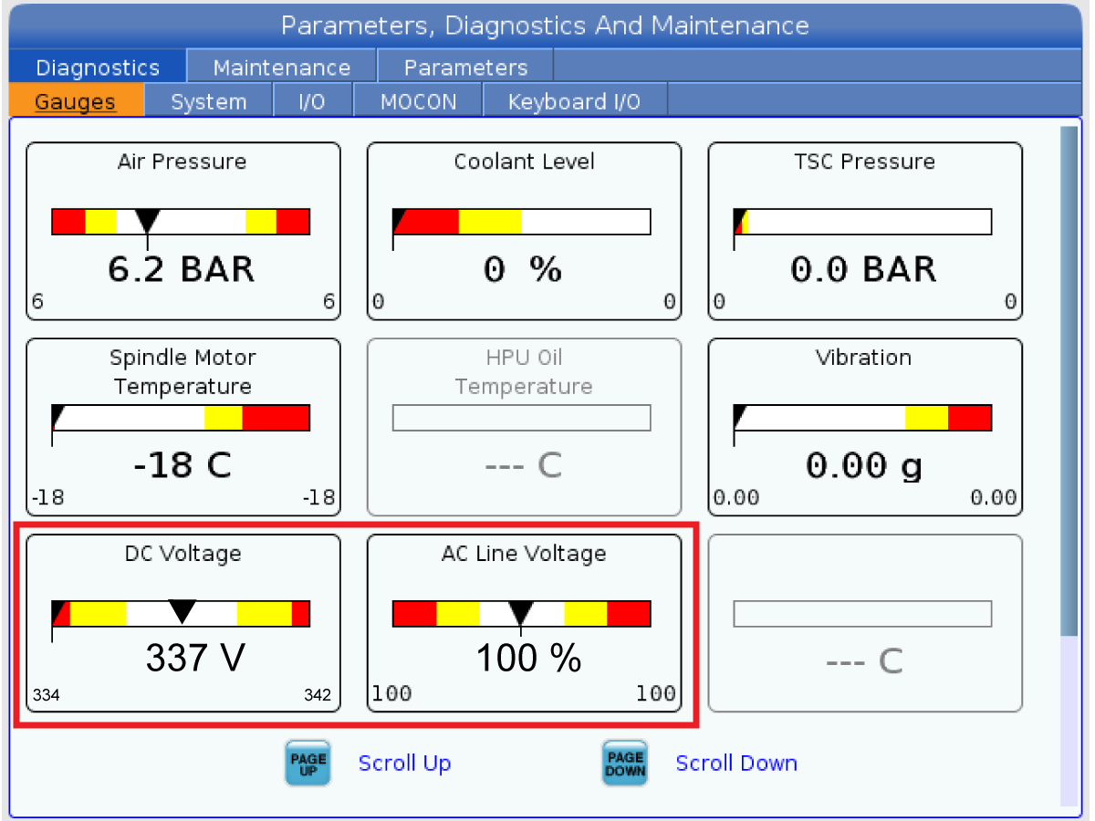
Check the DC Voltage and AC Line Voltage gauges in Diagnostics. The DC Voltage gauge must read between 310 - 360V. The AC Line Voltage must be between 90 and 105 percent. If the voltage is outside these limits, turn off the power and recheck steps 2 and 3. If the voltage is still outside these limits, call the factory.

7

Electrical power must be phased properly to avoid damage to your equipment. The Power Supply Assembly PC board incorporates a "Phase Detect" circuit with neon indicators. When the orange neon is lit (NE5), the phasing is incorrect. If the green neon is lit (NE6), the phasing is correct. If both neon indicators are lit, you have a loose wire; check the connections. Adjust phasing by setting the source power to off and then swapping L1 and L2 of the incoming power lines at the main circuit breaker.

Danger: ALL POWER TO CNC MUST BE TURNED OFF LOCKOUT-TAGOUT AT THE SOURCE PRIOR TO ADJUSTING PHASING. ALWAYS DOUBLE CHECK THE INCOMING LINES WITH AN AC VOLTAGE DETECTOR.

Turn off the power and set the main circuit breaker to OFF. Close the door, lock the latches, and turn the power back on.

Remove the key from the control cabinet and give it to the shop manager.

8

Activation

When the machine is properly placed and connected to both air and electrical power, it is ready for final installation (removing shipping blocks, leveling, spindle sweep, etc.) and software activation. The HFO service technician does this. Contact the local HFO to schedule the work.

IMPORTANT:  Machines equipped with motion sensors must be rough‑leveled before attempting to arm the motion sensor.  For detailed instructions, refer to Service Notification - SA0007.  Access to this document is restricted to Haas Factory Outlet personnel.

Shipping Brackets Removal

1

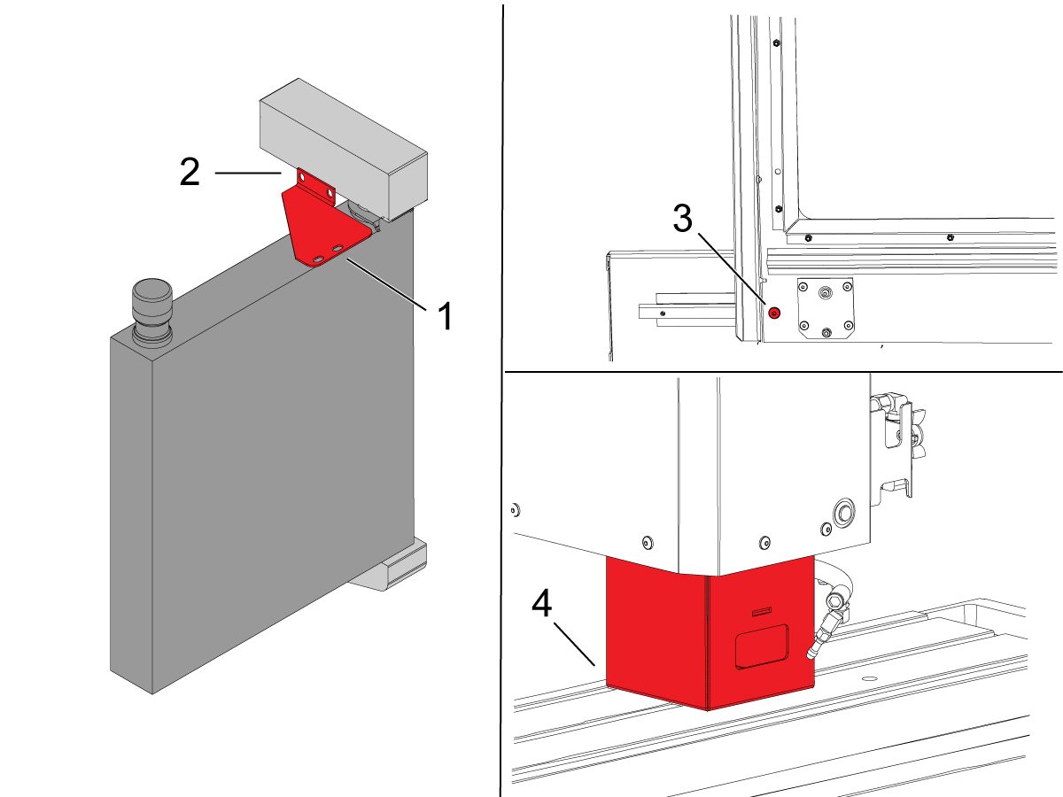
Retirez le support d'expédition du boîtier de commande.

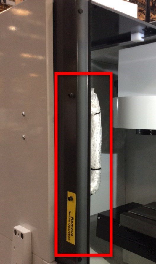
2

Enlevez le support pour le transport de la petite porte de l’opérateur.

3

Remontez la poignée de porte à l'extérieur de la porte de l'opérateur.

4

appuyer sur [POWER ON] et suivez les instructions indiquées à l'écran.

Appuyez sur les boutons [HAND JOG] et [Z+] . Déplacez l'axe Z vers le haut.

Retirez le support d’expédition de la broche 40T.

Machine Leveling

1

Faites un retour à l’origine de chaque axe un à la fois ou appuyez sur  [POWER UP]. Passez par le processus de nivellement.
Répétez ces étapes pour atteindre le niveau correct de la machine.

2

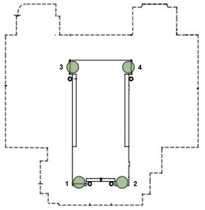
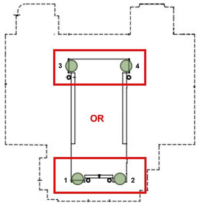
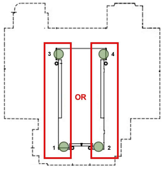
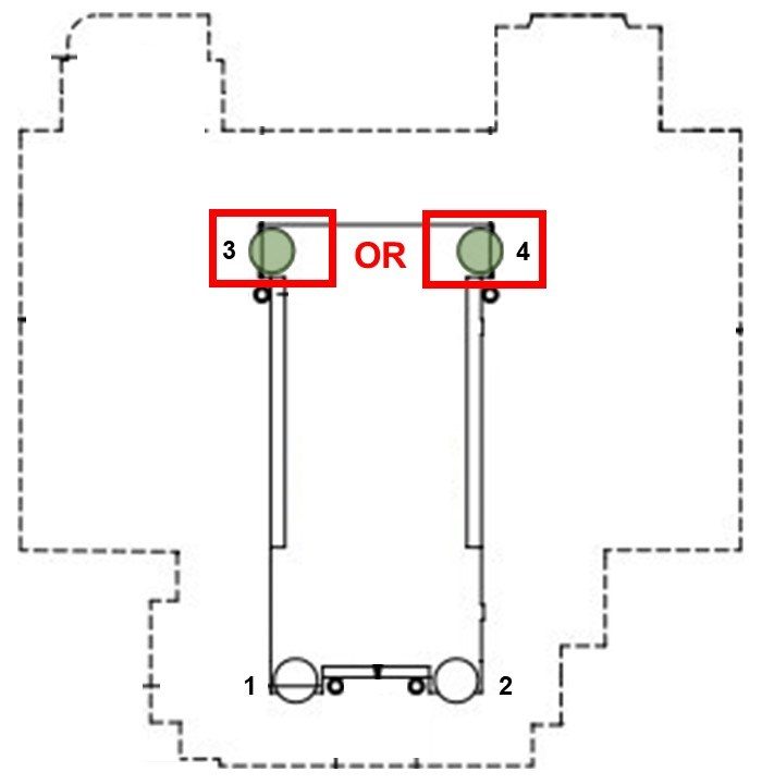
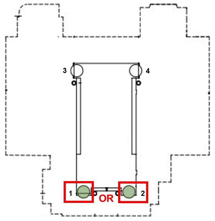
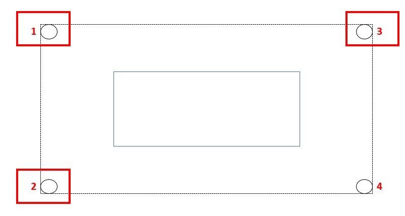
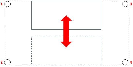
Définir la hauteur de la machine à l'aide des quatre boulons de nivellement d'angle [1 ,2, 3, 4] à 3" +/- 0,5" (75 mm +/- 10 mm) au-dessus du sol. Tournez chaque vis pour qu'ils aient une tension égale.

Déplacez l'axe X et Y au milieu de leur course, en centrant la table.

note: L’image montre la disposition du DM-2, mais le même processus s'applique à toutes les machines DM, DT, Mini Mill et Super Mini Mill avec quatre boulons de mise à niveau. Si votre machine a six boulons de nivellement ou plus, veuillez consulter :

Nivellement CUV

3

Nettoyez la surface de la table et l'outil de nivellement (T-2181) et vérifiez l'étalonnage de l'outil de nivellement avant de procéder.

Placez le niveau au centre de la palette, parallèlement à l'axe X.  Utilisez une rainure en t pour l'alignement.

Notez la position de la bulle.

Repositionner le niveau en le tournant à 180 degrés. La bulle doit afficher la même lecture qu'auparavant.

Si les lectures sont différentes par plus d'une division, retournez le niveau à Haas pour l'ajustement et ne l'utilisez pas pour niveler la machine.

4

Ajuster les boulons de nivellement des coins [1, 2] ou [3, 4] jusqu'à ce que la bulle parallèle à l'axe Y soit centrée.

Cela nivele la machine d'avant en arrière.

Soulevez toujours le côté inférieur de la machine pour maintenir le dégagement pour le réservoir de refroidissement (s'il est équipé) et ajustez les deux boulons de nivellement de ce côté une quantité égale.

5

Ajuster les boulons de nivellement des virages [1, 3] ou [2, 4] jusqu'à ce que la bulle parallèle à l'axe X soit centrée.

Cela nivele la machine de gauche à droite.

Encore une fois, soulevez le côté inférieur de la machine et ajustez les deux boulons de nivellement de ce côté une quantité égale.

6

Gardez le niveau dans la même position et faites avancer l'axe Y pour amener la table à l'avant de la machine.

Notez la position de la bulle.

Déplacez l'axe Y sur l’ensemble de la course, s'arrêtant à la colonne. Regardez pour voir quel coin arrière de la machine est le plus bas, comme le montre l'outil de nivellement.

Soulevez le coin arrière le plus bas en ajustant le boulon de nivellement d'angle [3] ou [4] jusqu'à ce que la bulle soit centrée sur le niveau.

7

Déplacez l'axe Y de retour à travers l’ensemble de sa course, apportant la table à l'avant de la machine. Regardez pour voir quel coin avant est le plus bas, comme le montre le niveau.

Soulevez le coin avant le plus bas en ajustant le boulon de nivellement d'angle [1] ou [2] jusqu'à ce que la bulle soit centrée sur le niveau.

Répétez les étapes 6 et 7, en déplaçant la table d'avant en arrière à travers l’ensemble de la course de l'axe Y, soulevant le coin le plus bas à chaque fois.

Poursuivez ce processus jusqu'à ce que le niveau indique zéro aux deux extrémités de la course de l'axe Y.

Spindle Sweep Check

1

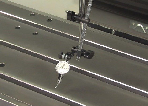
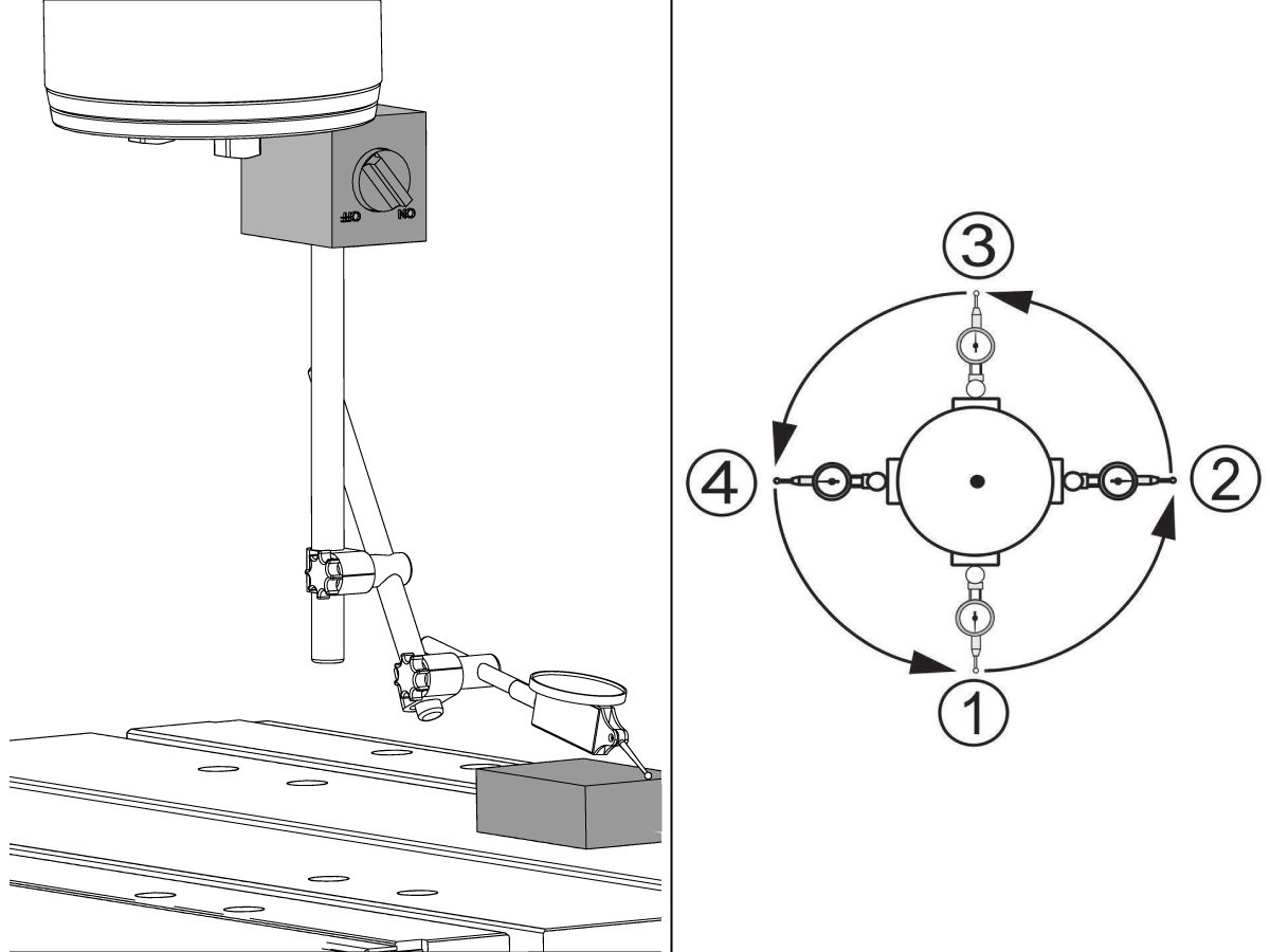
Abaissez l’axe Z au milieu de sa course. Fixez l'indicateur d'essai à la base magnétique et attachez la base magnétique au fond de la broche.

Positionner l'indicateur d'essai pour mesurer un 10" (250mm) de diamètre cercle au centre de la table.

Placez la table de sorte que l'indicateur d'essai reste sur la table (pas sur une rainure en t) lorsque vous êtes face à l'avant et les côtés de colonne de la machine.

Face à l'indicateur vers l'avant de la machine, abaisser l'axe Z en dixième (0,0001") incréments, et amenez l'indicateur de test vers le bas pour contacter le tableau.

Zéro l'indicateur.

2

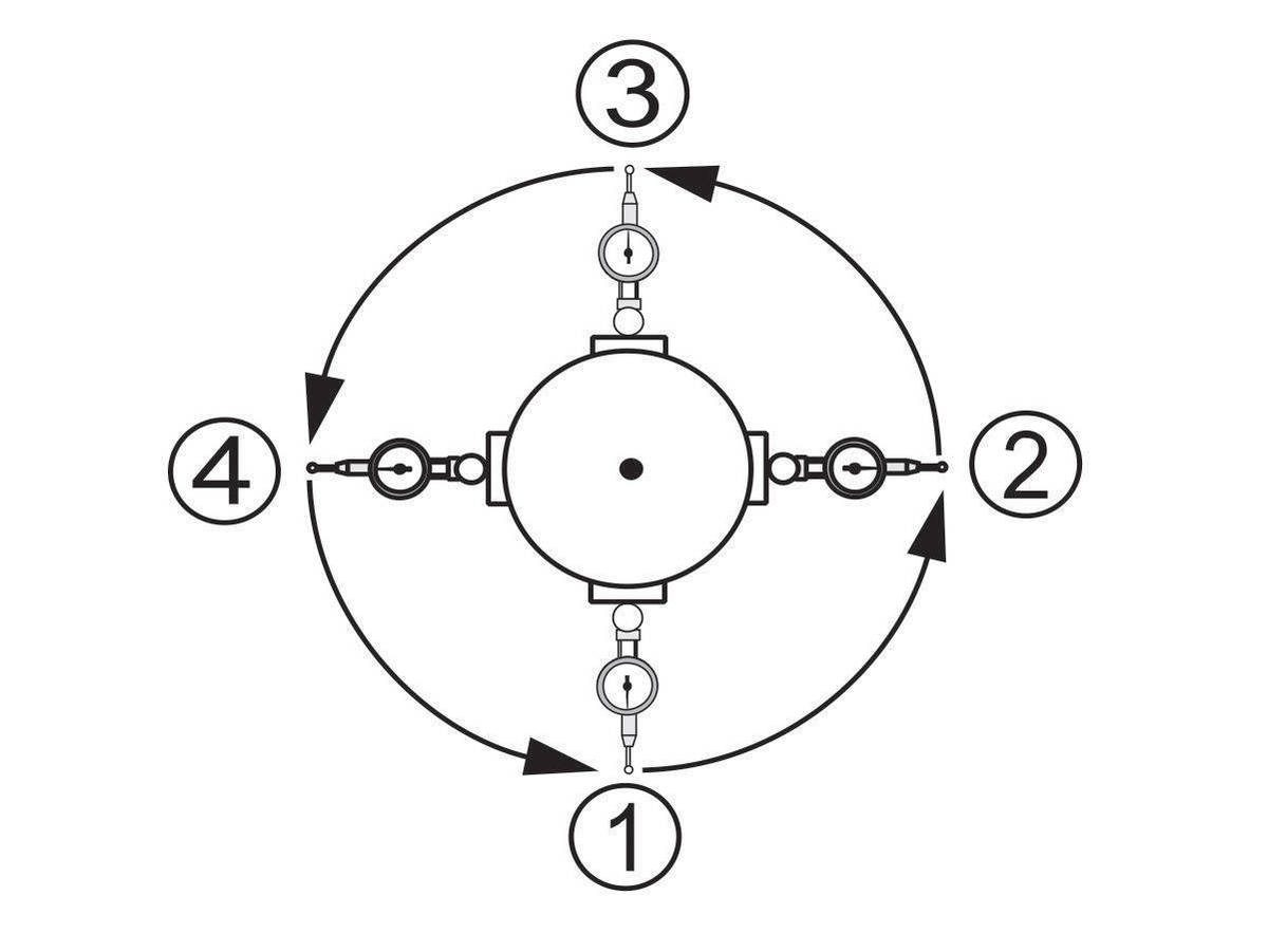
Tournez la broche à la main et prenez une lecture tous les 90 degrés pour fournir deux valeurs le long de l'axe X et y-axe.

La différence entre les lectures d'indicateurs pour chaque axe ne doit pas dépasser 0,0005" (0,013 mm).

3

Verrouillez les boulons de nivellement en place en resserrant l'écrou de verrouillage tout en maintenant le boulon de nivellement.

Assurez-vous que les boulons de nivellement ne bougent pas pendant ce processus.

Si le balayage de broche est hors de tolérance, assurez-vous que le niveau de la machine est correct.

Pour un guide plus approfondi sur la façon d'effectuer cette procédure, veuillez consulter :

Balayage de spindle de CUV

Lubrication Verification

1

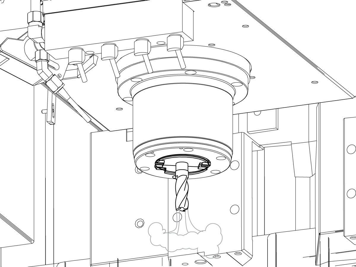
Run the spindle run-in program.

 Note: For 10K spindles and above use a balanced tool holder

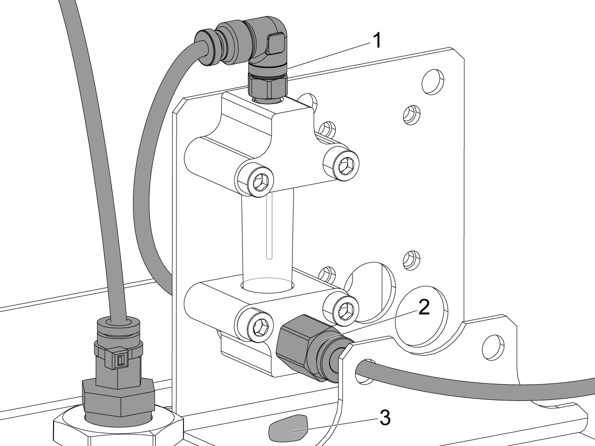
Examine the sight glass, make sure the correct number of drops are fall through the sight glass.

Examine the fittings [1,2] on top of the oil pump tank.

The oil collects on top of the oil pump tank [3] either behind or in front of the sight glass bracket, underneath the leaking fitting.

Tighten any leaking fittings.

2

Go to the Maintenance tab.

Press [F2] to cycle an axis lubrication test.

Inspect the gauge on the lubrication system.  Make sure it holds pressure.

MiniMill-EDU Machines

1

Pour les machines MiniMill-EDU : Si la machine dispose de l’option de réservoir de liquide de coupe de 45 gallons 93-1001072, le séparateur de copeaux et le rail pour liquide de coupe doivent être installés.

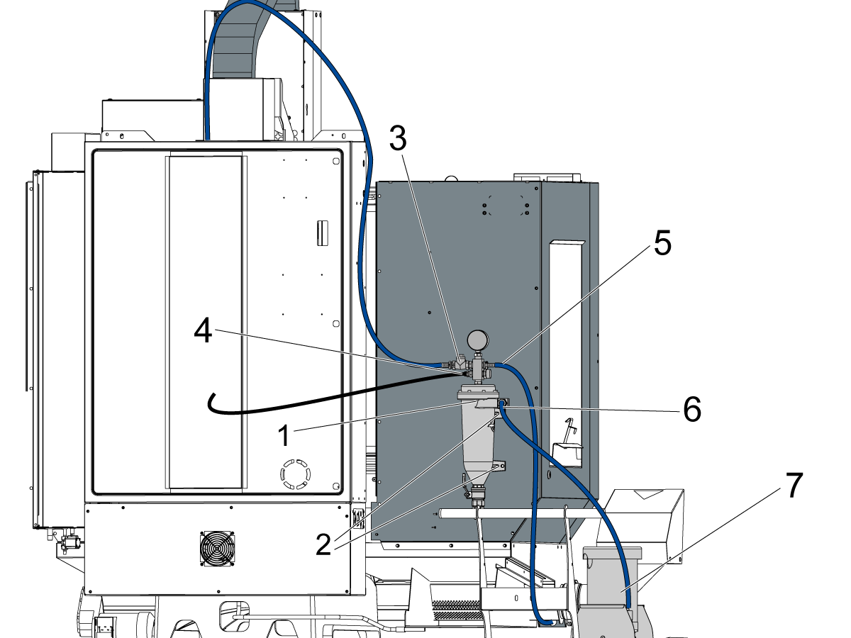
Installez le filtre de liquide de coupe [1] en le fixant à l’arrière du panneau de cartérisation avec le FBHCS [2]. Connectez ensuite les tuyaux et acheminez-les comme indiqué ci-dessous :

Acheminez le tuyau de liquide de coupe bleu [3] du haut à gauche du séparateur de copeaux au raccord dans la tête de broche.

Acheminez la conduite de liquide de coupe noire [4] du raccord push-to-connect au connecteur de lavage du carter télescopique arrière de l’axe Y. Le tuyau doit être acheminé à travers la pièce coulée de la colonne.

Acheminez le tuyau de liquide de coupe bleu [5] du haut à droite de l’assemblage du séparateur de copeaux au support du pistolet de lavage au liquide de coupe.

Connectez le tuyau de liquide de coupe bleu [6] du milieu du séparateur de copeaux à la pompe d’arrosage [7].

2

Pour les machines Minimill-EDU :

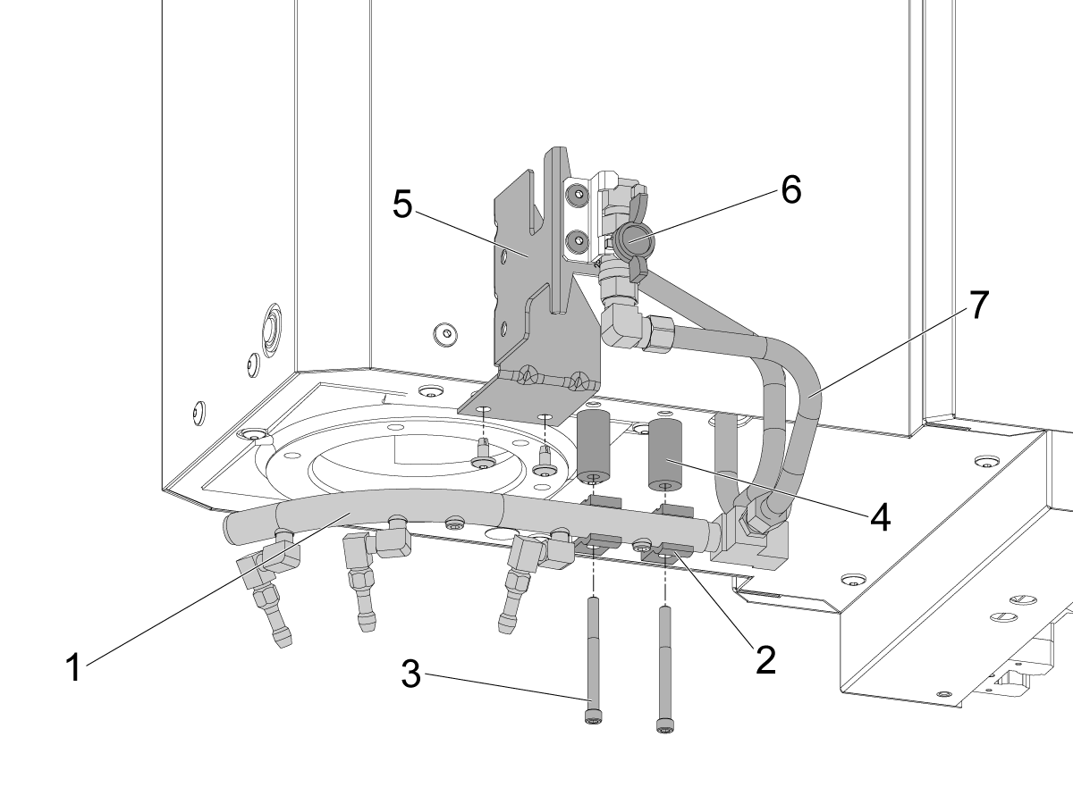
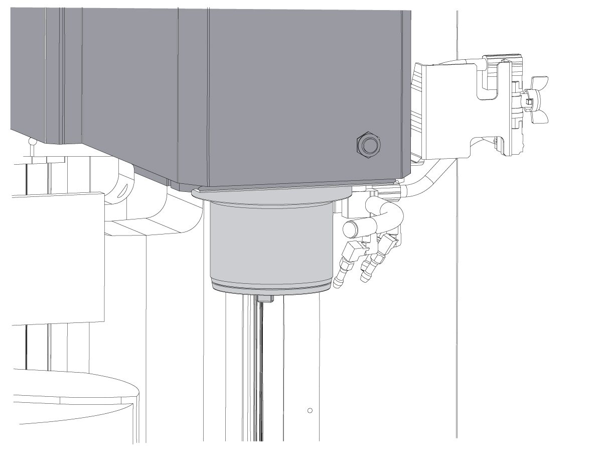
Installez l’assemblage de l’anneau d’arrosage en le fixant à la tête de broche.

Utilisez la vis SHCS longue [3] et les 2 colliers de rail de liquide de coupe [2] pour installer l’assemblage du rail de liquide de coupe [1].

Utilisez les entretoises [4] entre le rail de liquide de coupe et la tête de broche.

Fixez le support de montage P-COOL [5] à la tête de broche à l’aide de la vis BHCS.

Acheminez le tuyau allant de la tête de broche à la soupape de liquide de coupe [6].

Acheminez l’autre tuyau [7] de la vanne au rail de liquide de coupe.

Remarque :assurez-vous que tous les raccords sont serrés pour éviter les fuites de liquide de coupe.

Remarque : Si la machine a été commandée à l’usine avec l’option de liquide de coupe de 45 gallons, ces étapes ne sont pas nécessaires. Elles ne doivent être suivies que pour le kit d’installation sur site 93-1001072. Vérifiez que l’option fonctionne après les tests de la section suivante.

Option Installation Guides

Vérifiez et testez que toutes les options ont été correctement installées.

Manivelle électronique portable (RJH-Touch) - Installation
Option caméra wi-fi – Installation
Pack Tranquillité
Filtre auxiliaire de liquide de coupe
Installation CABCOOL
PulseJet - Installation
Récupérateur d'huile HAAS
Éclairage de table de travail
Soufflage à air comprimé sur outil
Pistolet à air comprimé automatique

Final Testing

1

Connectez la pompe de refroidissement et la pompe de refroidissement à broches (TSC) (si elle est équipée).

Fixez le tuyau de refroidissement bleu de l'entonne de filtre à la prise de pompe de refroidissement.

Branchez la pompe de refroidissement à la prise de refroidissement à basse pression.

Fixez la pompe TSC au petit tuyau de refroidissement violet.

Branchez la pompe TSC à la prise de refroidissement à haute pression.

Branchez le capteur de niveau de refroidissement et d'autres capteurs connexes aux prises correspondantes.

2

Testez le refroidissant d'inondation.

Ouvrez la vanne de l'anneau de liquide de refroidissement et fermez la porte de l'opérateur avant cet essai.

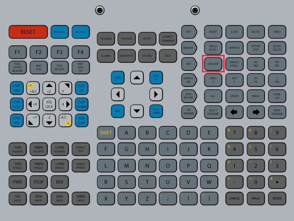
Appuyez [COOLNT] sur la commande. Le liquide de refroidissement devrait être inondé des buses.

appuyer sur [COOLNT] à nouveau pour arrêter le flux.

3

Testez le refroidisseurs à broches (TSC) (s'il est équipé).

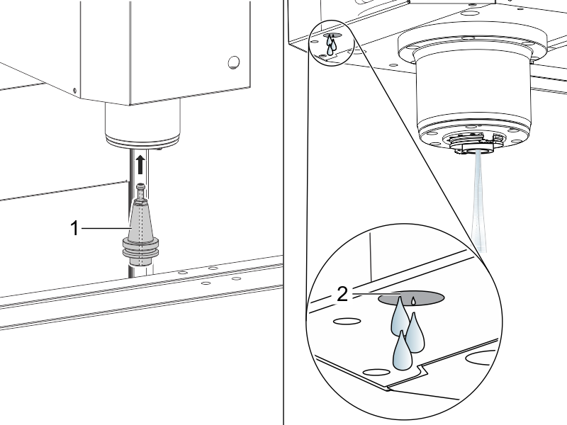
Mettez un porte-outil TSC [1] dans la broche.

appuyer sur [AUX CLNT] pour démarrer le TSC.

Le fonctionnement correct est le suivant :

  1. Le liquide de coupe s'écoule correctement du porte-outil TSC.
  2. Quelques gouttes s'écoulent du tuyau générateur sous vide [2].

Appuyez sur [RESET].

4

Arrêter la broche.

Exécutez le programme de run-in de broche.

Rodage de broche

5

Testez le Chip Auger (s'il est équipé).

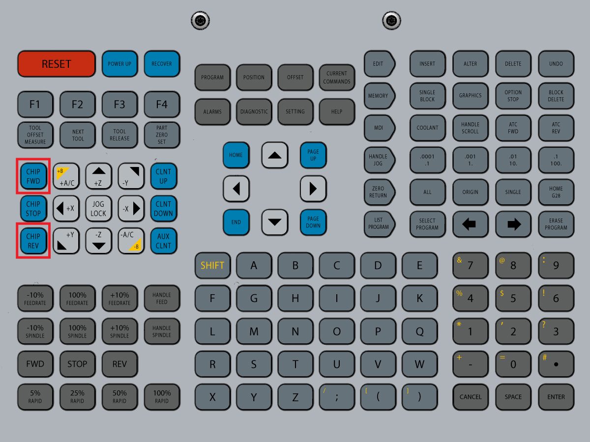
Appuyez sur [CHIP FWD] et [CHIP REV] sur la commande.

6

Testez les verrouillages de porte.

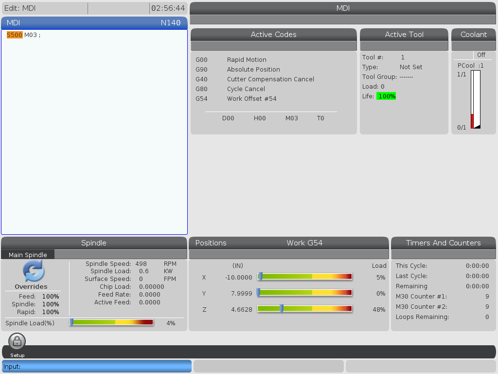
appuyer sur [MDI]entrer S500 M03, et appuyez sur [ENTER].

Assurez-vous que la machine n'est pas en mode de mise en place en vérifiant l'interrupteur de clé sur le côté du boîtier de commande.

appuyer sur [CYCLE START] avec la porte ouverte. La machine devrait dire de fermer la porte et d'appuyer [CYCLE START].

appuyer sur [CYCLE START] avec la porte fermée. La goupille de verrouillage doit s'étendre et la broche devrait commencer à tourner.

Essayez d'ouvrir la porte avec la broche tournante. La broche ne doit pas cesser de tourner.

7

Testez l’arrosage par soufflage à air comprimé (TAB) (s'il est équipé).

Utiliser ce code en mode MDI :

M73;

G04 P5 ;

M74;

G04 P3 ;

M99

M73 démarre la TAB. M74 arrête la TAB.

Actionnez manuellement le TAB :

Appuyez sur [AUX CLNT]. Appuyez sur la touche flèche descendante du curseur  [RIGHT] DOWN.

Le soufflage à air comprimé de l'outil commence.

Appuyez sur [AUX CLNT].

Le soufflage à air comprimé de l'outil s'arrête.

8

Testez les commutateurs de clé.

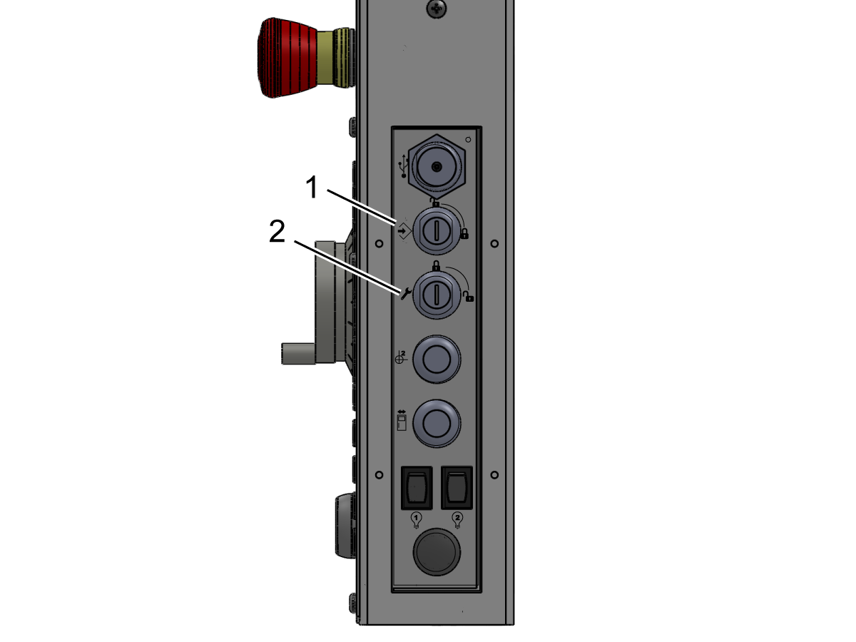
Insérez la clé de verrouillage de configuration/exécution (#2007) à la fente de clé inférieure et tournez-vous vers la position déverrouillée.

Vérifiez que la clé ne peut être retirée que de la position verrouillée.

Insérez la clé de verrouillage de la mémoire (#2341) à la fente de clé supérieure et tournez-vous vers la position verrouillée.

Vérifiez que la clé peut être retirée de l'une ou l'autre position.

Avec la clé de verrouillage de mémoire dans la position verrouillée, vérifiez que les modifications ne peuvent pas être apportées aux paramètres ou aux programmes.

9

Vérifiez qu'un verrou de fenêtre est installé sur chaque fenêtre d'accès latérale.

(Cela ne s'applique pas aux fenêtres latérales fixes sur les machines de série DM et DT.)

Vérifier que le verrou s'engage pour chaque fenêtre pour garder la fenêtre en position vers le haut.

Vérifiez que les verrous de fenêtre sont installés sur chaque fenêtre latérale.

Vérifier que les fenêtres se verrouillent fermées en position descendante.

Install and Calibrate WIPS

1

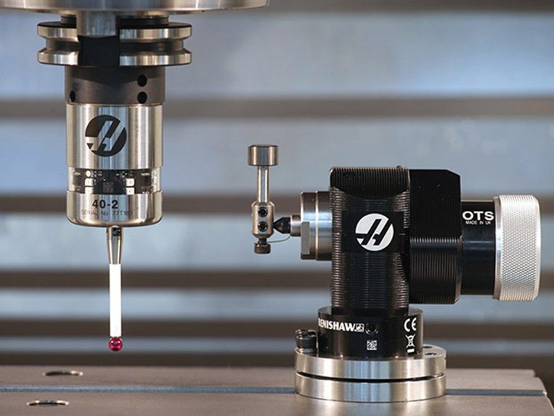
Installer et calibrer le système de palpeur intuitif sans fil (WIPS) (s'il est équipé).

Pour un guide détaillé sur l'installation et l'étalonnage WIPS, veuillez consulter :

WIPS - Installation

3.2 Redémarrer MM/SMM – Installation

Recently Updated

Mini Mill/Super Mini Mill - Installation


Introduction

Cette procédure vous indique comment installer une machine Mini Mill à redémarrage (MM) ou Super Mini Mill (SMM). Pour installer une Mini Mill sans redémarrage, consultez la procédure Mini Mill / Super Mini Mill – Installation en savoir plus. 

Pour déterminer quel type de version Mini Mill vous avez, consultez le document de  référenceMini Mill/Super Mini Mill - Version machine - Identification.

Outils requis :

  • 3/4" prise
  • 5/32", 1/4", 3/8" Sockets Hex Bit
  • cliquet
  • 3/4", 1,5" clé à molette
  • mètre
  • 0,0005" ou 1 micron Test Indicator and Magnetic Base
  • T-2181 SERVICE TOOL, LEVELING TOOL ou Precision Machinist Level, 0,0005" division

Leveling Screws Hardware

Note: The washers [1] and nuts [2] are installed during shipping and should be saved for installation and not be discarded.

Note: The washer orientation [3] is important.  The conical part of the washer should be against the casting,  see illustration.

Remove Rust Inhibitor

To safely and effectively remove rust inhibitor from way covers and other non-painted surfaces:

Initial Scraping

  • Use a plastic scraper to remove the bulk of the rust inhibitor.
  • Avoid using metal tools to prevent scratching or damaging the surface.

 Important: Do not use scotch-brite or metal scrapers, these will scratch the way covers.

Chemical Cleaning

  • Spray the affected areas with a heavy-duty citrus cleaner or Simple Green.
  • Ensure full coverage of all non-painted surfaces coated with rust inhibitor.

Soak Time

  • Allow the cleaner to soak for several minutes to loosen remaining residue.

Wipe Down

  • Use a clean shop towel to thoroughly wipe off the softened rust inhibitor.

Rust Proofing

  • Apply mineral spirits or WD-40 to all exposed metal surfaces to prevent future rust formation.

Important: Always wear gloves and eye protection when handling chemical cleaners. Dispose of used towels and cleaning agents according to local environmental regulations.

 Important: To avoid any contamination of the way cover seals with the sticky residue. Do not move any of the axes until all the rust inhibitor has been removed.

Rust Inhibitor - Safety Data Sheet (SDS)

Air Connection

Connect the air supply at the lube panel.

 Note: For air requirements refer to the decal that is located on the lube cabinet door.

Follow the Air Gun and Hose Installation procedure to install or replace the Air Gun.

 Note: Some installation kits will come with a spare air gun assembly.

Electrical Installation

 DANGER: Working with the electrical services required for CNC machines is extremely hazardous and can result in serious injury or death.

Before connecting line wires to the CNC:

  • Turn off all power to the machine at the source.
  • Perform a Lockout-Tagout (LOTO) procedure to ensure the power remains off during service.
  • Verify that power has been disconnected by using an AC voltage detector on all incoming lines.

If you are uncertain about how to safely disconnect power or perform LOTO procedures:

  • Do not proceed.
  • Contact qualified personnel or obtain appropriate assistance before continuing.

Failure to follow these precautions may result in electrical shock, equipment damage, or fatal injury.

1

Initial Control Inspection

Danger: At this point, there should be no electrical connection to the machine. Electrical panel must be closed and secured. When main switch is on, there is HIGH VOLTAGE throughout the electrical panel (including the circuit boards and logic circuits) and some components operate at high temperatures. Therefore, exercise extreme caution when working in the panel.

  • Set the main breaker switch at the upper right of the electrical panel on the back of the machine to OFF.
  • Using a screwdriver, unlock the two latches on the panel door, unlock the cabinet with the key and open the door.
  • Take sufficient time to check all the components and connectors associated with the circuit boards. Look for any cables that have become disconnected, look for any signs damage and loose parts in the bottom of the panel box. If there are any signs that the machine was mishandled, call the factory before proceeding.

2

1-Phase Machines: Insert each power lead into the wire cover.  Connect the two power leads to L1 and L3 terminals on top of the main circuit breaker.

3-Phase Machines: Insert each power lead into the wire cover.  Connect the three power leads to L1, L2 and L3 terminals on top of the main circuit breaker.

Connect the separate ground line to the ground bus to the left of the terminals.

For 3-phase machines, check to see what type of power configuration is supplying the machine. Take voltage measurements of each power lead to ground line. Then refer to RD0084 - Input Power Configurations to determine which power lead should be connected to the L1 terminal based of the voltage readings and power configuration.

Refer to Haas Main Circuit Breaker - Torque Specifications for what value to torque the circuit breaker power leads.

 Note: Make sure that the leads actually go into the terminal-block clamps . (A poor connection will cause the machine to run intermittently or have other problems, such as servo overloads.) To check, simply pull on the wires after the screws are tightened.

3

After the line voltage is connected to the machine, make sure that main circuit breaker (at top-right of rear cabinet) is OFF . Remove the Lockout / Tagout and Turn ON the power at the source. Using a digital voltmeter and appropriate safety procedures: 

1-Phase Machines: Measure the AC voltage across L1 & L3 at the main circuit breaker.  The AC voltage must be between 220 - 250 volts .
Note: Lower or higher than this voltage can generate low/high voltage alarms.

3-Phase Machines : Measure the AC voltage between all three pair phases at the main circuit breaker. 

The AC voltage must be between 195 and 260 volts (360 and 480 volts for high voltage option).

SMinimill - Reboot: The AC voltage must be between 198 and 242 volts for machines without a high voltage transformer.  Refer to the Minimill/SMinimill - Identification document.

 Note: Wide voltage fluctuations are common in many industrial areas; minimum and maximum voltage supplied to a machine while it is in operation must be known. U.S. National Electrical Code specifies that machines should operate with a variation of +5% to -5% around an average supply voltage. If problems with line voltage occur, or low line voltage is suspected, an external transformer may be used. If you suspect voltage problems, voltage should be checked every hour or two during a typical day to be sure it does not fluctuate more than +5% or -5% from an average.

4

Important: With the main circuit breaker turned OFF.

Check the transformer taps at the bottom-right corner of the rear cabinet.

1-Phase Machines: The input voltage cable must be moved to the connector which corresponds to the average voltage measured in the above step.

3-Phase Machines:  The input voltage cables labeled 74, 75, and 76 must be moved to the terminal block triple which corresponds to the average voltage measured in the above step.

5

Transformer T5 supplies 24VAC used to power the main contactor. There are two versions of this transformer for use on a 240 and 400V machines. The 240V transformer has two input connectors located about two inches from the transformer, which allow it to be connected to either 180-220V or 221-240V.

Users that have 220V-240V RMS input power should use the connector labeled 221-240V, while users with 190-220V input power should use the connector labeled 180-220V. Failure to use the correct input connector will result in either overheating of the main contactor or failure to reliably engage the main contactor.

The 480V (option) T5 transformer has three input connectors, labeled 340-380V, 381-440V and 441-480V.

Users with 340-380V 50/60Hz power should use the 340-380V connector while users with 380V-440V 50/60Hz power should use the 381-440V connector.

Important: Set the main circuit breaker to ON. Check for evidence of problems, such as the smell of overheating components or smoke. If such problems are indicated, immediately set the main circuit breaker to OFF and call the factory before proceeding.

After the power is on, measure the voltage across the bottom terminals on the main circuit breaker. It should be the same as the measurements where the input power connects to the main breaker. If there are any problems, check the wiring.

6

Apply power to the control by pressing the Power-On switch on the front panel.

Check the DC Voltage and AC Line Voltage gauges in Diagnostics. The DC Voltage gauge must read between 310 - 360V. The AC Line Voltage must be between 90 and 105 percent. If the voltage is outside these limits, turn off the power and recheck steps 2 and 3. If the voltage is still outside these limits, call the factory.

7

Electrical power must be phased properly to avoid damage to your equipment. The Power Supply Assembly PC board incorporates a "Phase Detect" circuit with neon indicators. When the orange neon is lit (NE5), the phasing is incorrect. If the green neon is lit (NE6), the phasing is correct. If both neon indicators are lit, you have a loose wire; check the connections. Adjust phasing by setting the source power to off and then swapping L1 and L2 of the incoming power lines at the main circuit breaker.

Danger: ALL POWER TO CNC MUST BE TURNED OFF LOCKOUT-TAGOUT AT THE SOURCE PRIOR TO ADJUSTING PHASING. ALWAYS DOUBLE CHECK THE INCOMING LINES WITH AN AC VOLTAGE DETECTOR.

Turn off the power and set the main circuit breaker to OFF. Close the door, lock the latches, and turn the power back on.

Remove the key from the control cabinet and give it to the shop manager.

8

Activation

When the machine is properly placed and connected to both air and electrical power, it is ready for final installation (removing shipping blocks, leveling, spindle sweep, etc.) and software activation. The HFO service technician does this. Contact the local HFO to schedule the work.

IMPORTANT:  Machines equipped with motion sensors must be rough‑leveled before attempting to arm the motion sensor.  For detailed instructions, refer to Service Notification - SA0007.  Access to this document is restricted to Haas Factory Outlet personnel.

Shipping Bracket Removal

1

Retirez les deux (x2) vis supérieures [1] en tenant le boîtier de commande dans la position verrouillée.

Enlevez le boîtier de commande pour accéder aux deux (x2) vis restantes [2] situées près de l'arrière du boîtier de commande et retirez-les. 

Retirez le boulon à épaulement [3] qui maintient la porte de l’opérateur en place. Accédez à ce boulon par l’ouverture de la porte de l’opérateur. 

À l’intérieur de la machine, retirez les boulons qui fixent le support d’expédition de la broche [4] de la table au boîtier de broche.

 Remarque :  À ce stade, le support de broche n’est pas démontable. Retirez le support après avoir mis sous tension la machine et déplacé la broche vers le haut

Machine Leveling

IMPORTANT:  Machines equipped with motion sensors must be rough‑leveled before attempting to arm the motion sensor.  For detailed instructions, refer to Service Notification - SA0007.  Access to this document is restricted to Haas Factory Outlet personnel.

1

Clean and jog the table so the spindle is on the center of travel.

Place the level on top the table aligning the long vial to be parallel with the X-axis. Use the T-slots as reference.

The long vial on the level represents the X axis and the short vial on the level represents the Y axis. 

Loosen the (4x) leveling screws on the corners of the base. Make small adjustments  to leveling screws 1 and 3 to adjust the X axis level. After each adjustment, note the position of the  bubble in the short vial. 

If the position of the bubble in the short vial isn't centered, make adjustments to leveling screws 1 and 2 as required. 

Repeat this process until both bubbles are in their center positions. 

2

Adjust (x4) leveling screws to be snug against the ground. 

Jog the table towards the spindle column while observing the position of the bubble in the long vial. If the bubble is not centered, make a small adjustment to the lower corner 1 & 3 if titled towards the column end or on the higher corner 2 & 4 if tilted towards the operator end.

Repeat this process with the table on the other end of the machine. 

Spindle Sweep Check

1

Attach indicator to spindle head. Position the table and indicator to sweep a circle 10" in diameter.
 
Place a gauge block on the table.
 
Jog the spindle down and zero the indicator at Position 1. 
 
Using a gauge block every 90 degrees, check that the difference in these measurements don't exceed 0.0005". If it does, check the machine level.

Lubrication Verification

1

Run the spindle run-in program.

 Note: For 10K spindles and above use a balanced tool holder

Examine the sight glass, make sure the correct number of drops are fall through the sight glass.

Examine the fittings [1,2] on top of the oil pump tank.

The oil collects on top of the oil pump tank [3] either behind or in front of the sight glass bracket, underneath the leaking fitting.

Tighten any leaking fittings.

2

Go to the Maintenance tab.

Press [F2] to cycle an axis lubrication test.

Inspect the gauge on the lubrication system.  Make sure it holds pressure.

Convenience Package Install

1

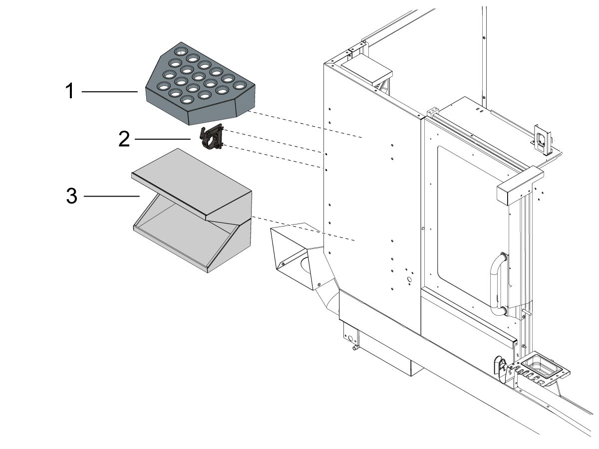
Fixez le plateau à outils [1] à l’avant de la cartérisation de la machine.

Fixez le porte-outil [2] sous le plateau à outils [1] à l’avant de la cartérisation de la machine.

Fixez la table d’écriture [3] sous le porte-outil [2] à l’avant de la cartérisation de la machine.

Coolant Hose Installation

1

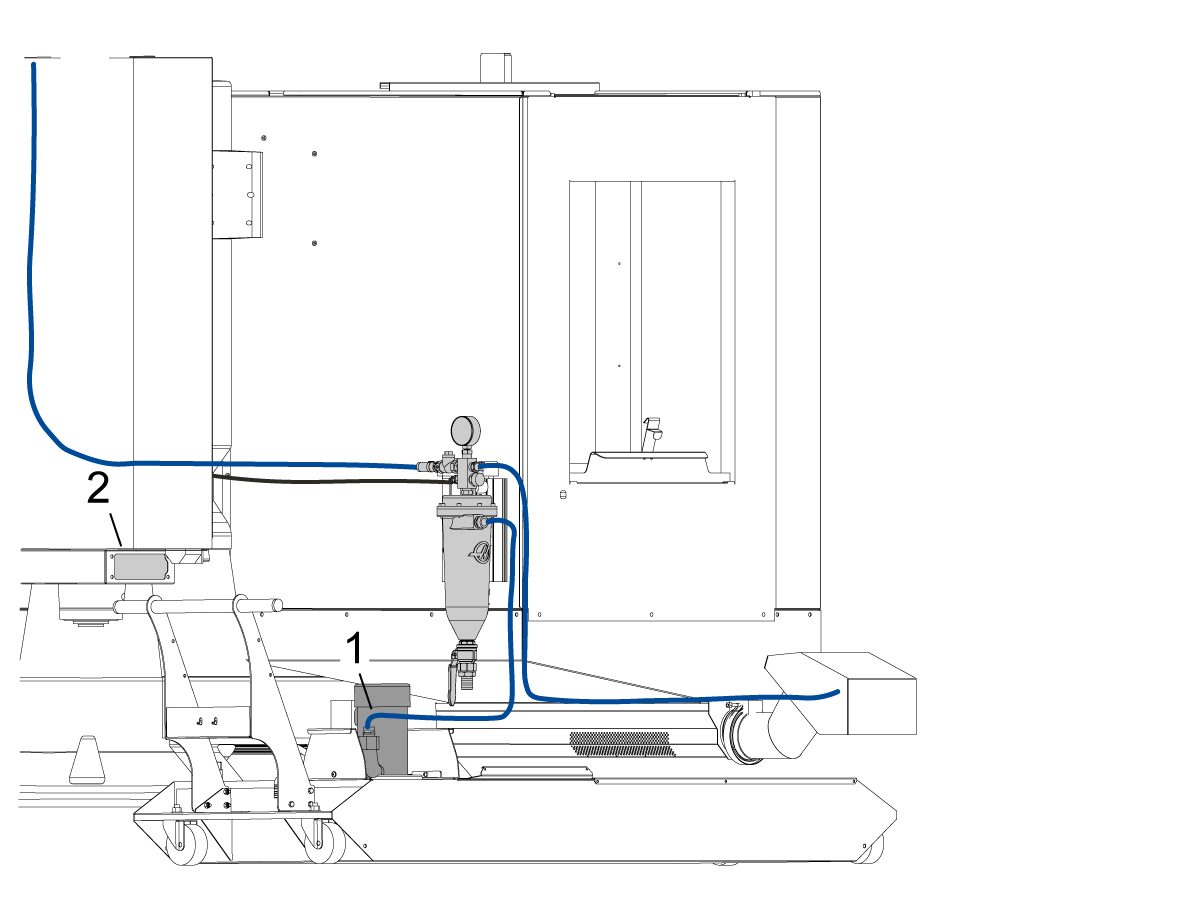
Fixez le tuyau de liquide de coupe bleu depuis l’entrée de filtre à la prise de pompe de liquide de coupe [1].

Branchez la pompe de liquide de coupe à la prise de liquide de coupe à faible pression [2].

Installez le capteur de niveau du liquide de coupe. Consultez le document Capteur de flotteur de liquide de coupe - NGC - Installation pour plus d'informations. 

Capteur flotteur de niveau du liquide de coupe - NGC - Installation

Machine Operation

1

Opération de spindle d'essai

Exécutez le programme de rodage de broche O09221.

Dans le cas d'un bruit de broche inhabituel, exécutez un test de vibration. Pour un guide sur la façon d'effectuer un test de vibration de broche, consultez : 

Analyse des vibrations - Interface Ethernet
Analyse des vibrations - Interface RS-232

2

Testez le fonctionnement du liquide de refroidissement

Remplissez le réservoir de liquide de coupe avec la quantité de liquide de coupe nécessaire pour remplir le réservoir.

Appliquez le liquide de coupe en appuyant sur [COOLANT] sur la console de commande.

3

Testez les verrouillages de porte

Appuyez sur [MDI]. Saisissez S500 M3; et appuyez sur [ENTER].

Assurez-vous que la machine n'EST PAS en SETUP MODE en vérifiant l’INTERRUPTEUR À CLÉ sur le côté du boîtier de commande

Avec la porte ouverte, appuyez sur [CYCLE START]. La machine doit vous demander de fermer la porte et d'appuyer sur [CYCLE START].

La porte fermée, appuyez sur [CYCLE START]. L'épingle de verrouillage doit s'étendre et la broche commence à tourner.

 IMPORTANT : Avec la broche en rotation, testez les serrures de la porte en essayant d'ouvrir la porte. La broche ne doit pas cesser de tourner. 

4

Caractéristiques de sécurité d'essai

Insérez la clé de verrouillage de configuration/exécution (N°2007) à la fente de clé inférieure et tournez-là [2] en position déverrouillée.

Vérifiez que la clé ne peut être retirée que de la position verrouillée.

Insérez la clé de verrouillage de la mémoire (N°2341) dans la fente de clé supérieure et tournez-là [1] en position verrouillée.

Vérifiez que la clé peut être retirée de l'une ou l'autre position.

Avec la clé de verrouillage de mémoire dans la position verrouillée, vérifiez que les modifications ne peuvent pas être apportées aux paramètres ou aux programmes.

Vérifiez que les deux fenêtres se verrouillent en position descendante.

5

Convoyeur de copeaux à vis sans fin

Testez le Chip Auger (s'il est équipé).

Appuyez sur [CHIP FWD] et [CHIP REV] sur la commande.

6

WIPS Calibration NGC (en) 

Si votre machine inclut l’option WIPS, veuillez consulter le lien suivant pour obtenir des instructions sur la procédure de calibrage :

WIPS Calibration NGC (en)

Mill Maintenance Schedule

Assurez-vous que vos machines Haas fonctionnent à un pic de performance de pointe tout en évitant des temps d’arrêt imprévus. Un programme d’entretien vous permet de gérer votre planning plutôt que de vous faire surprendre par des événements inopportuns. Veuillez consulter le lien ci-dessous pour les intervalles d'entretien recommandés.

Calendrier d’entretien de la fraiseuse

3.3 Ancrage

Recently Updated

Instructions d'ancrage


Introduction

This procedure will show you how to install the Drop-In expansion style anchors to a Haas CNC.

NOTE: If the machine was built before Jan 2020 or is a VS or HDC series machine, please refer to the epoxy style anchoring procedure (AD0212) click here.

For instructions on how to anchor the various components for the Haas Cobot kits refer to the Haas Cobot - Anchoring instruction page.

This procedure applies to the following Service Kits:

Mill
Model Part Number
DC-1 93-1001018
DC-2 93-1001019
DC-4 93-1001211
DT/DM-1, DT/DM-2 93-1000601
DT/DM-3 93-1001136
EC-400/VC-400

93-1000567

See Note Below

EC-500/50 93-1001145
EC-1600/UMC-1600H 93-1000535
EC-630 93-1000856
GM-1 93-1001115
GM-1XT 93-1001235
GM-2-3AX 93-1000574
GM-2-5AX 93-1000542
GR-510 93-1000574
GR-712 93-1000574
MM/SMM Reboot 93-1001016
UMC-350HD 93-1000780
UMC-400/SS 93-1001224
UMC-500/SS 93-1000379
UMC-750/SS (NON REBOOT) 93-1000380
UMC-750/SS (REBOOT)  93-1001324
UMC-1000/SS (REBOOT) 93-1001324
UMC-1250/SS 93-1000644
UMC-1500-DUO/SS-DUO 93-1000871
VF-1/2, VF-2TR, VF-2SS 93-1000534
VF-2YT, VF-2SSYT, VM-2 93-1000549
 VF-3/3SS, VF-4/4SS 93-1000550
VF-3YT/3YTSS, VF-3YT/50, VF-5/40, VF-5/40TR, VF-5/40XT, VF-5SS, VF-5/50, VF-5/50TR, VF-5/50XT, VM-3, VMT-750 93-1000548
VF-6/40, VF-6SS, VF-6/40TR, VF-7/40, VF-6/50, VF-6/50TR, VF-7/50, VM-6 (Base with 8 leveling feet) Built between January 2020 and September 6th 2023 93-1000547
VF-8/40, VF-9/40, VF-8/50, VF-9/50, VR-8, VR-9 (Base with 8 leveling feet) Built between January 2020 and October 6th 2023 93-1000546
VF-10/40, VF-12/40, VF-10/50, VF-12/50 (Base with 8 leveling feet) 93-1000545
VF-11/40, VF-11/50, VR-11 (Base with 8 leveling feet) 93-1000544
VF-6/6TR/6SS/7/10/12 both 40T & 50T and VM-6 (Base with 6 leveling feet) Built September 7th 2023 and later 93-1000999
VF-8/9/11/14 both 40T & 50T and VR-8/9/11/14 (Base with 6 leveling feet) Built October 7th 2023 and later 93-1001000
VS-3 93-1000870
Updated
Note: For EC-400 anchor kit 93-1000567 only. EC-400 Anchor Template 96-0286 only permits 7 of the 8 anchor locations to be utilized. The anchor spot under the front door is inaccessible due to improper enclosure spacing. This is corrected with EC-400 Anchor Template 96-0286A, which shifts the front anchor location to a more accessible spot. 
 
Pallet Pool/RPL
Model Part Number
UMC-500PP 93-3526
UMC-750PP (V1) See Note Below
UMC-750PP (V2) 93-3527
UMC-1000PP (V2) 93-3527
UMC-1250PP See Note Below
EC-400PP 93-3525
VF-2YTPP See Note Below
VF-4 PP See Note Below
Robot Pallet Loader See Note Below
Note: There is currently no 93-xxxx service kit for the following models:
  • (30-12644B + 96-0316A) UMC-750 Pallet Pool (V1)
  • (30-12644B + 96-0364) VF-2YT Pallet Pool
  • (30-12644B + 96-0383) VF-4 Pallet Pool
  • (30-12644B + 96-0388) Robot Pallet Loader

You would need to order individual parts,  please contact your Local Haas Factory Outlet for availability.

Lathe
Model Part Number
ST-10/10Y/15/15Y 93-1000378
ST-10L/10LY/15L/15LY 93-1000855
ST-20/25/20Y/25Y 93-1000552
ST-20L/20LY/25L/25LY/28L/28LY 93-1001005
ST-30/35/30Y/35Y, DS-30Y (REBOOT ONLY) 93-1000541
ST-30L/35L/LY 93-1001079
ST-40 93-1000540
ST-40/40Y (Reboot) 93-1000819
ST-40L 93-1000539
ST-40L (Reboot) 93-1000820
ST-40S/45S/SY  93-1001012
ST-50/55 93-1000538
TL-1 93-1000537
TL-2 93-1000536
Extended Liner System
ST-10/10L/10Y/10LY 93-1000844
93-1000845

Tools required:

  • Paint markers
  • Painters Tape
  • Pipe cleaner brush
  • 5 lb. Sledge Hammer
  • SDS Plus Hammer Drill
    Note:  The SDS-Plus Hammer drill should be rated for 1" bit.

Video Instructions

Anchor Template Placement

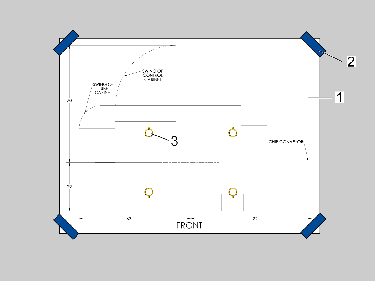
  1. Unroll machine anchoring template [1].
  2. Use centerlines and provided reference sheet dimensions, measure distances to nearest allowable obstructions.
  3. Once position is established, taped the corners [2] of the anchoring template to the foundation.  Keep the template as flat as possible.
  4. Spray paint the foundation in the cutout areas of the template [3].
  5. Let the paint dry for 5-10 minutes.
  6. Remove the anchoring template [1].

Drill Holes and Set the Anchors

Use the provided SDS-Plus Style drill for the following steps:

  • Drill specified number of 5/8" holes at depth 2.00 - 2.25" each.  
    • Drill bit should be perpendicular to foundation.
  • Clean the holes with pipe cleaner.
  • Use compressed air and a vacuum to clear holes.
  • Repeat for the number of leveling pads.
  • Cover the holes with tape to protect from unwanted debris while the other holes are drilled.
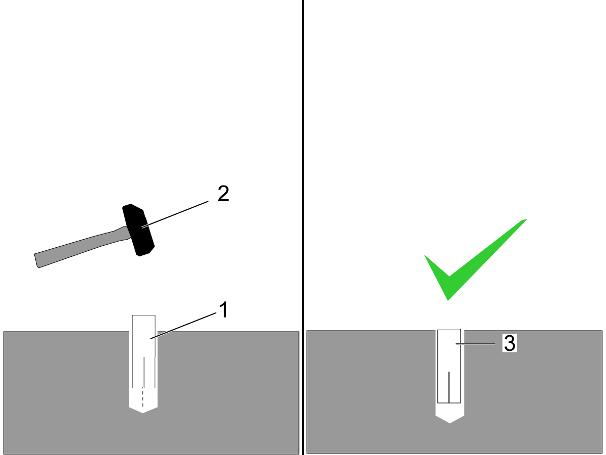
  • Using the hammer [2] set the drop-in anchor [1] flush with the concrete [3].

    Note:  Do not use the set tool to drive the anchor.  
  • Use the provided setting tool [1] and hammer [2], to seat the anchor in the concrete.
  • Make sure that the anchors are seated flush [3], use the setting tool as a gauge.
    Note:  Be careful not to overdrive the anchor [4] to far inside the hole.

Machine Placement

  1. Once the anchors are set, place the leveling pads on the spray painted cross-hairs.
  2. Place the machine on the leveling pads.
  3. Set the machine height.
  4. Level the machine
  5. Tighten down the machine locknuts.

Anchoring Strap Installation

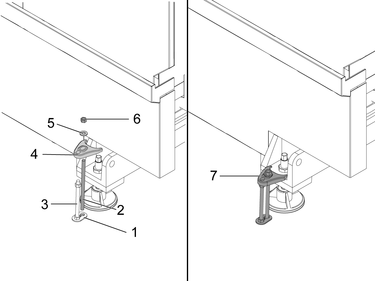
  1. Place the thrust plate flush [1] with the foundation.
  2. Thread stud [2] into the anchor location using two lock nuts.
  3. Place 1/2-13 hex nut on the 1/2-13 hex bolt [3] on top of the thrust plate.
  4. Place the anchoring strap [4].
  5. Place the washer [5] on the threaded rod.
  6. Thread the 1/2-13 hex nut [6] into the threaded rod.
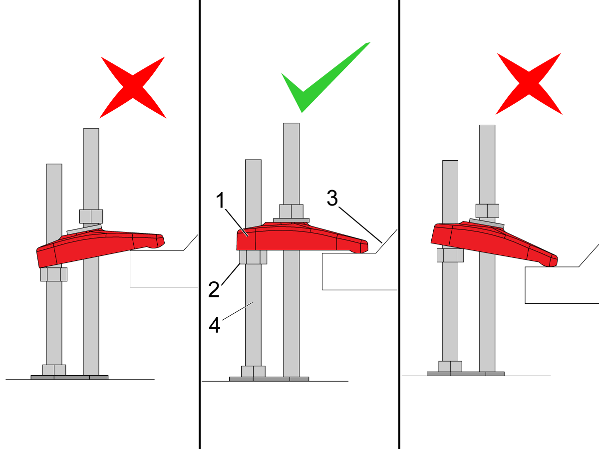
  7. Be sure the anchoring strap [7] remains parallel to the clamped casting surface.
  8. Torque 1/2-13 hex nut to 25ft-lbs (34 nm).

Make sure that the anchor strap [1] is level on the hex nut [2] and the machine base [3].

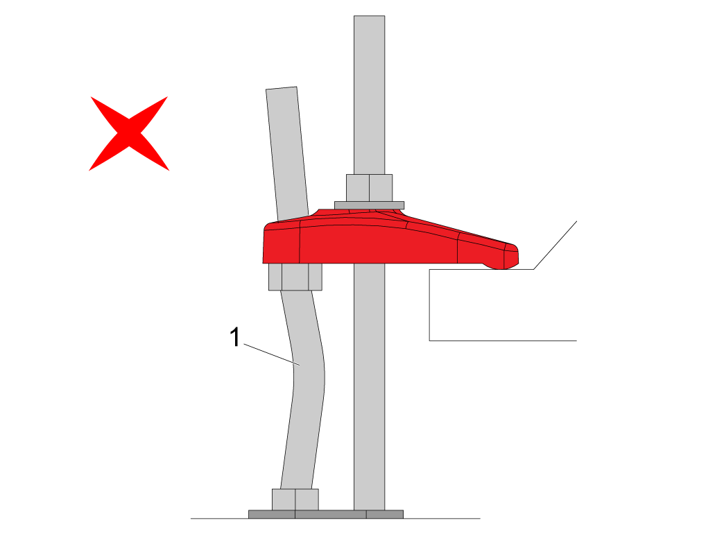
NOTE: Make sure the threaded stud [4] is perpendicular to the floor and not bent. 

Make sure the threaded stud welded to the base is not bent as shown in the image [1].

If this occurs make sure that the anchor holes are drilled straight and re-drill them if necessary. 

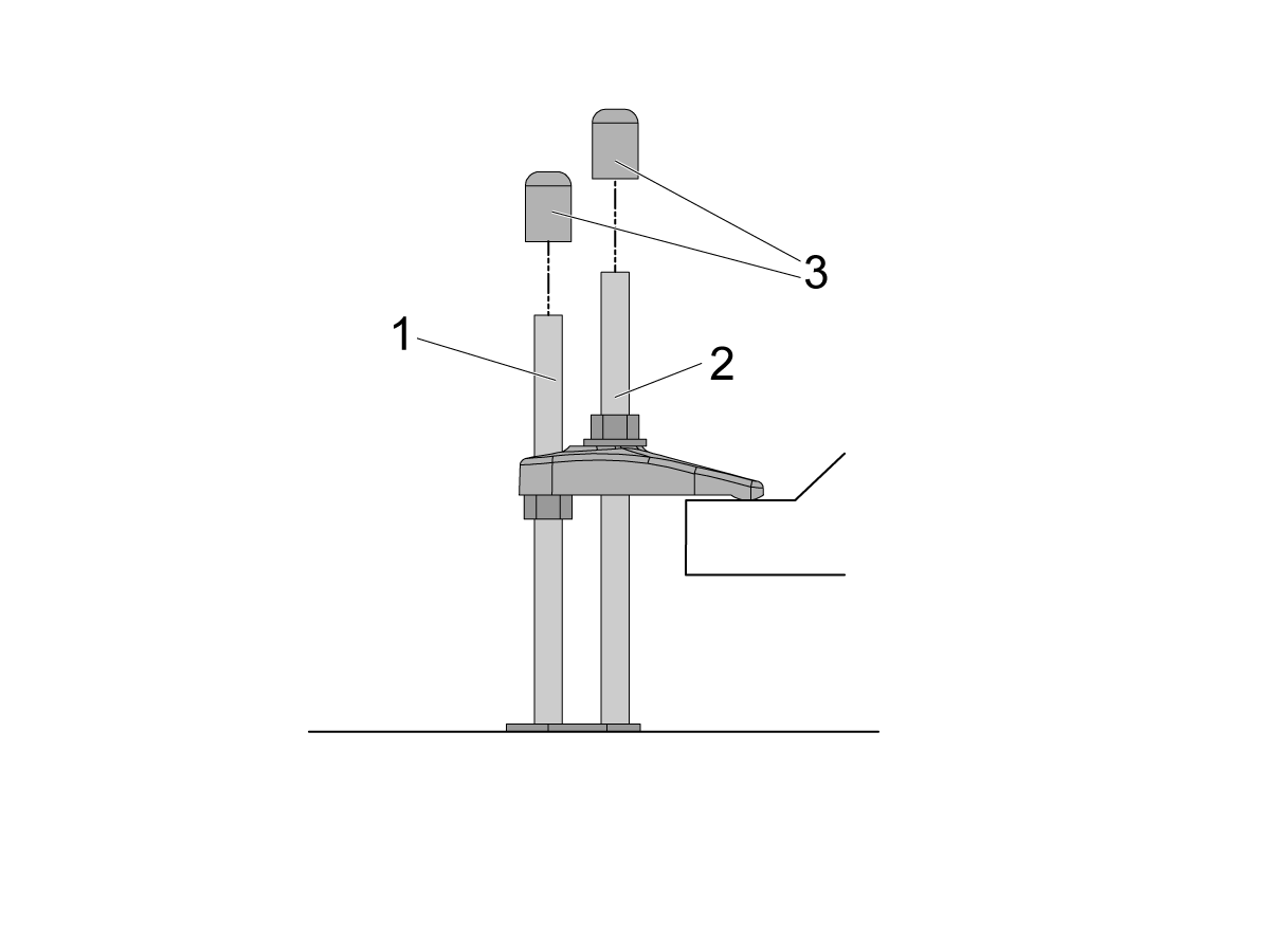
If there is clearance on the anchor [1] and stud [2] place the end caps [3] on the ends as shown in the image. Place these caps on all all anchors.

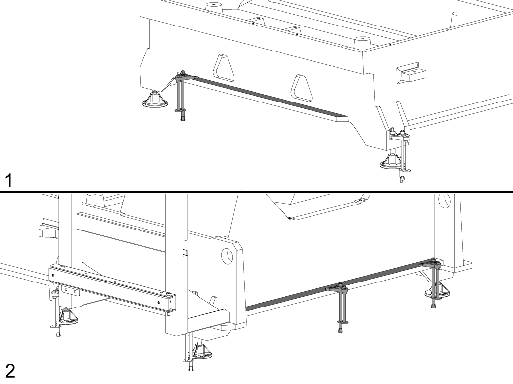
NOTE: The UMC-1250/SS does not have the anchoring fingers on the base foot. The indicated holes on the anchoring layout will have them anchoring down the base flange as shown in the image. Image [1] is the front of the machine, while image [2] is the back of the machine. 

Sheet Metal Anchor Bracket Installation

These instructions are used for installing sheet metal anchor brackets or fence posts for APLs or Haas Robot Packages.

Note: There is no anchor template included with these assemblies. The brackets and fence post anchor holes are used to create the anchor hole locations. The locations are dimensioned in the layouts of the install instructions.

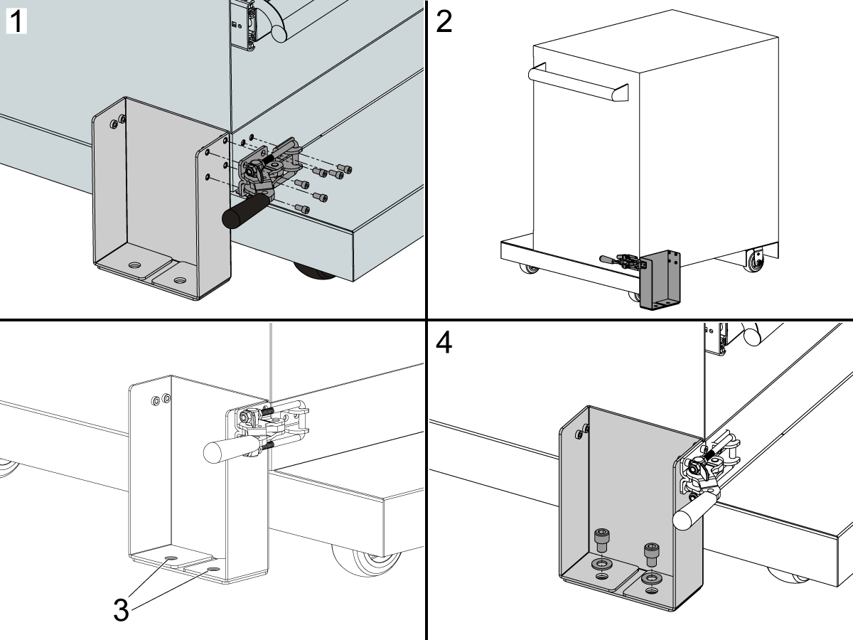
1. Install the Latch Toggle Clamp to the front of the Robot Drawer Cart and Sheet Metal Anchor Bracket.

2. Install the Latch Toggle Clamp to the rear of the Robot Drawer Cart and Sheet Metal Anchor Bracket.

3. The Sheet Metal Anchor Bracket or Fence Post holes are used to mark the drop in anchor hole locations.

4. Install the anchor hardware after the anchors are installed using the Drill Holes and Set the Anchors instructions above.

Recently Viewed Items

You Have No Recently Viewed Items Yet

Commentaires
Haas Logo

Tarification de livraison Haas

Ce prix comprend les frais d’expédition, les droits d’exportation et d’importation, l’assurance et tous les autres frais encourus pendant l’expédition vers un lieu en France convenu avec vous en tant qu’acheteur. Aucun autre frais obligatoire ne peut être ajouté à la livraison d’un Produit CNC Haas.

PRENEZ CONNAISSANCE DES TOUTES DERNIÈRES SUGGESTIONS ET TECHNOLOGIES DE HAAS.

Inscrivez-vous maintenant !   

HAAS TOOLING ACCEPTE CE QUI SUIT :

  • Service et assistance
  • Propriétaires
  • Demande de service
  • Manuels d’utilisation
  • Pièces Haas
  • Demande de réparation de tables rotatives
  • Guides de pré-installation
  • Outils d’achat
  • Fabrication et prix d’une nouvelle machine Haas
  • Stock disponible
  • La liste des tarifs Haas
  • Financement CNCA
  • À propos de Haas
  • Engagement d’accessibilité
  • Principe DNSH
  • Respect des exportations
  • Carrières
  • Certifications et sécurité
  • Contactez-nous
  • Histoire
  • Conditions générales
  • Conditions générales outillage Haas
  • Confidentialité
  • Garantie
  • Communauté Haas
  • Programme de certification Haas
  • Haas Motorsports
  • Gene Haas Foundation
  • Communauté éducative technique Haas
  • Événements
  • Participer aux échanges
  • Facebook
  • X
  • Flickr
  • YouTube
  • LinkedIn
  • Instagram
  • TikTok
© 2026 Haas Automation, Inc. - Machines-outils CNC

This site is protected by reCAPTCHA and the Google Privacy Policy et Terms of Service apply.

2800 Sturgis Rd., Oxnard, CA 93030 / Toll Free: 800-331-6746
Phone: 805-278-1800 / Fax: 805-278-2255