MyHaas 欢迎
!
Haas Tooling 客户订单历史 MyHaas/HaasConnect 登录 注册 Haas Tooling 我的账户 Order History Return History MyHaas/HaasConnect 退出登录 欢迎 我的机床 最近活动 我的报价 我的账户 我的用户 退出登录
寻找您的经销商
  1. 选择语言
    1. English
    2. Deutsch
    3. Español - España
    4. Español - Méjico
    5. Français
    6. Italiano
    7. Český
    8. Nederlands
    9. Magyar
    10. Polski
    11. Svenska
    12. 中文
    13. Suomi
    14. Norsk
    15. الإنجليزية
    16. български
    17. Hrvatski
    18. Ελληνικά
    19. Slovenský
    20. Slovenščina
    21. 한국어
    22. 日本語
Search
  • 设备 Main Menu
    • Haas 立式加工中心 立式加工中心
      立式加工中心
      立式加工中心 View All
      • 立式加工中心
      • VF 系列
      • 通用机床
      • VR 系列
      • 托盘更换 VMC
      • 迷你铣床
      • 模具机床
      • 钻孔/攻丝/铣削系列
      • 工具铣床
      • 紧凑型铣床
      • 龙门系列
      • 超大型 VMC
      • 桌面铣床
      • 铣床 APL 自动装料器
      • 紧凑型自动装料器
    • Product Image 多轴解决方案
      多轴解决方案
      多轴解决方案 View All
      • 多轴解决方案
      • Y 轴车削中心
      • 5 轴铣床
    • Haas 车削中心 车削中心
      车削中心
      车削中心 View All
      • 车削中心
      • ST 系列
      • 双主轴
      • 工具车削中心
      • 紧凑型车床
      • Haas 送料器 V2
      • 车床 APL 自动装料器
    • Haas 卧式加工中心 卧式加工中心
      卧式加工中心
      卧式加工中心 View All
      • 卧式加工中心
      • 50 锥度
      • 40 锥度
    • Haas 转台和分度器 转台和分度器
      转台和分度器
      转台和分度器 View All
      • 转台和分度器
      • 回转工作台
      • 分度器
      • 5 轴转台
      • 超大型回转设备
    • Product Image 自动化系统
      自动化系统
      自动化系统 View All
      • 自动化系统
      • 机器人套装
      • 自动上料机
      • 多托盘系统
      • Haas 进给器
      • Models
    • 快速链接 特种系列  特种系列 
      HAAS 招贤纳士 HAAS 招贤纳士 配置和价格 配置和价格 价目表 价目表 最新动态 最新动态 您的首台数控设备 您的首台数控设备 HAAS SIX PACK HAAS SIX PACK
      采购指南
      • Haas 机床配置和价格
      • 价目表
      • 可用存货
      • CNCA 金融计划
      想和专人讨论?

      Haas 专卖店 (HFO) 能够解答您的问题,并引导您选择最合适的选项。

      CONTACT YOUR DISTRIBUTOR >
  • 选项 Main Menu
    • Product Image 主轴
      主轴
      主轴 View All
      • 主轴
    • Product Image 刀库
      刀库
      刀库 View All
      • 刀库
    • Product Image 第 4 轴 |第 5 轴
      第 4 轴 |第 5 轴
      第 4 轴 |第 5 轴 View All
      • 第 4 轴 |第 5 轴
    • Product Image 刀塔和动力刀
      刀塔和动力刀
      刀塔和动力刀 View All
      • 刀塔和动力刀
    • Product Image 探测
      探测
      探测 View All
      • 探测
    • Haas 切屑和冷却液管理 切屑和冷却液管理
      切屑和冷却液管理
      切屑和冷却液管理 View All
      • 切屑和冷却液管理
    • Haas 控制系统 Haas 控制系统
      Haas 控制系统
      Haas 控制系统 View All
      • Haas 控制系统
    • Product Image 产品选项
      产品选项
      产品选项 View All
      • 产品选项
    • Product Image 刀具和夹具
      刀具和夹具
      刀具和夹具 View All
      • 刀具和夹具
    • Product Image 工件夹具
      工件夹具
      工件夹具 View All
      • 工件夹具
    • Product Image 5 轴解决方案
      5 轴解决方案
      5 轴解决方案 View All
      • 5 轴解决方案
      • 5 Easy Steps to 5-Axis
    • Product Image 自动化
      自动化
      自动化 View All
      • 自动化
    • 快速链接 特种系列  特种系列 
      HAAS 招贤纳士 HAAS 招贤纳士 配置和价格 配置和价格 价目表 价目表 最新动态 最新动态 您的首台数控设备 您的首台数控设备 HAAS SIX PACK HAAS SIX PACK
      采购指南
      • Haas 机床配置和价格
      • 价目表
      • 可用存货
      • CNCA 金融计划
      想和专人讨论?

      Haas 专卖店 (HFO) 能够解答您的问题,并引导您选择最合适的选项。

      CONTACT YOUR DISTRIBUTOR >
  • Why Haas Main Menu
      探索 Haas 的不同之处
    • 为何选择 Haas
    • MyHaas
    • 教育社区
    • 工业 4.0
    • Haas 认证
    • 客户感言
  • 服务 Main Menu
      欢迎来到 Haas Service
      服务主页 操作手册 方法程序 故障排除指南 预防性维护 Haas 零件 Haas Tooling 视频库
  • 视频 Main Menu
  • 联系我们

×

搜索结果

Web Pages

Images

    • <
    • 1
    • >
MyHaas 欢迎
!
Haas Tooling 客户订单历史 MyHaas/HaasConnect 登录 注册 Haas Tooling 我的账户 Order History Return History MyHaas/HaasConnect 退出登录 欢迎 我的机床 最近活动 我的报价 我的账户 我的用户 退出登录
寻找您的经销商
  1. 选择语言
    1. English
    2. Deutsch
    3. Español - España
    4. Español - Méjico
    5. Français
    6. Italiano
    7. Český
    8. Nederlands
    9. Magyar
    10. Polski
    11. Svenska
    12. 中文
    13. Suomi
    14. Norsk
    15. الإنجليزية
    16. български
    17. Hrvatski
    18. Ελληνικά
    19. Slovenský
    20. Slovenščina
    21. 한국어
    22. 日本語
Search
×

搜索结果

Web Pages

Images

    • <
    • 1
    • >

VS-Series- Installation - NGC

服务首页 方法程序 VS-Series - Installation - NGC
Recently Updated Last updated: 10/27/2022

VS-Series - Installation - NGC

Revision 1


Under Construction

VS-Series - Installation - NGC

- 跳至部分 - 1. Introduction (1 步骤) 2. Leveling Screws Hardware 3. Leveling Overview 4. Tool Changer Installation (2 步骤) 5. Machine Placement (3 步骤) 6. INSTALL COUNTER BALANCE CYLINDER (4 步骤) 7. Wiring the Machine (3 步骤) 8. Removal of Rust Inhibitor 9. Electrical Connections 10. Unblocking the Machine (2 步骤) 11. Machine Leveling (5 步骤) 12. Geometry Check (3 步骤) 13. Final Connection of the Column Base to the Table Base 14. Anchoring the Machine in Place (2 步骤) 15. Completing the Installation (1 步骤) Back to Top

Introduction

1

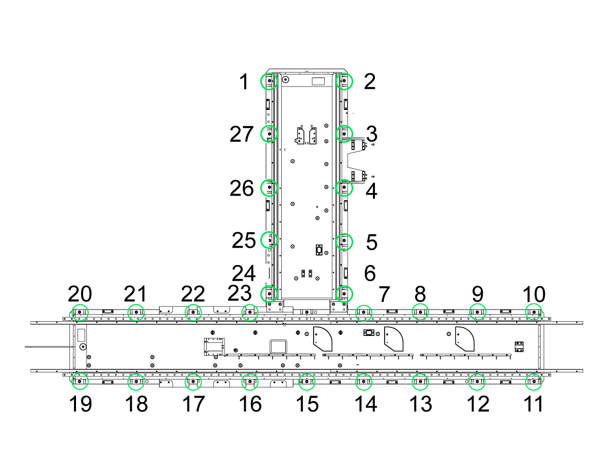
Use these numbers to identify which foot to adjust.

  • Prerequisites:

Adjust each leveling screw until the base is 4" (10 cm) above the floor (3" (76 mm) leveling pad height plus 1" (25 mm) of screw below the bottom of the pad).

 Note: The condition of the foundation may require different heights at some leveling screws to make the machine level.

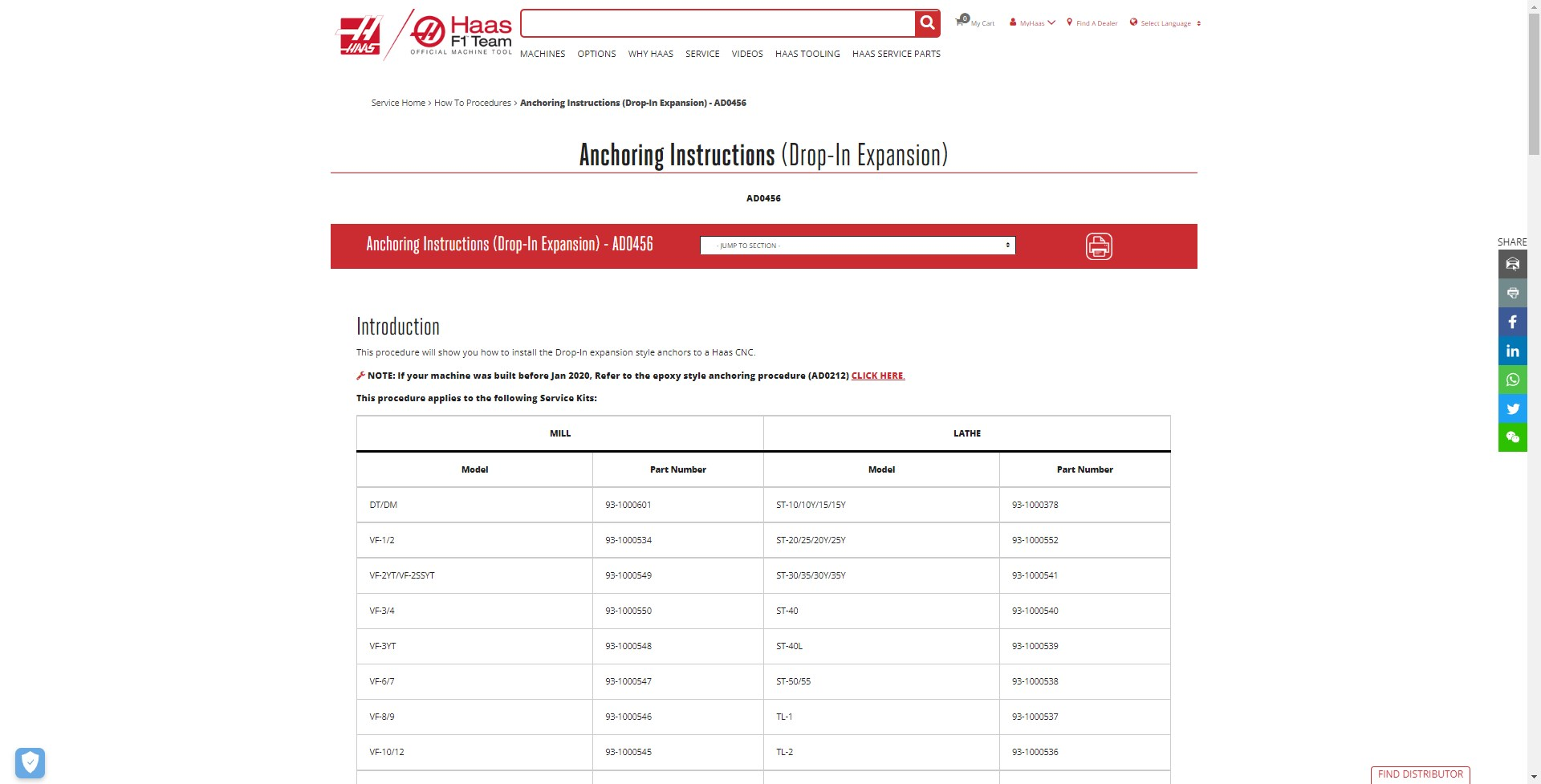
  Important: it is required that the machine be anchored. Refer to the following link: ANCHORING INSTRUCTIONS.

  • Using the anchor pattern from Machine Layout to mark the machine location.
  • Print the anchor footprint from AD0456 to mark anchor location.
    • Important: Footprint must be printed at 1:1 ratio


Tools Required:

  • Electronic differential level, precision bubble level, calibrated to show 0.0005 inch per 10"
  • Test indicator (0.0005")
  • Two ¾" hex wrenches (one open end or box and one ratchet)
  •  600 #  TORQUE  WRENCH , ¾ DRIVE w/ 1.5" Socket
  • 50T X 8” PREC SPINDLE ALIGNMEN TOOL
  •  3 x 4 x 40  GRANITE PARALLEL
  •  3 x 12 x 18  GRANITE TRI SQUARE
  •  2 x 6 x 6  GRANITE PARALLEL 
  • 50T Alignment Split Tool

Leveling Screws Hardware

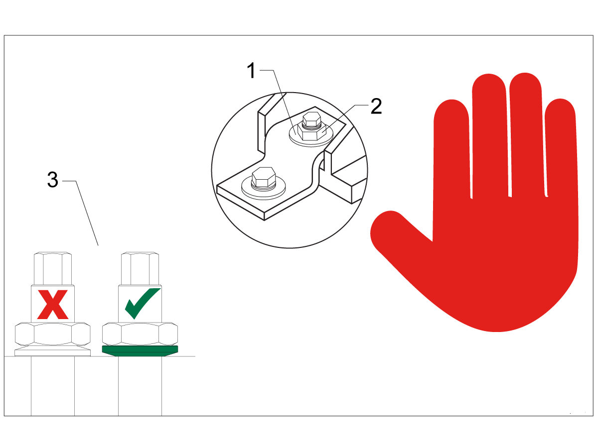
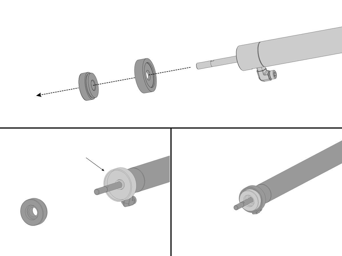
Note: The washers [1] and nuts [2] are installed during shipping and should be saved for installation and not be discarded.

Note: The washer orientation [3] is important.  The conical part of the washer should be against the casting,  see illustration.

Leveling Overview

Wiring connections to power the machine must be made before the Levelling Procedure can be followed. It is required that the machine be anchored in place for best and most consistent results while in use. The anchoring bolts (in accordance with the anchoring instructions) should be installed prior to the machine being set in place.

The installation process will be further aided if, when each base assembly is set in place, a very rough leveling procedure be done. The theoretical distance from the floor to the bottom of the two bases is 4 inches. The use of a machinist scale or small gauge blocks will expedite the process. While all leveling screws and leveling pads are in place measure from the floor to the bottom of each base until the distance is very close to the 4 inch height. This will accomplish two things: First, that the machine is set to the proper height to receive the coolant tank/Conveyor and, second, that the machine will be very much closer to level than without having done this procedure.

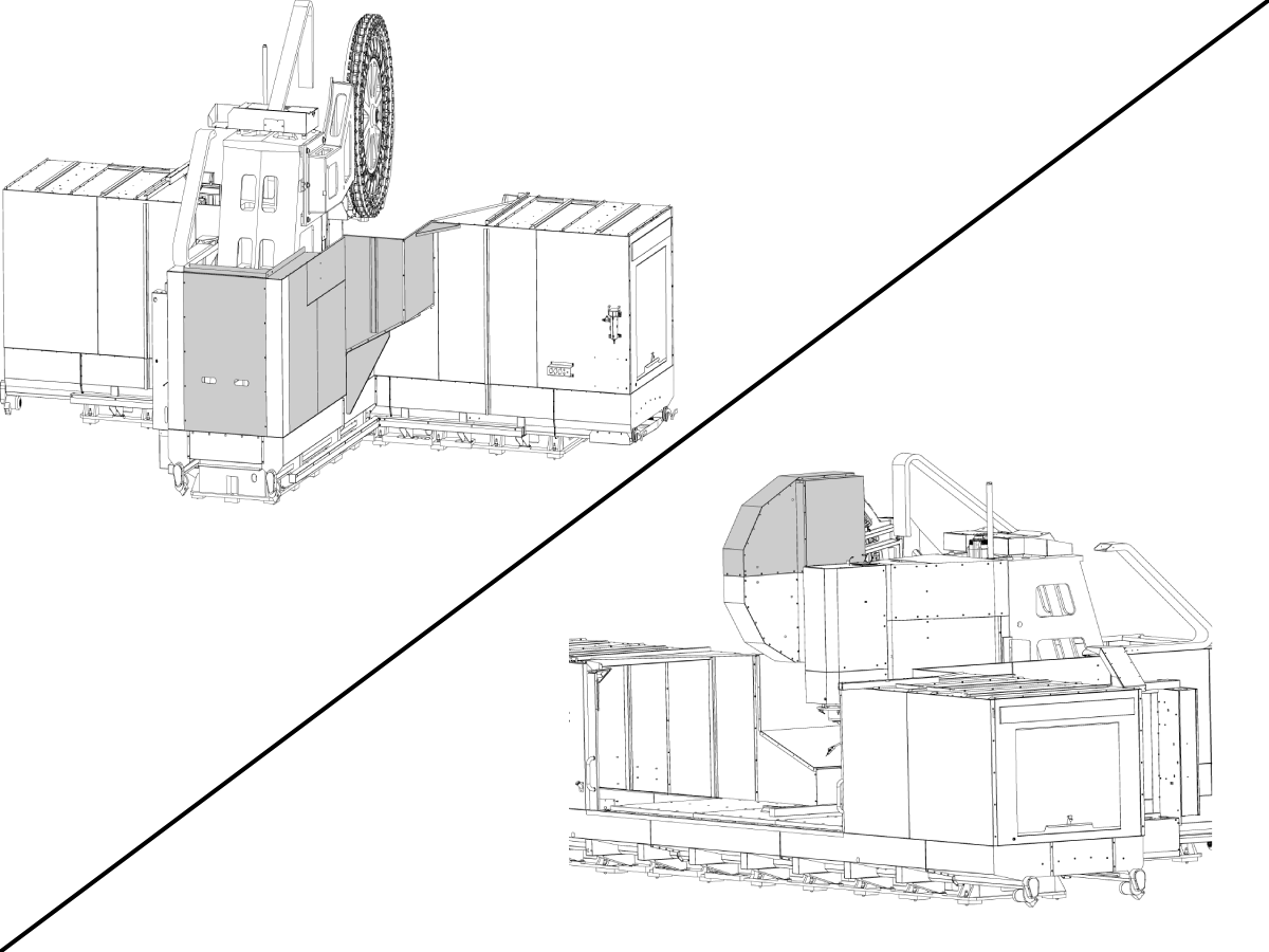
The installation procedure will necessarily follow the general outline below (a more detailed explanation follows). Depending on the available space and equipment it may be simpler to place the column base assembly before the table base assembly.  Regardless of which assembly is placed first, the concepts of the general outline need to be adhered to:

  • Remove the column base assembly from the truck
  • Stone and clean the table base mating flange
  • Remove the table base assembly from the truck and set 6" away from the column
  • Stone and clean the column base mating flange
  • Move the table base to mate with the column base
  • Be certain that all connecting bolts are in place but not tightened
  • Run the Pendant electrical wires over the top of the table enclosure and connect them in Operator pendent
  • Rough level the column base assembly
  • Remove the side panel from under the tool changer assembly
  • Install the counterbalance cylinder and charge the system
  • Relocate the tool changer ** (See Note Below)
  • Remove shipping blocks from the table base assembly 
  • Connect all air/electrical/oil lines between the two assemblies
  • Remove shipping blocks from the column base assembly
  • Power up the control
  • Fine level the column base assembly assembly
  • Fine level table base assembly/squaring the table base assembly to the column.
  • Fully tighten the connecting bolts and tighten anchors
  • Fully check machine geometry
  • Replace the side panel from under the tool changer assembly
  • Install the coolant supply system 
  • Check all motors for rotation/phasing

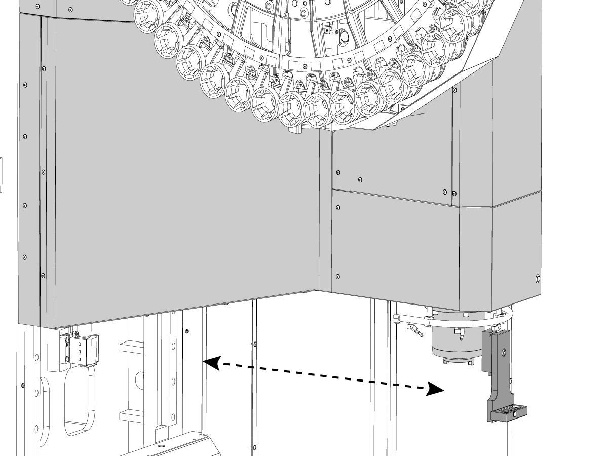
Note: (**)  Depending on the available space and equipment it may be simpler to relocate the tool changer assembly before moving the Column Base into the facility

Tool Changer Installation

1

Important: Depending on the available space and equipment it may be simpler to relocate the tool changer assembly before moving the Column Base into the facility

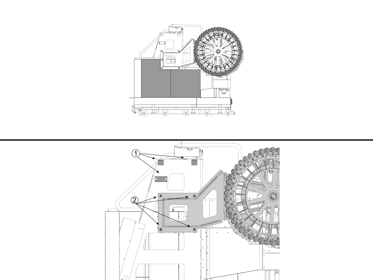
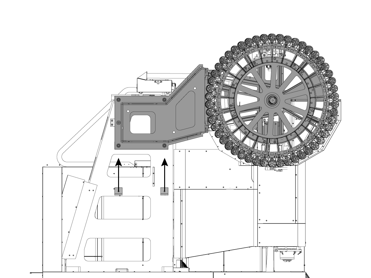
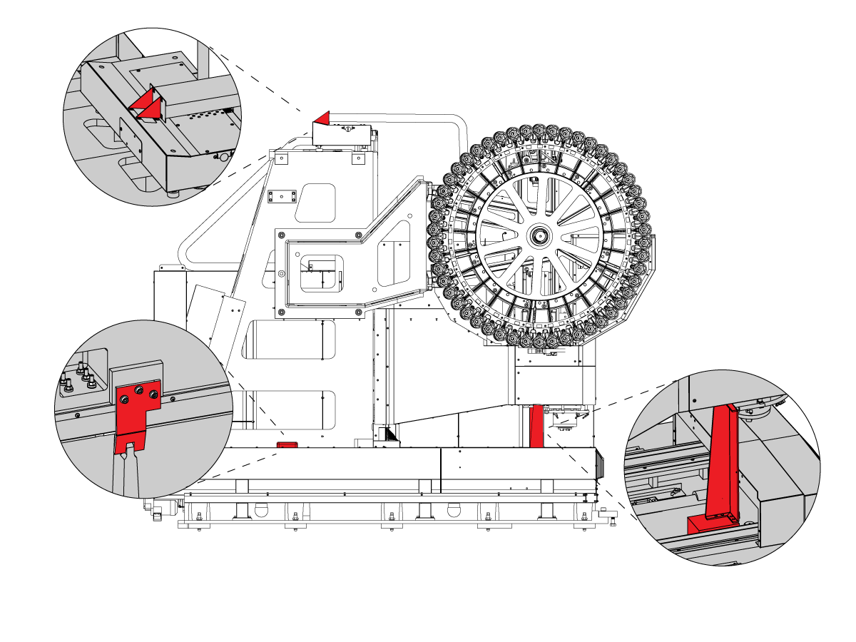
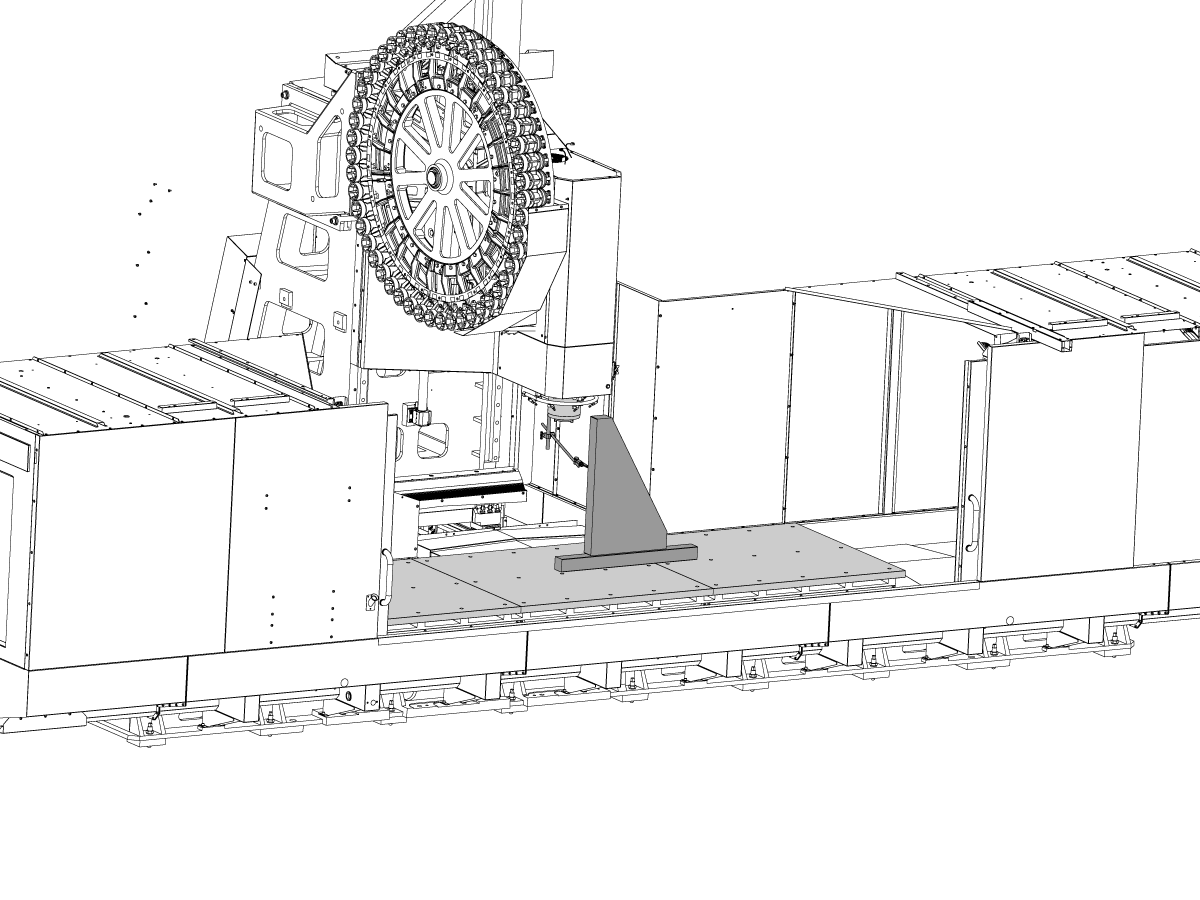
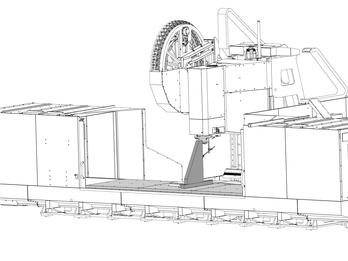
Remove the side panels from under the tool changer.

Clean the mating surface for the tool changer [1].

Place a piece of cardboard between the spindle head and the tool changer to prevent scratching the spindle head covers.


2

Note: Some components of the Carousel where removed for illustration purpose only.

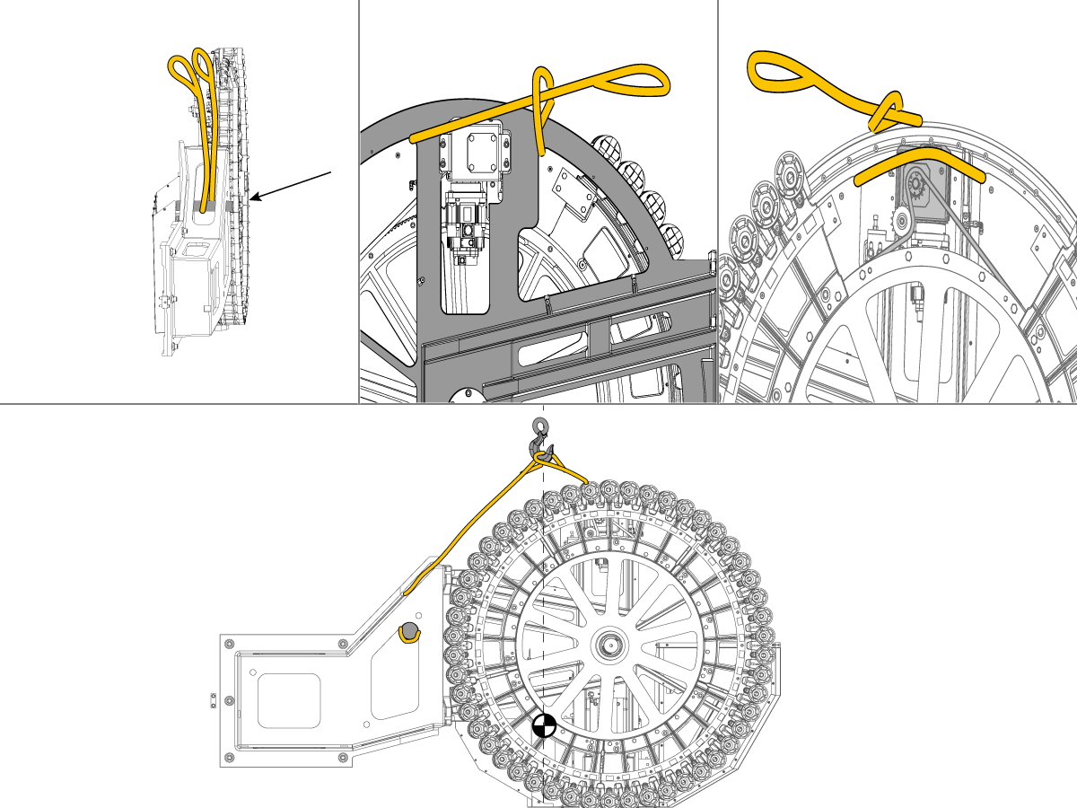
Using the proper lifting equipment and lifting straps (2x) as shown to support the tool changer (aprox. 2670 lbs / 1211 kg).

Unbolt [2] the tool changer from the shipping location and lift it into position on the column and tighten the (6) bolts to 80 ft-lb (108 Nm).

Machine Placement

1

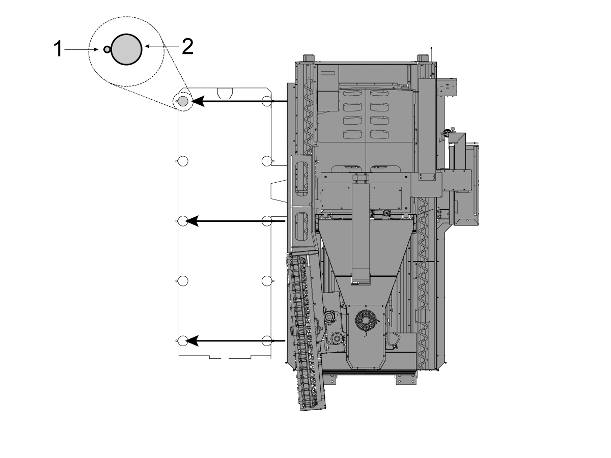
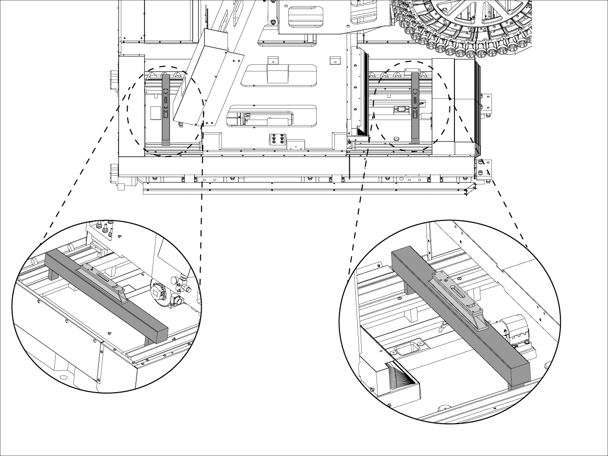
Important: Ensure the anchoring preparations are in accordance with the anchoring instructions prior to setting the machine in place. Image [1] Anchor hole [2] Leveling Pad

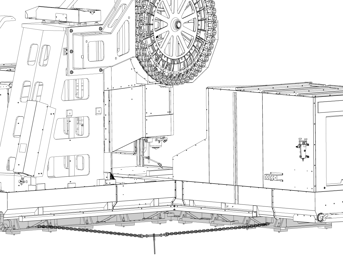
Place the column base assembly in position on the following leveling screws.

  • 1 - 2
  • 4 - 26
  • 6 - 24

Rough level by measuring from the floor to the bottom of the base 3". (4 - 4 1/2 inches for Conveyor Option). 

This will ensure that the final leveling procedure will go more quickly and that the coolant tank will properly fit beneath the coolant discharge. Loosely screw the jam nuts onto the leveling screws.

2

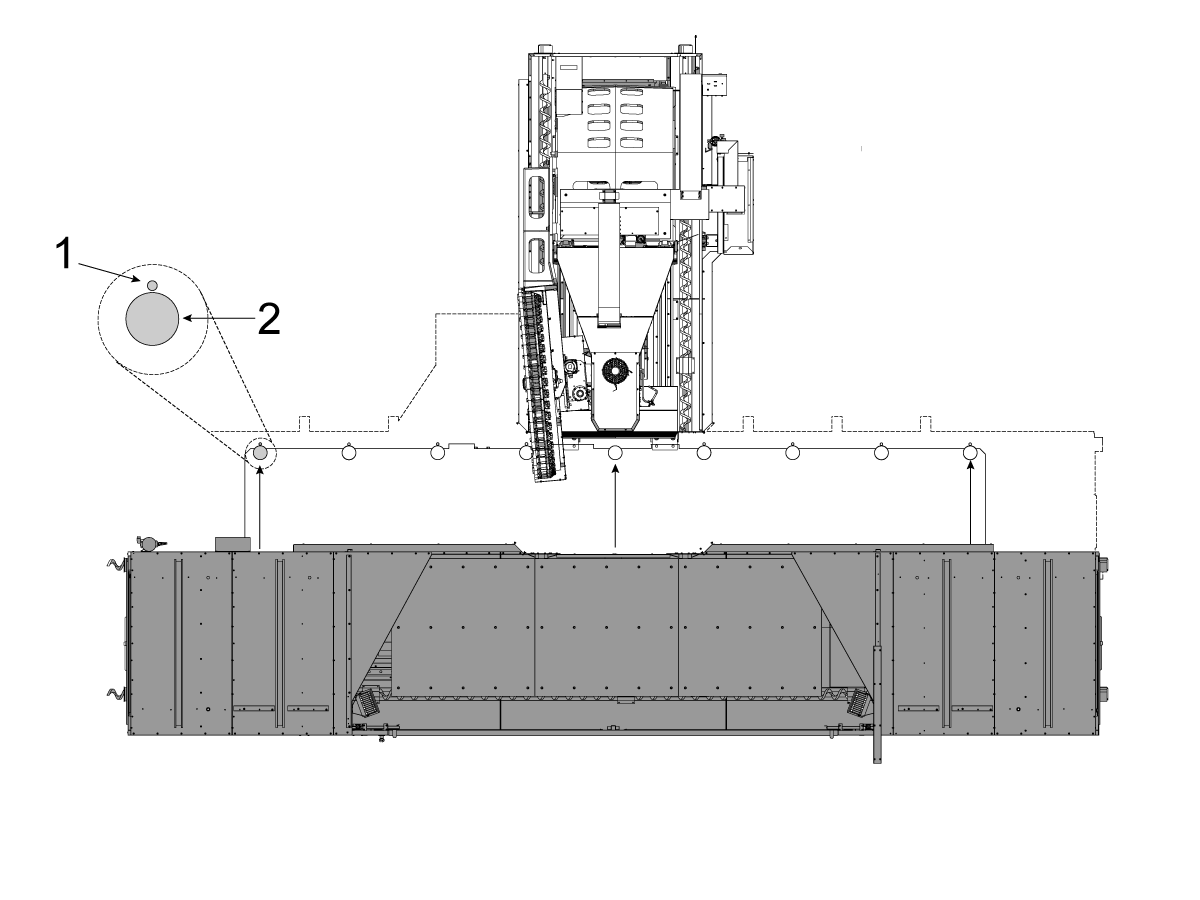
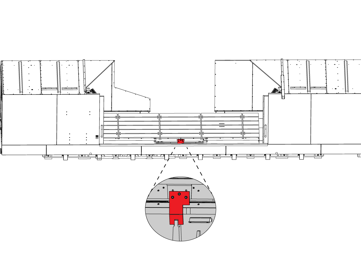
Place the table base assembly in position on the following leveling screws.. When placing the table base in position with respect to the column base, it is important that the two mating flanges be as parallel as possible (vertically and horizontally).

Rough level by measuring from the floor to the bottom of the base 3" (4 - 4 1/2 inches for Conveyor Option).  This will ensure that the final leveling procedure will go more quickly.

After rough leveling, verify that each of the screws are actually engaged in the threads, and that when the column base is in place and the mating surfaces are in contact that each.

3

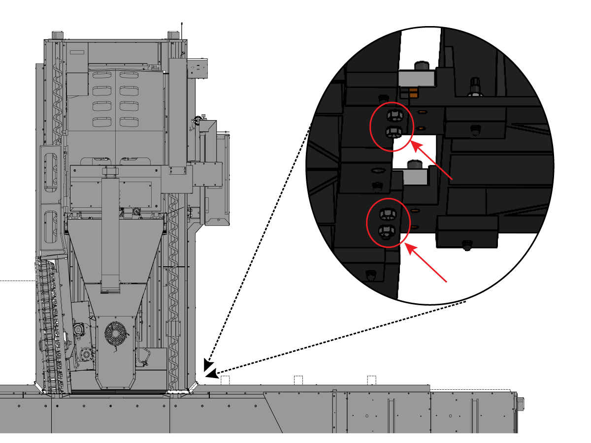
Be certain that the connecting screws are still free to rotate (do not leave the connecting bolts tight at this time because the machine still must be final leveled and squared)

INSTALL COUNTER BALANCE CYLINDER

1

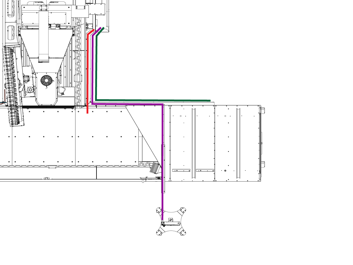
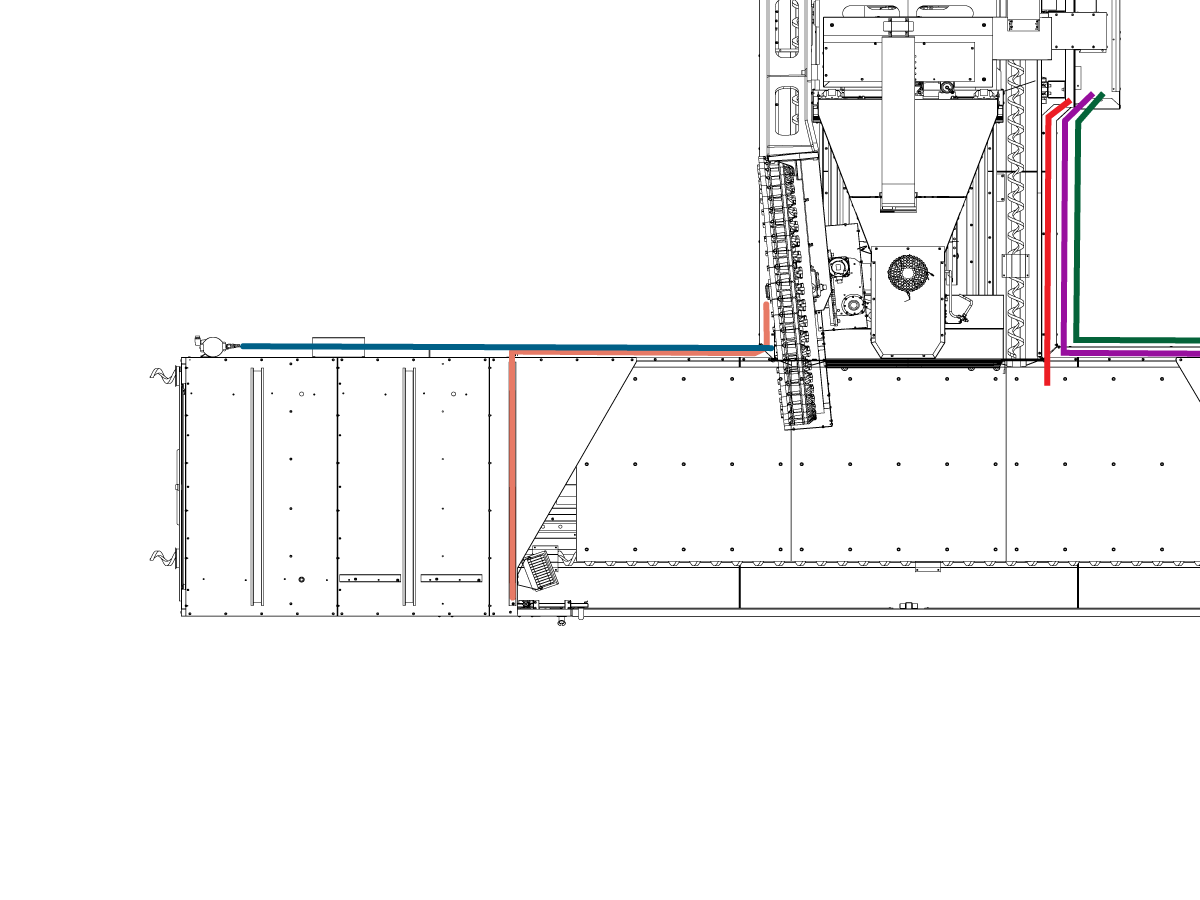
Note: The counterbalance cylinders have been removed (for overhead clearance during shipping), and they must be reinstalled and recharged with dry nitrogen prior to enabling the column axis

Re-install alignment collar and thrust bearing

  • Note orientation of alignment collar - deep shoulder faces rod end.

2

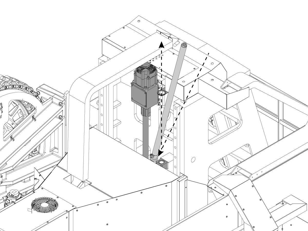
Insert the cylinder down between the spindle head casting and Column casting.

Slide the top of cylinder into the Rod Bracket until the bottom clears the Mount Block

Install cylinder assembly into mounting block on column 


3

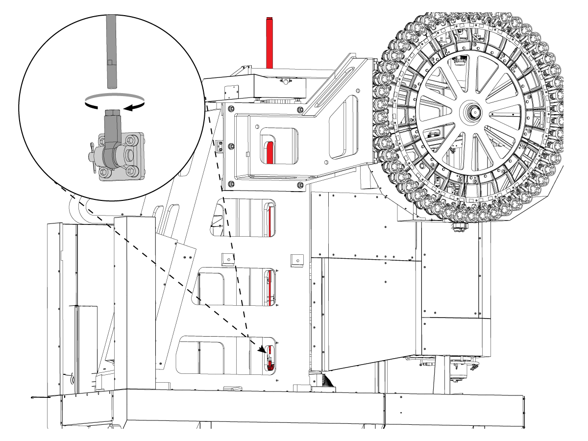
From the rear of the Column casting, extend cylinder rod and re- connect to the Rod End that is mounted on spindle head. 


4

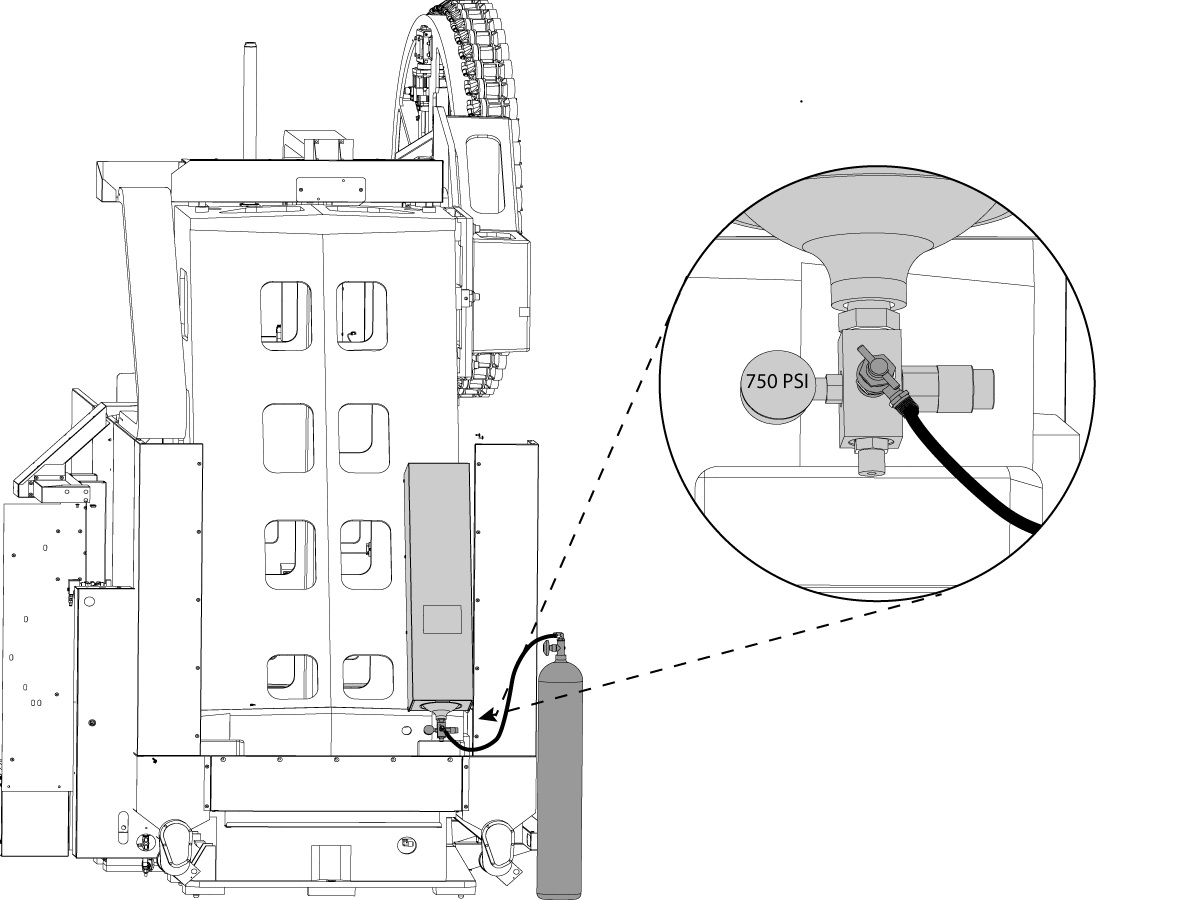
WARNING : Use appropriate PPE equipment (face shield, gloves, etc.) when filling the hydraulic tanks.

Make sure all tank valves are closed before beginning. 

Attach nitrogen tank fill nozzle

Begin filling counterbalance tank by SLOWLY cracking open the valve

Fill tank until gauge reads 750psi.
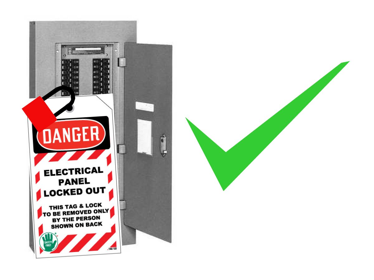
Wiring the Machine

1

Wiring the Column Base


  • On the electrical cabinet side, Locate the bundle of wires (Purple Line) containing 
    • Right Door sensor cable
    • Air line (Right Door Interlock)
    • Right Side work light
    • RJ45 SHIELDED CABLE
    • USB 2.0 CABLE
    • CBL740/770/+12V&GND-SKBIF EXT VS
    • Work light
  • Route cable through the cable channel along the base of the Column and Table assembly.
  • Continue up the rear panel of the Table assembly and over the top of the enclosure in the cable channel.
  • Connect the work light cable into the splitter connector 
  • Insert the air into the right Door Interlock and connect the Right Door Sensor
  • From the Front Panel connect the RJ45 SHIELDED CABLE, USB 2.0 CABLE and CBL740/770/+12V&GND-SKBIF EXT VS 
  • route the Air Line into Front Panel and connect to the quick connect for the air nozzle.


2

Wiring the Column Base (Continue)
  • On the Tool Changer Side locate the bundle of wires containing
    • Coolant Electrical connection bracket (Blue Line)
    • Left Door Sensor cable (Orange Line)
    • Air Line (Left Door Interlock) (Orange Line)
    • Left side work light (Orange Line)
  • Route cable and coolant lines through the cable channel along the base of the Column and Table assembly.
  • Split the Door and work light cable from the coolant lines, continue routing the door and work light cables up the rear panel of the Table assembly and over the top of the enclosure in the cable channel.
  • Connect the work light cable into the splitter connector 
  • Insert the air into the Left Door Interlock and connect the Left Door Sensor
  • Continue routing the Coolant Line through the cable channel and mount the coolant electrical connection bracket to the back of the enclosure panel

3

Wiring the Table Base

  • On the Table Base locate the bundle of cable (Red Line) containing 
    • X - axis motor / encoder cable
    • X - axis Linear Scale cable
    • X - axis lube lines (2x)
  • Route the cables through the cable channel located on the side of the Column base and into the bottom control wire box.
  • In the wire box find the X-axis linear scale interpolation box and connect the X axis linear scale cable
  • Route the X-axis motor / encoder cable up into the Electrical Cabinet 
  • Connect the X axis motor cable the Amplifier and route the X axis encoder cable up to the Main Processor (P1)
  • Locate the Chip Auger motor cable (Green line) in the cable channel  and route to the electrical cabinet. 
  • Connect auger motors to open locaion on QUAD CHIPC  PBC  (P4 - P7)

Removal of Rust Inhibitor

For ease of removal, first use a plastic scraper to remove most of the rust inhibitor and then use WD-40 or another PH neutral degreaser to spray all the way covers and other non-painted surfaces that have been coated with rust inhibitor. Let it soak for a few minutes before removing it. Then use shop towels to remove it. For thick applications of rust inhibitor use a plastic scraper to remove it.

: https://vimeo.com/haasautomation/review/171129636/7c2a5127f9

 Important: Do not use scotch-brite or metal scrapers, these will scratch the way covers. Furthermore, to avoid any contamination of the way cover seals with the sticky residue. Do not move any of the axes until all the rust inhibitor has been removed.

Electrical Connections

Danger: WORKING WITH ELECTRICAL SERVICES REQUIRED FOR A CNC ARE EXTREMELY HAZARDOUS. ALL POWER TO CNC MUST BE TURNED OFF LOCKOUT-TAGOUT AT THE SOURCE PRIOR TO CONNECTING THE LINE WIRES TO CNC. HOWEVER, IF THIS NOT THE CASE OR ARE NOT SURE HOW TO DO THIS, CHECK WITH APPROPIATE PERSONNEL OR OBTAIN THE NECESSARY HELP BEFORE CONTINUING. ALWAYS CHECK THE INCOMING LINES WITH AN AC VOLTAGE DETECTOR TO MAKE SURE POWER HAS BEEN DISCONNECTED.

1

Initial Control Inspection

Danger: At this point, there should be no electrical connection to the machine. Electrical panel must be closed and secured. When main switch is on, there is HIGH VOLTAGE throughout the electrical panel (including the circuit boards and logic circuits) and some components operate at high temperatures. Therefore, exercise extreme caution when working in the panel.

  • Set the main breaker switch at the upper right of the electrical panel on the back of the machine to OFF.
  • Using a screwdriver, unlock the two latches on the panel door, unlock the cabinet with the key and open the door.
  • Take sufficient time to check all the components and connectors associated with the circuit boards. Look for any cables that have become disconnected, look for any signs damage and loose parts in the bottom of the panel box. If there are any signs that the machine was mishandled, call the factory before proceeding.

2

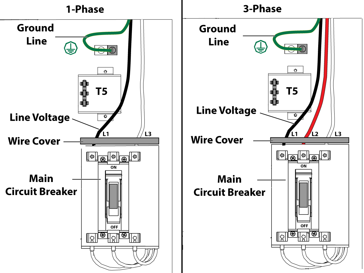
1-Phase Machines: Insert each power lead into the wire cover.  Connect the two power leads to L1 and L3 terminals on top of the main circuit breaker.

3-Phase Machines: Insert each power lead into the wire cover.  Connect the three power leads to L1, L2 and L3 terminals on top of the main circuit breaker.

Connect the separate ground line to the ground bus to the left of the terminals.

Refer to Haas Main CIrcuit Breaker - Torque Specifications for what value to torque the circuit breaker power leads.

 Note: Make sure that the leads actually go into the terminal-block clamps . (A poor connection will cause the machine to run intermittently or have other problems, such as servo overloads.) To check, simply pull on the wires after the screws are tightened.

3

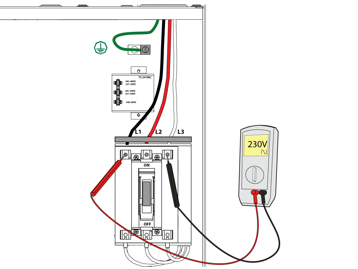
After the line voltage is connected to the machine, make sure that main circuit breaker (at top-right of rear cabinet) is OFF . Remove the Lockout / Tagout and Turn ON the power at the source. Using a digital voltmeter and appropriate safety procedures: 

1-Phase Machines: Measure the AC voltage across L1 & L3 at the main circuit breaker.  The AC voltage must be between 220 - 250 volts .
Note: Lower or higher than this voltage can generate low/high voltage alarms.

3-Phase Machines: Measure the AC voltage between all three pair phases at the main circuit breaker.  The AC voltage must be between 195 and 260 volts (360 and 480 volts for high voltage option).

 Note: Wide voltage fluctuations are common in many industrial areas; minimum and maximum voltage supplied to a machine while it is in operation must be known. U.S. National Electrical Code specifies that machines should operate with a variation of +5% to -5% around an average supply voltage. If problems with line voltage occur, or low line voltage is suspected, an external transformer may be used. If you suspect voltage problems, voltage should be checked every hour or two during a typical day to be sure it does not fluctuate more than +5% or -5% from an average.

4

Important: With the main circuit breaker turned OFF.

Check the transformer taps at the bottom-right corner of the rear cabinet.

1-Phase Machines: The input voltage cable must be moved to the connector which corresponds to the average voltage measured in the above step.

3-Phase Machines:  The input voltage cables labeled 74, 75, and 76 must be moved to the terminal block triple which corresponds to the average voltage measured in the above step.

5

Transformer T5 supplies 24VAC used to power the main contactor. There are two versions of this transformer for use on a 240 and 400V machines. The 240V transformer has two input connectors located about two inches from the transformer, which allow it to be connected to either 180-220V or 221-240V. Users that have 220V-240V RMS input power should use the connector labeled 221-240V, while users with 190-220V input power should use the connector labeled 180-220V. Failure to use the correct input connector will result in either overheating of the main contactor or failure to reliably engage the main contactor.

The 480V (option) T5 transformer has three input connectors, labeled 340-380V, 381-440V and 441-480V. Users with 340-380V 50Hz power should use the 340-380V connector while users with 380V-440V 50Hz power should use the 381-440V connector.

Important: Set the main circuit breaker to ON. Check for evidence of problems, such as the smell of overheating components or smoke. If such problems are indicated, immediately set the main circuit breaker to OFF and call the factory before proceeding.

After the power is on, measure the voltage across the bottom terminals on the main circuit breaker. It should be the same as the measurements where the input power connects to the main breaker. If there are any problems, check the wiring.

6

Apply power to the control by pressing the Power-On switch on the front panel.

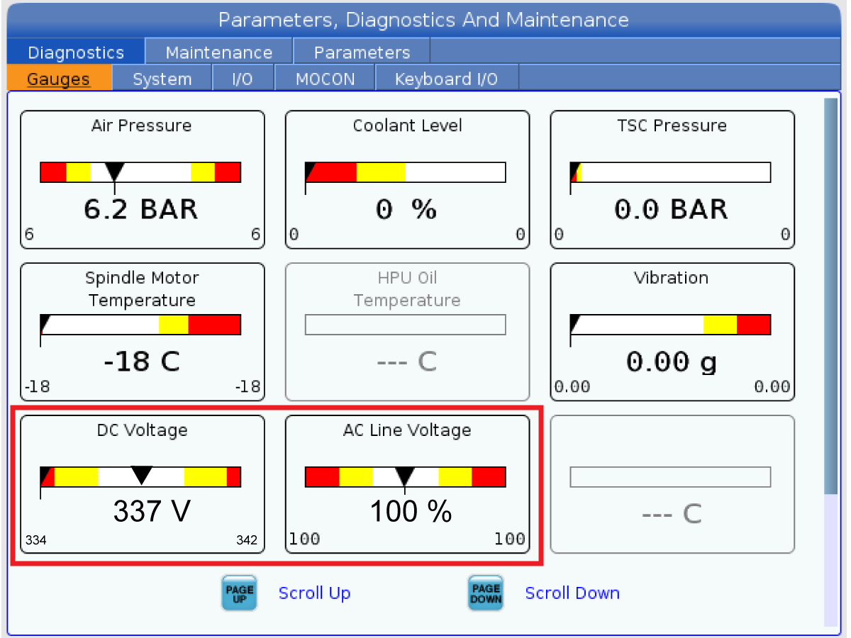
Check the DC Voltage and AC Line Voltage gauges in Diagnostics. The DC Voltage gauge must read between 310 - 360V. The AC Line Voltage must be between 90 and 105 percent. If the voltage is outside these limits, turn off the power and recheck steps 2 and 3. If the voltage is still outside these limits, call the factory.

7

Electrical power must be phased properly to avoid damage to your equipment. The Power Supply Assembly PC board incorporates a "Phase Detect" circuit with neon indicators. When the orange neon is lit (NE5), the phasing is incorrect. If the green neon is lit (NE6), the phasing is correct. If both neon indicators are lit, you have a loose wire; check the connections. Adjust phasing by setting the source power to off and then swapping L1 and L2 of the incoming power lines at the main circuit breaker.

Danger: ALL POWER TO CNC MUST BE TURNED OFF LOCKOUT-TAGOUT AT THE SOURCE PRIOR TO ADJUSTING PHASING. ALWAYS DOUBLE CHECK THE INCOMING LINES WITH AN AC VOLTAGE DETECTOR.

Turn off the power and set the main circuit breaker to OFF. Close the door, lock the latches, and turn the power back on.

Remove the key from the control cabinet and give it to the shop manager.

8

Activation

When the machine is properly placed and connected to both air and electrical power, it is ready for final installation (removing shipping blocks, leveling, spindle sweep, etc.) and software activation. The HFO service technician does this. Contact the local HFO to schedule the work.

Unblocking the Machine

1

Unblocking the Column Base


CAUTION: Before unblocking machine ensure that counterbalance cylinder charging hose is attached to nitrogen tank and nitrogen tank is fully charged to 750 psi.

  • Remove the shipping bracket and hardware completely from the side of column base on the Tool Changer side.
  • Handle jog (without zero return) the spindle head to the up position and support the bellows.
  • Remove the spindle shipping bracket 

2

Unblocking the Table Base

  • Remove the shipping bracket and hardware completely from the front of Table base 

Machine Leveling

Leveling the Machine

At this point the machine is completely unblocked and all axes are enabled. The process of leveling can now begin. The following criteria should have already been met at this point:

  • The machine correctly placed with respect to the anchoring points.
  • The rough leveling has taken place, ensuring that the bottom of the two bases are very close to 4 inches off the floor
  • The mating flanges of the two bases have been pulled into contact.
  • The screws that connect the two bases have been backed off and can rotate freely

1

Rough leveling the Column Base


  • Zero return all axes 3.
  • Move the Y-axis to the center of travel. 
  • With four leveling screws on the corners on the column base.
    • 1 - 2
    • 6 - 24
  • With the column at approximately center of travel, using gauge blocks lay one granite parallel across the linear guides as close to the table as possible and another granite parallel across the linear guides as near the rear of the machine as possible.
  • Place a level on each parallel and adjust the level of the column from side to side.
  • Check the freedom of the mating flange screws to be certain there is no binding.
  • On the guide nearest the control, place one level on the linear guide in front of the column and one level on the linear guide to the rear of the column. Adjust the level of the machine in the direction of Y-axis travel. Move the levels to the opposite linear guide and complete the process.
  • When the column base is level to earth in both directions, the six center leveling screws should be lowered to touch the leveling pads.
  • Remove the granite parallels from the column base.

2

Level of the Column Base

  • Handle jog the column to the rear.
  • Place a single level (T-2181 and T-2192) on the spindle, parallel to the X-axis of the machine. It is very unlikely that this surface will read zero; do not expect it to. Make note of the reading that is present.
  • While monitoring the level, move the column all the way forward and check if there is a change in the level reading. If there is no change in reading, then the column base has no twist. If there is a twist in the base, this must be corrected by using leveling feet 1,2,4 and 26.

3


Rough leveling the Table Base


  • Move the X-axis to the center of travel.
  •  Place two levels at right angles to each other as close as possible to the center of the table. One will show the level across the width of the table and the other will show the level along the length of the table.
  • Focus on leveling the table only in this X-axis position to establish a primary datum for the machine. Adjust only the four leveling screws: 7, 14, 16 and 23. 
  • When the table level is close to zero in both directions, the four very end leveling screws (10, 11, 19 and 20) may be brought down to touch the leveling pads.
  •  Continue to level the table base until both levels on the table read zero.

4

Sweeping the Table

  • Mounting the indicator on the spindle, first verify that the table is flat to the Y-axis plane.
  • Place a parallel granite (32") on the table surface. Sweep the granite in the Y-axis to determine, and correct column / table flatness in the Y-axis direction. This is a very sensitive measurement method and corrections to this flatness should be made in conservative steps.
  • Raise or lower the front of the table to get the flatness within specification using leveling screws 14 and 16.
  • Move the levels to the table and place them as close to the center as possible.
  • One level should be parallel to the X-axis and one level should be perpendicular to the X-axis.
  • Once the Column to Table flatness has been established, jog the X-axis and adjust the remaining leveling screws to maintain the current level reading.

5


level the Table 


  • Focus on leveling the table only in this X-axis plane to establish a primary datum from the granite. 
  • Make note of the reading that is present. 
  • While monitoring the level, jog the table all the way to left and check if there is a change in the level reading.
  • While monitoring the level, jog the table all the way to right and check if there is a change in the level reading.
  •  If there is no change of reading, then the column base has no twist. If there is a twist in the table, this must be corrected.
  •  the remaining leveling screws should be lowered to touch the leveling pads.

Geometry Check

1

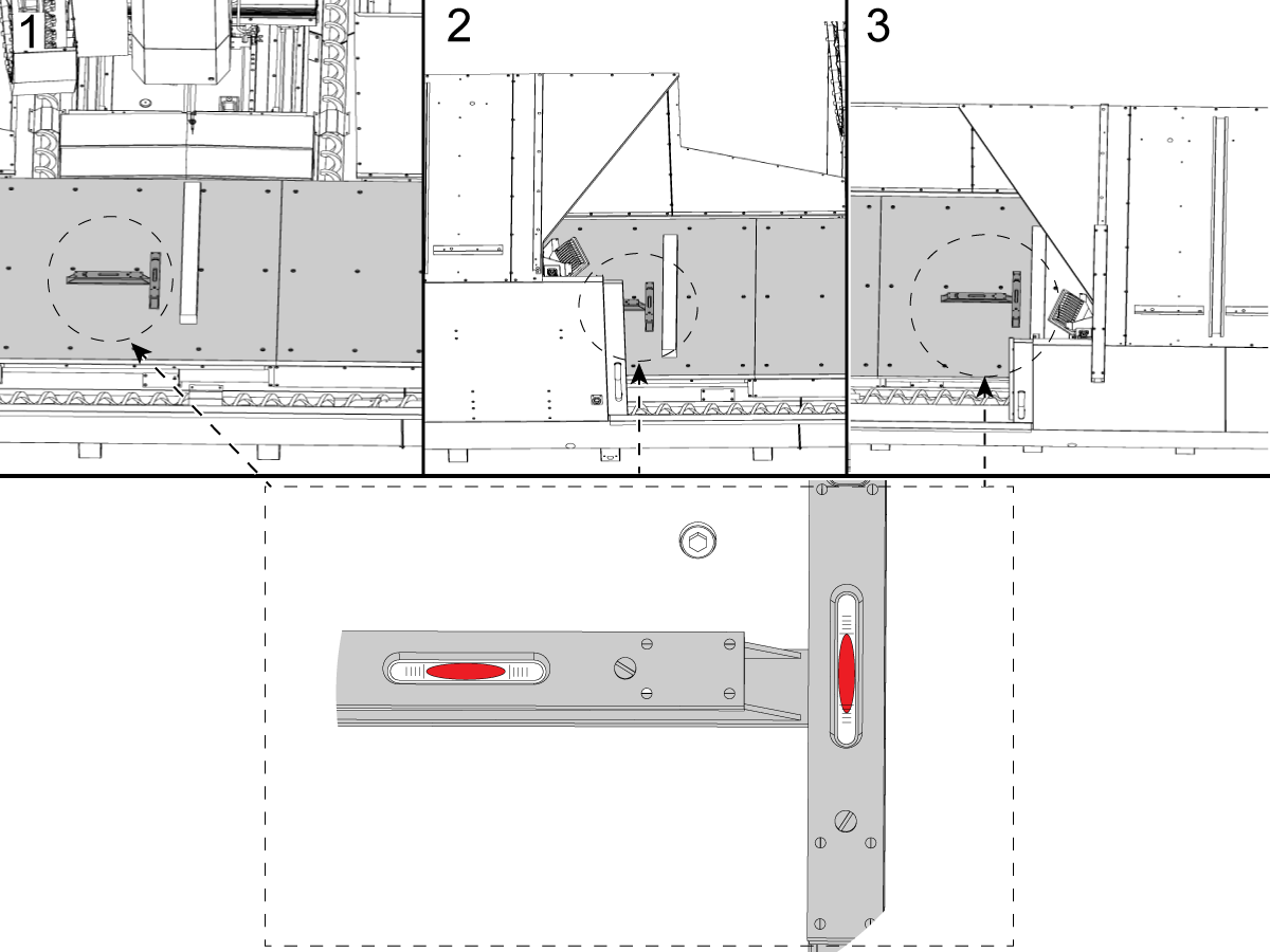
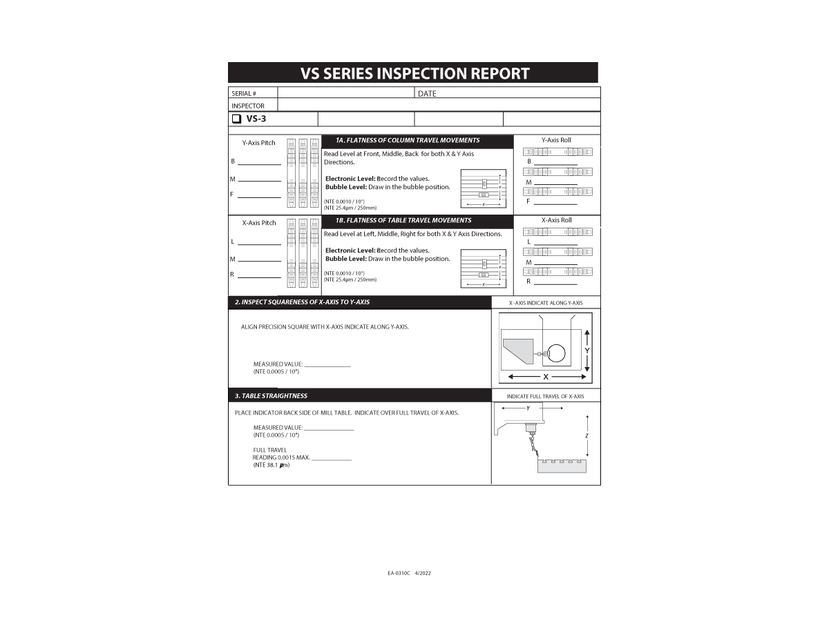
Every point of inspection must be verified to be within the tolerances specified for the machine. 

  • 1A. FLATNESS OF COLUMN TRAVEL MOVEMENTS
  • 1B. FLATNESS OF TABLE TRAVEL MOVEMENTS
  • 2. INSPECT SQUARENESS OF X-AXIS TO Y-AXIS
  • 3. TABLE STRAIGHTNESS
  • 4A. SQUARENESS OF Z-AXIS MOTION TO X-AXIS
  • 4B. SQUARENESS O F Z-AXIS MOTION TO Y AXIS
  • 5. SPINDLE SWEEP
  • 6A. SPINDLE RUNOUT AT TAPER
  • 6B. SPINDLE RUNOUT ON TEST TOOL BAR
  • 7. PARALLELISM OF TABLE TO X - Y MOTION

2

Two fundamental geometry checks need to be made. The first is the perpendicularity of the X-axis to the Y-axis, and the second is to verify the sweep of the Z-axis.

  • The sweep of the X-axis to the Y-axis is accomplished using a granite square. Set zero by sweeping the Y-axis on one side of the square, and then to verify that the motion of the X-axis is perpendicular by sweeping the adjacent side of the square. If the X-axis and Y-axis are not found to be within tolerance, between the mating flange surfaces that is creating this error.

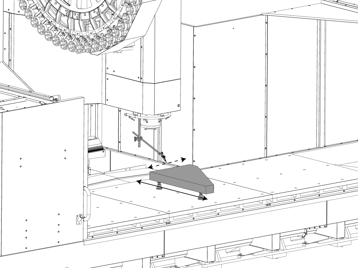
Observe readings and adjust base to saddle perpendicularity as follows:

  • Route ratchet straps from both sides of base to ends of saddle, looping through casting holes.
  • Remove slack from both straps without over tightening.
  • Gently tighten the appropriate strap observing reading changes on indicator.
  • Continue making slight adjustments with straps and repeat granite sweeps until perpendicularity reading is within traveler specifications - record readings.

3

Verify the sweep of the Y/Z-axis:

  • Sweeping the Z-axis is accomplished using a cylinder square. 
  • The line of motion of the Z-axis will be checked by comparing it to the line of intersection of the two most convenient relative planes, that of the X-Z plane and the Y-Z plane.
  •  By assuring that each of these planes are perpendicular to the X-Y plane within specification, the machine geometry will be preserved. 

Observe readings and adjust the needed Column Base leveling screws:


  • X-Z plane: 
    • Adjust the left / right leveling screw evenly up or down to bring the reading within specification.
  • Y-Z plane:
    • Adjust the rear leveling screw evenly up or down to bring the reading within specification.

Final Connection of the Column Base to the Table Base

  • Before tightening all the connecting screws, recheck the table level to be certain that the squaring process of the column base did not affect table level.
  • Torque the connecting screws with lock washers in place to 400 ft-lb. 


Anchoring the Machine in Place

NOTE: Ensure the anchoring preparations are in accordance with the anchoring instructions prior to setting the machine in place


1

  • Complete the machine installation, install the anchor bolts and tightening to 25 ft-lb. 
  • Repeat of the basic leveling procedure and a recheck of the geometry to be done. All criteria must be met.


Completing the Installation

1

  1.  Seal the shipping bracket bolt holes to prevent oil leaks.
  2.  Replace all sheet metal removed paying particular attention to sealing any component mating surface potentially exposed to coolant flow.
  3. Verify alignment and operation of the tool changer.
  • Using a split tool in RECOVERY mode, verify the alignment to the pocket and check the alignment to the spindle.
  • With the (4) TC bolts loose support the weight of the tool changer, use the jacking screws for the SMTC adjuster to align the front-to-back of the arm to the spindle. The tool changer will not move unless you support the weight.
  • If the spindle alignment is out side-to-side, insert a shim between the tool changer and the mount. Do not leave the shim exposed

4. Verify all machine functions.

寻找经销商
反馈
Haas Logo

美元价格不包括关税、报关费用、保险费、增值税及运费。
USD prices DO NOT include customs duty, customs fees, insurance, VAT, or freight.

人民币价格包含关税、报关费用、货运保险和增值税, 但不包括运费。
CNY prices include customs duty, customs fees, insurance, and VAT. DOES NOT include freight.

Haas 交付价格

此价格包含运费、出口和进口关税、保险费以及任何在运送至与您(买家)商定的位于法国的某一地点的过程中产生的其他费用。在 Haas 数控产品的交付中不会添加任何其他强制性费用。

随时掌握 HAAS 最新提示和技术……

立即注册!   

HAAS TOOLING ACCEPTS THE FOLLOWING:

  • 服务及支持
  • 所有者
  • 申请售后
  • 操作员手册
  • Haas 零件
  • 转台维修申请
  • 预装指南
  • 采购指南
  • 全新 Haas 机床配置和价格
  • 可用存货
  • Haas 价目表
  • CNCA 金融计划
  • 关于 Haas
  • 招贤纳士
  • 认证与安全
  • 联系我们
  • 历史记录
  • 条款和条件
  • Haas Tooling 条款和条件
  • 隐私
  • 保修期
  • Haas 社区
  • Haas 认证计划
  • Haas 赛车运动
  • Gene Haas 基金会
  • Haas 技术教育社区
  • 最新活动
  • 加入对话
  • Facebook
  • Twitter
  • Flickr
  • YouTube
  • LinkedIn
  • Instagram
  • TikTok
© 2023 Haas Automation, Inc - CNC 机床

This site is protected by reCAPTCHA and the Google Privacy Policy and Terms of Service apply.


2800 Sturgis Rd., Oxnard, CA 93030 / Toll Free: 800-331-6746
Phone: 805-278-1800 / Fax: 805-278-2255

Cookie 通知

我们使用 Cookie 来改善您的用户体验. 我们的 Cookie 通知 描述我们使用哪些 cookie、为什么使用它们以及如何找到有关它们的更多信息。请确认您同意我们使用 Analytics Cookie。如果您不同意,您仍然可以使用我们的网站,但用户体验降低。

管理设置

Cookie 通知

我们使用 Cookie 来改善您的用户体验. 我们的 Cookie 通知 描述我们使用哪些 cookie、为什么使用它们以及如何找到有关它们的更多信息。请确认您同意我们使用 Analytics Cookie。如果您不同意,您仍然可以使用我们的网站,但用户体验降低。

Functional Cookies

Analytics Cookies