MyHaas Bienvenido:
!
Haas Tooling Historial de órdenes de invitados MyHaas/HaasConnect Iniciar sesión Registrar Haas Tooling Mi cuenta Order History Return History MyHaas/HaasConnect Cerrar sesión Bienvenido: Mis máquinas Última actividad Mis presupuestos Mi cuenta Mis usuarios Cerrar sesión
Encuentre su distribuidor
  1. Seleccionar idioma
    1. English
    2. Deutsch
    3. Español - España
    4. Español - Méjico
    5. Français
    6. Italiano
    7. Český
    8. Nederlands
    9. Magyar
    10. Polski
    11. Svenska
    12. 中文
    13. Suomi
    14. Norsk
    15. الإنجليزية
    16. български
    17. Hrvatski
    18. Ελληνικά
    19. Slovenský
    20. Slovenščina
    21. 한국어
    22. 日本語
Search
  • máquinas Main Menu
    • Fresadoras verticales de Haas Fresadoras verticales
      Fresadoras verticales
      Fresadoras verticales Ver todo
      • Fresadoras verticales
      • Serie VF
      • Máquinas universales
      • Series VR
      • VMC con cambio de paletas
      • Mini Mills
      • Máquinas de moldeo
      • Serie de taladrado/roscado/fresado
      • Fresadoras Toolroom
      • Fresadoras compactas
      • CMV portico router serie GR y GM
      • CMV de gran tamaño
      • Fresadora de sobremesa
      • Simulador del control
      • Cargador automático de piezas de fresadora
      • Cargador automático de piezas compacto
    • Product Image Soluciones multieje
      Soluciones multieje
      Soluciones multieje Ver todo
      • Soluciones multieje
      • Tornos con eje Y
      • Fresadoras de 5 ejes
    • Tornos Haas Tornos
      Tornos
      Tornos Ver todo
      • Tornos
      • Serie ST
      • Doble husillo
      • Tornos Toolroom
      • Torno con plato de garras
      • Alimentador de barras Haas V2
      • Cargador automático de piezas de torno
    • Fresadoras horizontales Haas Fresadoras horizontales
      Fresadoras horizontales
      Fresadoras horizontales Ver todo
      • Fresadoras horizontales
      • Cono ISO 50
      • Cono ISO 40
    • Mesas giratorias y divisores Haas Mesas giratorias y divisores
      Mesas giratorias y divisores
      Mesas giratorias y divisores Ver todo
      • Mesas giratorias y divisores
      • Mesas giratorias
      • Divisores
      • Equipos giratorios de 5 ejes
      • Equipos rotativos extragrandes
    • Product Image Sistemas de automatización
      Sistemas de automatización
      Sistemas de automatización Ver todo
      • Sistemas de automatización
      • Paquetes de robot
      • Cargadores automáticos de piezas
      • Sistemas Pallet Pool
      • Alimentador de barras Haas
      • Models
    • ENLACES RÁPIDOS Serie especial  Serie especial 
      OPORTUNIDADES LABORALES EN HAAS OPORTUNIDADES LABORALES EN HAAS CONFIGURACIÓN Y PRECIO CONFIGURACIÓN Y PRECIO LISTA DE PRECIOS LISTA DE PRECIOS NOVEDADES NOVEDADES SU PRIMERA MÁQUINA CNC SU PRIMERA MÁQUINA CNC HAAS SIX PACK HAAS SIX PACK
      COMPRAR HERRAMIENTAS
      • Configure y sepa el precio de su máquina Haas
      • Lista de precios
      • Inventario disponible
      • Financiación CNCA
      ¿QUIERE HABLAR CON ALGUIEN?

      En las tiendas Haas Factory Outlet (HFO) pueden resolver sus dudas y orientarlo sobre las mejores opciones.

      CONTACT YOUR DISTRIBUTOR >
  • Opciones Main Menu
    • Product Image Husillos
      Husillos
      Husillos Ver todo
      • Husillos
    • Product Image Cambiadores de herramientas
      Cambiadores de herramientas
      Cambiadores de herramientas Ver todo
      • Cambiadores de herramientas
    • Product Image 4.º | 5.º eje
      4.º | 5.º eje
      4.º | 5.º eje Ver todo
      • 4.º | 5.º eje
    • Product Image Torretas y herramientas motorizadas
      Torretas y herramientas motorizadas
      Torretas y herramientas motorizadas Ver todo
      • Torretas y herramientas motorizadas
    • Product Image Palpado
      Palpado
      Palpado Ver todo
      • Palpado
    • Extracción de virutas y refrigeración de Haas Tratamiento de refrigerante y virutas
      Tratamiento de refrigerante y virutas
      Tratamiento de refrigerante y virutas Ver todo
      • Tratamiento de refrigerante y virutas
    • El Control Haas El Control Haas
      El Control Haas
      El Control Haas Ver todo
      • El Control Haas
    • Product Image Opciones para productos
      Opciones para productos
      Opciones para productos Ver todo
      • Opciones para productos
    • Product Image Herramientas y utillaje
      Herramientas y utillaje
      Herramientas y utillaje Ver todo
      • Herramientas y utillaje
    • Product Image Portapiezas
      Portapiezas
      Portapiezas Ver todo
      • Portapiezas
    • Product Image Soluciones de 5 ejes
      Soluciones de 5 ejes
      Soluciones de 5 ejes Ver todo
      • Soluciones de 5 ejes
      • 5 Easy Steps to 5-Axis
    • Product Image Automatización
      Automatización
      Automatización Ver todo
      • Automatización
    • ENLACES RÁPIDOS Serie especial  Serie especial 
      OPORTUNIDADES LABORALES EN HAAS OPORTUNIDADES LABORALES EN HAAS CONFIGURACIÓN Y PRECIO CONFIGURACIÓN Y PRECIO LISTA DE PRECIOS LISTA DE PRECIOS NOVEDADES NOVEDADES SU PRIMERA MÁQUINA CNC SU PRIMERA MÁQUINA CNC HAAS SIX PACK HAAS SIX PACK
      COMPRAR HERRAMIENTAS
      • Configure y sepa el precio de su máquina Haas
      • Lista de precios
      • Inventario disponible
      • Financiación CNCA
      ¿QUIERE HABLAR CON ALGUIEN?

      En las tiendas Haas Factory Outlet (HFO) pueden resolver sus dudas y orientarlo sobre las mejores opciones.

      CONTACT YOUR DISTRIBUTOR >
  • Why Haas Main Menu
      Descubra la diferencia Haas
    • Por qué Haas
    • MyHaas
    • Comunidad de educación
    • Industria 4.0
    • Certificado Haas
    • Testimonios de clientes
  • Servicio Main Menu
      Bienvenido al servicio Haas
      INICIO DE SERVICIO Manuales del operador Procedimientos instructivos Guías de resolución de problemas Mantenimiento preventivo Recambios Haas Haas Tooling Vídeos
  • Vídeos Main Menu
  • Herramientas de Haas Main Menu
      Portaherramientas de fresadora Amarre de pieza de fresadora Fresado Herramientas de tornos Portaherramientas de torno AMARRE DE PIEZAS DE TORNOS Platos de pinza ER Hacer agujeros Roscado Brocas Cambio de herramientas Accesorios de herramientas Abrasivos Kits de paquetes Vestuario y accesorios Almacenamiento y manipulación Medición e inspección
    • Haas Tooling
    • Portaherramientas de fresadora
      Portaherramientas de fresadora Shop All
      • Portafresas
      • Soportes de plato de fresado
      • Soportes de ajuste por contracción
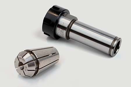
      • Pinzas de sujeción ER
      • Mandriles de fresado y pinzas
      • Portabrocas para taladros
      • Tiradores
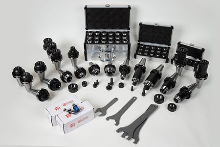
      • Kits de portaherramientas de fresadoras
      • Mandriles de fresado y pinzas hidráulicos
    • Amarre de pieza de fresadora
      Amarre de pieza de fresadora Shop All
      • Tornos de banco de garra fija
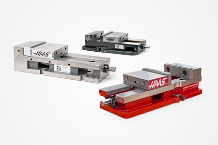
      • Tornos de banco con centrado automático
      • Placas adaptadoras
      • Mandíbulas de torno de banco de fresa
      • Accesorios de amarre de pieza
      • Kits de torno de banco
      • Paralelas de torno de banco
      • Plato de garras HA5C
      • Kits de torno de banco giratorio
    • Fresado
      Fresado Shop All
      • Cuerpos de plato de fresado
      • Insertos de fresado
      • Fresadoras frontales
      • Insertos y fresas de chaflán
      • Cuerpos de fresa de punta indexables
      • Fresas de punta esférica
      • Fresas de chaflán
      • Fresas de desbaste
      • Insertos y fresas de punta de bola indexables
      • Kit de plato de fresado
      • Kits de fresas de chaflán
      • Kits de fresas de punta divisibles
      • Herramientas de corte con cola de milano
      • Herramientas de corte de cola de milano indexables
      • Engrabado de fresas de punta
      • Rebabas
      • Fresas para redondeado de esquinas
    • Herramientas de tornos
      Herramientas de tornos Shop All
      • Herramientas de corte
      • Kits de herramientas de corte
      • Insertos de torneado
      • Herramientas de ranurado
      • Herramientas de roscado y ranurado con DI pequeño
      • Insertos de roscado
      • Portaherramientas de roscado
      • Portaherramientas ID
      • Portaherramientas OD
      • Insertos de torneado de cermet
      • Insertos de torneado CBN
      • Insertos de roscado y ranura de Haas Notch
      • Portaherramientas para roscado y ranurado Haas Notch
    • Portaherramientas de torno
      Portaherramientas de torno Shop All
      • Portaherramientas TL y CL
      • Portaherramientas BOT
      • Portaherramientas BMT
      • Portaherramientas eléctricas
      • Manguitos reductores
      • Portaherramientas VDI
    • AMARRE DE PIEZAS DE TORNOS
      AMARRE DE PIEZAS DE TORNOS Shop All
      • Centros activos
      • Tubos guía del husillo
      • Pinzas de cambio rápido
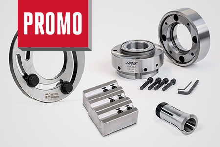
      • Pinzas de sujeción para torno
      • Pinzas 5C
      • Kits de pinzas 5C
      • Aros de mandrinar para torno
      • Garras de torno
    • Pinzas y mandriles ER
      Pinzas y mandriles ER Shop All
      • ER Collets
      • Pinzas selladas ER
      • Pinzas de rosca ER
      • Accesorios y juegos de pinzas ER
      • Pinzas de sujeción ER
      • Pinzas de sujeción ER con mango recto
      • Portabrocas para talados sin llave de mango recto
    • Hacer agujeros
      Hacer agujeros Shop All
      • Brocas de carburo
      • Cuerpos de broca indexables
      • Insertos de broca indexable
      • Cuerpos de broca modular
      • Cabezas de broca modular
      • Juegos y brocas de cobalto
      • Brocas de centro
      • Escariadores
      • Kits de taladrado indexable
      • Taladros de puntos
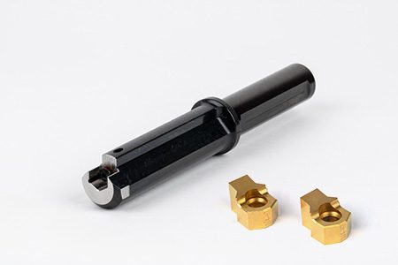
      • Cuerpos de la broca de pala
      • Insertos de la broca de pala
      • Brocas de avellanado
    • Roscado
      Roscado Shop All
      • Machos de roscar
      • Insertos de roscado
      • Portaherramientas de roscado
      • Fresas de rosca
      • Roscas para tubos
      • Kits de taladrado y roscado
    • Brocas
      Brocas Shop All
      • Portaherramientas de brocas
      • Insertos para brocas
    • Cambio de herramientas
      Cambio de herramientas Shop All
      • Máquinas de medición de herramientas
      • Máquinas de ajuste por contracción
    • Accesorios de herramientas
      Accesorios de herramientas Shop All
      • Limpiador de cono de husillo
      • Elevador de taller Haas
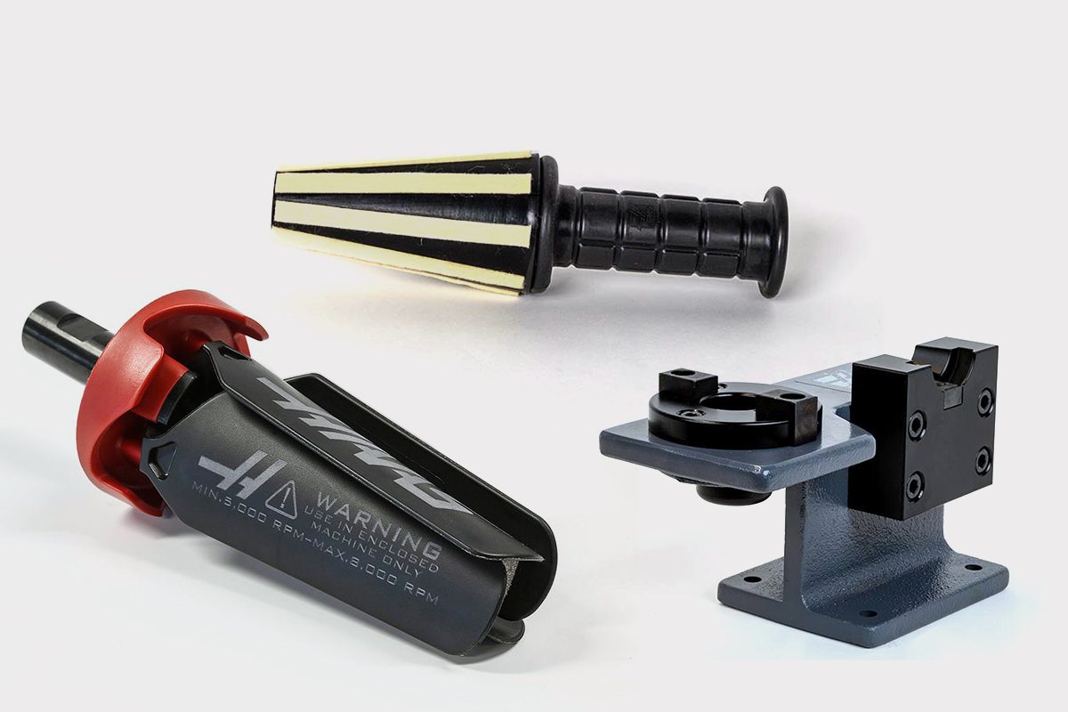
      • Utillajes de portaherramientas
      • Ruedas de desbarbado
      • Ventiladores de limpieza de CNC
    • Abrasivos
      Abrasivos Shop All
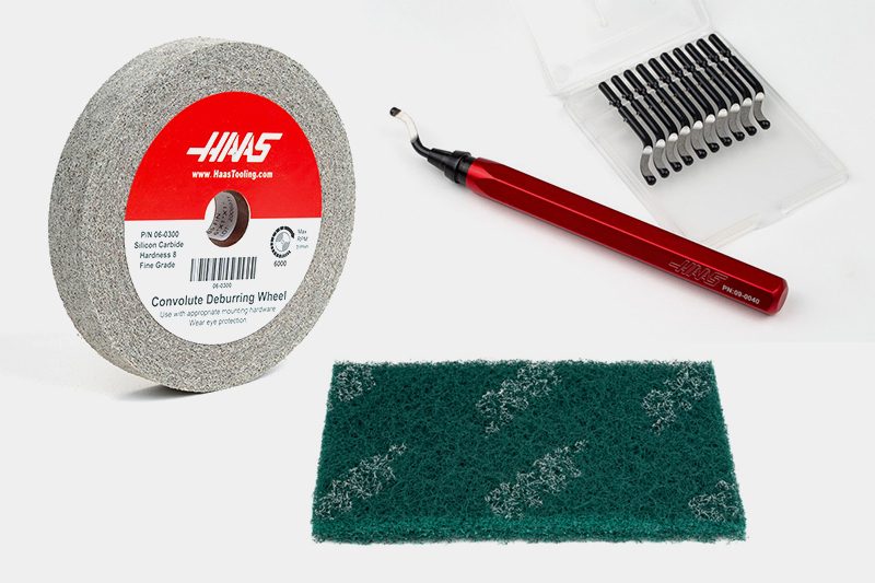
      • Almohadillas abrasivas
      • Herramientas de desbarbado
      • Ruedas de desbarbado
    • Kits de paquetes
      Kits de paquetes Shop All
      • Kits de ventilador de limpieza de virutas
      • Kits de herramientas de corte
      • Kits de fresas de punta divisibles
      • Kits de herramientas de corte
      • Kits de taladrado y roscado
      • Kits de taladrado indexable
      • Kit de plato de fresado
      • Kits de fresas de chaflán
      • Kits de portaherramientas de fresadoras
      • 08-1769
      • 08-1766
      • 08-1767
      • 08-1768
      • 08-1787
      • 08-1788
      • 08-1789
      • 08-1784
      • 08-1785
      • Kits de amarre de pieza
      • Kits de torno de banco giratorio
      • Kits de torno de banco
    • Almacenamiento y manipulación
      Almacenamiento y manipulación Shop All
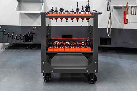
      • Carros de herramientas
    • Medición e inspección
      Medición e inspección Shop All
      • Kit de medición de 7 piezas
      • Estiletes WIPS, paquete de 3
      • Lápiz óptico de repuesto de WIPS
      • Barra de prueba de husillo
      • Refractómetro para refrigerante
      • Calibre de fuerza de fijación
    • Vestuario y accesorios
      Vestuario y accesorios Shop All
      • Accesorios
      • Ropa
    • ENLACES RÁPIDOS DE HAAS TOOLING
      PRODUCTOS NUEVOS PRODUCTOS NUEVOS
      EL MÁS POPULAR EL MÁS POPULAR
      PROMOCIONES DE HERRAMIENTAS PROMOCIONES DE HERRAMIENTAS
      FINANCIACIÓN Y PLAZOS ABIERTOS FINANCIACIÓN Y PLAZOS ABIERTOS
      Preguntas frecuentes Preguntas frecuentes
      KITS CREADOS PARA USTED KITS CREADOS PARA USTED
  • Póngase en contacto con nosotros

×

Resultados de la búsqueda

Web Pages

Imágenes

    • <
    • 1
    • >
MyHaas Bienvenido:
!
Haas Tooling Historial de órdenes de invitados MyHaas/HaasConnect Iniciar sesión Registrar Haas Tooling Mi cuenta Order History Return History MyHaas/HaasConnect Cerrar sesión Bienvenido: Mis máquinas Última actividad Mis presupuestos Mi cuenta Mis usuarios Cerrar sesión
Encuentre su distribuidor
  1. Seleccionar idioma
    1. English
    2. Deutsch
    3. Español - España
    4. Español - Méjico
    5. Français
    6. Italiano
    7. Český
    8. Nederlands
    9. Magyar
    10. Polski
    11. Svenska
    12. 中文
    13. Suomi
    14. Norsk
    15. الإنجليزية
    16. български
    17. Hrvatski
    18. Ελληνικά
    19. Slovenský
    20. Slovenščina
    21. 한국어
    22. 日本語
Search
×

Resultados de la búsqueda

Web Pages

Imágenes

    • <
    • 1
    • >

VS-Series- Installation - NGC

Inicio de servicio Procedimientos técnicos VS-Series - Installation - NGC
Recently Updated Last updated: 10/27/2022

VS-Series - Installation - NGC

Revision 1


Under Construction

VS-Series - Installation - NGC

- Saltar a la sección - 1. Introduction (1 paso) 2. Leveling Screws Hardware 3. Leveling Overview 4. Tool Changer Installation (2 pasos) 5. Machine Placement (3 pasos) 6. INSTALL COUNTER BALANCE CYLINDER (4 pasos) 7. Wiring the Machine (3 pasos) 8. Removal of Rust Inhibitor 9. Electrical Connections 10. Unblocking the Machine (2 pasos) 11. Machine Leveling (5 pasos) 12. Geometry Check (3 pasos) 13. Final Connection of the Column Base to the Table Base 14. Anchoring the Machine in Place (2 pasos) 15. Completing the Installation (1 paso) Back to Top

Introduction

1

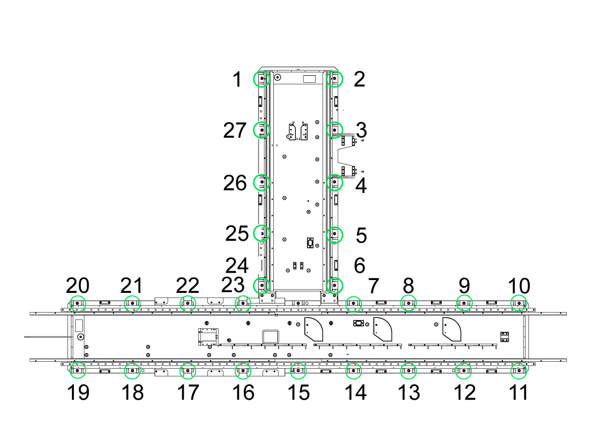
Use these numbers to identify which foot to adjust.

  • Prerequisites:

Adjust each leveling screw until the base is 4" (10 cm) above the floor (3" (76 mm) leveling pad height plus 1" (25 mm) of screw below the bottom of the pad).

 Note: The condition of the foundation may require different heights at some leveling screws to make the machine level.

  Important: it is required that the machine be anchored. Refer to the following link: ANCHORING INSTRUCTIONS.

  • Using the anchor pattern from Machine Layout to mark the machine location.
  • Print the anchor footprint from AD0456 to mark anchor location.
    • Important: Footprint must be printed at 1:1 ratio


Tools Required:

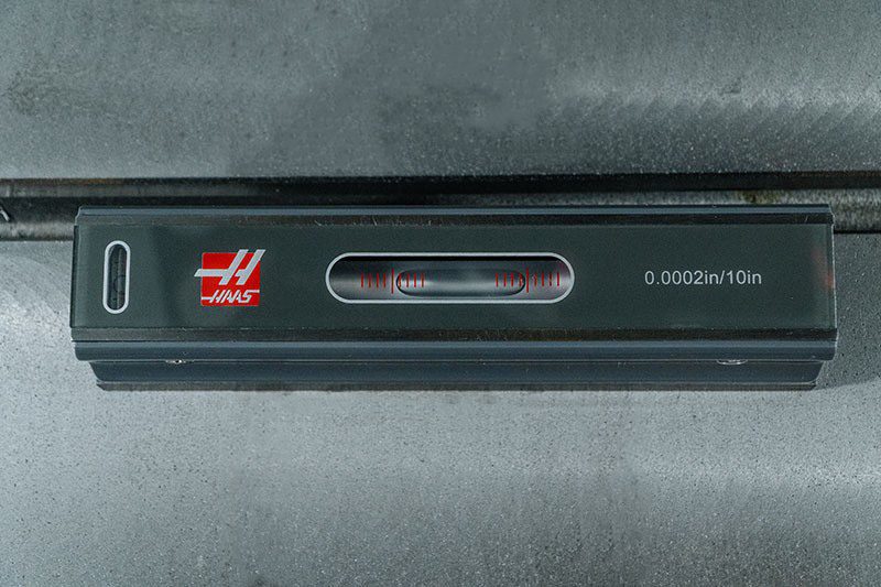
  • Electronic differential level, precision bubble level, calibrated to show 0.0005 inch per 10"
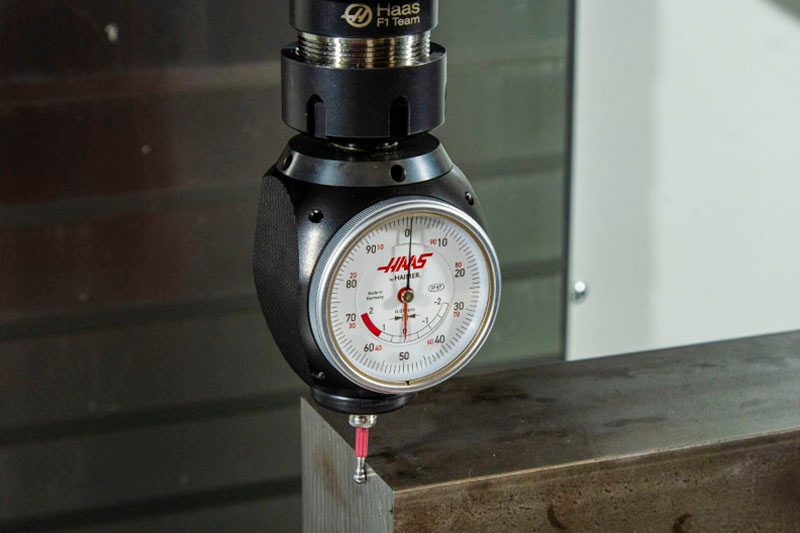
  • Test indicator (0.0005")
  • Two ¾" hex wrenches (one open end or box and one ratchet)
  •  600 #  TORQUE  WRENCH , ¾ DRIVE w/ 1.5" Socket
  • 50T X 8” PREC SPINDLE ALIGNMEN TOOL
  •  3 x 4 x 40  GRANITE PARALLEL
  •  3 x 12 x 18  GRANITE TRI SQUARE
  •  2 x 6 x 6  GRANITE PARALLEL 
  • 50T Alignment Split Tool

Leveling Screws Hardware

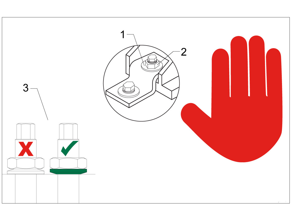
Note: The washers [1] and nuts [2] are installed during shipping and should be saved for installation and not be discarded.

Note: The washer orientation [3] is important.  The conical part of the washer should be against the casting,  see illustration.

Leveling Overview

Wiring connections to power the machine must be made before the Levelling Procedure can be followed. It is required that the machine be anchored in place for best and most consistent results while in use. The anchoring bolts (in accordance with the anchoring instructions) should be installed prior to the machine being set in place.

The installation process will be further aided if, when each base assembly is set in place, a very rough leveling procedure be done. The theoretical distance from the floor to the bottom of the two bases is 4 inches. The use of a machinist scale or small gauge blocks will expedite the process. While all leveling screws and leveling pads are in place measure from the floor to the bottom of each base until the distance is very close to the 4 inch height. This will accomplish two things: First, that the machine is set to the proper height to receive the coolant tank/Conveyor and, second, that the machine will be very much closer to level than without having done this procedure.

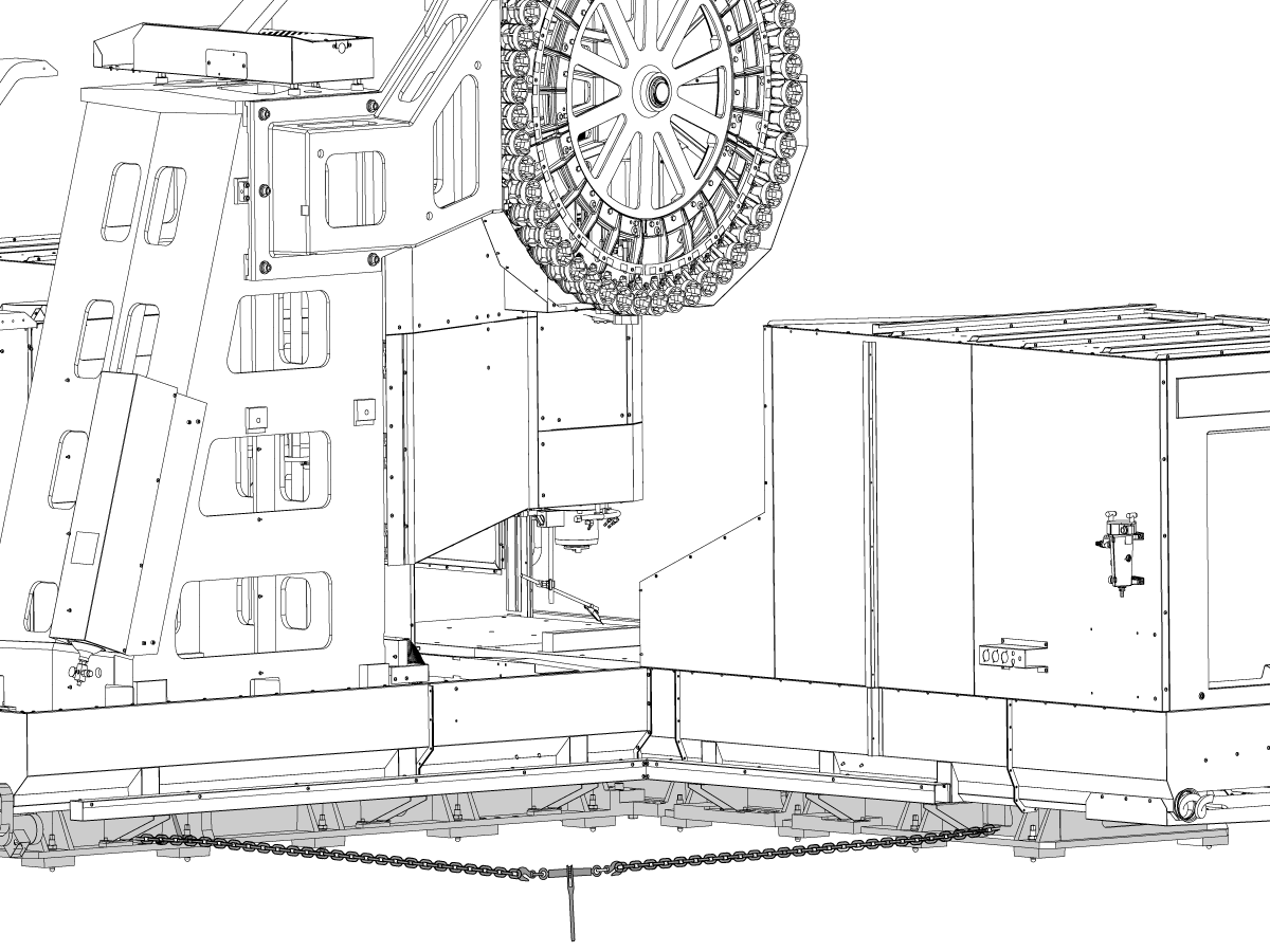
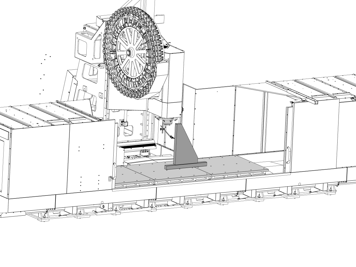
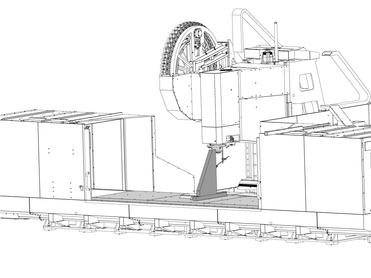
The installation procedure will necessarily follow the general outline below (a more detailed explanation follows). Depending on the available space and equipment it may be simpler to place the column base assembly before the table base assembly.  Regardless of which assembly is placed first, the concepts of the general outline need to be adhered to:

  • Remove the column base assembly from the truck
  • Stone and clean the table base mating flange
  • Remove the table base assembly from the truck and set 6" away from the column
  • Stone and clean the column base mating flange
  • Move the table base to mate with the column base
  • Be certain that all connecting bolts are in place but not tightened
  • Run the Pendant electrical wires over the top of the table enclosure and connect them in Operator pendent
  • Rough level the column base assembly
  • Remove the side panel from under the tool changer assembly
  • Install the counterbalance cylinder and charge the system
  • Relocate the tool changer ** (See Note Below)
  • Remove shipping blocks from the table base assembly 
  • Connect all air/electrical/oil lines between the two assemblies
  • Remove shipping blocks from the column base assembly
  • Power up the control
  • Fine level the column base assembly assembly
  • Fine level table base assembly/squaring the table base assembly to the column.
  • Fully tighten the connecting bolts and tighten anchors
  • Fully check machine geometry
  • Replace the side panel from under the tool changer assembly
  • Install the coolant supply system 
  • Check all motors for rotation/phasing

Note: (**)  Depending on the available space and equipment it may be simpler to relocate the tool changer assembly before moving the Column Base into the facility

Tool Changer Installation

1

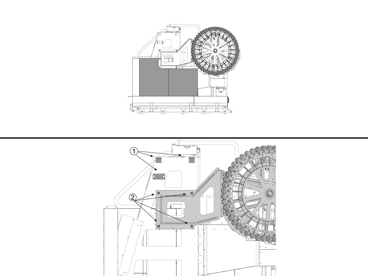
Important: Depending on the available space and equipment it may be simpler to relocate the tool changer assembly before moving the Column Base into the facility

Remove the side panels from under the tool changer.

Clean the mating surface for the tool changer [1].

Place a piece of cardboard between the spindle head and the tool changer to prevent scratching the spindle head covers.


2

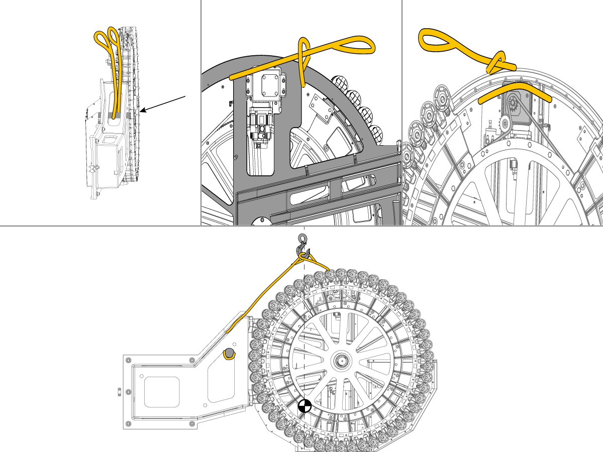
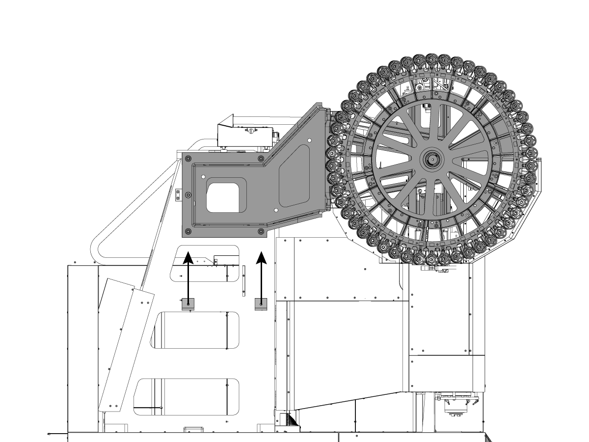
Note: Some components of the Carousel where removed for illustration purpose only.

Using the proper lifting equipment and lifting straps (2x) as shown to support the tool changer (aprox. 2670 lbs / 1211 kg).

Unbolt [2] the tool changer from the shipping location and lift it into position on the column and tighten the (6) bolts to 80 ft-lb (108 Nm).

Machine Placement

1

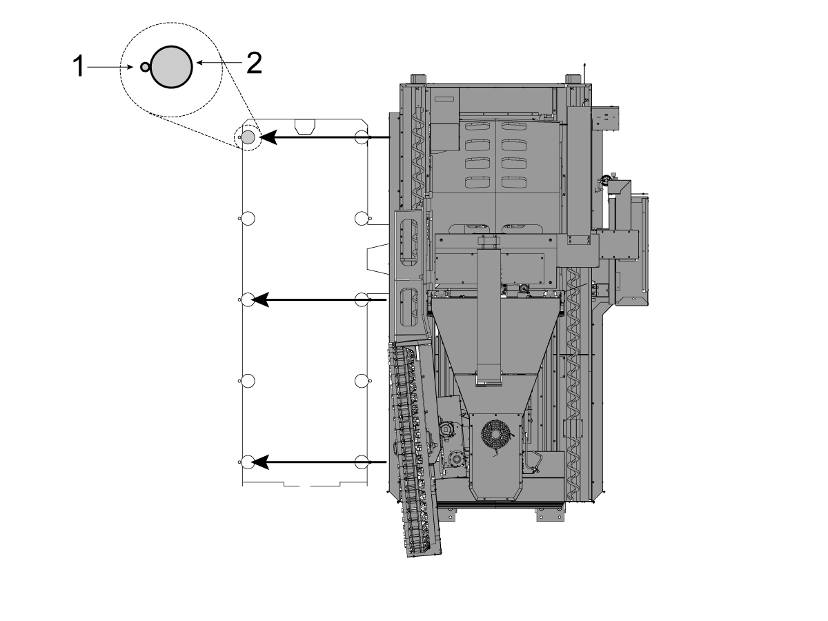
Important: Ensure the anchoring preparations are in accordance with the anchoring instructions prior to setting the machine in place. Image [1] Anchor hole [2] Leveling Pad

Place the column base assembly in position on the following leveling screws.

  • 1 - 2
  • 4 - 26
  • 6 - 24

Rough level by measuring from the floor to the bottom of the base 3". (4 - 4 1/2 inches for Conveyor Option). 

This will ensure that the final leveling procedure will go more quickly and that the coolant tank will properly fit beneath the coolant discharge. Loosely screw the jam nuts onto the leveling screws.

2

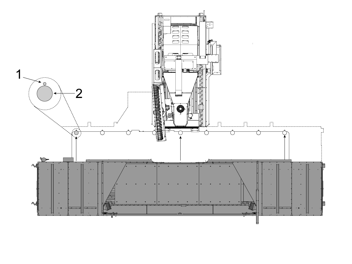
Place the table base assembly in position on the following leveling screws.. When placing the table base in position with respect to the column base, it is important that the two mating flanges be as parallel as possible (vertically and horizontally).

Rough level by measuring from the floor to the bottom of the base 3" (4 - 4 1/2 inches for Conveyor Option).  This will ensure that the final leveling procedure will go more quickly.

After rough leveling, verify that each of the screws are actually engaged in the threads, and that when the column base is in place and the mating surfaces are in contact that each.

3

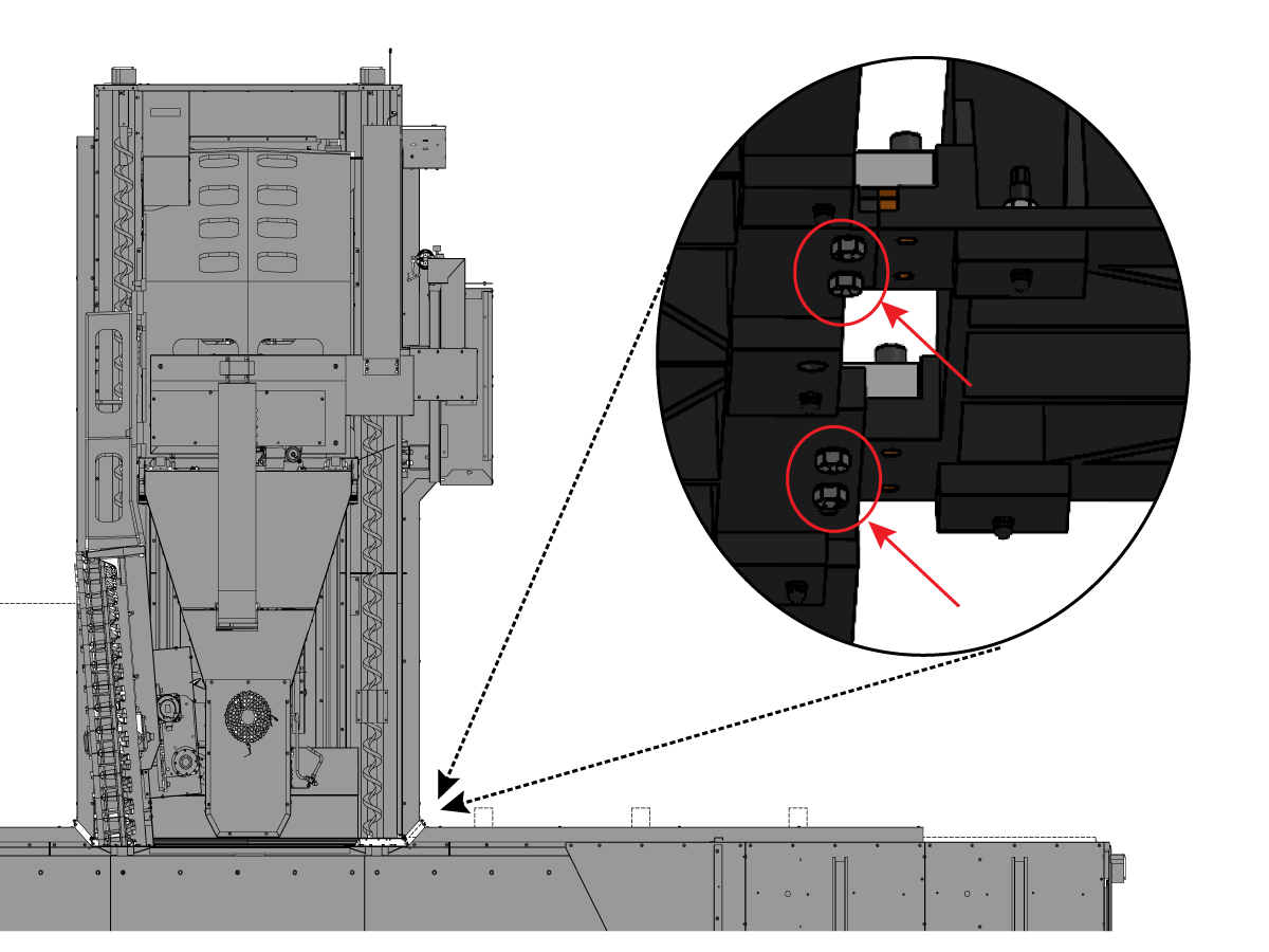
Be certain that the connecting screws are still free to rotate (do not leave the connecting bolts tight at this time because the machine still must be final leveled and squared)

INSTALL COUNTER BALANCE CYLINDER

1

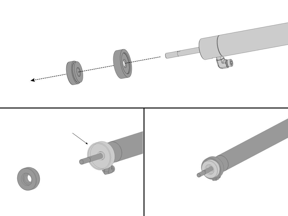
Note: The counterbalance cylinders have been removed (for overhead clearance during shipping), and they must be reinstalled and recharged with dry nitrogen prior to enabling the column axis

Re-install alignment collar and thrust bearing

  • Note orientation of alignment collar - deep shoulder faces rod end.

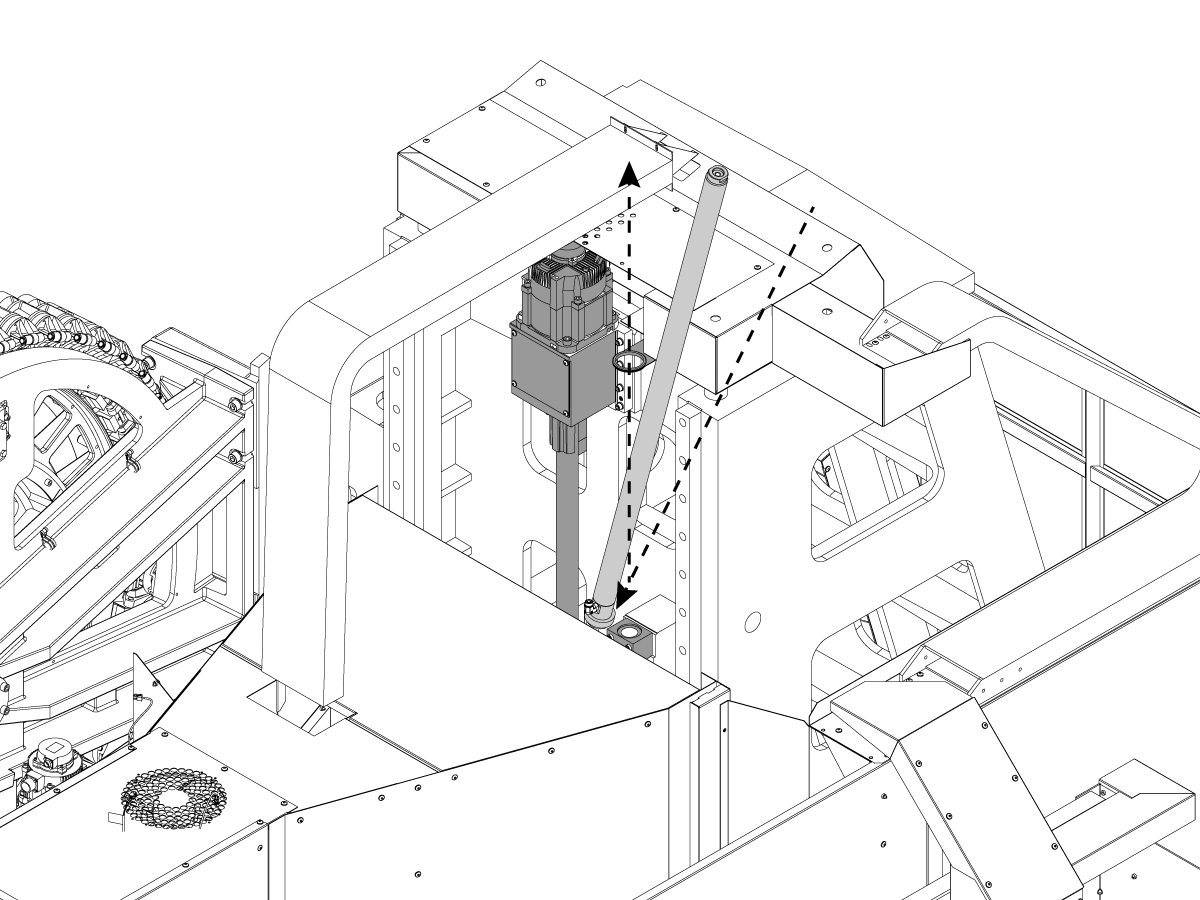
2

Insert the cylinder down between the spindle head casting and Column casting.

Slide the top of cylinder into the Rod Bracket until the bottom clears the Mount Block

Install cylinder assembly into mounting block on column 


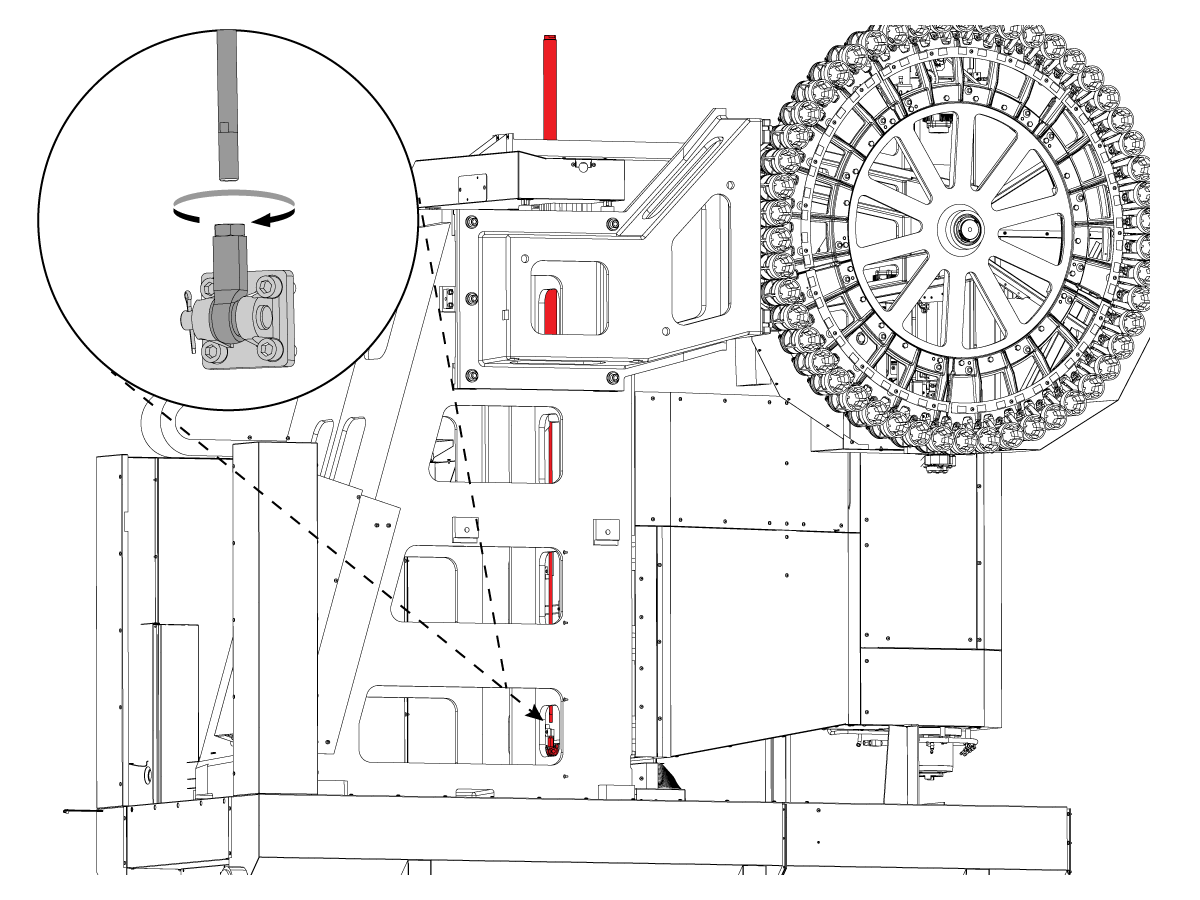
3

From the rear of the Column casting, extend cylinder rod and re- connect to the Rod End that is mounted on spindle head. 


4

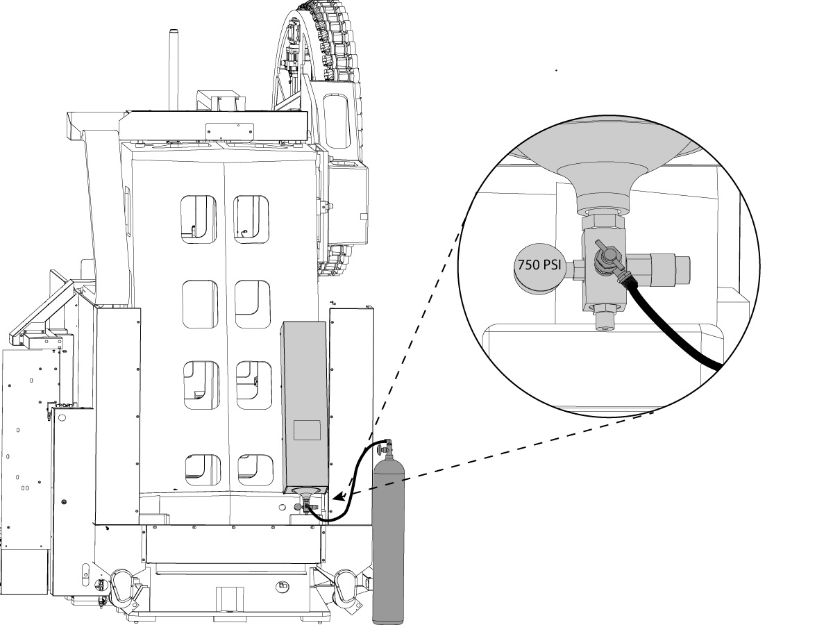
WARNING : Use appropriate PPE equipment (face shield, gloves, etc.) when filling the hydraulic tanks.

Make sure all tank valves are closed before beginning. 

Attach nitrogen tank fill nozzle

Begin filling counterbalance tank by SLOWLY cracking open the valve

Fill tank until gauge reads 750psi.

Wiring the Machine

1

Wiring the Column Base


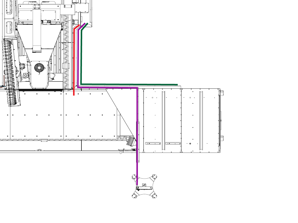
  • On the electrical cabinet side, Locate the bundle of wires (Purple Line) containing 
    • Right Door sensor cable
    • Air line (Right Door Interlock)
    • Right Side work light
    • RJ45 SHIELDED CABLE
    • USB 2.0 CABLE
    • CBL740/770/+12V&GND-SKBIF EXT VS
    • Work light
  • Route cable through the cable channel along the base of the Column and Table assembly.
  • Continue up the rear panel of the Table assembly and over the top of the enclosure in the cable channel.
  • Connect the work light cable into the splitter connector 
  • Insert the air into the right Door Interlock and connect the Right Door Sensor
  • From the Front Panel connect the RJ45 SHIELDED CABLE, USB 2.0 CABLE and CBL740/770/+12V&GND-SKBIF EXT VS 
  • route the Air Line into Front Panel and connect to the quick connect for the air nozzle.


2

Wiring the Column Base (Continue)
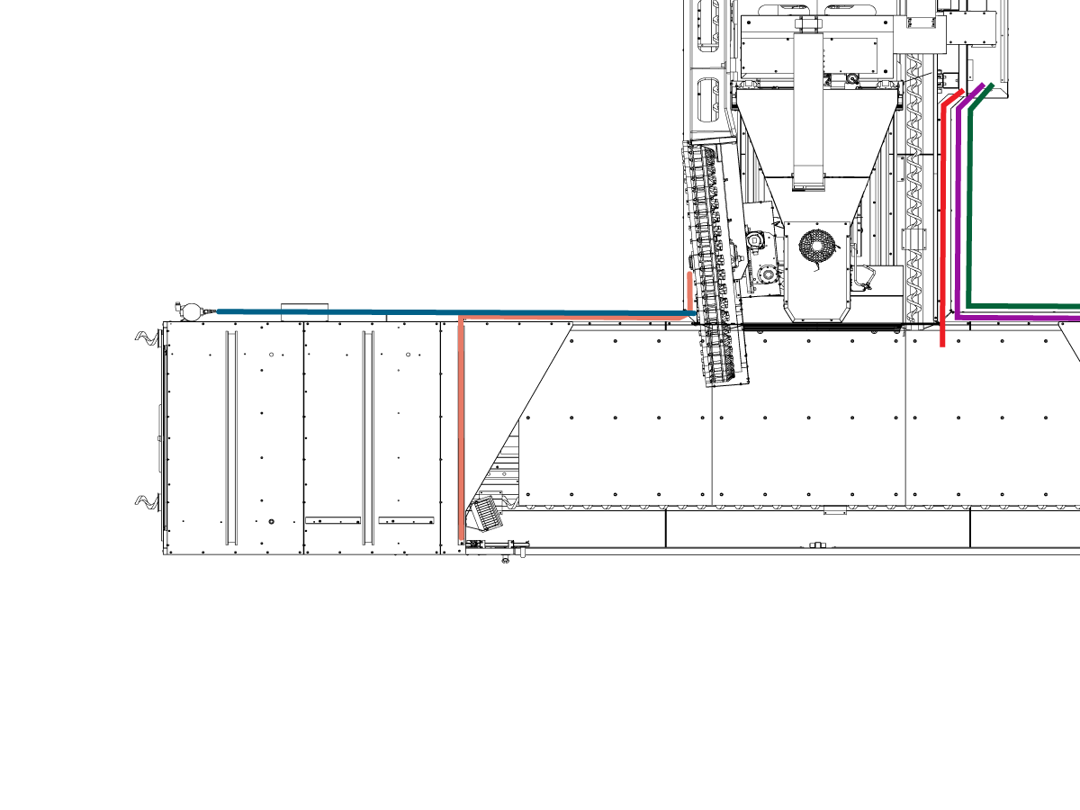
  • On the Tool Changer Side locate the bundle of wires containing
    • Coolant Electrical connection bracket (Blue Line)
    • Left Door Sensor cable (Orange Line)
    • Air Line (Left Door Interlock) (Orange Line)
    • Left side work light (Orange Line)
  • Route cable and coolant lines through the cable channel along the base of the Column and Table assembly.
  • Split the Door and work light cable from the coolant lines, continue routing the door and work light cables up the rear panel of the Table assembly and over the top of the enclosure in the cable channel.
  • Connect the work light cable into the splitter connector 
  • Insert the air into the Left Door Interlock and connect the Left Door Sensor
  • Continue routing the Coolant Line through the cable channel and mount the coolant electrical connection bracket to the back of the enclosure panel

3

Wiring the Table Base

  • On the Table Base locate the bundle of cable (Red Line) containing 
    • X - axis motor / encoder cable
    • X - axis Linear Scale cable
    • X - axis lube lines (2x)
  • Route the cables through the cable channel located on the side of the Column base and into the bottom control wire box.
  • In the wire box find the X-axis linear scale interpolation box and connect the X axis linear scale cable
  • Route the X-axis motor / encoder cable up into the Electrical Cabinet 
  • Connect the X axis motor cable the Amplifier and route the X axis encoder cable up to the Main Processor (P1)
  • Locate the Chip Auger motor cable (Green line) in the cable channel  and route to the electrical cabinet. 
  • Connect auger motors to open locaion on QUAD CHIPC  PBC  (P4 - P7)

Removal of Rust Inhibitor

For ease of removal, first use a plastic scraper to remove most of the rust inhibitor and then use WD-40 or another PH neutral degreaser to spray all the way covers and other non-painted surfaces that have been coated with rust inhibitor. Let it soak for a few minutes before removing it. Then use shop towels to remove it. For thick applications of rust inhibitor use a plastic scraper to remove it.

: https://vimeo.com/haasautomation/review/171129636/7c2a5127f9

 Important: Do not use scotch-brite or metal scrapers, these will scratch the way covers. Furthermore, to avoid any contamination of the way cover seals with the sticky residue. Do not move any of the axes until all the rust inhibitor has been removed.

Electrical Connections

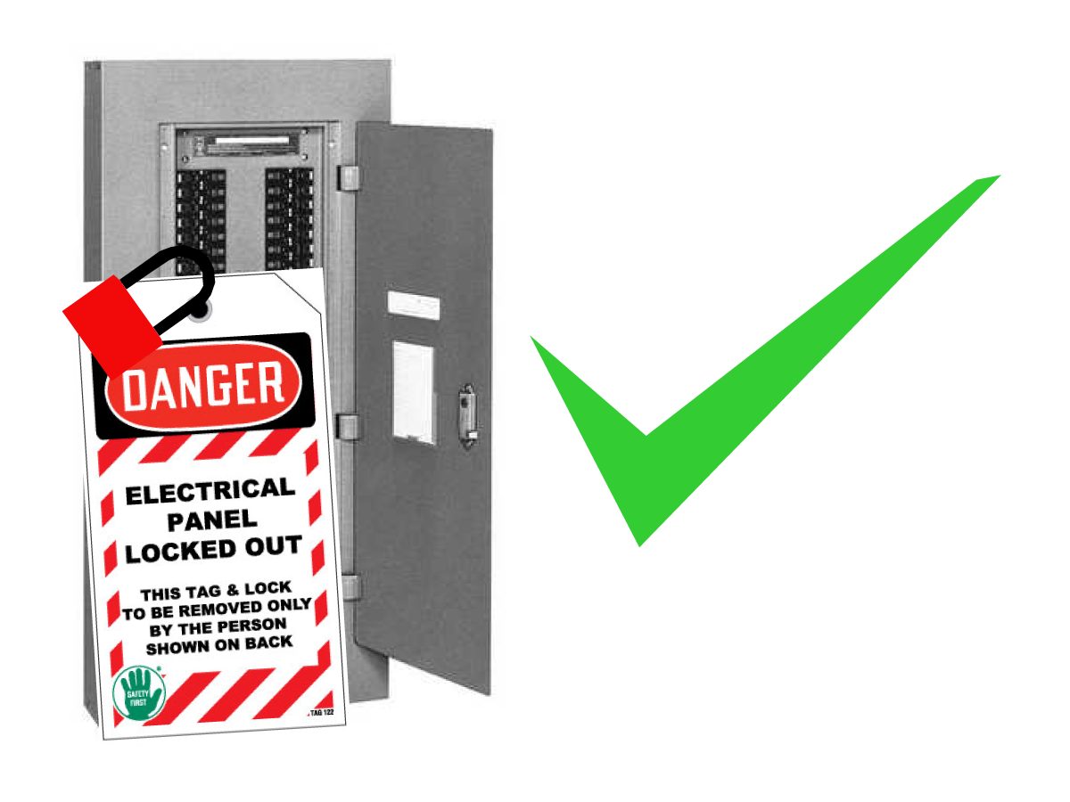
Danger: WORKING WITH ELECTRICAL SERVICES REQUIRED FOR A CNC ARE EXTREMELY HAZARDOUS. ALL POWER TO CNC MUST BE TURNED OFF LOCKOUT-TAGOUT AT THE SOURCE PRIOR TO CONNECTING THE LINE WIRES TO CNC. HOWEVER, IF THIS NOT THE CASE OR ARE NOT SURE HOW TO DO THIS, CHECK WITH APPROPIATE PERSONNEL OR OBTAIN THE NECESSARY HELP BEFORE CONTINUING. ALWAYS CHECK THE INCOMING LINES WITH AN AC VOLTAGE DETECTOR TO MAKE SURE POWER HAS BEEN DISCONNECTED.

1

Initial Control Inspection

Danger: At this point, there should be no electrical connection to the machine. Electrical panel must be closed and secured. When main switch is on, there is HIGH VOLTAGE throughout the electrical panel (including the circuit boards and logic circuits) and some components operate at high temperatures. Therefore, exercise extreme caution when working in the panel.

  • Set the main breaker switch at the upper right of the electrical panel on the back of the machine to OFF.
  • Using a screwdriver, unlock the two latches on the panel door, unlock the cabinet with the key and open the door.
  • Take sufficient time to check all the components and connectors associated with the circuit boards. Look for any cables that have become disconnected, look for any signs damage and loose parts in the bottom of the panel box. If there are any signs that the machine was mishandled, call the factory before proceeding.

2

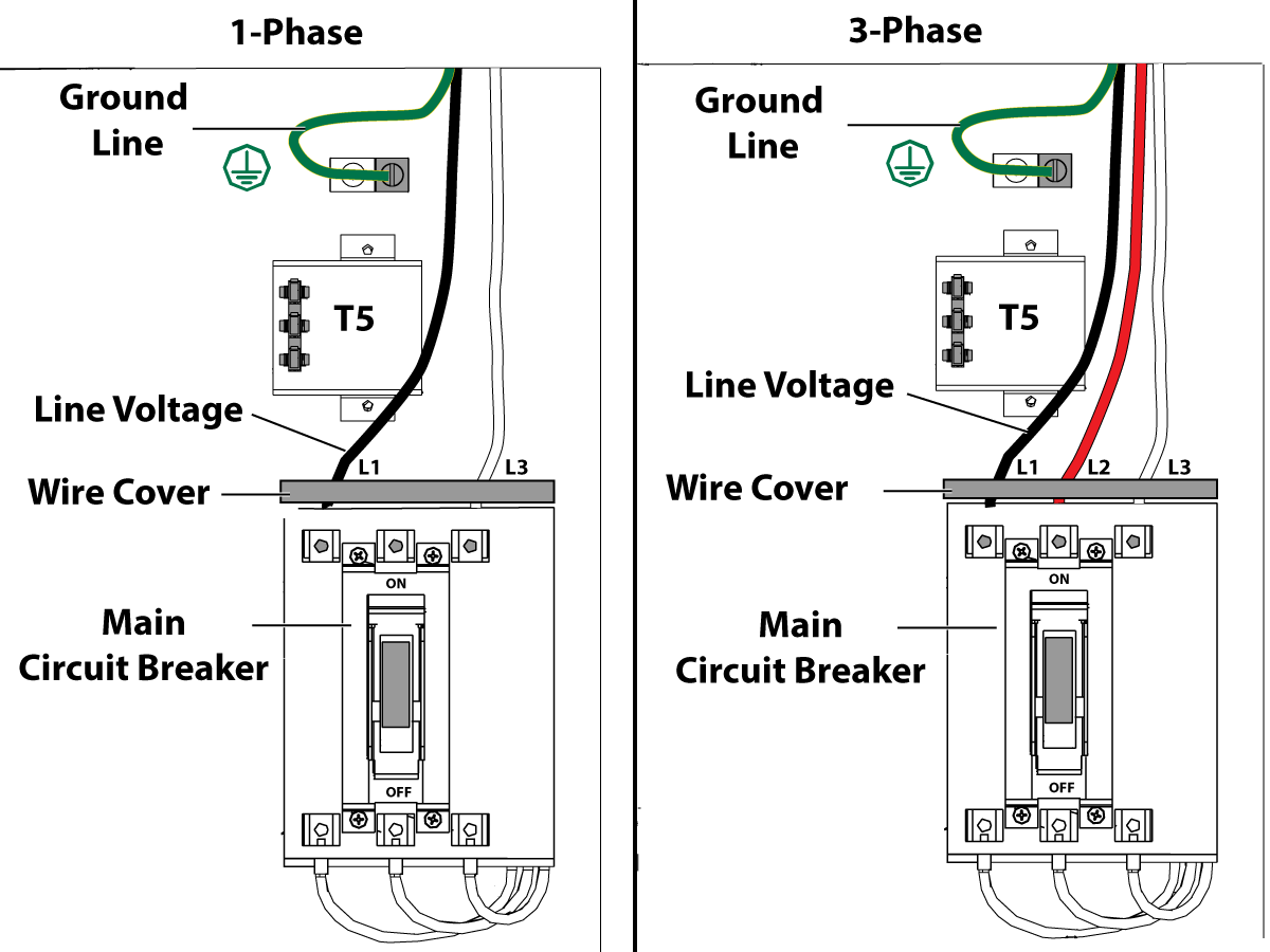
1-Phase Machines: Insert each power lead into the wire cover.  Connect the two power leads to L1 and L3 terminals on top of the main circuit breaker.

3-Phase Machines: Insert each power lead into the wire cover.  Connect the three power leads to L1, L2 and L3 terminals on top of the main circuit breaker.

Connect the separate ground line to the ground bus to the left of the terminals.

Refer to Haas Main CIrcuit Breaker - Torque Specifications for what value to torque the circuit breaker power leads.

 Note: Make sure that the leads actually go into the terminal-block clamps . (A poor connection will cause the machine to run intermittently or have other problems, such as servo overloads.) To check, simply pull on the wires after the screws are tightened.

3

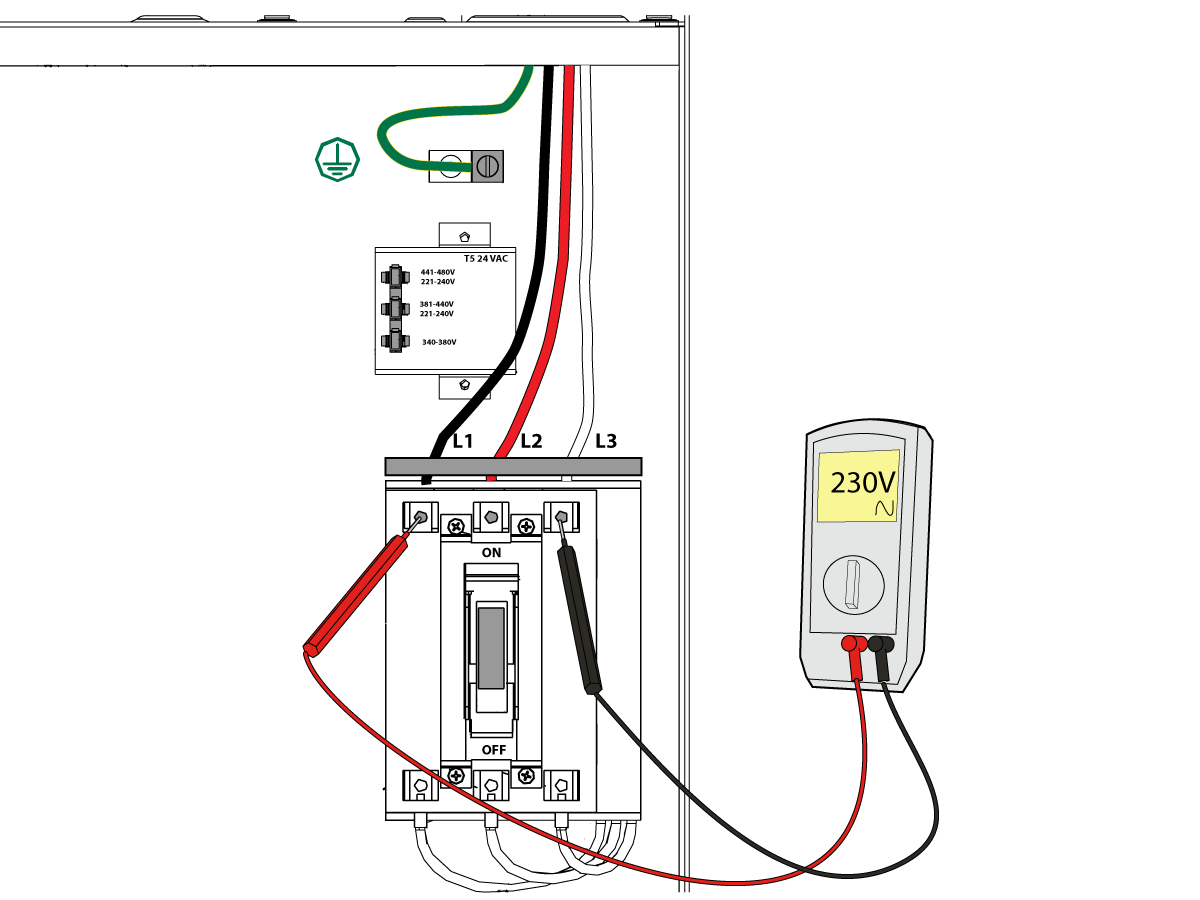
After the line voltage is connected to the machine, make sure that main circuit breaker (at top-right of rear cabinet) is OFF . Remove the Lockout / Tagout and Turn ON the power at the source. Using a digital voltmeter and appropriate safety procedures: 

1-Phase Machines: Measure the AC voltage across L1 & L3 at the main circuit breaker.  The AC voltage must be between 220 - 250 volts .
Note: Lower or higher than this voltage can generate low/high voltage alarms.

3-Phase Machines: Measure the AC voltage between all three pair phases at the main circuit breaker.  The AC voltage must be between 195 and 260 volts (360 and 480 volts for high voltage option).

 Note: Wide voltage fluctuations are common in many industrial areas; minimum and maximum voltage supplied to a machine while it is in operation must be known. U.S. National Electrical Code specifies that machines should operate with a variation of +5% to -5% around an average supply voltage. If problems with line voltage occur, or low line voltage is suspected, an external transformer may be used. If you suspect voltage problems, voltage should be checked every hour or two during a typical day to be sure it does not fluctuate more than +5% or -5% from an average.

4

Important: With the main circuit breaker turned OFF.

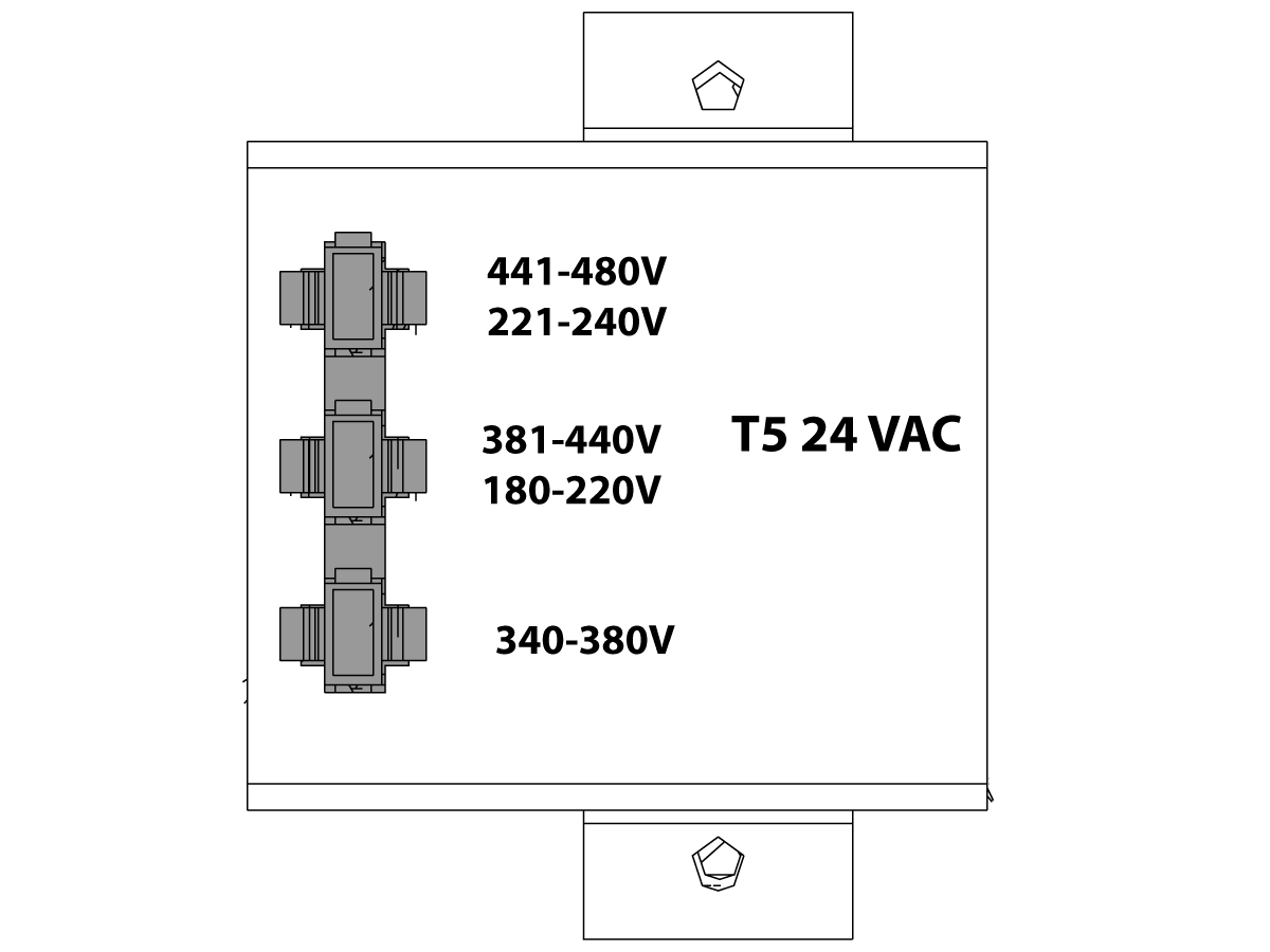
Check the transformer taps at the bottom-right corner of the rear cabinet.

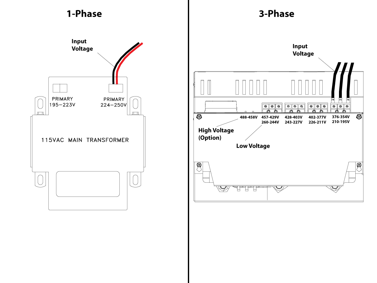
1-Phase Machines: The input voltage cable must be moved to the connector which corresponds to the average voltage measured in the above step.

3-Phase Machines:  The input voltage cables labeled 74, 75, and 76 must be moved to the terminal block triple which corresponds to the average voltage measured in the above step.

5

Transformer T5 supplies 24VAC used to power the main contactor. There are two versions of this transformer for use on a 240 and 400V machines. The 240V transformer has two input connectors located about two inches from the transformer, which allow it to be connected to either 180-220V or 221-240V. Users that have 220V-240V RMS input power should use the connector labeled 221-240V, while users with 190-220V input power should use the connector labeled 180-220V. Failure to use the correct input connector will result in either overheating of the main contactor or failure to reliably engage the main contactor.

The 480V (option) T5 transformer has three input connectors, labeled 340-380V, 381-440V and 441-480V. Users with 340-380V 50Hz power should use the 340-380V connector while users with 380V-440V 50Hz power should use the 381-440V connector.

Important: Set the main circuit breaker to ON. Check for evidence of problems, such as the smell of overheating components or smoke. If such problems are indicated, immediately set the main circuit breaker to OFF and call the factory before proceeding.

After the power is on, measure the voltage across the bottom terminals on the main circuit breaker. It should be the same as the measurements where the input power connects to the main breaker. If there are any problems, check the wiring.

6

Apply power to the control by pressing the Power-On switch on the front panel.

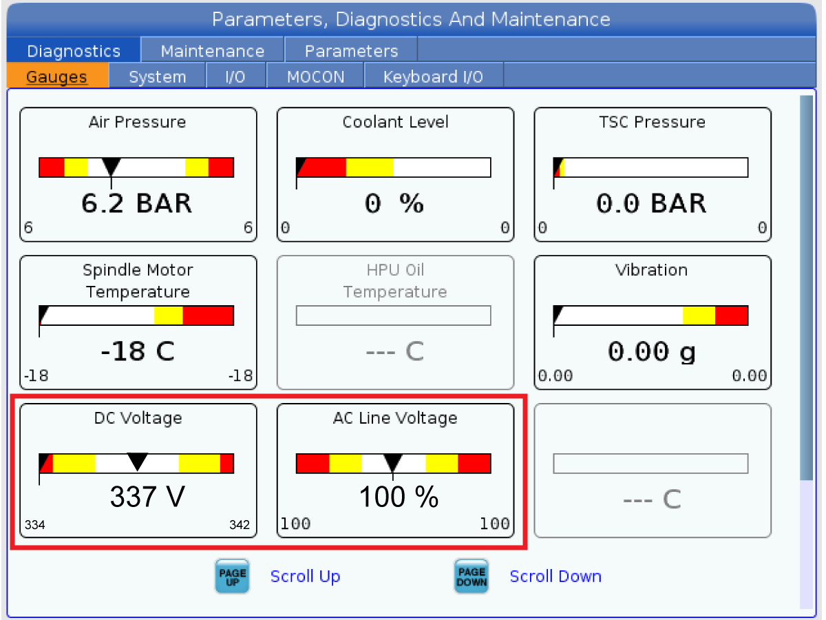
Check the DC Voltage and AC Line Voltage gauges in Diagnostics. The DC Voltage gauge must read between 310 - 360V. The AC Line Voltage must be between 90 and 105 percent. If the voltage is outside these limits, turn off the power and recheck steps 2 and 3. If the voltage is still outside these limits, call the factory.

7

Electrical power must be phased properly to avoid damage to your equipment. The Power Supply Assembly PC board incorporates a "Phase Detect" circuit with neon indicators. When the orange neon is lit (NE5), the phasing is incorrect. If the green neon is lit (NE6), the phasing is correct. If both neon indicators are lit, you have a loose wire; check the connections. Adjust phasing by setting the source power to off and then swapping L1 and L2 of the incoming power lines at the main circuit breaker.

Danger: ALL POWER TO CNC MUST BE TURNED OFF LOCKOUT-TAGOUT AT THE SOURCE PRIOR TO ADJUSTING PHASING. ALWAYS DOUBLE CHECK THE INCOMING LINES WITH AN AC VOLTAGE DETECTOR.

Turn off the power and set the main circuit breaker to OFF. Close the door, lock the latches, and turn the power back on.

Remove the key from the control cabinet and give it to the shop manager.

8

Activation

When the machine is properly placed and connected to both air and electrical power, it is ready for final installation (removing shipping blocks, leveling, spindle sweep, etc.) and software activation. The HFO service technician does this. Contact the local HFO to schedule the work.

Unblocking the Machine

1

Unblocking the Column Base


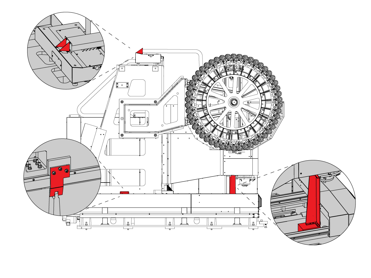
CAUTION: Before unblocking machine ensure that counterbalance cylinder charging hose is attached to nitrogen tank and nitrogen tank is fully charged to 750 psi.

  • Remove the shipping bracket and hardware completely from the side of column base on the Tool Changer side.
  • Handle jog (without zero return) the spindle head to the up position and support the bellows.
  • Remove the spindle shipping bracket 

2

Unblocking the Table Base

  • Remove the shipping bracket and hardware completely from the front of Table base 

Machine Leveling

Leveling the Machine

At this point the machine is completely unblocked and all axes are enabled. The process of leveling can now begin. The following criteria should have already been met at this point:

  • The machine correctly placed with respect to the anchoring points.
  • The rough leveling has taken place, ensuring that the bottom of the two bases are very close to 4 inches off the floor
  • The mating flanges of the two bases have been pulled into contact.
  • The screws that connect the two bases have been backed off and can rotate freely

1

Rough leveling the Column Base


  • Zero return all axes 3.
  • Move the Y-axis to the center of travel. 
  • With four leveling screws on the corners on the column base.
    • 1 - 2
    • 6 - 24
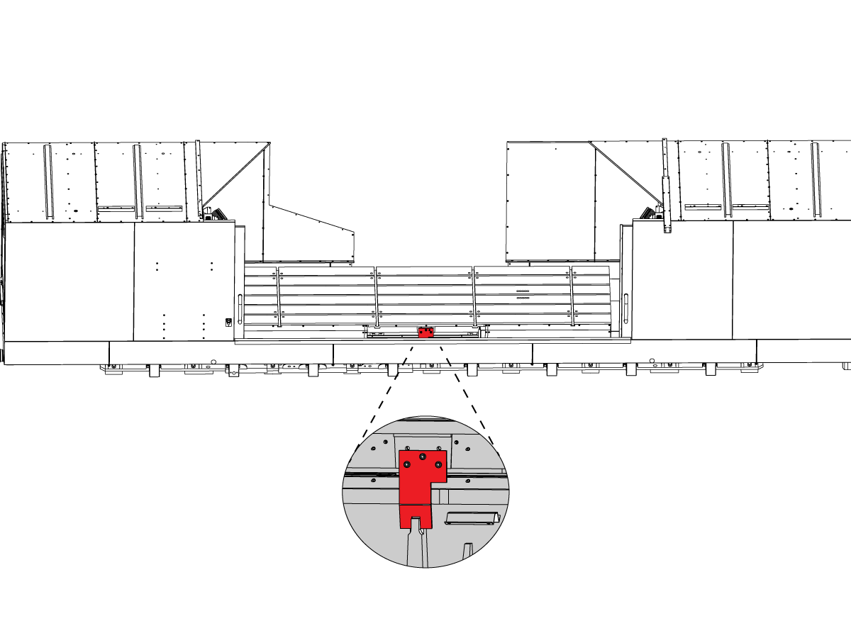
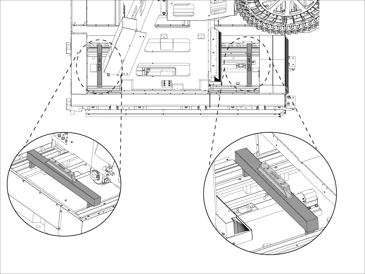
  • With the column at approximately center of travel, using gauge blocks lay one granite parallel across the linear guides as close to the table as possible and another granite parallel across the linear guides as near the rear of the machine as possible.
  • Place a level on each parallel and adjust the level of the column from side to side.
  • Check the freedom of the mating flange screws to be certain there is no binding.
  • On the guide nearest the control, place one level on the linear guide in front of the column and one level on the linear guide to the rear of the column. Adjust the level of the machine in the direction of Y-axis travel. Move the levels to the opposite linear guide and complete the process.
  • When the column base is level to earth in both directions, the six center leveling screws should be lowered to touch the leveling pads.
  • Remove the granite parallels from the column base.

2

Level of the Column Base

  • Handle jog the column to the rear.
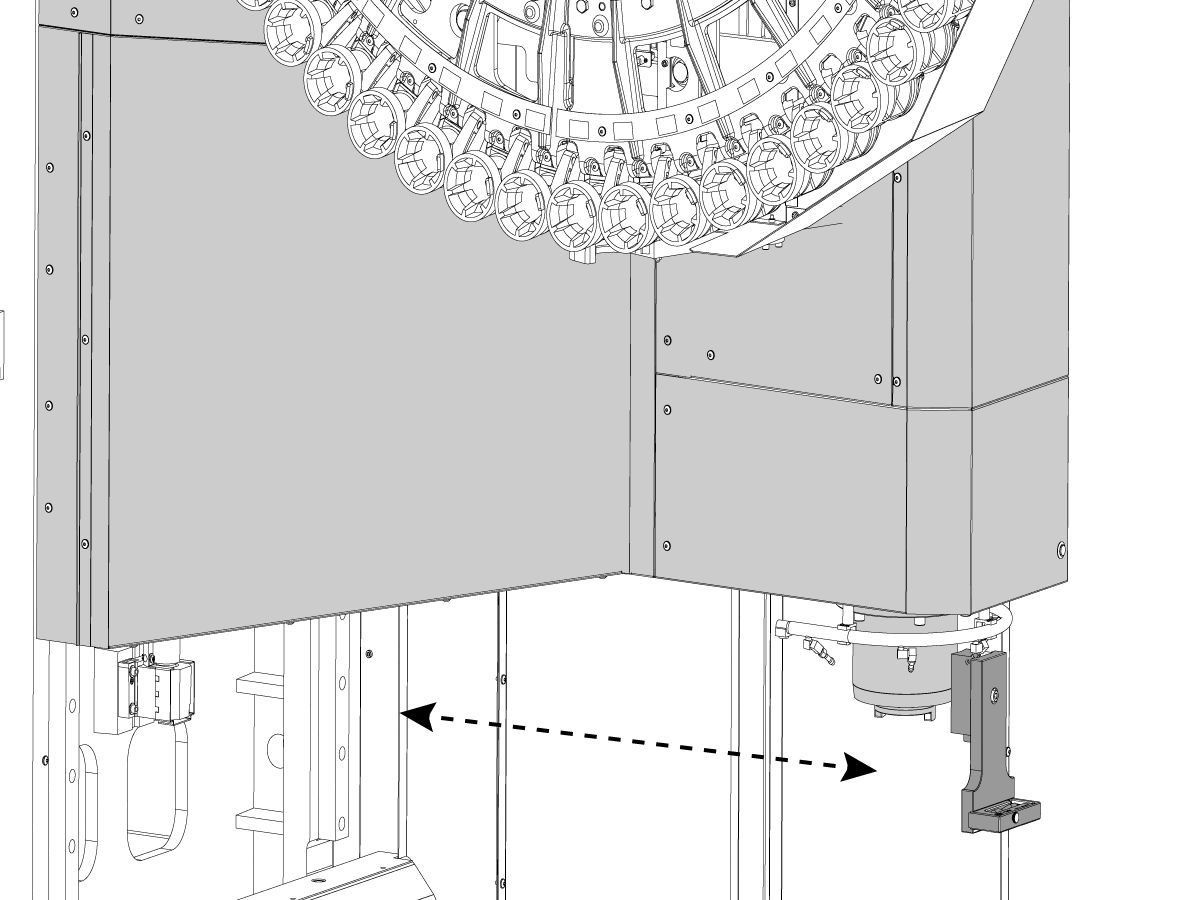
  • Place a single level (T-2181 and T-2192) on the spindle, parallel to the X-axis of the machine. It is very unlikely that this surface will read zero; do not expect it to. Make note of the reading that is present.
  • While monitoring the level, move the column all the way forward and check if there is a change in the level reading. If there is no change in reading, then the column base has no twist. If there is a twist in the base, this must be corrected by using leveling feet 1,2,4 and 26.

3


Rough leveling the Table Base


  • Move the X-axis to the center of travel.
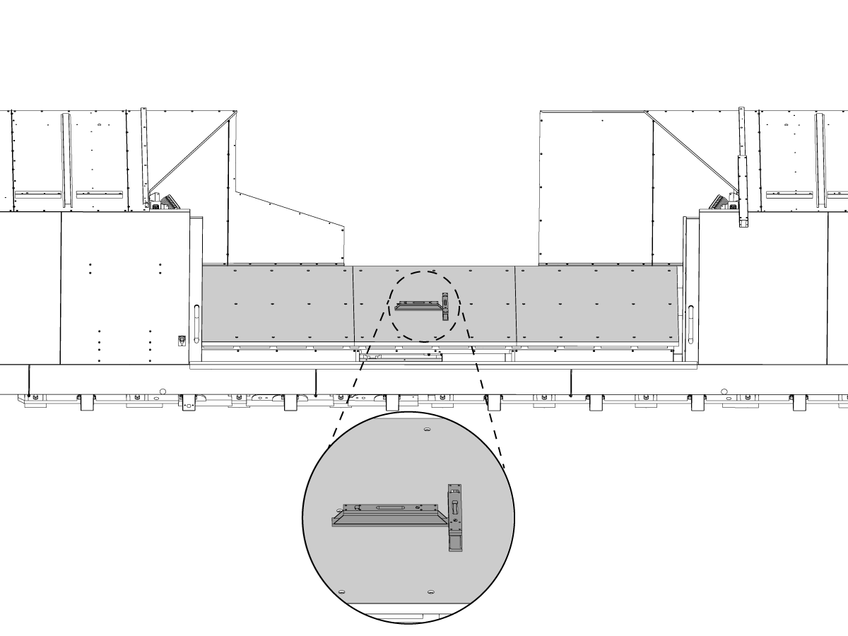
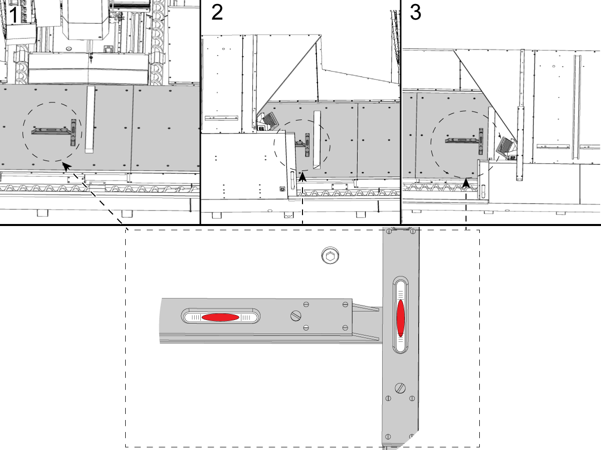
  •  Place two levels at right angles to each other as close as possible to the center of the table. One will show the level across the width of the table and the other will show the level along the length of the table.
  • Focus on leveling the table only in this X-axis position to establish a primary datum for the machine. Adjust only the four leveling screws: 7, 14, 16 and 23. 
  • When the table level is close to zero in both directions, the four very end leveling screws (10, 11, 19 and 20) may be brought down to touch the leveling pads.
  •  Continue to level the table base until both levels on the table read zero.

4

Sweeping the Table

  • Mounting the indicator on the spindle, first verify that the table is flat to the Y-axis plane.
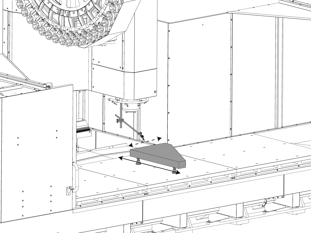
  • Place a parallel granite (32") on the table surface. Sweep the granite in the Y-axis to determine, and correct column / table flatness in the Y-axis direction. This is a very sensitive measurement method and corrections to this flatness should be made in conservative steps.
  • Raise or lower the front of the table to get the flatness within specification using leveling screws 14 and 16.
  • Move the levels to the table and place them as close to the center as possible.
  • One level should be parallel to the X-axis and one level should be perpendicular to the X-axis.
  • Once the Column to Table flatness has been established, jog the X-axis and adjust the remaining leveling screws to maintain the current level reading.

5


level the Table 


  • Focus on leveling the table only in this X-axis plane to establish a primary datum from the granite. 
  • Make note of the reading that is present. 
  • While monitoring the level, jog the table all the way to left and check if there is a change in the level reading.
  • While monitoring the level, jog the table all the way to right and check if there is a change in the level reading.
  •  If there is no change of reading, then the column base has no twist. If there is a twist in the table, this must be corrected.
  •  the remaining leveling screws should be lowered to touch the leveling pads.

Geometry Check

1

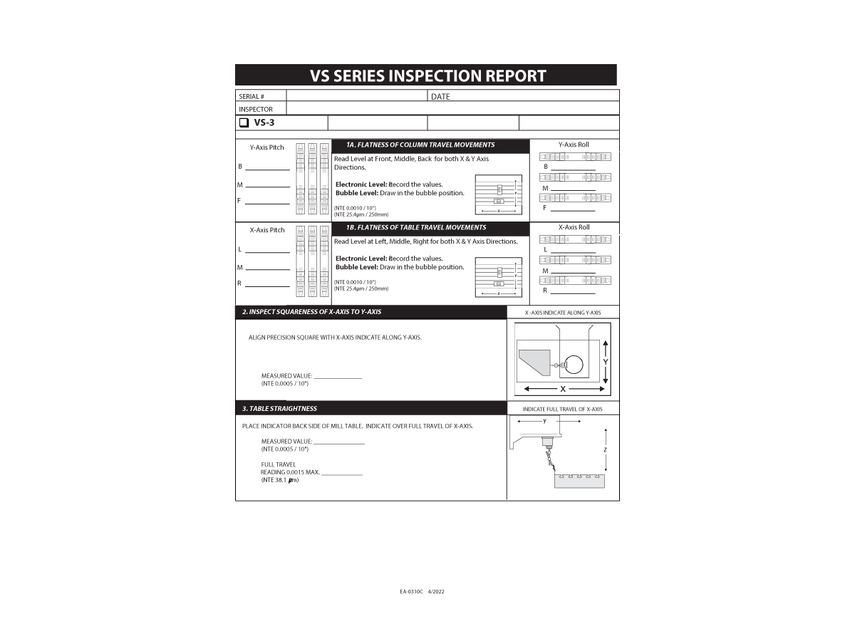
Every point of inspection must be verified to be within the tolerances specified for the machine. 

  • 1A. FLATNESS OF COLUMN TRAVEL MOVEMENTS
  • 1B. FLATNESS OF TABLE TRAVEL MOVEMENTS
  • 2. INSPECT SQUARENESS OF X-AXIS TO Y-AXIS
  • 3. TABLE STRAIGHTNESS
  • 4A. SQUARENESS OF Z-AXIS MOTION TO X-AXIS
  • 4B. SQUARENESS O F Z-AXIS MOTION TO Y AXIS
  • 5. SPINDLE SWEEP
  • 6A. SPINDLE RUNOUT AT TAPER
  • 6B. SPINDLE RUNOUT ON TEST TOOL BAR
  • 7. PARALLELISM OF TABLE TO X - Y MOTION

2

Two fundamental geometry checks need to be made. The first is the perpendicularity of the X-axis to the Y-axis, and the second is to verify the sweep of the Z-axis.

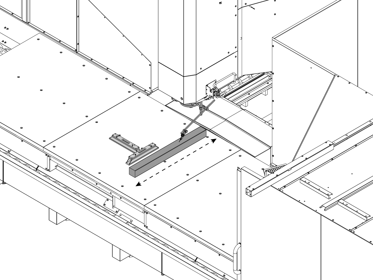
  • The sweep of the X-axis to the Y-axis is accomplished using a granite square. Set zero by sweeping the Y-axis on one side of the square, and then to verify that the motion of the X-axis is perpendicular by sweeping the adjacent side of the square. If the X-axis and Y-axis are not found to be within tolerance, between the mating flange surfaces that is creating this error.

Observe readings and adjust base to saddle perpendicularity as follows:

  • Route ratchet straps from both sides of base to ends of saddle, looping through casting holes.
  • Remove slack from both straps without over tightening.
  • Gently tighten the appropriate strap observing reading changes on indicator.
  • Continue making slight adjustments with straps and repeat granite sweeps until perpendicularity reading is within traveler specifications - record readings.

3

Verify the sweep of the Y/Z-axis:

  • Sweeping the Z-axis is accomplished using a cylinder square. 
  • The line of motion of the Z-axis will be checked by comparing it to the line of intersection of the two most convenient relative planes, that of the X-Z plane and the Y-Z plane.
  •  By assuring that each of these planes are perpendicular to the X-Y plane within specification, the machine geometry will be preserved. 

Observe readings and adjust the needed Column Base leveling screws:


  • X-Z plane: 
    • Adjust the left / right leveling screw evenly up or down to bring the reading within specification.
  • Y-Z plane:
    • Adjust the rear leveling screw evenly up or down to bring the reading within specification.

Final Connection of the Column Base to the Table Base

  • Before tightening all the connecting screws, recheck the table level to be certain that the squaring process of the column base did not affect table level.
  • Torque the connecting screws with lock washers in place to 400 ft-lb. 


Anchoring the Machine in Place

NOTE: Ensure the anchoring preparations are in accordance with the anchoring instructions prior to setting the machine in place


1

  • Complete the machine installation, install the anchor bolts and tightening to 25 ft-lb. 
  • Repeat of the basic leveling procedure and a recheck of the geometry to be done. All criteria must be met.


Completing the Installation

1

  1.  Seal the shipping bracket bolt holes to prevent oil leaks.
  2.  Replace all sheet metal removed paying particular attention to sealing any component mating surface potentially exposed to coolant flow.
  3. Verify alignment and operation of the tool changer.
  • Using a split tool in RECOVERY mode, verify the alignment to the pocket and check the alignment to the spindle.
  • With the (4) TC bolts loose support the weight of the tool changer, use the jacking screws for the SMTC adjuster to align the front-to-back of the arm to the spindle. The tool changer will not move unless you support the weight.
  • If the spindle alignment is out side-to-side, insert a shim between the tool changer and the mount. Do not leave the shim exposed

4. Verify all machine functions.

BUSCAR DISTRIBUIDOR
Comentarios
Haas Logo

美元价格不包括关税、报关费用、保险费、增值税及运费。
USD prices DO NOT include customs duty, customs fees, insurance, VAT, or freight.

人民币价格包含关税、报关费用、货运保险和增值税, 但不包括运费。
CNY prices include customs duty, customs fees, insurance, and VAT. DOES NOT include freight.

Precio entregado por Haas

Este precio incluye el coste de envío, los aranceles de exportación e importación, el seguro y cualquier otro gasto en el que se incurra durante el envío a un lugar en Francia acordado con usted como comprador. No se pueden agregar otros costes obligatorios a la entrega de un producto CNC de Haas.

ESTÉ AL TANTO DE LO ÚLTIMO EN TECNOLOGÍA Y CONSEJOS DE HAAS...

¡Regístrese ya!   

HAAS TOOLING ACCEPTS THE FOLLOWING:
  • Servicio y asistencia
  • Propietarios
  • Solicitar mantenimiento
  • Manuales del operador
  • Recambios Haas
  • Solicitud de reparación de equipo rotativo
  • Guías de preinstalación
  • Comprar herramientas
  • Configure y sepa el precio de su nueva máquina Haas
  • Inventario disponible
  • Lista de precios de Haas
  • Financiación CNCA
  • Acerca de Haas
  • Oportunidades laborales
  • Certificados y seguridad
  • Póngase en contacto
  • Historial
  • CONDICIONES
  • Términos y condiciones de Haas Tooling
  • Privacidad
  • Garantía
  • Comunidad Haas
  • Programa de certificación de Haas
  • Haas Motorsports
  • Fundación Gene Haas
  • Comunidad de formación técnica de Haas
  • Eventos
  • Participe en la conversación
  • Facebook
  • Twitter
  • Flickr
  • YouTube
  • LinkedIn
  • Instagram
  • TikTok
© 2023 Haas Automation, Inc - Máquinas herramienta CNC

This site is protected by reCAPTCHA and the Google Privacy Policy y Terms of Service apply.


2800 Sturgis Rd., Oxnard, CA 93030 / Toll Free: 800-331-6746
Phone: 805-278-1800 / Fax: 805-278-2255

Aviso sobre cookies

Utilizamos cookies para mejorar su experiencia de usuario. Nuestro aviso de cookies describe las cookies que utilizamos, por qué las utilizamos y cómo puede encontrar más información al respecto. Confirme que acepta que utilicemos las cookies de análisis. Si no acepta, puede seguir utilizando nuestro sitio web con una experiencia de usuario reducida.

Administrar ajustes

Aviso sobre cookies

Utilizamos cookies para mejorar su experiencia de usuario. Nuestro aviso de cookies describe las cookies que utilizamos, por qué las utilizamos y cómo puede encontrar más información al respecto. Confirme que acepta que utilicemos las cookies de análisis. Si no acepta, puede seguir utilizando nuestro sitio web con una experiencia de usuario reducida.

Functional Cookies

Analytics Cookies