My Haas Tervetuloa,
!
Haas Tooling MyHaas/HaasConnect Kirjaudu sisään Rekisteröinti Haas Tooling MyHaas/HaasConnect Kirjaudu ulos Tervetuloa, Omat koneeni Viimeisin toiminta Omat tarjoukseni Oma tilini Omat käyttäjäni Kirjaudu ulos
Etsi jälleenmyyjä
  1. Valitse kieli
    1. English
    2. Deutsch
    3. Español - ES
    4. Español - MX
    5. Français
    6. Italiano
    7. Português
    8. Český
    9. Dansk
    10. Nederlands
    11. Magyar
    12. Polski
    13. Svenska
    14. Türkçe
    15. 中文
    16. Suomi
    17. Norsk
    18. الإنجليزية
    19. български
    20. Hrvatski
    21. Ελληνικά
    22. Română
    23. Slovenský
    24. Slovenščina
    25. 한국어
    26. 日本語
    27. Українська
  • koneet Main Menu
    • Pystykaraiset jyrsinkoneet
      Pystykaraiset jyrsinkoneet
      Pystykaraiset jyrsinkoneet View All
      • Pystykaraiset jyrsinkoneet
      • VF-sarja
      • Yleiskoneet
      • VR-sarja
      • VP-5 Prismaattinen
      • Palettia vaihtavat pystykaraiset työstökeskukset
      • Mini Mills
      • Muottikoneet
      • Suurnopeusporauskeskukset
      • Poraus-/kierteitys-/jyrsintäsarja
      • Työkalujyrsinkoneet
      • Pocket Mill
      • Compact Mill -jyrsinkoneet
      • Portaalisarja
      • SR-levyreitittimet
      • Erittäin suuri pystytyöstökeskus
      • Kaksipylväiset jyrsinkoneet
    • Moniakseliset ratkaisut
      Moniakseliset ratkaisut
      Moniakseliset ratkaisut View All
      • Moniakseliset ratkaisut
      • Y-akselisorvit
      • 5-akseliset jyrsinkoneet
    • Sorvit
      Sorvit
      Sorvit View All
      • Sorvit
      • ST-sarja
      • Kaksikarainen
      • Kaavauskehysjohdesorvisarja
      • Työkalusorvit
      • Istukkasorvi
      • Taskusorvi
      • Haas tangonsyöttölaitteet
    • Vaakakaraiset jyrsinkoneet
      Vaakakaraiset jyrsinkoneet
      Vaakakaraiset jyrsinkoneet View All
      • Vaakakaraiset jyrsinkoneet
      • 50-kartioinen
      • 40-kartioiset
    • Pyöröpöydät ja paikoittimet
      Pyöröpöydät ja paikoittimet
      Pyöröpöydät ja paikoittimet View All
      • Pyöröpöydät ja paikoittimet
      • Pyöröpöydät
      • Paikoittimet
      • 5-akseliset pyöröpöydät
      • Erittäin suuret pyöröpöydät
    • Automaatiojärjestelmät
      Automaatiojärjestelmät
      Automaatiojärjestelmät View All
      • Automaatiojärjestelmät
      • Jyrsinkoneen automaatio
      • Sorvin automaatio
      • Automaattiset kappaleenlataajat
      • Automaatiomallit
    • Pöytäkoneet
      Pöytäkoneet
      Pöytäkoneet View All
      • Pöytäkoneet
      • Pöytäjyrsinkone
      • Pöytäsorvi
      • Ohjaussimulaattori, vakio
      • Ohjaussimulaattori, Premium
    • Osta laitteita
      Osta laitteita
      Osta laitteita View All
      • Osta laitteita
      • Jyrsinkone
      • Haasin käsikäyttöiset sorvit
      • Haas-sahat
    • Valmistuskoneet
      Valmistuskoneet
      Valmistuskoneet View All
      • Valmistuskoneet
      • Laserleikkauskoneet
      • CNC-särmäyspuristimet
    • PIKALINKIT Erikoissarjat  Erikoissarjat 
      EU-SARJA EU-SARJA RAKENNA JA MÄÄRITÄ HINTA | HINNASTO RAKENNA JA MÄÄRITÄ HINTA | HINNASTO Varastossa olevat koneet Varastossa olevat koneet MITÄ UUTTA MITÄ UUTTA YOUR FIRST CNC YOUR FIRST CNC
      TYÖKALUJA OSTAMISEEN
      • Haas-koneen kokoonpano ja hinta
      • Hintalista
      • Käytettävissä oleva varasto
      • CNCA-rahoitus
      HALUATKO KESKUSTELLA JONKUN KANSSA?

      Haas Factory Outlet (HFO) osaa vastata kysymyksiisi ja auttaa sinua parhaan vaihtoehdon valitsemisessa.

      CONTACT YOUR DISTRIBUTOR >
  • Valinnat Main Menu
    • The Haas Control Tuottavuuspaketit
      Tuottavuuspaketit
      Tuottavuuspaketit View All
      • Tuottavuuspaketit
    • Product Image Karat
      Karat
      Karat View All
      • Karat
    • Product Image Työkalunvaihtajat
      Työkalunvaihtajat
      Työkalunvaihtajat View All
      • Työkalunvaihtajat
    • Product Image 4- | 5-akselin valmius
      4- | 5-akselin valmius
      4- | 5-akselin valmius View All
      • 4- | 5-akselin valmius
    • Product Image Revolverit ja pyörivät työkalut
      Revolverit ja pyörivät työkalut
      Revolverit ja pyörivät työkalut View All
      • Revolverit ja pyörivät työkalut
    • Product Image Mittaus
      Mittaus
      Mittaus View All
      • Mittaus
    • Haasin lastujen ja jäähdytysnesteen hallinta Lastujen ja jäähdytysnesteen hallinta
      Lastujen ja jäähdytysnesteen hallinta
      Lastujen ja jäähdytysnesteen hallinta View All
      • Lastujen ja jäähdytysnesteen hallinta
    • Haas-ohjaus Haas-ohjaus
      Haas-ohjaus
      Haas-ohjaus View All
      • Haas-ohjaus
    • Product Image Tuotevaihtoehdot
      Tuotevaihtoehdot
      Tuotevaihtoehdot View All
      • Tuotevaihtoehdot
    • Product Image Työkalut ja kiinnittäminen
      Työkalut ja kiinnittäminen
      Työkalut ja kiinnittäminen View All
      • Työkalut ja kiinnittäminen
    • Product Image Työkappaleen kiinnitys
      Työkappaleen kiinnitys
      Työkappaleen kiinnitys View All
      • Työkappaleen kiinnitys
    • Product Image 5-akseliset ratkaisut
      5-akseliset ratkaisut
      5-akseliset ratkaisut View All
      • 5-akseliset ratkaisut
      • 5 Easy Steps to 5-Axis
    • Product Image Automaatio
      Automaatio
      Automaatio View All
      • Automaatio
    • PIKALINKIT Erikoissarjat  Erikoissarjat 
      EU-SARJA EU-SARJA RAKENNA JA MÄÄRITÄ HINTA | HINNASTO RAKENNA JA MÄÄRITÄ HINTA | HINNASTO Varastossa olevat koneet Varastossa olevat koneet MITÄ UUTTA MITÄ UUTTA YOUR FIRST CNC YOUR FIRST CNC
      TYÖKALUJA OSTAMISEEN
      • Haas-koneen kokoonpano ja hinta
      • Hintalista
      • Käytettävissä oleva varasto
      • CNCA-rahoitus
      HALUATKO KESKUSTELLA JONKUN KANSSA?

      Haas Factory Outlet (HFO) osaa vastata kysymyksiisi ja auttaa sinua parhaan vaihtoehdon valitsemisessa.

      CONTACT YOUR DISTRIBUTOR >
  • Why Haas Main Menu
      Tutustu Haasin etuihin
    • Miksi Haas
    • MyHaas
    • Koulutusyhteisö
    • Teollisuus 4.0
    • Haas-sertifiointi
    • Asiakkaiden kokemuksia
  • Huolto Main Menu
      Tervetuloa Haas Service
      PALVELUJEN ALOITUSSIVU Käyttöopas Suoritettavia toimenpiteitä Vianmääritysoppaat Ennaltaehkäisevä huolto Haas-osat Haas Tooling Videot
  • Videot Main Menu
My Haas Tervetuloa,
!
Haas Tooling MyHaas/HaasConnect Kirjaudu sisään Rekisteröinti Haas Tooling MyHaas/HaasConnect Kirjaudu ulos Tervetuloa, Omat koneeni Viimeisin toiminta Omat tarjoukseni Oma tilini Omat käyttäjäni Kirjaudu ulos
Etsi jälleenmyyjä
  1. Valitse kieli
    1. English
    2. Deutsch
    3. Español - ES
    4. Español - MX
    5. Français
    6. Italiano
    7. Português
    8. Český
    9. Dansk
    10. Nederlands
    11. Magyar
    12. Polski
    13. Svenska
    14. Türkçe
    15. 中文
    16. Suomi
    17. Norsk
    18. الإنجليزية
    19. български
    20. Hrvatski
    21. Ελληνικά
    22. Română
    23. Slovenský
    24. Slovenščina
    25. 한국어
    26. 日本語
    27. Українська
×

Haun tulokset

Web Pages

Images

    • <
    • 1
    • >

5 - HC10 - Installation

Haas Cobot Package - Operator's/Service Manual

  • 0 – Haas Cobot – Sisällysluettelo
  • 1 - Haas Cobot - Introduction
  • 2 - Haas Cobot - Legal Information
  • 3 - Haas Cobot - Safety
  • 4 - HC5 - Installation
  • 5 - HC10 - Installation
  • 6 - HC15 - Installation
  • 7 - HC30 - Installation
  • 8 - Haas Cobot - Fence/Interlock Installation
  • 9 - Haas Cobot - Area Scanner Installation
  • 10 - Haas Cobot - Light Curtain Installation
  • 11 - Haas Cobot - Operation
  • 12 - Haas Cobot - Maintenance
  • 13 - Haas Cobot - Troubleshooting

Go To :

  • 5.1 VMC – Asennus
  • 5.2 Sorvin asennus
  • 5.3 DM/DT/MM/DC-1/UMC-350-asennus
  • 5.4 UMC-400/500:n asennus

5.1 VMC – Asennus

Recently Updated

Haas Cobot 10 (HC10) – VMC – Asennus


AD0714

Versio C – 9/2025

Introduction

Nämä ohjeet näyttävät, miten Haas-kobottivarsipaketti 10 kg asennetaan (HC10). 

  Huomautus: Haasin suunnittelema työsolu, joka koostuu CNC-koneesta ja robotista, on arvioitu CE-vaatimusten mukaiseksi. Muutokset Haasin solurakenteeseen on arvioitava sovellettavien standardien mukaisuuden osalta, ja ne ovat käyttäjän/integraattorin vastuulla.

Updated

Koneen vaatimukset:

  • Versio 100.24.000.1001 tai uudempi
  • HR5.51H.16.beta.20231213.zip-versio tai HR6.4.9.tmp20240919.zip-versio
  • VF-1/2 ja VM-2 Valmistettu ennen seuraavaa päivämäärää: (katso koneen vaatimukset jommastakummasta toimintaohjeesta)  
  • DC-2
  • Haasin automaattiluukku 
  • Haasin automaatti-ikkuna 
  • 34-349xB I/O-kortti tai uudempi
  • 93-1000610 KAUKO-OHJAIMEN LCD-KOSKETUSNÄYTTÖ (RJH-XL)KAUKO-OHJAIN – XL
  • Työkaluvaatimukset:

    • Talttapäinen miniruuvimeisseli

    Kiinnitysvaatimukset

    •  Haas-kobottipaketti-10 kg (HC10) on Haasin kokoonpanema ja myymä, ja siinä on jalusta/pöytä, joka on riittävän vakaa Haasin määrittelemien osakoko- ja painorajojen mukaisesti käytettäessä. 
    TÄRKEÄÄ:  Lisätietoja suoraan Hans Cobot -robotista on Elfin-ohjelmiston Hans Robot -käyttöoppaassa.

    On olemassa kolme tilannetta, joissa cobot-vaihtoehto voidaan asentaa Haas-koneeseen:

    1. Cobot-vaihtoehto tilattiin samaan aikaan koneen kanssa. Sekä cobot että kone asennetaan yhdessä.
    2. Cobot-vaihtoehto tilataan, jotta se voidaan asentaa aiemmin asennettuun koneeseen.
    3. Cobot-vaihtoehto on aiemmin asennettu koneeseen, mutta se siirretään nyt toiseen Haas-koneeseen.

    Tilanteissa 2 ja 3 on tilattava lisäosia Haas-koneen sarjanumerolla. Katso alla olevista taulukoista, mitä osia eri tilanteissa tarvitaan.

    Tilanne 1 – Cobot ja kone tilataan ja asennetaan yhdessä

    Komponentti Osanumero Kuvaus
    LISÄOSIA EI TARVITSE TILATA, KUN COBOT JA KONE TILATAAN YHDESSÄ

    Tilanne 2 – Cobot jälkiasennetaan olemassa olevaan Haas-koneeseen

    Komponentti Osanumero Kuvaus
    TARKISTA, ONKO HAAS-KONEESSA JO NÄMÄ OMINAISUUDET JA PARAMETRIT ENNEN TILAAMISTA
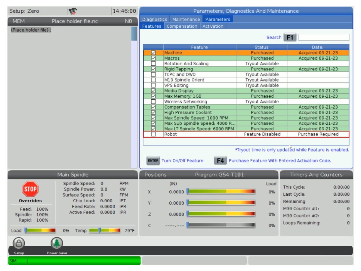
    Robottiominaisuuden lukituksen avausparametri 93-1001031 Sarja aktivoi Haas-koneen robottiominaisuuden. Voit tarkistaa, tarvitsetko tätä sarjaa, siirtymällä Haas-ohjauksen Ominaisuudet- välilehteen ja tarkistamalla, onko robottivaihtoehto korostettu. Tämä sarja ei sisällä fyysisiä osia.
    Kuormatyypin turvaparametrit 93-1000997 Etuautomaation turvaparametrit –  Pakettia tarvitaan, kun cobot lataa osia Haas-koneen etuoven kautta. Tämä sarja ei sisällä fyysisiä osia, ja automaattisyöttö on ostettava ja asennettava erikseen.
    TAI  
    93-1000996 Sivuautomaation turvalliset parametrit –  Sarjaa tarvitaan, kun cobot lataa osia Haas-koneen sivuikkunan kautta. Tämä sarja ei sisällä fyysisiä osia, ja automaatti-ikkunavaihtoehto on ostettava ja asennettava erikseen.

    Tilanne 3 – Cobot siirretään yhdestä koneesta toiseen Haas-koneeseen

    Komponentti Osanumero Kuvaus
    Cobot-integraatiosarja Katso integrointisarjan yhteensopivuustaulukko Osien asentamiseen Haas-koneeseen tarvitaan sarja, jotta ne voidaan liittää cobotiin. Tämä sisältää liitäntärasian, ovikytkimet jne. sekä robotin lukituksen avaustoiminnon parametrin. Tämä sarja on ostettava vain, kun cobot siirretään uuteen Haas-koneeseen, koska nämä osat sisältyvät yleensä toimitukseen, kun cobot tilataan. 
    Kuormatyypin turvaparametrit 93-1000997 Etuautomaation turvaparametrit –  Pakettia tarvitaan, kun cobot lataa osia Haas-koneen etuoven kautta. Tämä sarja ei sisällä fyysisiä osia, ja automaattisyöttö on ostettava ja asennettava erikseen.
    TAI  
    93-1000996 Sivuautomaation turvalliset parametrit –  Sarjaa tarvitaan, kun cobot lataa osia Haas-koneen sivuikkunan kautta. Tämä sarja ei sisällä fyysisiä osia, ja automaatti-ikkunavaihtoehto on ostettava ja asennettava erikseen.
    Turvalaite 08-1899 Monipuolinen valoverhosarja – Sarjaa tarvitaan, jos turvalaitetta EI  siirretä ensimmäisestä koneesta ja toinen Haas-kone tarvitsee oman turvalaitteensa. Tämä sarja muodostaa 4-puolisen suojaesteen.
    TAI  
    08-1948 Viisipuolinen valoverhosarja – Sarjaa tarvitaan, jos turvalaitetta EI  siirretä ensimmäisestä koneesta ja toinen Haas-kone tarvitsee oman turvalaitteensa. Tämä sarja muodostaa 5-puolisen suojaesteen.
    TAI  
    08-1987 Laserin alueskannerisarja –  Sarja tarvitaan, kun turvalaitetta EI  siirretä ensimmäisestä koneesta ja toinen Haas-kone tarvitsee oman turvalaitteensa. Tämän alueskannerin tunnistusetäisyys on 4 metriä.

    Mill Setup

    1

    Suorita seuraavat asiat oven molemmin puolin:

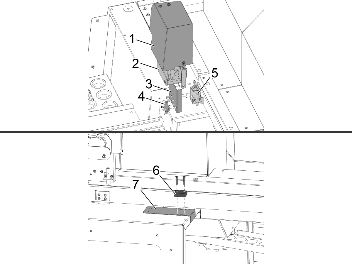
    Irrota automaattioven moottorisuojus [1] ja automaattioven moottorikokoonpano [2].

    Asenna uusi lähestymiskytkimen kiinnike [3] olemassa olevaan lähestymiskytkinlohkoon [5].

    Asenna ovi aina auki -lähestymiskytkin [4] kiinnikkeeseen [3].

     Tärkeää: VMC-sarjaan sisältyy kaksi porausmallia. On olemassa VF-malli [8] ja ainutlaatuinen malli [9], joka on tarkoitettu erityisesti DC-2-koneille. DC-2-mallia tulee käyttää tavallisen VF-mallin sijaan DC-2-koneissa.

    Asenna porasapluuna [7] ovi auki -merkkiä [6] varten ja poraa ja kierteitä 2 x 10-32-reiät oven metallilevyn läpi.

    • Poran koko: #21 tai 5/32"
    • Kierteytä 10-32 NF

    Poista malli ja asenna ovi auki -merkki käyttäen kahta tasapäistä koneruuvia. Asenna automaattioven moottorikokoonpano, kiinnike ja kansi takaisin paikoilleen.

    Säädä lähestymiskytkimen ja ovi auki -merkin välinen korkeus käyttämällä mukana toimitettuja korotuspaloja.

    2

    Edestä täytettävä robotti: 

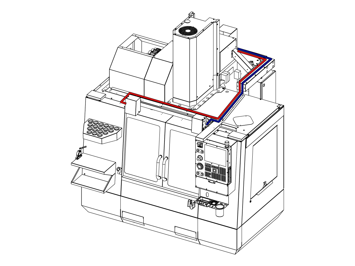
    Vedä ovi täysin auki -kaapelit ohjauskaappiin kuvan osoittamalla tavalla.

    Kytke koneen katkaisin OFF-asentoon.

    Yhdistä 32-0807 PROX NO LEFT DOOR FULLY OPEN SIO  P27 -liittimeen.

    Yhdistä 32-0856 PROX NO RIGHT DOOR FULLY OPEN SIO P72 -liittimeen. 

    Käynnistä koneen virta. 

    3

    Sivusta ladattava robotti:

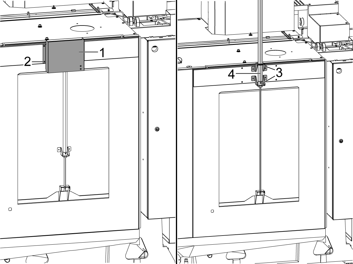
    Poista kansi [1] ja sen kiinnitysosat [2], jotta automaatti-ikkunan ilmasylinteri [4] tulee näkyviin. Nosta ilmasylinteriä [4] niin, että kiinnikkeet [3] ja ilmasylinteri on kiinnitetty kuvan mukaisesti.

    Harmaa ja keltainen paineilmalinjan letku on liitettävä automaatti-ikkunan ilmasylinteriin. Ilmasylinterin porteissa on harmaat ja keltaiset nippusiteet, jotka osoittavat, mihin kukin letku liitetään.

    Asenna kansi [2] automaatti-ikkunan ilmasylinterin päälle.

    4

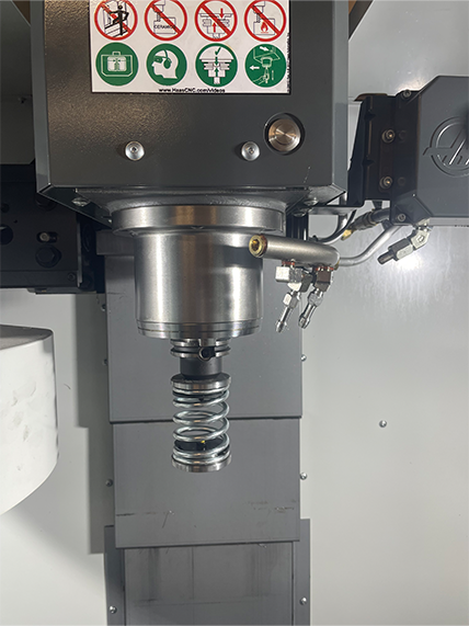
    • Jousityöntäjässä on varsi, joka sopii joko 25 mm tai 1” työkalunpitimeen
    • Tämän työkalun on nostettava työkalunpidin työkalukaruselliin.
    • Ohjelmoi seuraavat vaiheet kaikkien ohjelmien alkuun varmistaaksesi, että kappale on kunnolla kiinni puristimessa: 
      • Etsi kappaleen yläosan jousityöntäjä
      • Siirrä Z-akselia puristaaksesi jousta noin 0,50 tuumaa tai 12,7 mm
      • Avaa puristin yhden sekunnin viiveellä
      • Sulje puristin yhden sekunnin viiveellä

    Huomautus: Jousityöntäjän osanumero on: 

    • 30-12642 JOUSITYÖNTÄJÄ 25 mm:n tai 1,0 tuuman pidike myydään erikseen. 

    Cobot Installation

    1

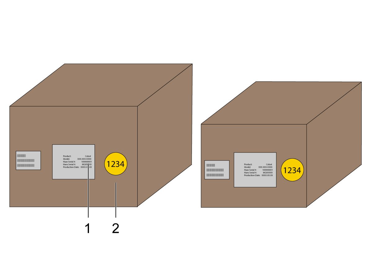
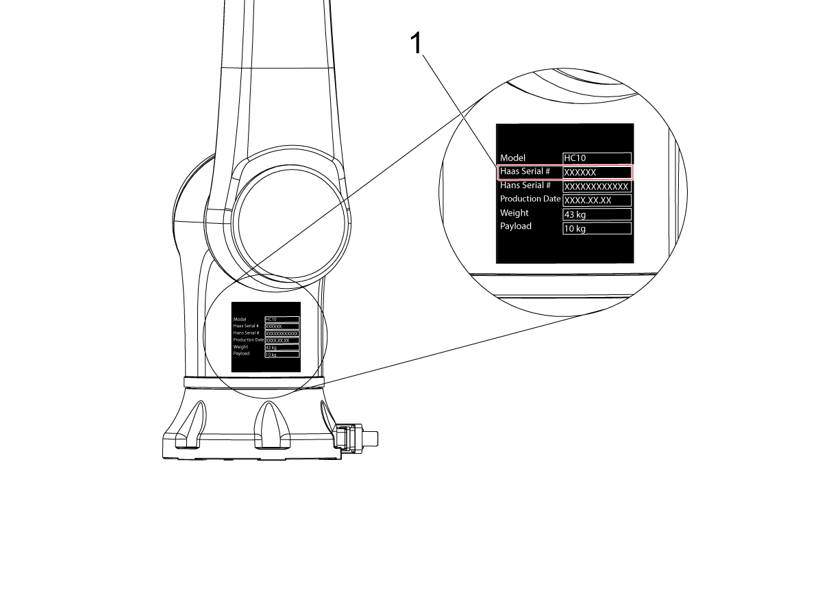
    Varmista, että Cobot ja sen ohjausruutu ovat samasta yhteensopivasta sarjasta vastaavilla sarjanumeroilla. 

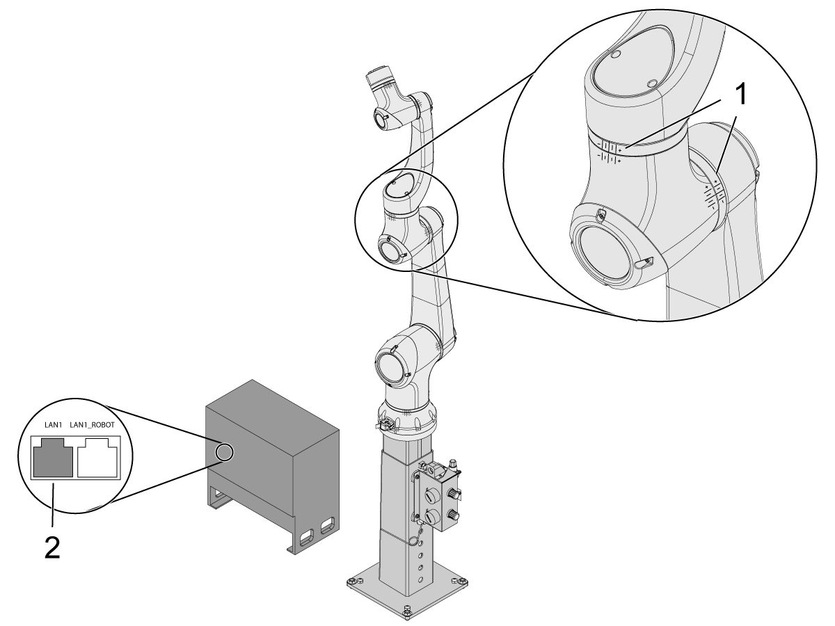
    Haas sarjanumerolla [1] on valkoinen tarra. Varmista, että nämä ovat samat molemmissa rasioissa.

    Laitteessa on keltainen ympyrätarra, jonka tunnistenumero on [2]. Varmista, että nämä ovat samat molemmissa rasioissa.

    2

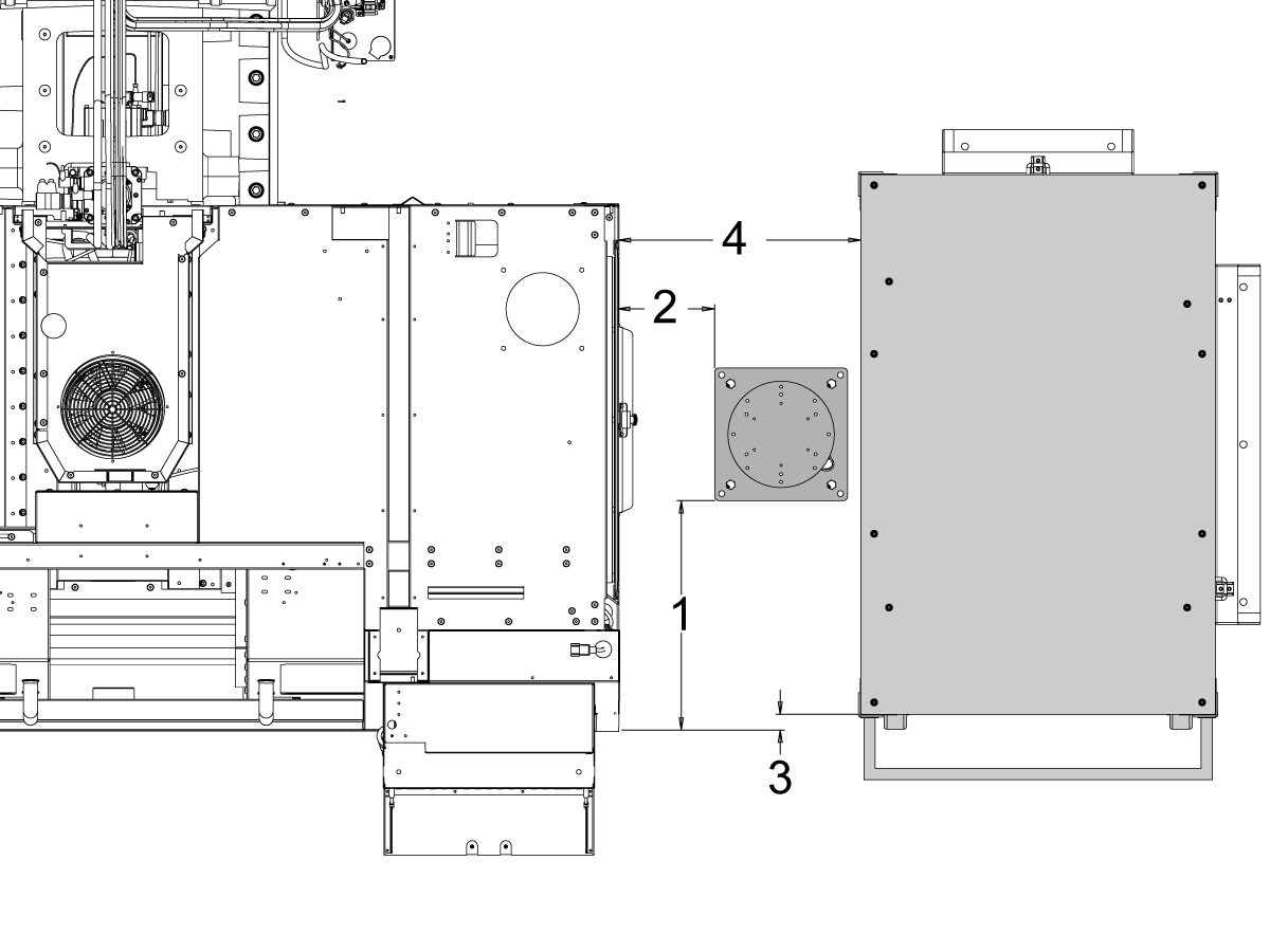
    Mittaa tämä mitta koneen alareunasta pöydän sivupaneeleihin.

     Huomautus: Seuraavat mitat ovat suositeltuja etäisyyksiä. Sijainti voi vaihdella käyttäjän sovelluksen mukaan.

    Käytä seuraavien vaiheiden mittoja viitteenä etu- ja sivulatauksiin käytettäville coboteille. 

    Haas Cobot 10:n pariliittämistä Haas Cobotin jalustaan suositellaan.  Jalusta on riittävän vakaa Haasin määrittelemien osakoko- ja painorajojen mukaisesti käytettäessä. 

    3

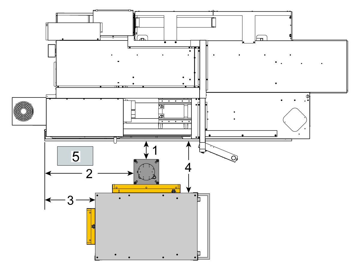
    Edestä täytettävä:

    Sijoita jalusta ja osapöytä seuraavaan paikkaan koneeseen nähden:

    Mitat Brittiläinen mittajärjestelmä (tuumaa) Metrijärjestelmä (cm)
    Koneen etuosasta jalustan etupuolelle [1] 5,5″ 14 cm.
    Koneen vasemmalta puolelta jalustan vasemmalle puolelle [2] 29,5″ 75 cm.
    koneen etuosasta osapöydän etupuolelle [4] 22″ 56 cm.
    Koneen vasemmalta puolelta osataulukon vasemmalle puolelle [4] 10 tuumaa 25,4 cm

    4

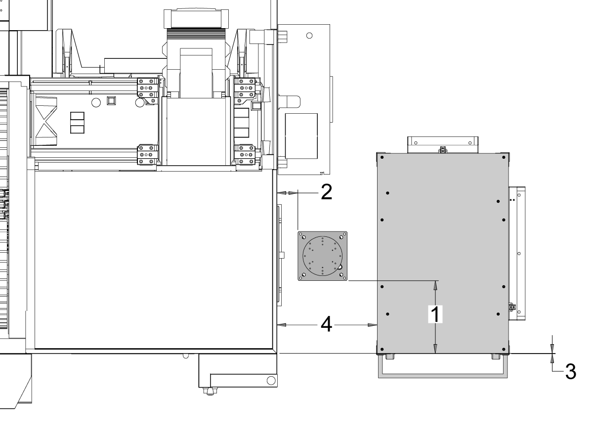
    Sivusta ladattava:

    Sijoita jalusta ja osapöytä seuraavaan paikkaan koneeseen nähden:

    Mitat Brittiläinen mittajärjestelmä (tuumaa) Metrijärjestelmä (cm)
    Koneen etuosasta jalustan vasemmalle puolelle [1] 20,5″ 52 cm.
    Koneen oikea puoli jalustan etupuolelle [2] 8,5″ 21,6 cm
    Koneen etuosasta osapöydän vasemmalle puolelle [3] 1,5″ 3,8 cm
    Koneen oikea puoli osapöydän etupuolelle [4] 21,5″ 54,6 cm

    5

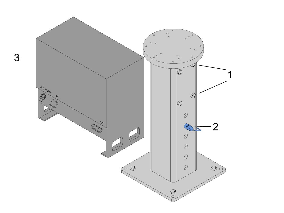
    Kiinnitä jalusta maahan. Tasaa pöytä vatupassin avulla.

    HUOMAUTUS: Säädettävää jalustaa varten aseta haluttu korkeus löysäämällä pidätinruuveja [1] ja säätämällä sitten haarukkatappia [2]. Kiristä pidätinruuvit [1] uudelleen ennen robotin asentamista. Aseta vatupassi jalustan päälle käyttäen (x4) kuusiopultteja alustassa X- ja Y-tasojen tason asettamiseen.

    Aseta Cobot-ohjausrasia [3] suoraan jalustan viereen varmistaaksesi, että kaapelit ovat riittävän löysällä. 

    6

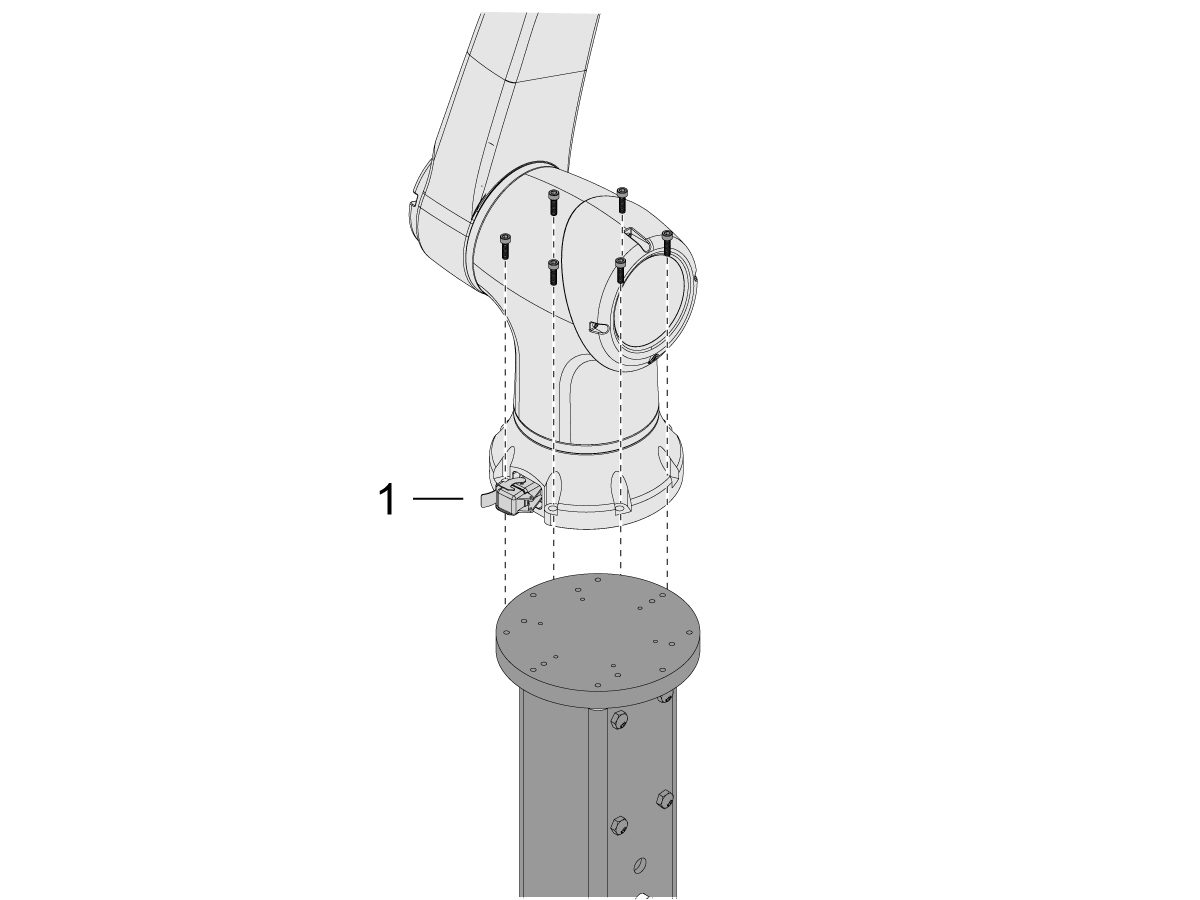
    Poista Cobot kuljetuslaatikosta.

    Huomautus: Asenna adapterilevy tarvittaessa jalustan ja robotin väliin.

    Asenna Cobot jalustan päälle (x6) ruuveilla.

    HUOMAUTUS: Varmista, että cobot-kaapelin liitin [1] on kohtisuorassa koneen etuosaan nähden. 

    TÄRKEÄÄ: Vastaanotin painaa noin 40 lbs ja on nostettava laitteella, jolla voi turvallisesti nostaa kyseisen painon.

    7

    Cobot-pakkauksen sisällä on pieni pussi [1], joka on täynnä varaosia, mukaan lukien: 

    • Sulake
    • Ruuvit (x2)
    • Ohjausrasian avaimet

    Keskikokoinen pussi [2] on täytetty ylimääräisellä M12-liittimellä. Tätä kaapelia voidaan käyttää pääty-I/O-moduulin tulojen ja lähtöjen määrittämiseen. 

    Suurikokoinen pussi [3] on täynnä papereita ja siinä on USB-muistitikku, jossa on ladattu Cobot-ohjelmisto.

    Varmista, että pidät nämä varaosat turvallisessa paikassa tulevaa käyttöä varten. 

    Robot Electrical & Air - Installation

     DANGER: Working with the electrical services required for CNC machines is extremely hazardous and can result in serious injury or death.

    Before connecting line wires to the CNC:

    • Turn off all power to the machine at the source.
    • Perform a Lockout-Tagout (LOTO) procedure to ensure the power remains off during service.
    • Verify that power has been disconnected by using an AC voltage detector on all incoming lines.

    If you are uncertain about how to safely disconnect power or perform LOTO procedures:

    • Do not proceed.
    • Contact qualified personnel or obtain appropriate assistance before continuing.

    Failure to follow these precautions may result in electrical shock, equipment damage, or fatal injury.

     Danger: Before beginning any work inside the control cabinet, verify that the High Voltage indicator light on the 320V Power Supply / Vector Drive has been off for a minimum of five (5) minutes. This waiting period ensures that residual voltage has dissipated and reduces the risk of electric shock.

    Certain service procedures involve high-risk electrical components and may pose serious injury or fatality hazards. Technicians must not attempt any procedure unless they have a complete understanding of the steps involved and the associated risks.

    If there is any uncertainty regarding a procedure, contact your Haas Factory Outlet (HFO) to arrange for a qualified service technician.

    1

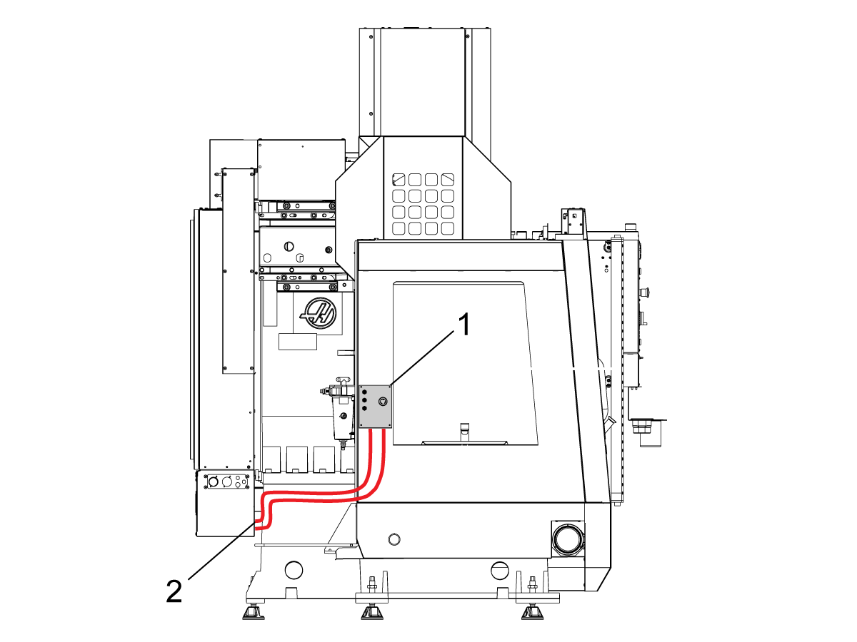
    Liitä liitäntärasia Haas-koneeseen:

    Robotin turvalaitteiden käyttöliittymärasiassa 32-9018 on magneettikiinnikkeet kiinnitettäviksi koneen metallilevyyn. Asenna robotin sähkökytkentärasia [1] kuvan osoittamalla tavalla.

    Reititä robotin käyttöliittymän sähkökaapelit [2] koteloa pitkin magneettikiinnikkeiden ja nippusiteiden avulla. Reititä kaapeli sähkökaapin pohjan läpi.

    HUOMAUTUS: Lisätietoja liitäntärasian päivittämisestä robotin turvalaitteiden liitäntärasiaan on julkaisussa Robotin turvalaitteiden liitäntärasia – Asennus – AD0703. 

    2

    Liitä liitäntärasia Haas-ohjauskaappiin:

    Liitä kaapeli 33-8562C E-STOP-riviliitin TB-1B [1]-liittimeen ja kytke asetustilan riviliitin SIO-piirikortin liittimeenTB-3B [1].   

    Kytke käyttäjärele kohtiin K9 ja  K10 [2].

    Varmista, että hyppyjohdin on asennettu SIO-piirilevyn liitäntään JP1. 

    Liitä saparokaapeli, jossa on merkintä P1 SIO, SIO-piirilevyn P1-liittimeen [3].

    Huom:  Jos koneessa on regeneroitu vektorikäyttö, irrota kaapeli   33-0634 SUODATTIMEN OV IOPCB  P1:tä  varten P1 SIO:sta ja kytke se liittimen SUODATTIMEN OV-SIIRROKSEEN kaapelissa    33-8562C. Jos koneessa ei ole regeneroitua vektorikäyttöä , älä kytke mitään liittimeenFILTER OV FAULT.

    Liitä RJ-45 -kaapeli [4] Ethernet–USB-adapteriin [5] (osanro 33-0636).   Liitä USB-liittimen pää Maincon-piirilevyn  J8 -yläporttiin. Lisää ferriittisuodatin [6]  USB-adapteriin.   

    Kiinnitä 24 VDC -virtalähde [7] ohjauskaapin vasemmalle puolelle ja kytke se liitäntään24V PS kaapelissa 33-8562C. Liitä kaapeli 33-1281 [8] 24VDC-virtalähteeseen [7] ja kytke P3 kohtaan PSUP PCB 

    .

    3

    MM/SMM CM/CL -koneille, joissa ei ole XMR:ää

    Jos P3:ssa on hyppyjohdin, joka on kytketty P3:sta [10] P7:ään [9] PSUP-piirikortissa, tarvitaan jakajakaapeli, jotta 24VDC:n virtalähde [7] voidaan kytkeä PSUP:n 120VAC:n liittimiin. Liitä jakokaapelin urosliitin P3:een [10] ja liitä sitten hyppyjohdin kyseisestä kaapelista P7:ään [9] ja myös kaapeliin 33-1281 [8].

    Huomautus: Varmista, että hyppyjohdin on liitetty kohtaan, jossa punainen linjautuu jakokaapelin punaisen kanssa.

    4

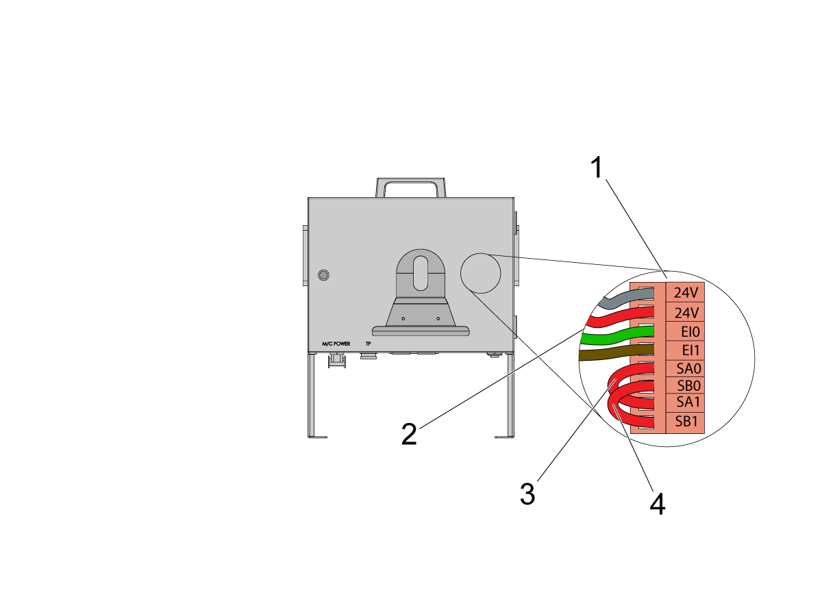
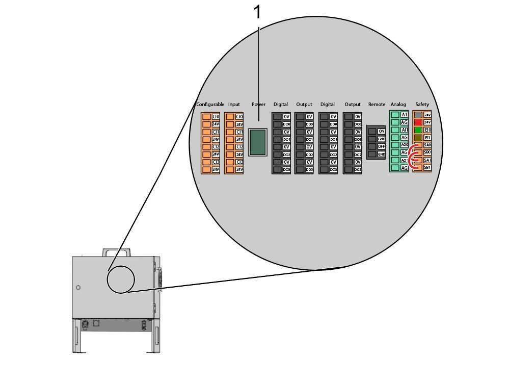
    Asenna osa robotin signaalikaapelista Cobotin ohjausrasian sisälle(33-1272 tai 33-1351).   Tämä tehdään poistamalla turvaliitin [1] Cobotin  ohjausrasiasta, jotta eriväriset johdot voidaan asentaa niiden kunkin sijaintiin 

    33-1272 / 33-1351-kaapelit [2], jotka menevät turvaliittimeen:

    • Harmaa johto ylimpään 24V
    • Punainen johto pohjaan 24V
    • Vihreä johto EI0:een
    • Ruskea johto EI1:een
    • Hyppyjohdin [3] SA0 :sta SA1
    • :een
    • Hyppyjohdin  [4] SB0 :sta SB1
    • :een

     HUOMAUTUS: Muita tämän kaapelin johtoja ei käytetä. Laita jokaiseen johtoon hieman sähköteippiä ja sido jäljelle jääneet käyttämättömät johdot nippusiteellä. 

    5

    Tärkeää: Kun olet asentanut kaikki kaapelit robotin signaalikaapelista, varmista, että sulake [1] pysyy aina asennettuna Cobotin ohjausrasian suojaamiseksi. 

    6

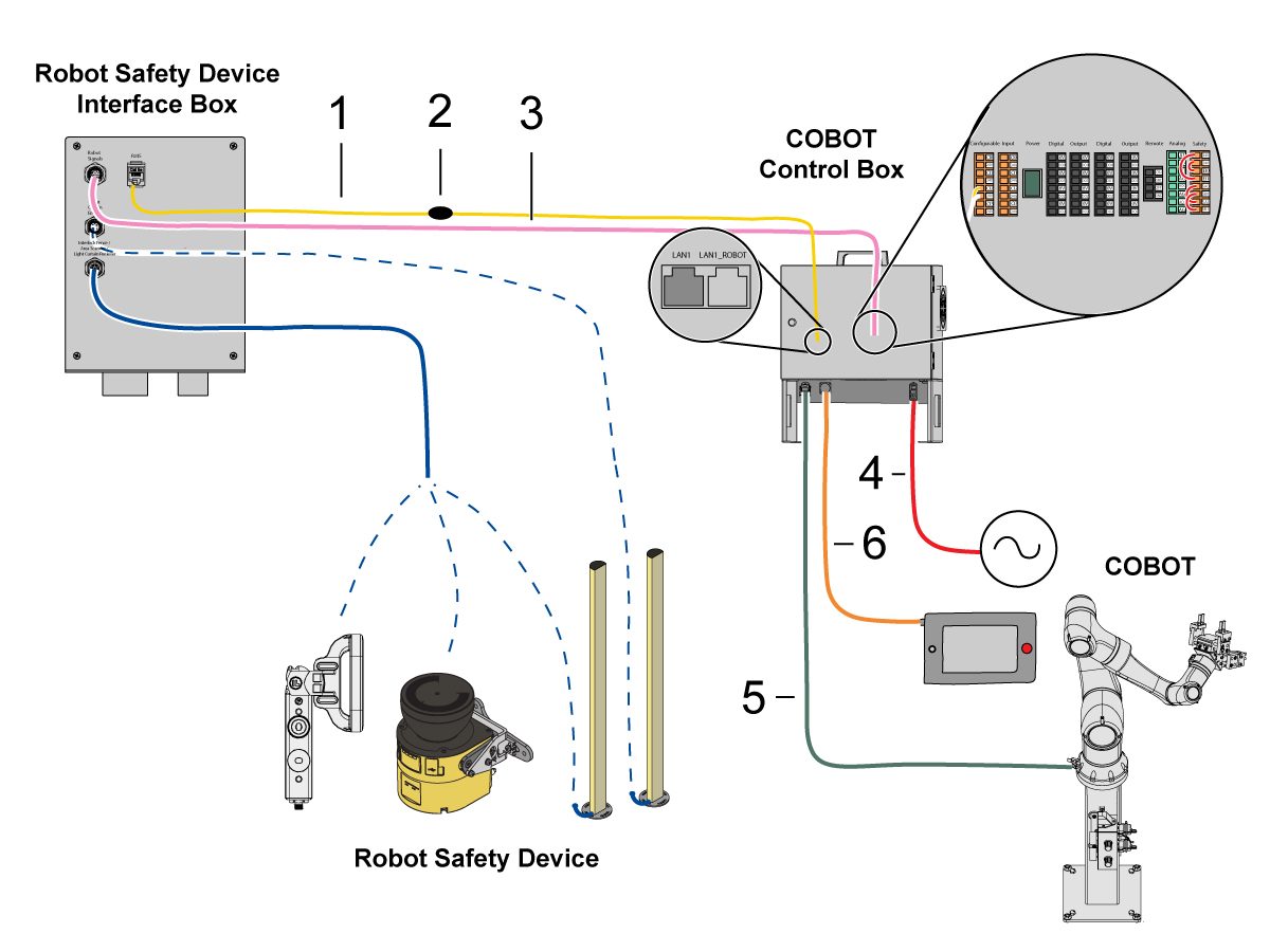
    Liitä Cobot liitäntärasiaan: 

    Kytke RJ45-Ethernet-kaapeli [1] Cobotin ohjausrasiasta liitäntärasiaan. Lisää ferriittisuodatin [2] RJ-45-kaapeliin.  

    Liitä robotin signaalikaapeli [3] Cobotin ohjausrasiasta liitäntärasiaan. 

    Liitä 120 VAC:n Cobot-virtakaapeli [4] ulkoiseen virtalähteeseen.  

    Liitä robotin virtajohto [5] ohjausrasiasta Cobotiin.

    Liitä ohjaustaulun kaapeli [6] ohjausrasiasta ohjaustauluun. 

    HUOMAUTUS: Lisätietoja lukitusaidan, alueskannerin tai valoverhon asennuksesta on alla olevassa Robotin turvalaite -osiossa.

    7

    Varmista, että kauko-ohjain on asennettu koneeseen.

    HUOMAUTUS: Lisätietoja RJH-XL-asennuksesta on kohdassa Etätyökahva – Suuri kosketusnäyttö (RJH-XL) – Asennus – AD0533. 

    8

    Vaiheet 7–10 ovat pneumaattisten tarttujien johdotus- ja letkureititysohjeita. Katso mekaanisen asennuksen ohjeet tarttujien asennusosiosta, joka on alempana tällä sivulla.

    Asenna kaksoisilmasolenoidi kokoonpanojalustan sivulle ja anna samalla paineilmalinjoille riittävästi löysää. Varmista, että se ei ole tiellä. Reititä koneen alla oleva paineilmalinja [1] takaisin kohti CALM-kaappia kuvan osoittamalla tavalla.

    9

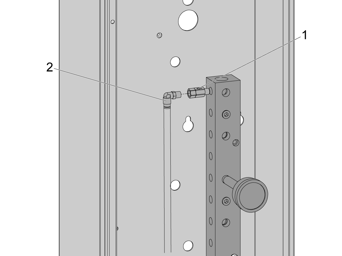
    Irrota tulppa CALM-kaapin sisältä yhdestä CALM-jakotukkiportista ja asenna takaiskuventtiili [1] (58-1863) portin liittimeen. Reititä tulopaineilmalinja [2] kaksoisilmasolenoidikokoonpanosta (edellisestä vaiheesta) CALM-kaappiin ja liitä paineilmalinja takaiskuventtiiliin.

    Kytke koneen ilmansyöttö päälle.

    10

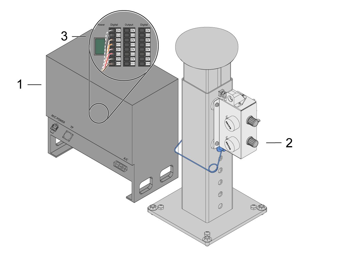
    Varmista, että ohjausrasian [1] virta sammutetaan.

    Liitä kaksoisilmasolenoidikokoonpanon [2] solenoidikaapeli Cobotin ohjausrasian digitaaliseen ulostuloon [1]. Irrota liitin Cobotin ohjausrasiasta.

    11

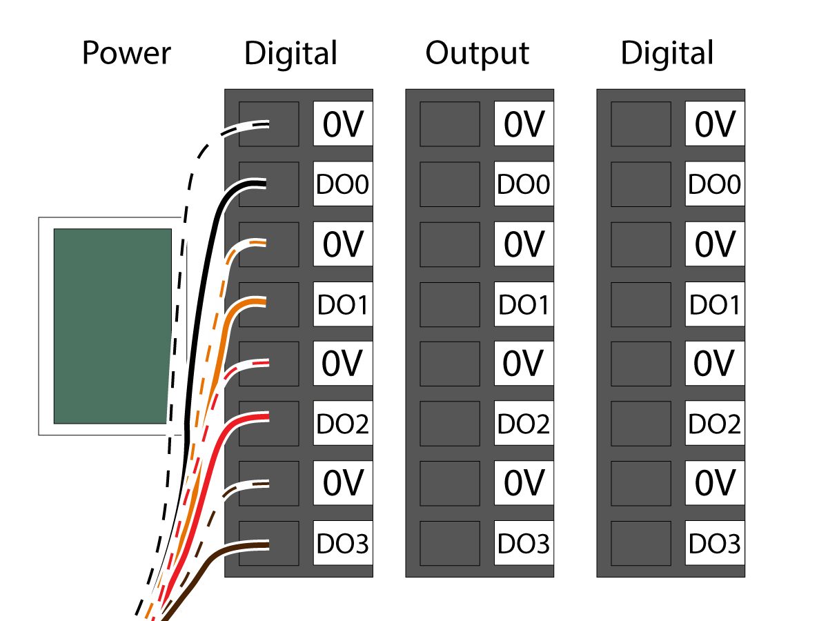
    Liitä tarttujan solenoidin virtakaapeli (33-1276 / 33-1341) digitaaliulostuloliittimeen ohjausrasian sisällä.  Asenna eriväriset johdot kohtiinsa:

    • Musta/valkoinen kaapeli kohtaan 0V
    • Musta kaapeli kohtaan DO0
    • Oranssi/valkoinen johto liitäntään 0V
    • Oranssi kaapeli DO1:een
    • Punainen/valkoinen johto liitäntään 0V
    • Punainen kaapeli DO2:een
    • Ruskea/valkoinen johto liitäntään 0V:een
    • Ruskea kaapeli DO3:een

    Käynnistä ohjausrasian virta.

    Robot Safety Device

    TÄRKEÄÄ: ÄLÄ KÄYTÄ ROBOTTIA, ENNEN KUIN OLET MÄÄRITTÄNYT TURVALAITTEEN ASETUKSET JA TESTANNUT SEN TOIMINNAN.

    Valoverho:

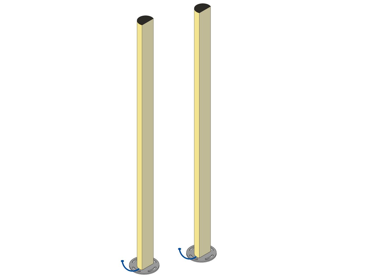
    Cobot-laitteiden oletusturvalaitteeksi toimitetaan valoverhon lähetin ja vastaanotin. Noudata alla olevia valoverhon asennusohjeita: 

    Valoverhon asennus

    HUOMAUTUS: Jos on tilattu alueskanneri tai HC10-konevalmis sarja, käytössä on myös 1M-valoverhovastaanotin ja -lähetin. Nämä toimitetaan kaikkien Cobot-robottien mukana.

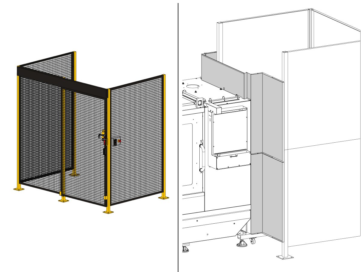
    Robottiaita:

    Jos kone on varustettu aidalla, robottiaita ja oven lukituskokoonpano on asennettava koneeseen. Noudata alla olevia asennusohjeita:

    Robotin aidan asennus

    Kun aita on asennettu, asenna sen jälkeen aitapaneeli koneen ja robotin aidan väliin.

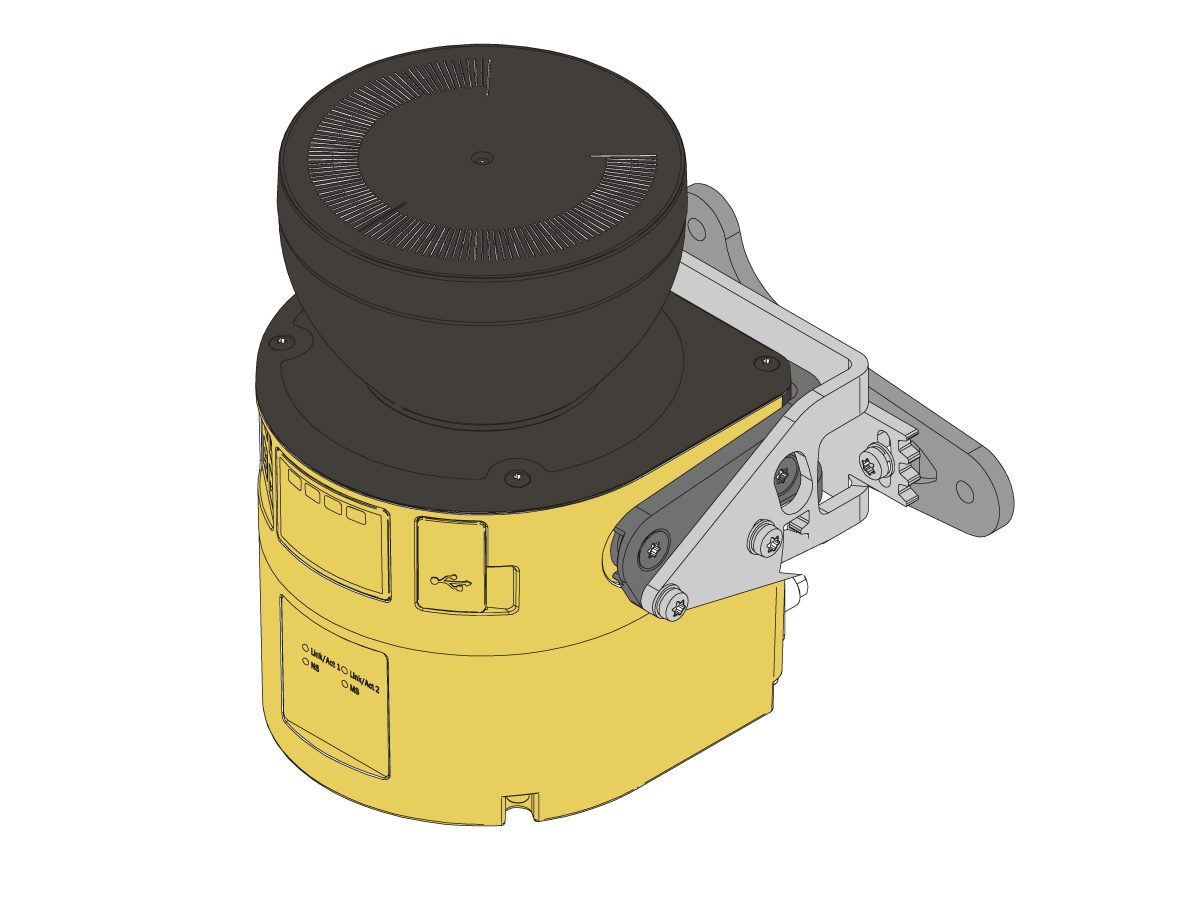
    Alueskanneri:

    Jos koneessa on alueskannerivaihtoehto, alueskanneri on asennettava ja määritettävä tilaan. Noudata alla olevia asennusohjeita: 

    Alueskannerin asennus

    First Power-UP

    1

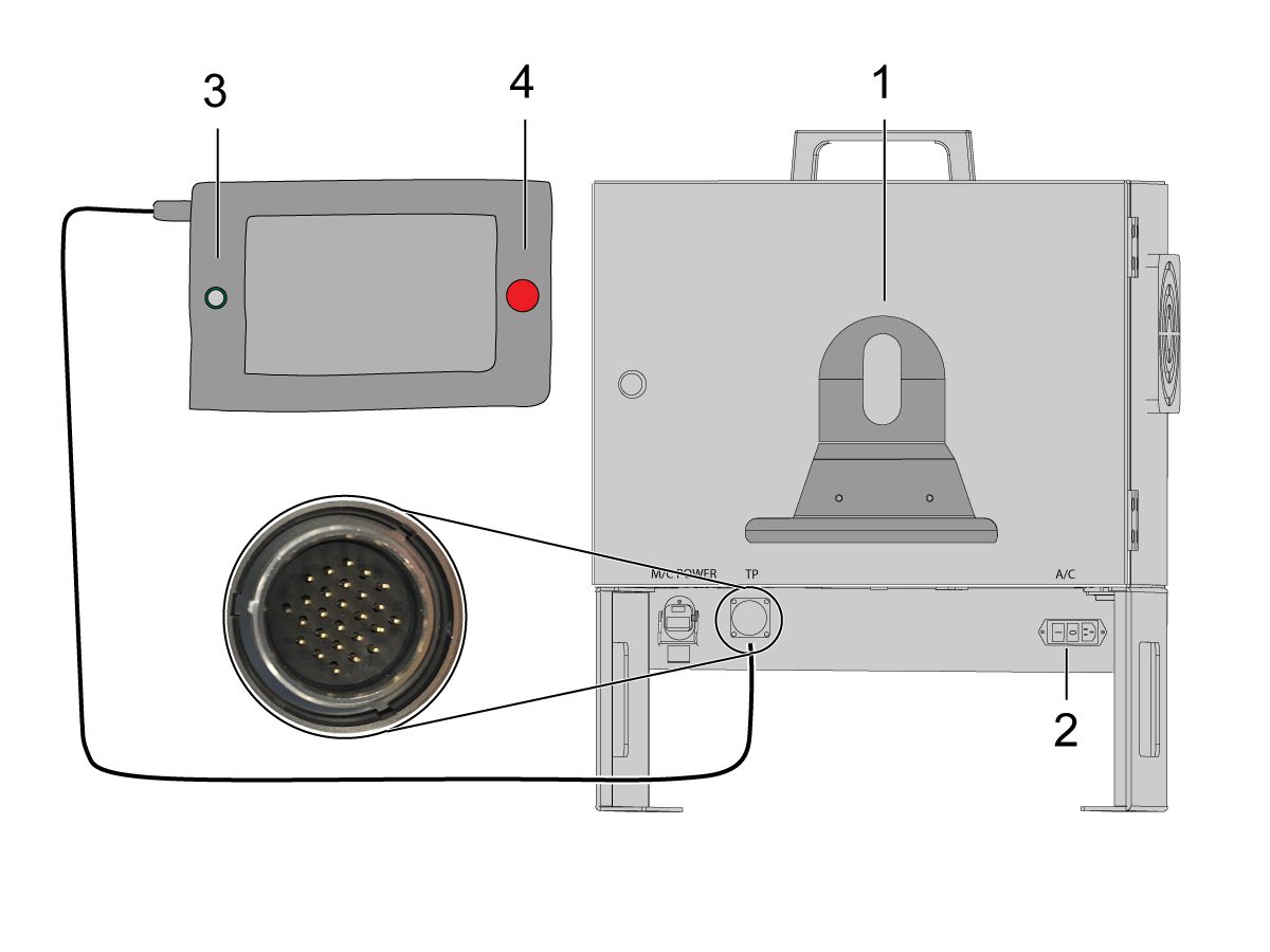
    Asenna ohjaustaulun pidike [1] Cobotin ohjauskotelon etuosaan. 

    Kytke Haas-koneen virta päälle. 

    Kytke Cobotin ohjausrasia päälle kääntämällä virtakytkintä [2].

    Kytke Cobotin ohjaustaulu päälle painamalla ympyrää [3]. 

    Varmista, että ohjaustaulun [E-STOP] [4] on vapautettu. 

    2

    Huomautus: Cobot-ohjaustaulu saa ponnahdusikkunan, jossa pyydetään syöttämään käyttäjätunnus ja salasana. Käytä näitä valtuustietoja kirjautuaksesi opetusohjaustauluun:

    • Käyttäjänimi: ”admin”
    • Salasana: ”admin”

    Siirry suoritustilaan. Paina Ota käyttöön. 

    Mene nykäyssyöttötilaan [1].

    Siirrä jokainen nivel nollakohtaan Siirrä nolla -painikkeilla [2]. 

    3

    Kun robotti on nolla-asemassa, varmista, että hajautusviivat [1] kohdistuvat Cobotin kummankin nivelen jommallekummalle puolelle. 

     TÄRKEÄÄ: Jos jokin nivelen hajautusviiva [1] ei kohdistu, nykäyssyötä tiettyä niveltä vastaavasti, kunnes kaikki hajautusviivat [1] ovat linjassa. Tämä asema asetetaan seuraavassa vaiheessa uudeksi Cobotin nolla-asemaksi.  

    Liitä ethernet-kaapeli [2] Cobotin ohjausrasiasta tietokoneeseen.

    Muuta tietokoneella adapterin asetusta Ethernet-portin käyttöönottamiseksi. 

    Huomautus: Katso adapterin asetusten muuttamisohjeet seuraavista vaiheista.

    4

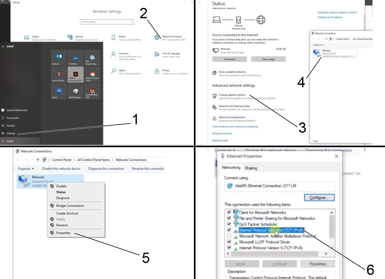
    Voit muuttaa adapterin asetuksia avaamalla tietokoneen asetussivun [1] ja napsauttamalla sitten Verkko ja Internet [2], jolloin näkyviin tulee verkon tilasivu.

    Napsauta Muuta adapterin asetuksia [3] ja sitten hiiren oikealla painikkeella Ethernetiä [4] ja avaa ominaisuusikkuna [5]. Valitse sieltä Internet Protocol Version 4 (TCP/IPv4) [6] -vaihtoehto ja napsauta Ok . 


    5

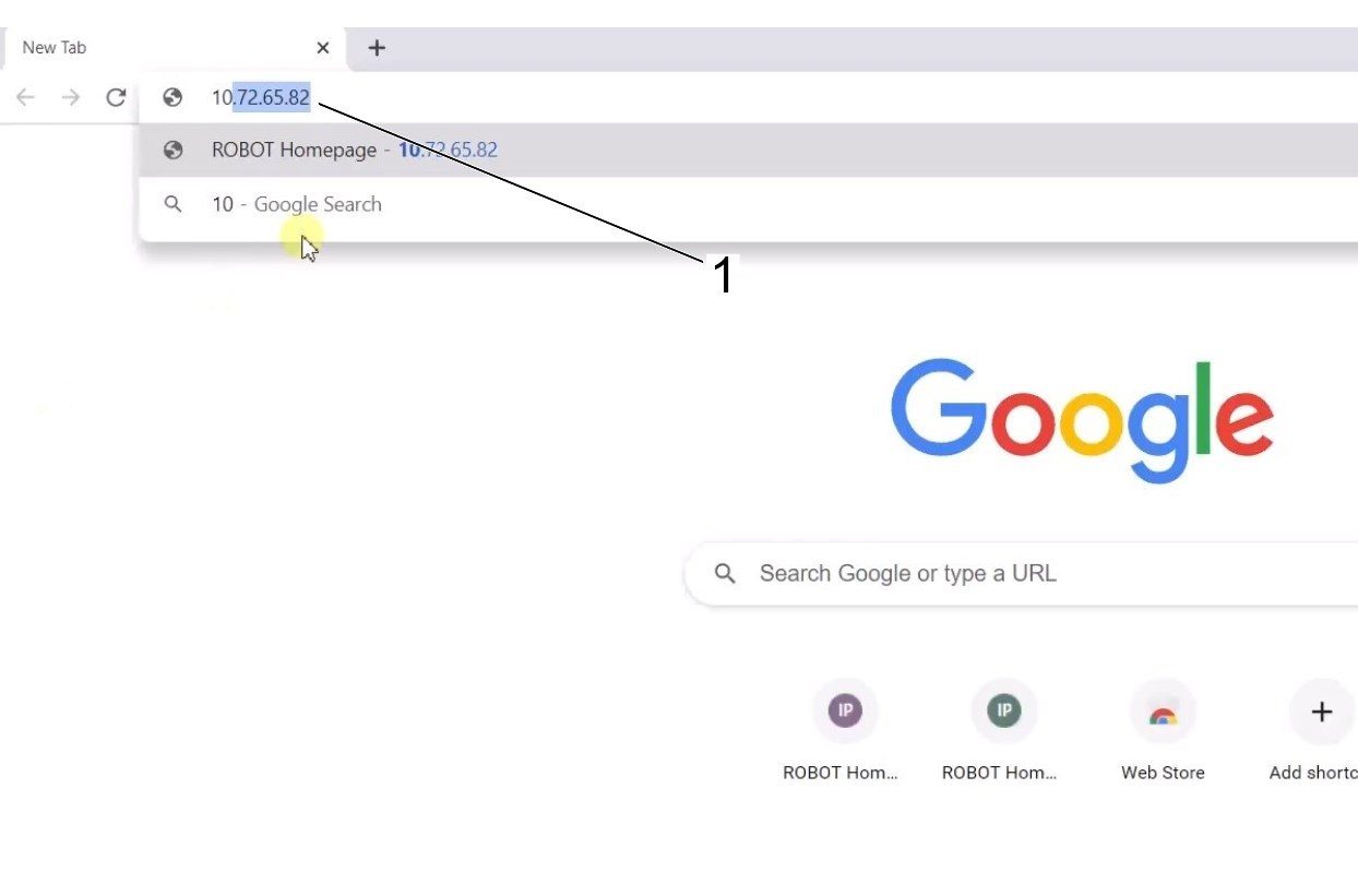
    Ethernet-asetukset ovat nyt oikein. Avaa verkkoselaimen ikkuna ja kirjoita cobotin IP-osoite[1]. 

    Huomautus: Tämä on sama prosessi kuin kannettavan tietokoneen yhdistäminen HRP-1/2/3-järjestelmään. Lisätietoja yhteyden muodostamisesta cobotiin Ethernetin kautta on HRP-Vianmääritys -sivun videossa, joka on osiossa Yhdistä ja nykäyssyötä Haas-robotti. 

    6

    Lataa HRTool HBC:n kautta. Siirry HBC:n Huolto-osiossa kohtaan Apuohjelmat > Asiakirjat ja ohjelmistot > 01 ohjausohjelmisto > 01 Seuraavan sukupolven ohjaus > 10 Cobot-ohjelmisto > HRTool.zip.

    Pura kansio ja siirry kohtaan HRToolsMaind.exe.

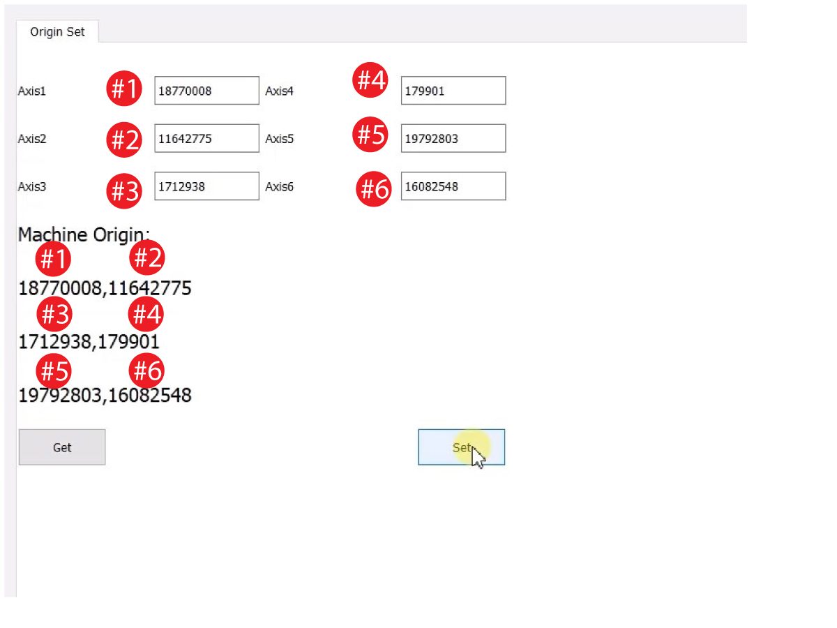
    Lisää Järjestelmät-välilehden Cobotin IP-osoite.  Napsauta asetuspainiketta. 

    Siirry HRTool-työkalun Konfigurointi-välilehteen.

    Napsauta ”"hanki"” nähdäksesi todelliset vs. teoreettiset enkooderiarvot. 

    Napsauta ”"Aseta”, jotta voit asettaa teoreettisen arvon todellisiin enkooderin arvoihin." Tämä vaihe asettaa Cobotin nykyisen aseman uudeksi kotiasennoksi. 

    7

    Varmista, että kunkin nivelen todelliset ja teoreettiset enkooderiarvot vastaavat toisiaan. 

    HUOMAUTUS: Jos arvot eivät täsmää, paina uudelleen ”"Aseta”. "

    8

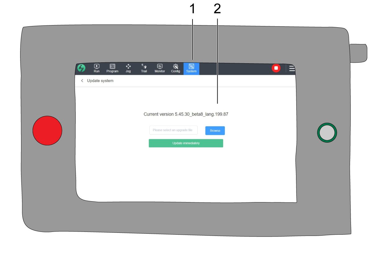
    Siirry ohjaustaulussa kohtaan Järjestelmä [1] ja sitten Päivitä järjestelmä. 

    Varmista, että Cobotin laiteohjelmisto [2] on toinen seuraavista:

    • HR5.51H.16.beta.20231213.zip
    • HR6.4.9.tmp.20240919.zip

    HUOMAUTUS: Laiteohjelmaversio HR6.4.9.tmp.20240919.zip on yhteensopiva kaikenkokoisten cobotien kanssa.

    Katso laiteohjelmiston päivitysohjeet kohdasta Haas Cobot – Huolto.  

    9

    Palauta kaikki akselit nollaan Haas-ohjaustaulussa.

    Liitä huolto-USB-avain.  Siirry huoltotilaan.

    Siirry Parameters> Factory-välilehdelle.  Muuta seuraavat:

    • 1278 [1278:] Robot Ready E-Stop Enabled arvoksi TRUE
    • 2191 [694:] LIGHT CURTAIN TYPE arvoksi LC_TYPE_1
    • 2195 [:] Ota käyttöön etuluukun täydellisen avaamisen kytkin arvoon TRUE
    • 2196 [:] Ota käyttöön vasemman luukun täydellisen avaamisen kytkin arvoon TRUE  
    • 2192 [:] Light Curtain Trigger Threshold arvoksi 0

    Paina[SETTINGS].

    Määritä asetukset:

    • 372 Parts Loader Type arvoksi 3: Robot.
    • 376 Light Curtain Enabled arvoksi On

    10

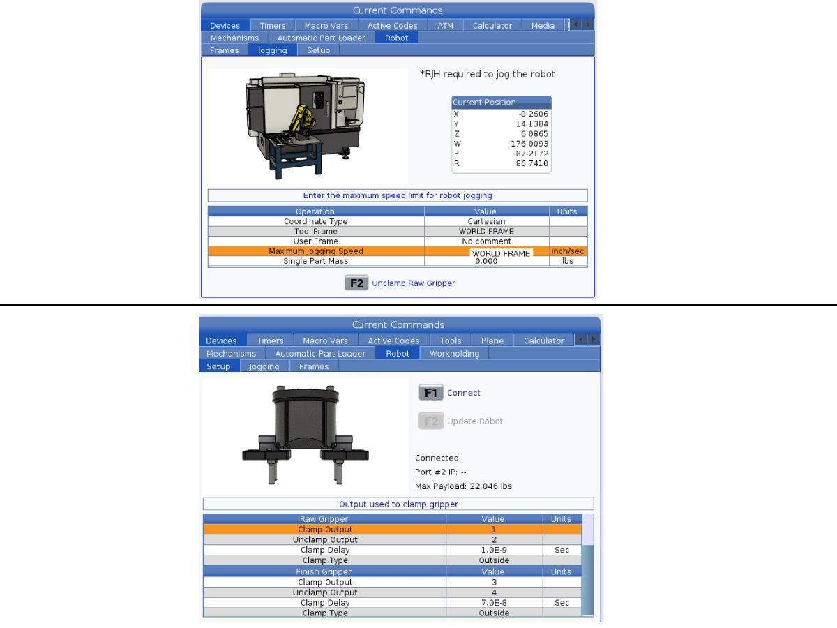
    Paina Haas-ohjaustaulussa [CURRENT COMMANDS].

    Siirry  Devices>Robot>Jogging -välilehdelle. Muuta seuraavat: 

    • Maximum Jogging Speed arvoksi 7,9  in/s

     Huomautus: RJH:n nykäyssyötön inkrementit ovat prosenttiosuus tästä maksiminopeuden arvosta. Jotta robotin liikematka jokaisen nykäyssyöttöpyörän nykäyksen kohdalla pienenisi, sinun on muutettava suurin nykäyssyöttönopeus pienempään arvoon.

    Siirry Setup -välilehdelle. Muuta seuraavat:

    • Robotin enimmäisnopeus   118 in/s  (2 000 mm/s).
    • Syötä  tarttujan nettomassa. Katso pohjakaavio verkkosivustoltamme (YKSITTÄISTARTTUJAN POHJAKAAVIO tai  KAKSOISTARTTUJAN POHJAKAAVIO), jotta saat oikean arvon tälle asetukselle.
    VAROITUS: Jos tämä arvo asetetaan väärin, robottivarsi ei ehkä liiku oikein. 
     
    • Number of Grippers tarttujien lukumääräksi.
    • Raw Gripper Clamp Output arvoksi 1
    • .
    • Raw Gripper Unclamp Output arvoksi 2.
    • Raakatarttujan puristimen viiveen  kiinnityksen/irrotuksen kestoksi sekunteina. 
    • Raw Gripper Clamp Type arvoksi OD/ID.
    • Finish Gripper Clamp Output arvoksi 3.
    • Finish Gripper Unclamp Output arvoksi 4.
    • Finish Gripper Clamp Delay kiinnityksen/irrotuksen kestoksi sekunteina.
    • Raw Gripper Clamp Type arvoksi OD/ID.

    Ohjaustaulun sulkeminen

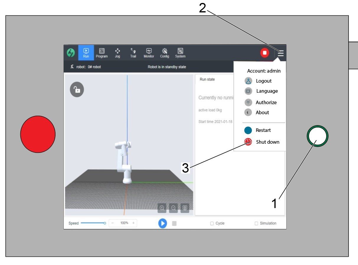
    Varoitus: Älä käytä ohjaustaulun virtapainiketta [1] sen virran sammuttamiseen. Tämä voi aiheuttaa järjestelmätiedostojen menetyksen Cobot-ohjausrasiassa.

    Voit sammuttaa ohjaustaulun virran painamalla oikeassa yläkulmassa olevia kolmea viivaa [2], jolloin oikealla oleva asetusvalikko tulee näkyviin.

    Valitse Sammuta virta -vaihtoehto [3] käynnistääksesi Cobotin ohjausrasian virrankatkaisujakson.

    Tärkeää: Ohjaustaulu virran sulkeminen väärin voi vahingoittaa Cobotin ohjausrasian kriittisiä tiedostoja. Tämä voi johtaa siihen, että Cobotia ei voi käyttää, ennen kuin järjestelmätiedostot asennetaan uudelleen ohjausrasiaan.


    Security Risk Level

    1

    TÄRKEÄÄ: Ennen asennusta on suoritettava asianmukainen riskinarviointi ja täytettävä asianmukaiset turvallisuusvaatimukset. 

    2

    Aseta asianmukainen turvallisuusriskitaso Cobotin ohjaustauluun riskiarvioinnin perusteella. Siirry kohtaan Konfigurointi > Yleiset rajoitukset ja napauta haluamaasi turvallisuusriskitasoa [1] 0–5.

    Käytä turvatarkistuksen  ”admin”-koodia turvallisuustason muuttamiseen.

    HUOMAUTUS: Kun turvallisuusriskitaso on pienempi, robotin enimmäisnopeus, voima jne. on pienempi. Kun turvallisuusriskitaso on suurempi, robotin enimmäisnopeus, voima jne. on suurempi.

    Tämä turvallisuusriskitaso laskee suurimman sallitun voiman, nopeuden, tehon, momentin, kulmayhteen nopeuden ja kulmayhteen voiman [2], jonka Cobot kestää ennen hälytyksen 9150.10017 törmäyksenestovirheen laukeamista. 

    TÄRKEÄÄ: Robotin ohjelmoitu nopeus ei voi olla suurempi kuin sallittu nopeus turvallisuusriskitasolta. 

    HUOMAUTUS: Lisätietoja hälytyksistä on Haas Cobot -vianmääritysoppaassa. 

    Activation

    1

    Mene HAAS SERVICE -portaaliin ja lataa uusimmat määritystiedostot.

    Lataa turva-automaatiovaihtoehdon etu-/sivukokoonpanotiedostot.

    Lataa ohjaukseen asetusmääritysten korjaustiedosto. Katso toimintaohje SEURAAVAN SUKUPOLVEN OHJAUS – KOKOONPANOTIEDOSTO – LATAAMINEN/LATAA.

    2

    Siirry kohtaan Parametrit > >Ominaisuudet >Robotti ja varmista, että robotin ominaisuus on näkynyt alareunassa.

    3

    Paina[CURRENT COMMANDS].

    Siirry Devices>Robot>Setup-välilehdelle [1].

    Paina [E-Stop].

    Paina [F1]robotin yhdistämiseksi [2].

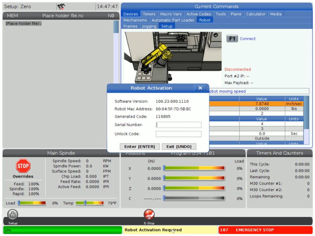
    Kun robotti liitetään koneeseen ensimmäistä kertaa, robottiominaisuuden lukitus on avattava. Tämä ponnahdusikkuna näyttää koneen nykyisen ohjelmistoversion, robotin mac-osoitteen ja luodun koodin. Syötä nämä tiedot HBC:hen saadaksesi lukituksen avauskoodin.

    4

    Siirry HBC:ssä Huolto-välilehteen [1].

    Napsauta näytön vasemmalla puolella Aktivoinnit [2] ja valitse sitten Cobotin asennus [3] aloittaaksesi prosessin, jotta saat cobotin lukituksen avauskoodin.

    Ensimmäinen vaihe on syöttää koneen sarjanumero [4] ja Cobotin sarjanumero [5] HBC:n kenttiin.

    Kun olet syöttänyt oikeat tiedot, paina oikeassa alakulmassa Seuraava [6] ja jatka vaiheiden läpi, kunnes saat avauskoodin.

    Huomautus: Varmista, että olet Cobotin asennus -välilehdellä [3] etkä robotin asennus -välilehdellä. Robottiasennusta käytetään vain Haas-robottipakkauksille. Robottiasennuksen käyttö Haas Cobot -robottien kanssa johtaa virheelliseen avauskoodiin.

    5

    Syötä Cobotin Haas-sarjanumero[1] ja lukituksen avauskoodi robotin liittämiseksi koneeseen. 

     Huomautus: Vain HFO-huoltoteknikko voi suorittaa tämän vaiheen.

     Huom: Kone on aktivoitava ennen kobotin aktivointia. Noudata  Koneen aktivointi / ajan pidennys – NGC  -toimintamenettelyä. 

    Kun robotti on yhdistetty koneeseen, Haas-näytön alareunaan pitäisi ilmestyä keltainen viesti, jossa sanotaan, että robotin aktivointi onnistui. 

    6

    Vapauta hätäpysäytyspainike [E-STOP] ja paina RESET (Nollaus) poistaaksesi hälytyksen. 

    Paina [HANDLE JOG]-painiketta. 

    Paina [CURRENT COMMANDS]  ja siirry Devices > Robot > Jogging-välilehdelle.

     Huom: Robottia voidaan käyttää nykäyssyötöllä asetustilassa vain, kun  F2 -näppäintä RJH painetaan. Katso kohtaa Asetus/käyttötila jäljempänä.

    Paina kosketusnäyttöisen kauko-ohjaimen Joint-painiketta nivelkoordinaatteihin siirtymiseksi.

    Siirrä robotti helppopääsyiseen paikkaan, jotta voit asentaa tarttujat.

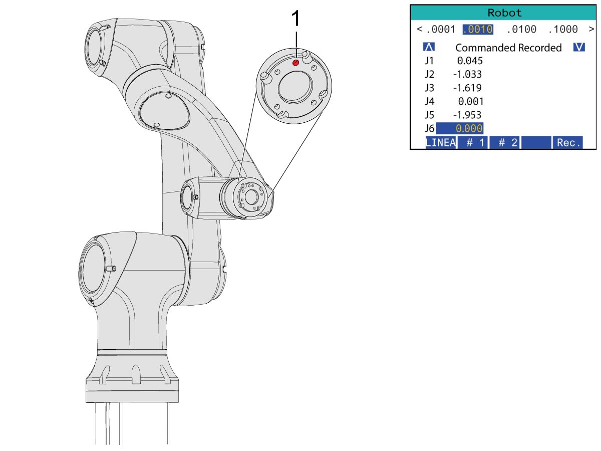
    Nykäyssyötä J6 asemaan 0,0000.

    Paikoitusreikä on keskitettävä päälle.

    Huomaa: Paina [Emergency Stop] ennen robotin käsittelyä.

    Gripper Installation

    1

    Sammuta koneen ilmansyöttö kääntämällä ilma-/voiteluainekaapin venttiiliä ja vetämällä paineenalennusventtiiliä järjestelmän ilman vapauttamiseksi.

    2

    Kaksitoiminen tarttuja:

    Tässä osassa on kaksi versiota kaksitoimisista tarttujista, joilla molemmilla on sama asennusprosessi.

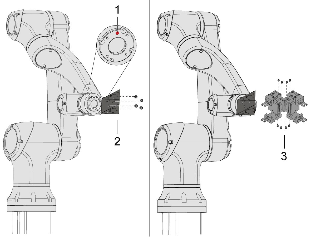
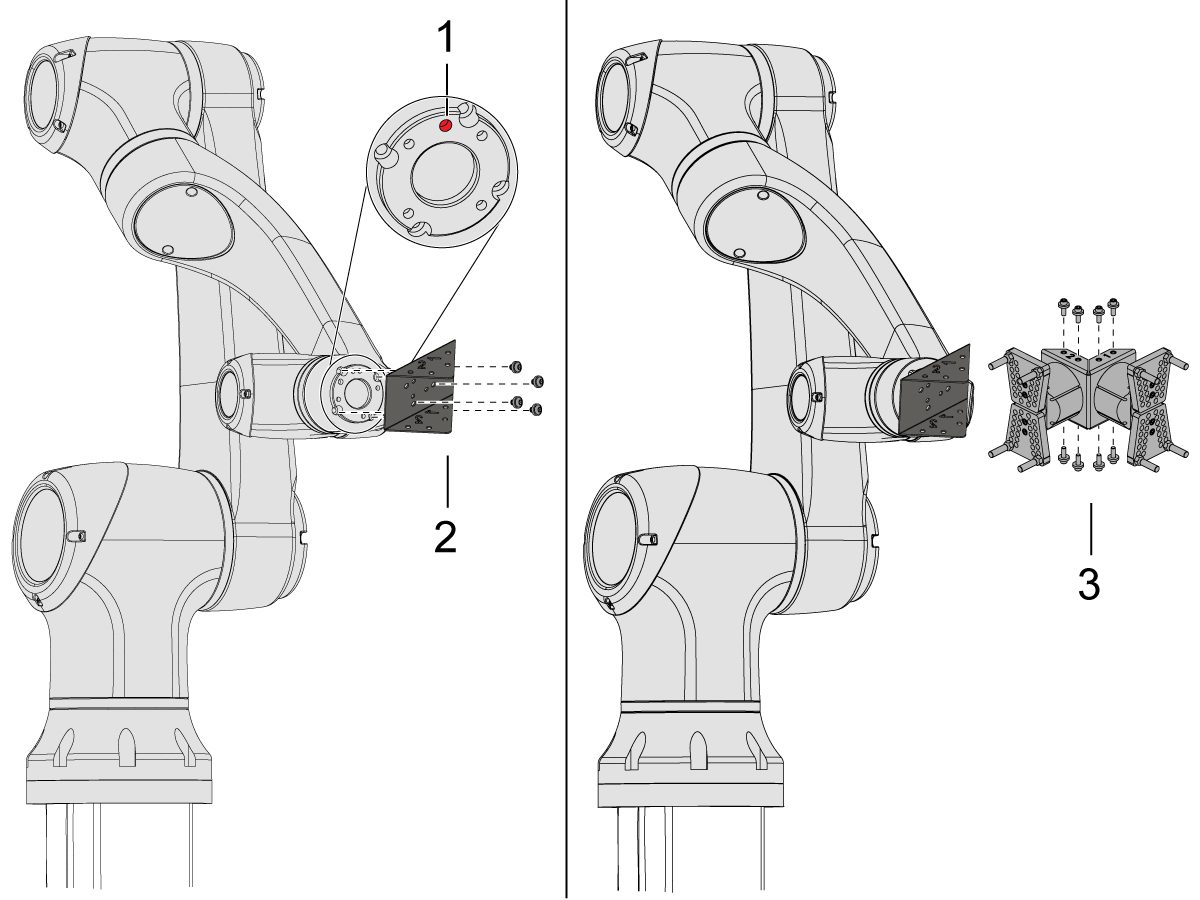
    Nykäyssyötä robottia niin, että paikannusreikä [1] on keskellä yläosaa.

    Asenna adapterilevy [2] robottivarren päähän.

    Asenna kaksoistarttuja [3] adapterilevyyn [2].

    HUOMAUTUS: 

     Varmista, että asennat tarttujan 1 (jossa on oranssit ja violetit nippusiteet) tarttujan 1 adapterilevyosaan.

    3

    Suorakulmainen yksitoiminen tarttuja

    Nykäyssyötä robottia niin, että paikannusreikä [1] on keskellä yläosaa.

    Asenna kulma-adapterilevy [2] robottivarren päähän.

    Asenna yksittäistarttuja [3] kulmikkaaseen adapterilevyyn [2].

    4

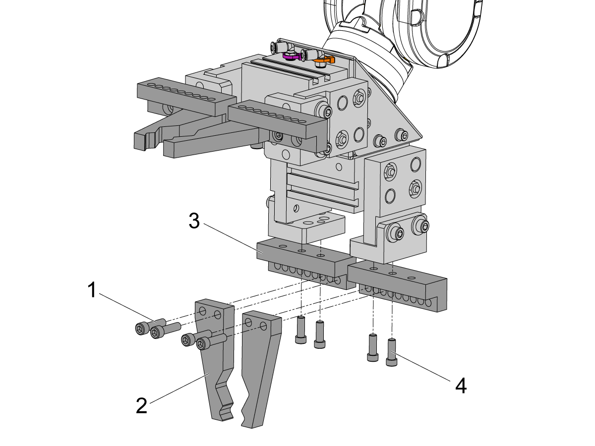
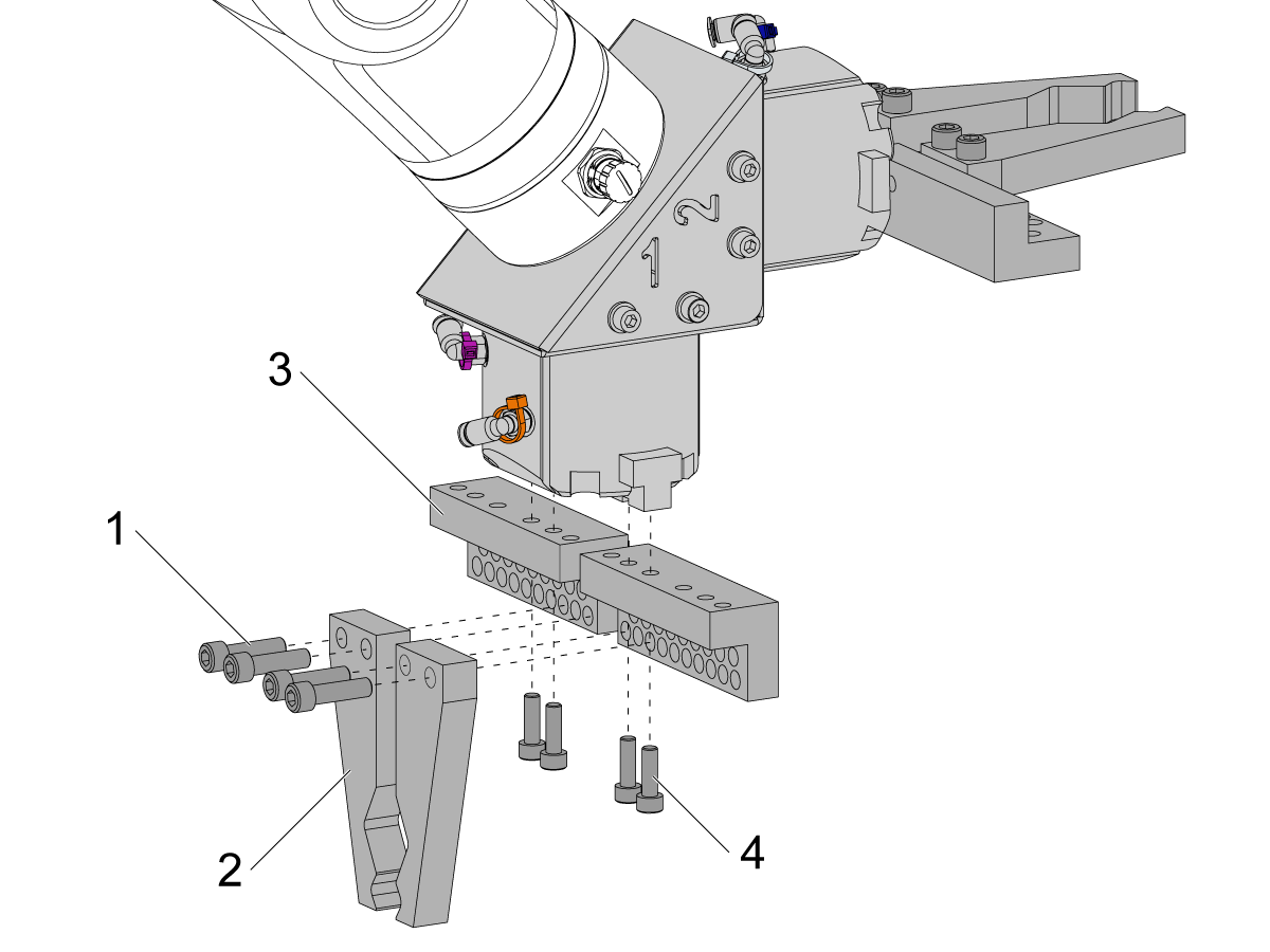
    Asenna tangon tarttujan sormet poistamalla löysät tarttujan levyt tarttujien rungoista.

    Asenna tangon tarttujapulttilevyt [3] (x8) SHCS M6 -ruuveilla [4]. Kiristä 10 ft-lb:n kireyteen.

    Asenna tangon tarttujan sormet [2] (x8) kuusiokantaruuveilla 1/4-20 [1]. Kiristä 13 ft-lb:n kireyteen.

    5

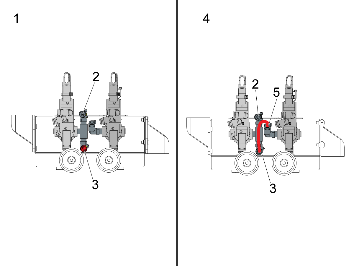
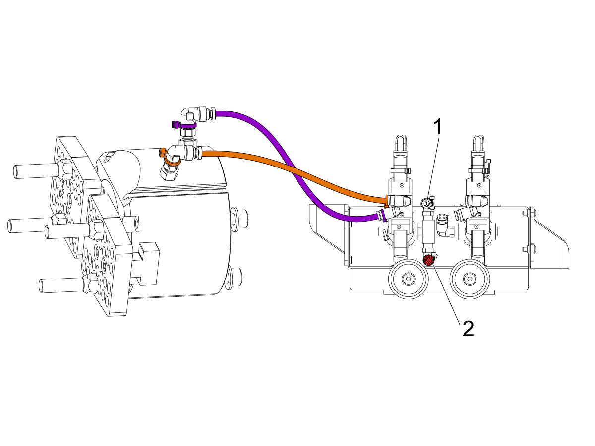
    Määritä pneumaattisissa tarttujissa käytettävä kaksoispaineilmasolenoidikokoonpano sen mukaan, onko kyseessä yhden [1] vai kahden [2] tarttujan kokoonpano. 

    Jos käytössä on yksi tarttuja [1], liitä tuleva ilma liittimeen [2] ja pidä tulppa liittimen [3] toisessa päässä kuvan mukaisesti.

    Jos käytössä on kaksi tarttujaa [4], irrota liittimen [3] tulppa ja kiinnitä pieni paineilmaletku toiseen solenoidiin [5]. Liitä sitten tuleva paineilmaletku liittimeen [2] niin, että molemmat solenoidit vastaanottavat ilmaa.

    6

    Yksittäistarttuja:

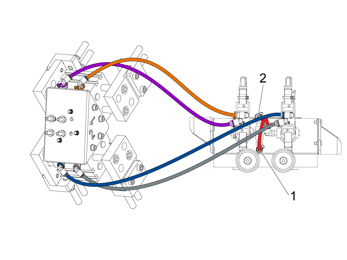
    Reititä (x2) paineilmalinjat tarttujasta samaan värikoodattuun liittimeen kaksoisilmasolenoidikokoonpanossa. 

    Kiinnitä paineilmalinjat kietomalla ne kaapelikanavaan. Kiinnitä kaapelikanava cobotiin tarranauhalla. Varmista, että kaapeleissa on riittävästi löysyyttä, jotta ne eivät rasitu, kun cobot on täysin ulkona.

    Aseta paineilmaletku käytetyn solenoidin liittimeen [1]. 

    Varmista, että tulppa on asennettu käyttämättömän solenoidin liittimeen [2]. 

    7

    Kaksoistarttuja:

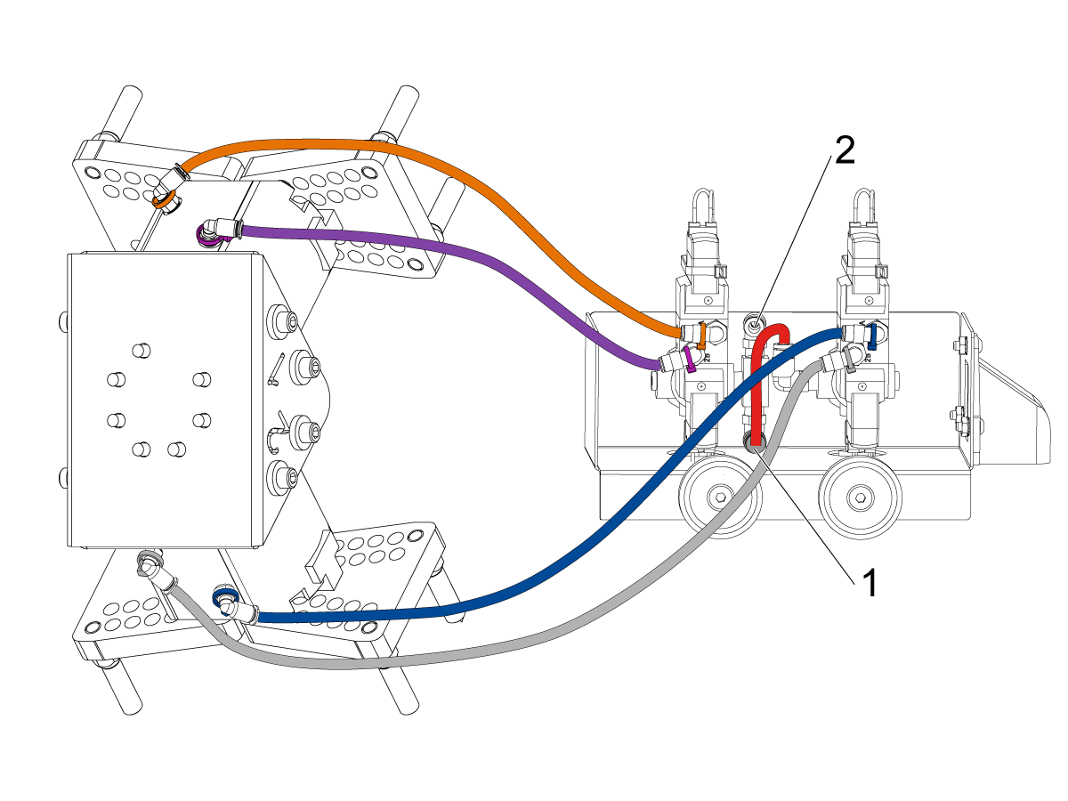
    Reititä (x2) paineilmalinjat tarttujasta nro 1 samaan värikoodattuun liittimeen kaksoisilmasolenoidikokoonpanossa. 

    Reititä (x2) paineilmalinjat tarttujasta nro 2 samaan värikoodattuun liittimeen kaksoisilmasolenoidikokoonpanossa. 

    Kiinnitä paineilmalinjat kietomalla ne kaapelikanavaan. Kiinnitä kaapelikanava cobotiin tarranauhalla. Varmista, että kaapeleissa on riittävästi löysyyttä, jotta ne eivät rasitu, kun cobot on täysin ulkona.

    Aseta lyhyt paineilmalinja [1], joka yhdistää ensimmäisen solenoidin toiseen. 

    Aseta tuloilman paineilmaletku liittimeen [2]. 

    Parts Table Assembly

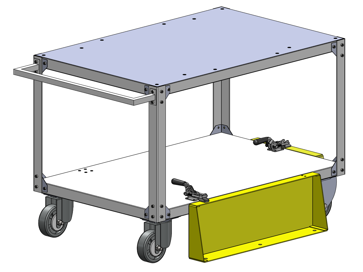
    Jos osapöytä on tilattu, noudata alla olevia asennusohjeita:

    Haas-robotti – Osapöytäkokoonpano

    HUOMAUTUS: Jos HC10-KONEVALMIS PAKKAUS ostettiin, pyöriä ei tarvitse asentaa, jos osapöytä asennetaan suoraan puiseen kuormalavaan.  

    Verification

    Hätäpysäytyksen testaus:

    • Paina jokaista Haas ohjaustaulun, RJH-XL:ssä ja Cobotin ohjaustaulussa olevaa HÄTÄ-SEIS-painiketta (E-STOP). Varmista, että kone tuottaa 107 HÄTÄPYSÄYTYS -hälytyksen (EMERGENCY STOP).  Jos HÄTÄPYSÄYTYS-painike ei anna 107 HÄTÄPYSÄYTYS -hälytystä, tarkista johdotus. Lataa uusimmat konfiguraatiotiedostot ottaaksesi RJH-XL:n käyttöön.

    Testaa robotin turvalaite:

    Varmista, että Haasin ohjaustaulu on HÄTÄ-SEIS-painikkeella tai valoverholla laukaistava kuvake, kun robotin turvalaite laukeaa. 

    • Aita – Aseta avain lukitukseen ja varmista, että lukituksen edessä olevat kaksi punaista LED-valoa ovat POIS PÄÄLTÄ. Irrota avain lukituksesta ja varmista, että kaksi punaista LED-valoa ovat PÄÄLLÄ. 
    • Alueskanneri – Astu suojakentän sisälle ja varmista, että alueskannerin punainen LED-valo syttyy. Siirry suojakentän ulkopuolelle ja varmista, että vihreä LED-valo syttyy.
    • Valoverho – Häiritse valoverhon säteitä ja varmista, että valoverholla käynnistettävä kuvake näkyy Haas-ohjaustaulussa. Paina [CHIP FWD]. Astu valoverhon palkkien ulkopuolelle ja varmista, ettei Haas-ohjaustaulussa näy kuvakkeita. 

    HUOM: Jos valoverhon laukaisema kuvake ei tule näkyviin, tarkista johdotus, suuntaus ja että tehdasasetus: 2191 [694:] VALOVERHON TYYPPI on asetettu arvoon LC_TYPE_1.


    Testaa tarttujien toiminta:

    • Varmista, että molemmat tarttujat lukittuvat ja avautuvat oikein.
    • Paina  [CURRENT COMMANDS]  ja siirry  Devices > Robot > Jogging -välilehdelle.
    • Paina [F2] viimeistelytarttujan lukitsemiseksi/avaamiseksi.
    • Paina [F3]  kiinnittääksesi/vapauttaaksesi  raakatarttujan.

    Testaa kauko-ohjain.

    • Poista kauko-ohjain telineestä
    • Paina  [HANDLE JOG]  piniketta. 
    • Paina  [CURRENT COMMANDS]  ja siirry  Devices > Robot > Jogging -välilehdelle.
    • Paina kauko-ohjaimen Joint-painiketta nivelkoordinaatteihin siirtymiseksi.
    • Siirrä robotti turvalliseen paikkaan.

    TÄRKEÄÄ: Jos näkyviin tulee keltainen varoitusilmoitus ”Ota valoverho tai kennon turvalaite käyttöön” robotin työnhaun aikana, varmista, että turvaparametria käytettiin lataamalla määritystiedostot uudelleen HBC:stä. 

    Turva-/käyttötilan käytön varmistaminen

    Kaikki Haasin CNC-jyrsinkoneet on varustettu ohjauspaneelin sivussa olevalla avainkytkimellä, jonka avulla asetustapa voidaan lukita ja vapauttaa. Robotilla on seuraavat toiminnot valitun tilan mukaan. 

    • Kun Haas-ohjaus on suoritustavalla, tila 1, robotin turvalaitteen liipaisu pysäyttää kaiken liikkeen. Tätä liikettä ei voi käynnistää, ennen kuin robotin turvalaite ei enää käynnisty.
    • Kun Haas-ohjaus on asetustilassa (tila 2), rajallisen nopeuden liikkeitä, kuten robotin akselin nykäyssyöttöä, voidaan suorittaa robotin liikeradan ja poiminta-aseman ohjelmoimiseksi, robotin työkalun keskipisteen (korjain) määrittämiseksi ja osien lataamiseksi ja poimimiseksi karasta tai koneen osapidikkeestä tms. Ohjelmoitua reittiä voidaan myös käyttää hitaasti robotin ohjelmoidun reitin osoittamiseksi. Asetustilassa olevaa robottia voidaan käyttää nykäyssyötöllä vain, kun F2-painiketta RJH painetaan.

    Haas Robot - Quick Start Guide

    Kun olet asentanut robotin, määritä työ alla olevien ohjeiden mukaisesti.

    Haas-robotti – Pikaopas

    Disable the Robot

    Robotin kytkeminen pois päältä koneen käyttämiseksi itsenäisessä tilassa. Paina [SETTING]. Muuta seuraavia asetuksia: 

    • 372 Kappaleen lataajan tyyppi arvoon 0: Ei ole
    • 376 Light Curtain Enabled  arvoksi  Off

    5.2 Sorvin asennus

    Recently Updated

    Haas Cobot 10 (HC10) – Sorvi – Asennus


    AD0715

    Versio G – 7/2026

    Introduction

    Nämä ohjeet näyttävät, miten Haas-kobottivarsipaketti 10 kg asennetaan (HC10). 

    Huomautus: Haasin suunnittelema työsolu, joka koostuu CNC-koneesta ja robotista, on arvioitu CE-vaatimusten mukaiseksi. Muutokset Haasin solurakenteeseen on arvioitava sovellettavien standardien mukaisuuden osalta, ja ne ovat käyttäjän/integraattorin vastuulla.

    Koneen vaatimukset:

    • Versio 100.24.000.1001 tai uudempi
    • HR5.51H.16.beta.20231213.zip-versio tai HR6.4.9.tmp20240919.zip-versio.
    •   
    • ST-10/15/20/25/28 ja DS-20Y/25Y Uudelleenkäynnistettävä, metallilevy (sileä pinta)
    • Haasin  automaattisyöttö
    • I/O-piirilevy 34-349xB tai uudempi
    • 93-1000610 KAUKO-OHJAIMEN LCD-KOSKETUSNÄYTTÖ (RJH-XL)KAUKO-OHJAIN – XL  

     HUOM: Jos koneeseen on asennettu kappaleen noukkija. Poiminta-alusta on robotin tiellä ja se on poistettava. Aukon peittämiseen ja sulkemiseen on valmistettava yksilöllinen metallilevypaneeli.

    Työkaluvaatimukset:

    • Talttapäinen miniruuvimeisseli

    Fixing / Anchoring Requirements

    • The Haas 10KG Cobot (HC10) is configured and sold by Haas with a pedestal/table that is sufficiently stable when used according to Haas defined part size and weight limits. 
    IMPORTANT:  For more information directly on the Hans Cobot, refer to the Hans Robot Operation Manual for Elfin Software.

    There are 3 scenarios in which the cobot option can be installed on a Haas machine:

    1. Cobot option was ordered at the same time as the machine. Both the cobot and the machine are being installed together.
    2. Cobot option is ordered so that it can be installed on a previously installed machine.
    3. Cobot option was previously installed on a machine, but will now be moved to a different Haas machine.

    In scenarios 2 and 3, additional parts will need to be ordered under the Serial Number of the Haas machine. See the tables below for what parts are needed in the different scenarios.

    Scenario 1 - Cobot and Machine are ordered and installed together

    Component Part Number Description
    NO ADDITIONAL PARTS NEED TO BE ORDERED WHEN COBOT AND MACHINE ARE ORDERED TOGETHER

    Scenario 2 - Cobot being field installed on existing Haas Machine

    Component Part Number Description
    CHECK TO SEE IF HAAS MACHINE ALREADY HAS THESE FEATURES & PARAMETERS BEFORE ORDERING
    Robot Feature Unlock Parameter 93-1001031 Kit activates the robot feature on the Haas machine. To check if you need this kit, go to the Features tab on the Haas Control and check if the Robot option is highlighted. This kit does not include any physical parts.
    Load Type Safety Parameters 93-1000997 Front Automation Safety Parameters - Kit is needed when the cobot will be loading parts through the front door of the Haas machine. This kit does not include any physical parts and the autodoor option would need to be purchased and installed separately.
    OR  
    93-1000996 Side Automation Safetly Parameters - Kit is needed when the cobot will be loading parts through the side window of the Haas machine. This kit does not include any physical parts and the autowindow option would need to be purchased and installed separately.

    Scenario 3 - Cobot is being transferred from one machine to a different Haas Machine

    Component Part Number Description
    Cobot Integration Kit See Integration Kit Compatibility Chart Kit is needed to install parts on the Haas machine to interface with the cobot. This includes the interface box, door switches, etc... as well as the Robot Unlock Feature parameter. This kit only needs to be purchased when transferring a cobot to a new Haas machine since these parts are normally included when a cobot is ordered. 
    Load Type Safety Parameters 93-1000997 Front Automation Safety Parameters - Kit is needed when the cobot will be loading parts through the front door of the Haas machine. This kit does not include any physical parts and the autodoor option would need to be purchased and installed separately.
    OR  
    93-1000996 Side Automation Safetly Parameters - Kit is needed when the cobot will be loading parts through the side window of the Haas machine. This kit does not include any physical parts and the autowindow option would need to be purchased and installed separately.
    Safety Device 08-1899 Multi-Sided Light Curtain Kit - Kit is needed if the safety device is NOT going to be transferred from the first machine and the second Haas machine needs it's own safety device. This kit makes a 4-sided protective barrier.
    OR  
    08-1948 5-Sided Light Curtain Kit - Kit is needed when the safety device is NOT going to be transferred from the first machine machine and the second Haas machine needs it's own safety device. This kit makes a 5-sided protective barrier.
    OR  
    08-1987 Laser Area Scanner Kit - Kit is needed when the safety device is NOT going to be transferred from the first machine machine and the second Haas machine needs it's own safety device. This area scanner has a sensing distance of 4meters.

    Lathe Setup

    1

    SULJE virta konesta.

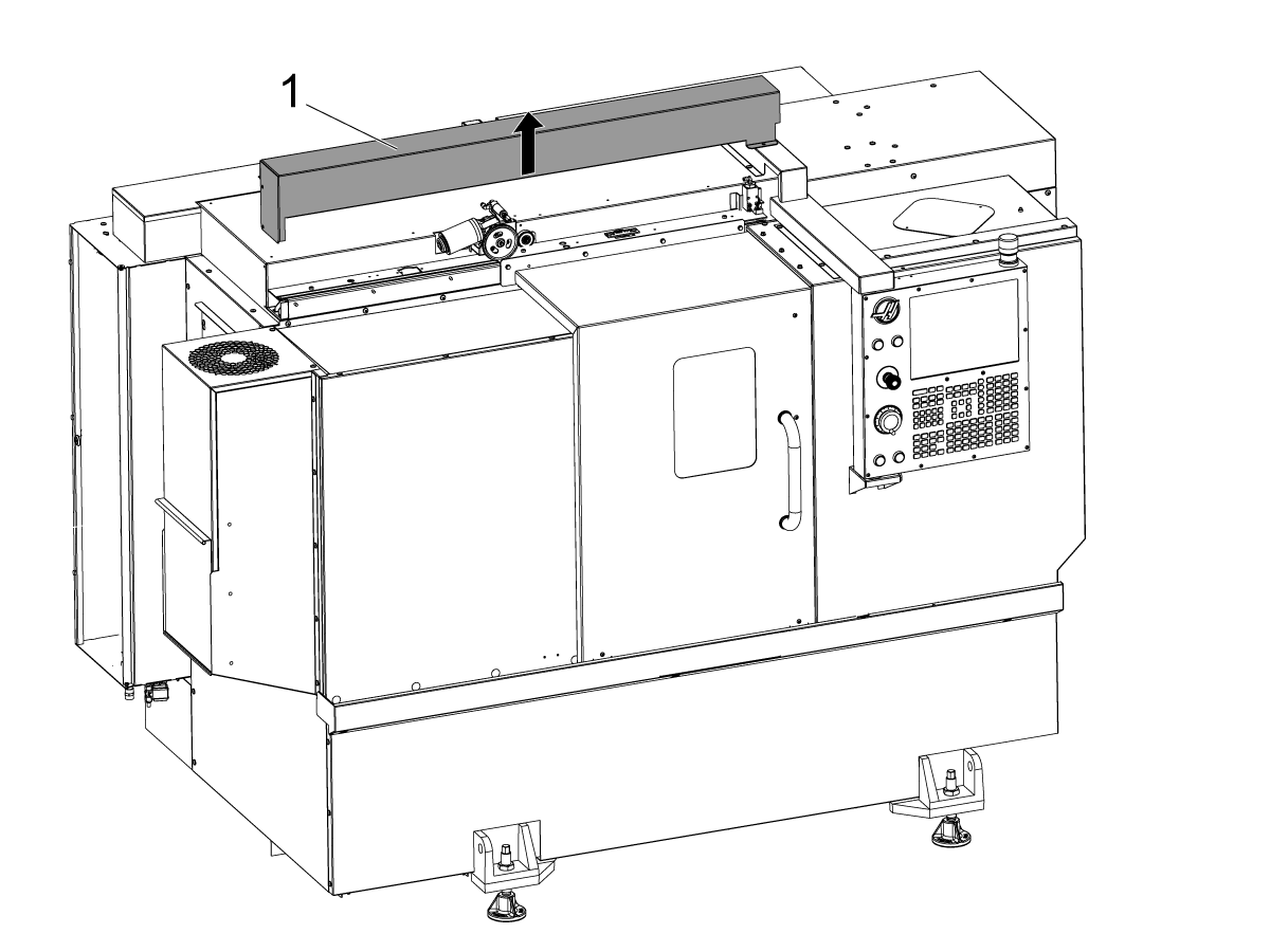
    Poista automaattioven suojus [1].

    2

    ST-20/25 ja DS-20Y/25Y:

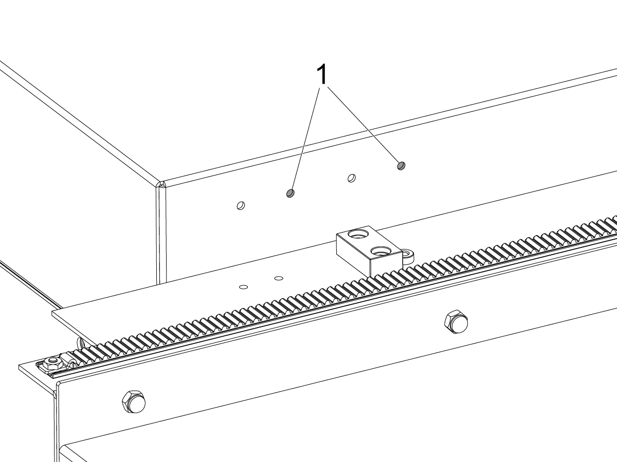
    Koneet, joissa on kattopaneelin kytkimen kannattimen reiät. Asenna kytkimen kannatin oikeanpuoleisiin reikiin[1] tuotteelle ST-20/25.

    3

    Koneet, joissa ei ole kattopaneelin kytkimen kannattimen reikiä.

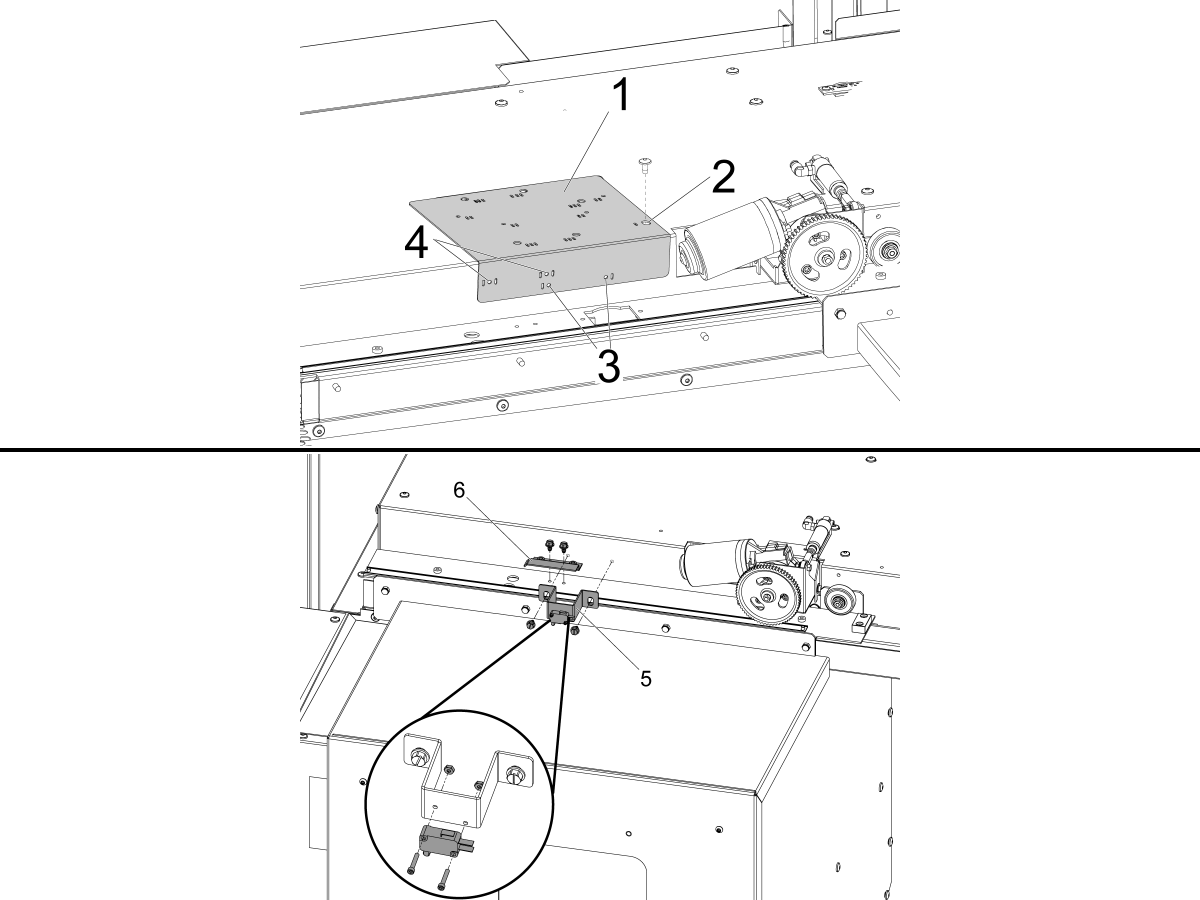
    Käytä annettua porasapluunaa [1] ja poraa DOOR FULLY OPEN tilakytkimen kiinnitysreiät.

    Kohdista oikeanpuoleisin reikä porasapluunan yhdellä lovella merkityn reiän [2] päälle siten, että automaattioven kiinnitysreikä on automaattioven moottorin vasemmalla puolella ja kiinnitä se BHCS-ruuveilla.

    ST-10/15:

    • Poraa kaksi Ø 3/16":n (4,7 mm) kiinnitysreikää porasapluunan yhdellä lovella merkittyjen aukkojen [3] läpi.

    ST-20/25 ja DS-20Y/25Y:

    • Poraa kaksi Ø 3/16":n (4,7 mm) kiinnitysreikää porasapluunan molemminpuolisilla lovilla merkittyjen kahden aukon [4] läpi.

    Asenna DOOR FULLY OPEN -kytkinyksikkö [5] ja DOOR FULLY OPEN -kytkentämerkki [6] toimitetuilla itseporautuvilla ruuveilla.

    4

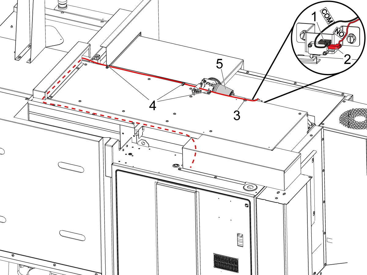
    Liitä DOOR FULLY OPEN -kytkin merkintöjen mukaisesti:

    • BLK <COM> yläliittimeen [1].
    • RED <NO> keskiliittimeen [2].

    Vedä kaapeli ohjauskaappiin kuvan osoittamalla tavalla.

    HUOMAUTUS: Varmista, että asennat sarjaan kuuluvan magneettikiinnikkeen [3] ja kaapelipuristimet [4], jotta kaapeli ei osu liikkuvaan automaattioven moottoriin [5].

    5

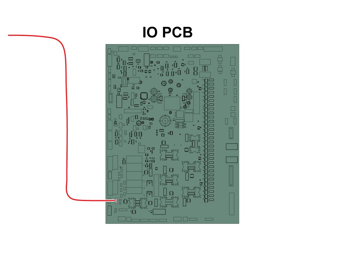
    Liitä kaapelin toinen pää SIO P27 RRI Ovi auki -tuloon. 

    HUOMAUTUS: Varmista, että koneen virta on POIS PÄÄLTÄ.

    Asenna automaattioven kansi.

    6

    • Jousityöntäjässä on varsi, joka sopii joko 25 mm tai 1” työkalunpitimeen
    • Tämän työkalun on nostettava revolverin työkalunpidin
    • Jos kone on mallia ST-10/15, tarvitset kaksi tyhjää työkalunpidintä, jotka mahdollistavat tarpeeksi tilaa tarttujalle
    • Ohjelmoi seuraavat vaiheet kaikkien ohjelmien alkuun varmistaaksesi, että kappale on kunnolla kiinni istukassa:
      • Etsi kappaleen etuosan jousityöntäjä
      • Siirrä Z-akselia puristaaksesi jousta noin 0,50 tuumaa tai 12,7 mm
      • Avaa istukka yhden sekunnin viiveellä
      • Sulje istukka yhden sekunnin viiveellä
      • Peräytä revolveri mahdollisimman turvalliseen asentoon

    Huomautus: Jousityöntäjän osanumero on: 

    • 30-12642 JOUSITYÖNTÄJÄ 25 mm:n tai 1,0 tuuman pidike myydään erikseen. 

    Cobot Installation

    1

    Varmista, että Cobot ja sen ohjausruutu ovat samasta yhteensopivasta sarjasta vastaavilla sarjanumeroilla. 

    Haas sarjanumerolla [1] on valkoinen tarra. Varmista, että nämä ovat samat molemmissa rasioissa.

    Laitteessa on keltainen ympyrätarra, jonka tunnistenumero on [2]. Varmista, että nämä ovat samat molemmissa rasioissa.

    2

    Mittaa tämä mitta koneen alareunasta pöydän sivupaneeleihin.

     Huomautus: Seuraavat mitat ovat suositeltuja etäisyyksiä. Sijainti voi vaihdella käyttäjän sovelluksen mukaan. 

    Käytä seuraavien vaiheiden mittoja viitteenä etu- ja sivulatauksiin käytettäville coboteille. 

    Haas Cobot 10:n pariliittämistä Haas Cobotin jalustaan suositellaan.  Jalusta on riittävän vakaa Haasin määrittelemien osakoko- ja painorajojen mukaisesti käytettäessä. 

    3

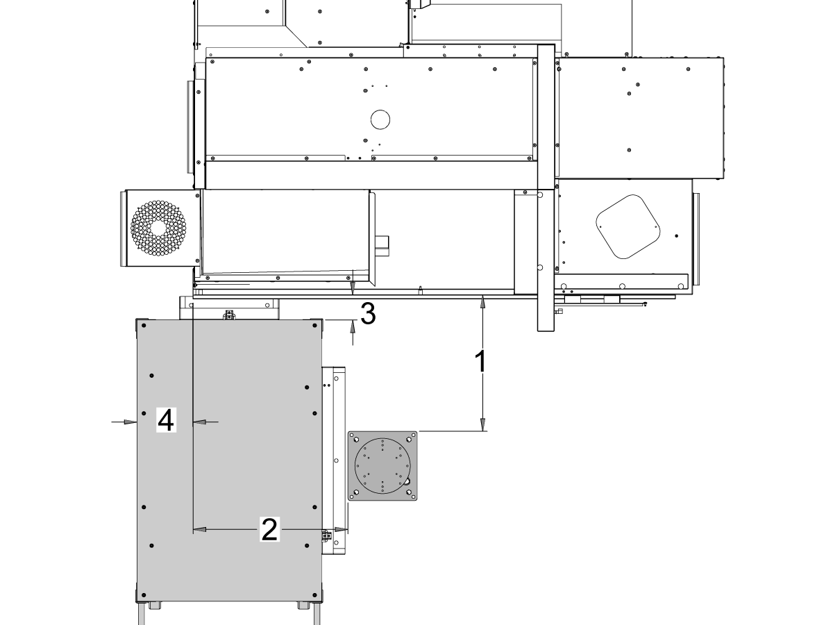
    ST-10- ja ST-15-koneet:

    Sijoita jalusta ja osapöytä seuraavaan paikkaan koneeseen nähden:

    24,5 in
    Mitat Brittiläinen mittajärjestelmä (tuumaa) Metrijärjestelmä (cm)
    Koneen etuosasta jalustan etupuolelle [1] 62,2 cm
    Koneen vasemmalta puolelta jalustan vasemmalle puolelle [2] 26,25 in 66,7 cm
    koneen etuosasta osapöydän etupuolelle [4] 5,5″ 14 cm
    Koneen vasemmalta puolelta osataulukon vasemmalle puolelle [4] 9,75 in 24,7 cm

    4

    Updated

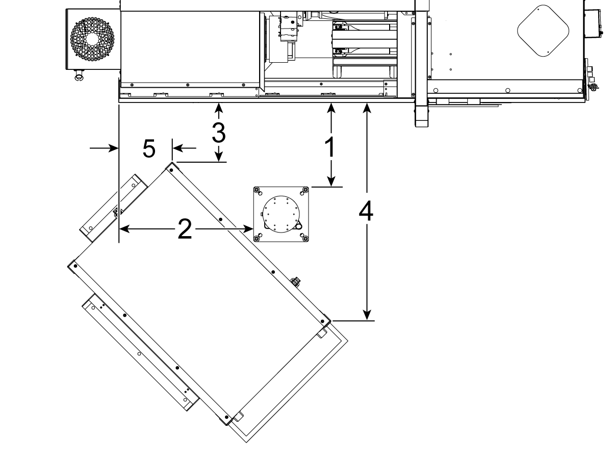
    ST-20- ja ST-25-koneet ja DS-20Y/25Y:

    Sijoita jalusta ja osapöytä seuraavaan paikkaan koneeseen nähden:

    Mitat Brittiläinen mittajärjestelmä (tuumaa) Metrijärjestelmä (cm)
    Koneen etuosasta jalustan etupuolelle [1] 19,5 in 49,5 cm
    Koneen vasemmalta puolelta jalustan vasemmalle puolelle [2] 28,5 in 72,4 cm
    Koneen etuosasta osapöydän vasempaan etukulmaan [3] 14,5" 36,8 cm
    Koneen etuosasta osapöydän oikeaan etukulmaan [4] 71 in 180 cm
    Koneen vasemmasta puolesta kappalepöydän vasempaan etukulmaan[5] 10,75 in 27,3 cm

    5

    ST-30/35- ja DS-30Y-koneet:

    Sijoita jalusta, osapöytä ja Cobotin ohjausrasia[5] seuraavaan paikkaan koneeseen nähden:

    Mitat Brittiläinen mittajärjestelmä (tuumaa) Metrijärjestelmä (cm)
    Koneen etuosasta jalustan etupuolelle [1] 8,5″ 21,6 cm
    Koneen vasemmalta puolelta jalustan vasemmalle puolelle [2] 42″ 106,7 cm
    Koneen vasemmalta puolelta osapöydän vasemmalle puolelle [3] 23,5 in 59,7 cm
    koneen etuosasta osapöydän etupuolelle [4] 24,0 in 61,0 cm

    6

    Kiinnitä jalusta maahan. Tasaa pöytä vatupassin avulla.

     HUOMAUTUS: Säädettävää jalustaa varten aseta haluttu korkeus löysäämällä asetusruuveja [1] ja säätämällä sitten haarukkatappia [2]. Kiristä pidätinruuvit [1] uudelleen ennen robotin asentamista. Aseta vatupassi jalustan päälle käyttäen (x4) kuusiopultteja alustassa X- ja Y-tasojen tason asettamiseen.

    Aseta Cobot-ohjausrasia [3] suoraan jalustan viereen, jotta varmistetaan kaapelien riittävä löysyys.  

    7

    Poista robotti kuljetuslaatikosta. 

     HUOMAUTUS: Asenna adapterilevy tarvittaessa jalustan ja robotin väliin. 

    Asenna Cobot jalustan päälle.

     HUOMAUTUS: Varmista, että cobot-kaapelin liitin [1] on suorassa koneen etuosan kanssa. 

    TÄRKEÄÄ:  Cobot painaa noin 40 lbs ja on nostettava laitteella, jolla voi turvallisesti nostaa kyseisen painon.

    Poista robotin nostokiinnikkeet ja -osat robotin asentamisen jälkeen.

    8

    Cobot-pakkauksen sisällä on pieni pussi [1], joka on täynnä varaosia, mukaan lukien: 

    • Sulake
    • Ruuvit (x2)
    • Ohjausrasian avaimet

    Keskikokoinen pussi [2] on täytetty ylimääräisellä M12-liittimellä. Tätä kaapelia voidaan käyttää pääty-I/O-moduulin tulojen ja lähtöjen määrittämiseen. 

    Suurikokoinen pussi [3] on täynnä papereita ja siinä on USB-muistitikku, jossa on ladattu Cobot-ohjelmisto.

    Varmista, että pidät nämä varaosat turvallisessa paikassa tulevaa käyttöä varten. 

    Robot Electrical & Air - Installation

     DANGER: Working with the electrical services required for CNC machines is extremely hazardous and can result in serious injury or death.

    Before connecting line wires to the CNC:

    • Turn off all power to the machine at the source.
    • Perform a Lockout-Tagout (LOTO) procedure to ensure the power remains off during service.
    • Verify that power has been disconnected by using an AC voltage detector on all incoming lines.

    If you are uncertain about how to safely disconnect power or perform LOTO procedures:

    • Do not proceed.
    • Contact qualified personnel or obtain appropriate assistance before continuing.

    Failure to follow these precautions may result in electrical shock, equipment damage, or fatal injury.

     Danger: Before beginning any work inside the control cabinet, verify that the High Voltage indicator light on the 320V Power Supply / Vector Drive has been off for a minimum of five (5) minutes. This waiting period ensures that residual voltage has dissipated and reduces the risk of electric shock.

    Certain service procedures involve high-risk electrical components and may pose serious injury or fatality hazards. Technicians must not attempt any procedure unless they have a complete understanding of the steps involved and the associated risks.

    If there is any uncertainty regarding a procedure, contact your Haas Factory Outlet (HFO) to arrange for a qualified service technician.

    1

    Connect Interface Box to Haas Machine:

    The robot safety devices interface box 32-9018 has magnetic mounts to attach to the machine sheet metal. Mount the interface box [1] as shown in the picture.

    Route the interface electrical cables [2] along the enclosure with the magnetic mounts and zipties. Route the cable through the bottom of the electrical cabinet.

    NOTE: For information on upgrading the interface box to the Robot Safety Devices Interface Box, refer to the Robot Safety Devices Interface Box - Installation - AD0703. 

    2

    Connect Interface Box to Haas Control Cabinet:

    Connect cable 33-8562C E-STOP terminal block to TB-1B [1] and connect the Setup mode terminal block to TB-3B [1] on the SIO PCB.  

    Plug the user relay into K9 and K10 [2].

    Verify the jumper is installed on the SIO PCB at JP1.

    Connect the pigtail cable labeled P1 SIO to the SIO PCB at P1 [3]

    NOTE: If the machine has a Regen Vector Drive, unplug cable 33-0634 FILTER OV TO IOPCB P1 from P1 SIO and plug it into the connector FILTER OV FAULT on cable 33-8562C. If the machine does not have a Regen Vector Drive, do not plug anything into the connector FILTER OV FAULT.

    Connect the RJ-45 cable [4] to Ethernet to USB adapter [5] (33-0636).  Connect the USB connector end to the Maincon PCB J8 top port. Add a ferrite filter [6] to the USB adapter.

    Mount the 24VDC Power Supply [7] to the left side of the control cabinet and plug into connector labeled 24V PS on cable 33-8562C. Connect cable 33-1281 [8] to the 24VDC Power Supply [7] and plug into P3 on the PSUP PCB. 

    3

    For MM/SMM CM/CL machines Without XMR

    If P3 is occupied by a jumper connected from P3 [10] to P7 [9] on the PSUP PCB, a splitter cable is needed to allow the 24VDC power supply [7] to be connected to the 120VAC connectors on the PSUP. Connect the male connector of the splitter cable to P3 [10] and then connect the jumper from that cable to P7 [9] and also cable 33-1281 [8].

    Note: Make sure that the jumper cable is connected where the red lines up with the red from the splitter cable.

    4

    Inside the Cobot control box, install part of the robot signals cable (33-1272 or 33-1351).  To do so, remove the safety connector [1] from the Cobot control box in order to install the different colored wires into their respective location

    33-1272 / 33-1351 cables [2] going to safety connector:

    • Gray wire to top 24V
    • Red wire to bottom 24V
    • Green wire to EI0
    • Brown wire to EI1
    • Jumper [3] from SA0 to SA1
    • Jumper  [4] from SB0 to SB1

     NOTE: The rest of the wires from this cable are not used. Put some electrical tape on each wire lead and Ziptie the leftover unused wires. 

    5

    Important: After installing all the cables from the robot signal cable, make sure that the fuse [1] remains installed at all times to protect the Cobot control box.

    6

    Connect Cobot to the Interface Box:

    Connect the RJ45 ethernet cable [1] from the Cobot Control Box to the interface box. Add a ferrite filter [2] to the RJ-45 cable.

    Connect the robot signals cable [3] from the Cobot Control Box to the interface box. 

    Connect the 120 VAC Cobot Power Cable [4] to the external power source. 

    Connect the robot power cable [5] from the control box to the Cobot.

    Connect the teach pendant cable [6] from the control box to the teach pendant. 

    NOTE: For more information regarding interlock fence, area scanner or light curtain installation, refer to the Robot Safety Device section below.

    7

    Make sure the Remote Jog Handle is installed onto the machine.

    NOTE: For more information on the RJH-XL installation, refer to Remote Job Handle - Touch Large (RJH-XL) - Installation - AD0533. 

    8

    Steps 7 thru 10 are wiring and hose routing instructions for the pneumatic grippers. Refer to the grippers installation section lower on this page for the mechanical installation.

    Install the dual air solenoid assembly on to the side of the pedestal while giving the airlines enough slack. Make sure it's in a position where it will not be in the way. Route the airline [1] under the machine back towards the CALM cabinet as shown.

    9

    Inside the CALM cabinet, remove a plug from one of the CALM manifold ports and install the check valve [1] (58-1863) onto the port's fitting. Route the input airline [2] from the dual air solenoid assembly (from previous step) into the CALM cabinet and connect the airline to the check valve.

    Turn the machine air supply ON.

    10

    Make sure to power OFF the control box [1].

    Connect the solenoid cable from the dual air solenoid assembly [2] into the Digital Output on the Cobot control box [1]. Remove the connector from Cobot control box.

    11

    Connect the gripper solenoid power cable (33-1276 / 33-1341) to the Digital Output terminal inside the control box. Install the different colored wires into their respective location:

    • Black/white cable into 0V
    • Black cable into DO0
    • Orange/white cable into 0V
    • Orange cable into DO1
    • Red/white cable into 0V
    • Red cable into DO2
    • Brown/white cable into 0V
    • Brown cable into DO3

    Power ON the control box.

    Robot Safety Device

    TÄRKEÄÄ: ÄLÄ KÄYTÄ ROBOTTIA, ENNEN KUIN OLET MÄÄRITTÄNYT TURVALAITTEEN ASETUKSET JA TESTANNUT SEN TOIMINNAN.

    Valoverho:

    Cobot-laitteiden oletusturvalaitteeksi toimitetaan valoverhon lähetin ja vastaanotin. Noudata alla olevia valoverhon asennusohjeita: 

    Valoverhon asennus

    HUOMAUTUS: Jos on tilattu alueskanneri tai HC10-konevalmis sarja, käytössä on myös 1M-valoverhovastaanotin ja -lähetin. Nämä toimitetaan kaikkien Cobot-robottien mukana.

    Robottiaita:

    Jos kone on varustettu aidalla, robottiaita ja oven lukituskokoonpano on asennettava koneeseen. Noudata alla olevia asennusohjeita:

    Robotin aidan asennus

    Kun aita on asennettu, asenna sen jälkeen aitapaneeli koneen ja robotin aidan väliin.

    Alueskanneri:

    Jos koneessa on alueskannerivaihtoehto, alueskanneri on asennettava ja määritettävä tilaan. Noudata alla olevia asennusohjeita: 

    Alueskannerin asennus

    First Power-UP

    1

    Power ON the Haas machine. 

    Power ON the Cobot by flipping the power switch [1].

    Power ON the Cobot teach pendant by pressing the circle [2]. 

    Make sure that E-STOP [3] on the Cobot teach pendant is released. 

    In order to change the language, click on the language drop down menu. Choose EN for English. To confirm this setting change, the Cobot teach pendant will have a popup asking to insert the username & password. 

    Enter "admin" for both the username and password. 

    2

    Note: The Cobot teach pendant will have a popup asking to insert the username & password. To sign into the teach pendant use these credentials:

    • Username = admin
    • Password = admin

    Go into Run mode. Press Enable. 

    Go into Jog mode [1].

    Move each joint to it's zero location with the Move Zero buttons [2]. 

    3

    Once the robot is in it's zero location, verify that the hash lines [1] align on either side of each joint on the Cobot. 

     IMPORTANT: If any joint hash lines [1] do not align, jog the specific joint accordingly until all the hash lines [1] do align. This position will be set in the next step as the new Cobot zero position.  

    Connect an ethernet cable [2] from the Cobot control box into a computer.

    On the computer, change the adapter setting to enable the ethernet port. 

    Note: See next steps for help on changing adapter settings.

    4

    To change the adapter settings, open the settings page [1] on the computer, then click on Network & Internet [2] which will bring up the network status page.

    Click on Change adapter options [3] then right click on Ethernet [4] and open up the properties window [5]. From there select the Internet Protocol Version 4 (TCP/IPv4) [6] option and click Ok. 


    5

    The ethernet settings will now be correct. Open a web browser window and type in the IP address of the Cobot[1]. 

    Note: This is the same process as connecting a laptop to an HRP-1/2/3. For more information on connecting to the Cobot via ethernet, refer to the video on the HRP-Troubleshooting page that is in the Connect & Jog Haas Robot section. 

    6

    Download HRTool through HBC. On the Service section of HBC, navigate to Utilities > Documents and Software > 01 Control Software > 01 Next Generation Control > 10 Cobot Software > HRTool.zip.

    Unzip the folder and navigate to HRToolsMaind.exe.

    Insert the Cobot IP address found under the Systems tab.  Click Set. 

    Go to the Config tab on HRTool.

    Click "get" to see the actual vs. theoretical encoder values. 

    Click "set" to set the theoretical to the actual encoder values. This step sets the Cobot's current position as it's new home position. 

    7

    Make sure that each joint's actual and theoretical encoder values match. 

    NOTE: If the valuyes do not match, press "Set" again. 

    8

    On the teach pendant, navigate to System [1] and then Update System. 

    Confirm the Cobot firmware [2] is either:

    • HR5.51H.16.beta.20231213.zip
    • HR6.4.9.tmp.20240919.zip

    NOTE: Firmware version HR6.4.9.tmp.20240919.zip is compatible with all size cobots.

    Refer to the Haas Cobot - Maintenance chapter for the firmware update procedure. 

    9

    Turn on the Haas CNC.

    Zero Return all Axes.

    Insert Service USB key.  Go into Service mode.

    Go to Parameters> Factory tab.  Change the following:

    • 1278 [1278:] Robot Ready E-Stop Enabled to TRUE
    • 2191 [694:] LIGHT CUTAIN TYPE to LC_TYPE_1
    • 2194 [:] Enable Front Door Fully Open Switch to TRUE

    Note: Machines with Software Version 100.20.000.1010 or higher will need to change the following parameter:

    • 2192 [:] Light Curtain Trigger Threshold to 0

    Press [SETTING].

    Set the Settings:

    • 372 Parts Loader Type to 3: Robot.
    • 376 Light Curtain Enabled to On


    10

    On the Haas pendant, press [CURRENT COMMANDS].

    Go to Devices>Robot>Jogging tab. Change the following:

    • Maximum Jogging Speed to 7.9 inch/sec

     Note: The jogging increments on the RJH are a percentage of this max speed value. In order to decrease the distance the robot travels of each jog wheel tick, you need to change your Maximum Jogging Speed to a lower value.

    Go to the Setup tab. Change the following:

    • Max Robot Speed to 118 in/sec (2000 mm/sec). 
    • Enter the Net Mass of the gripper. Refer to the layout drawings on our website (Single Gripper layout drawing OR Dual Gripper layout drawing) to get the correct value for this setting
    WARNING: Setting this value incorrectly can cause the Robot Arm to not move correctly. 
     
    • Number of Grippers to the number of grippers.
    • Raw Gripper Clamp Output to 1.
    • Raw Gripper Unclamp Output to 2.
    • Raw Gripper Clamp Delay to the clamp/unclamp duration in sec.
    • Raw Gripper Clamp Type to OD/ID.
    • Finish Gripper Clamp Output to 3.
    • Finish Gripper Unclamp Output to 4.
    • Finish Gripper Clamp Delay to the clamp/unclamp duration in sec.
    • Raw Gripper Clamp Type to OD/ID.

    Security Risk Level

    1

    IMPORTANT: Make sure to perform an appropriate risk-assessment and met all appropriate safety requirements. 

    2

    Based off the risk assessment, set the appropriate security risk level on the Cobot teach pendant. Navigate to Config > General Restrictions and tap of the desired security risk level [1] from 0 - 5.

    Use the  "admin" code in the safety verification to change the security level.

    NOTE: When the security risk level is lower, the robot will have a lower maximum speed, force, etc. When the security risk level is higher, the robot will have a higher maximum speed, force, etc. 

    This security risk level will calculate the maximum allowable force, speed, power, momentum, elbow speed and elbow force [2] that the Cobot will withstand before Alarm 9150.10017 Collison Stop Error is triggered. 

    IMPORTANT: The robot's programmed speed cannot be greater than the allowable speed from the security risk level. 

    NOTE: For more information regarding alarms, refer to the Haas Cobot - Troubleshooting Guide. 

    Activation

    1

    Download and load the configuration files by logging into the HAAS SERVICE PORTAL.

    Download the safety automation option front/side configuration files.

    Load the option configuration patch file to the control. Refer to the NEXT GENERATION CONTROL - CONFIGURATION FILE - DOWNLOAD/LOAD procedure.

    2

    Go to Parameters > Features > Robot to verify that the robot feature has appeared on the bottom.

    3

    Press [CURRENT COMMANDS].

    Go to Devices>Robot>Setup tab [1].

    Press [E-Stop].

    Press [F1] to connect the robot[2].

    The first time connecting a robot to a machine, the robot feature will need to be unlocked. This popup shows the machine's current software version, robot mac address and a generated code. Enter this information into HBC in order to receive the unlock code.

    4

    On HBC, go to the Service tab [1].

    On the left hand side of the screen, click on Activations [2], and then select Cobot Installation [3] to begin the process to the get the Cobot unlock code.

    The first step is to enter the Machine Serial Number [4] and the Cobot Serial Number [5] in the fields on HBC.

    Once you have entered the correct information, press Next [6] in the bottom right corner and continue through the steps until you receive the unlock code.

    Note: Make sure you are on the Cobot Installation tab [3] and not the Robot Installation tab. The Robot Installation is only used for the Haas Robot Packages. Using the Robot Installation for the Haas Cobots will result in an invalid unlock code.

    5

    Enter the Cobot's Haas Serial Number[1] and the unlock code to connect the robot to the machine. 

     Note: This step can only be completed by a HFO Service Technician.

     Note: The machine needs to be activated before the Cobot is activated. Follow the Machine Activation / Time Extension - NGC procedure.

    When the robot has connected with the machine, a yellow message saying Robot Activation Successful should appear at the bottom of the Haas screen.

    6

    Release the [E-STOP] and press RESET to clear the alarms. 

    Press the [HANDLE JOG] button. 

    Press the [CURRENT COMMANDS]  and go to Devices > Robot > Jogging tab.

     Note: The robot in setup mode can only be handle jogged while the F2 button the RJH is pressed. See Setup/Run mode section below.

    On the Remote Handle Jog Touch press the Joint button to go into the Joints Coordinates.

    Move the robot to an accessible location to install the grippers.

    Jog J6 to 0.0000 position. The location hole should be centered on top.

    Note: Press [E-STOP] before working on the robot.

    Gripper Installation

    1

    Turn off the machine air by turning the valve in the Air/Lube cabinet and pull the pressure relief valve to release the air in the system.

    2

    For the Dual Action Gripper:

    There are two versions of the dual-action grippers for this section, both of which have the same installation process.

    Jog the robot so that the location hole [1] is centered on top.

    Install the adapter plate [2] onto the end of the robot arm.

    Install the dual gripper assembly [3] onto the adapter plate [2].

    NOTE: Make sure to install Gripper 1 (which has the orange and purple zip ties) onto the Gripper 1 adapter plate section. 

    3

    For the Angled Single Action Gripper:

    Jog the robot so that the location hole [1] should be centered on top.

    Install the angle adapter plate [2] to the end of the robot arm.

    Install the single gripper assembly [3] onto the angle adapter plate [2]. 

    4

    To install the bar gripper fingers, remove the slug gripper plates from the gripper bodies.

    Install the Bar Gripper Bolt Plates [3] with (x8) SHCS M6 screws [4]. Torque to 10 ft-lbs.

    Install the Bar Gripper Fingers [2] with (x8) SHCS 1/4-20 [1]. Torque to 13 ft-lbs.

    5

    Configure the dual air solenoid assembly used for pneumatic grippers depending on single [1] or dual [2] gripper configuration. 

    For single grippers [1], connect the incoming air to the to the fitting [2] and keep the plug in the other end of the fitting [3] as shown in the image.

    For dual grippers [4], remove the plug in the fitting [3] and attach a small air hose to the second solenoid [5]. Then connect the incoming air hose to the fitting [2] so that both solenoids are receiving air.

    6

    For the Single Gripper:

    Route the (x2) air lines from the gripper to the same color coded fitting on the dual air solenoid assembly. 

    Secure the air lines by wrapping them in cable conduit. Use the velcro straps to attach the cable conduit to the Cobot. Make sure there is enough slack so that cables aren't strained when Cobot is fully extended.

    Insert the input air hose to the used solenoid's fitting [1]. 

    Make sure the plug is installed onto the unused solenoid's fitting [2]. 

    7

    For the Dual Gripper:

    Route the (x2) air lines from gripper #1 to the same color coded fitting on the dual air solenoid assembly. 

    Route the (x2) air lines from gripper #2 to the same color coded fitting on the dual air solenoid assembly. 

    Secure the air lines by wrapping them in cable conduit. Use the velcro straps to attach the cable conduit to the Cobot. Make sure there is enough slack so that cables aren't strained when Cobot is fully extended.

    Insert the short airline [1] connecting the first solenoid with the second. 

    Insert the input air hose to the fitting [2]. 

    Parts Table Assembly

    If the parts table option was ordered, follow the procedure below for assembly instructions:

    Haas Robot - Parts Table Assembly

    NOTE: If HC10 MACHINE READY KIT was purchased, there is no need to install the wheels if mounting the parts table directly into the wooden pallet. 

    Verification

    Test the E-stop:

    • Press each E-STOP button located on the Haas Pendant, RJH-XL, and Cobot Teach Pendant. Make sure the machine generates 107 EMERGENCY STOP alarm.  If the E-STOP button does not generate a 107 EMERGENCY STOP alarm verify the wiring. Load the latest configuration files to enable the RJH-XL.

    Test the Robot Safety Device:

    Make sure that there is an E-STOP or light curtain triggered icon on the Haas pendant when the robot safety device is triggered. 

    • Fence - Insert the key into the interlock, verify that the two red LED lights in the front of the interlock are OFF. Remove the key from the interlock, verify that the two red LED lights are ON. 
    • Area Scanner - Step inside the protective field, verify that the red LED lights up on the area scanner. Step outside the protective field, verify that the green LED lights up.
    • Light Curtain - Interfere the light curtain beams, verify that the light curtain triggered icon appears on the Haas pendant. Press [RESET]. Step outside of the light curtain beams, verify no icon appears on the Haas pendant. 

    NOTE: If the light curtain triggered icon does not show, verify wiring, alignment and factory setting: 2191 [694:] LIGHT CURTAIN TYPE is set to LC_TYPE_1.

    Test the Operation of the Grippers:

    • Verify that both grippers clamp and unclamp correctly.
    • Press the [CURRENT COMMANDS]  and go to Devices > Robot > Jogging tab.
    • Press [F2] to clamp/unclamp the Finish Gripper.
    • Press [F3] to clamp/unclamp the Raw Gripper.

    Test the Remote Jog Handle:

    • Undock the Remote Jog Handle
    • Press the [HANDLE JOG] button. 
    • Press the [CURRENT COMMANDS]  and go to Devices > Robot > Jogging tab.
    • On the Remote Handle Jog press the Joint button to go into the Joints Coordinates.
    • Move the robot to a safe location.

    IMPORTANT: If a yellow warning message appears saying "Please activate Light Curtain or Cell Safe" while trying to job the robot, verify the safety parameter was applied by re-uploading the configuration files from HBC. 

    Verify Safe / Run Mode Operation

    All Haas CNC machines are equipped with a key switch on the side of the control pendant to lock and unlock setup mode. The robot will have the following behaviors depending on what mode is selected. 

    • When the Haas control is in Run mode, mode 1, triggering the robot safety device stops all motion. This motion can not be started until the robot safety device is no longer triggered.
    • When the Haas control is in Set up mode, mode 2, speed limited motion such as jogging an axis of the robot can be performed in order to program a robot's path of motion, pick up position, set a robot's tool center point, (an offset), load and pick up parts from the spindle or part holder in the machine, etc. The programmed path will also be able to be run slowly to prove out the programmed path of the robot. The robot in setup mode can only be handle jogged while the F2 button the RJH is pressed.

    Haas Robot - Quick Start Guide

    Kun olet asentanut robotin, määritä työ alla olevien ohjeiden mukaisesti.

    Haas-robotti – Pikaopas

    Disable the Robot

    Robotin kytkeminen pois päältä koneen käyttämiseksi itsenäisessä tilassa. Paina [SETTING]. Muuta seuraavia asetuksia:

    • 372 Kappaleen lataajan tyyppi arvoon 0: Ei ole
    • 376 Valoverho käytössä arvoon Off


    5.3 DM/DT/MM/DC-1/UMC-350-asennus

    Recently Updated

    Haas Cobot 10 (HC10) – DM/DT/MM/DC-1/UMC-350 – Asennus


    AD0716

    Versio D – 11/2025

    Introduction

    Updated

    Nämä ohjeet näyttävät, miten Haas-kobottivarsipaketti 10 kg asennetaan (HC10).

    Huomautus: Haasin suunnittelema työsolu, joka koostuu CNC-koneesta ja robotista, on arvioitu CE-vaatimusten mukaiseksi. Muutokset Haasin solurakenteeseen on arvioitava sovellettavien standardien mukaisuuden osalta, ja ne ovat käyttäjän/integraattorin vastuulla.

    Koneen vaatimukset:

      Versio 
    • 100.24.000.1001 tai uudempi
    • HR5.51H.16.beta.20231213.zip-versio tai HR6.4.9.tmp20240919.zip-versio
    • DT/DM/MM/SMM/DC-1/UMC-350 Valmistettu ennen seuraavaa päivämäärää: (katso koneen vaatimukset jommastakummasta toimintaohjeesta)
      • Haasin automaattiluukku
      • Haasin automaatti-ikkuna
        Huomautus:MMM/SMM, DM-3, DT-3 ja DC-1 ovat käytettävissä vain sivulatausvaihtoehdossa(93-1001053).
      • Huomautus: MM/SMM-koneet, joissa ei ole muuntajaa, vaativat jakajakaapelin, joka on tilattava jälkiasennettaviin cobot-koneisiin. Jakokaapeli voidaan tilata mallina 93-5067.
    • I/O-piirilevy 34-349xB tai uudempi
    • 93-1000610 KAUKO-OHJAIMEN NYKÄYSSYÖTÖN KÄSIPYÖRÄN KOSKETUSNESTEKIDENÄYTTÖ (RJH-XL) KAUKO-OHJAIN – XL

    Työkaluvaatimukset:

    • Talttapäinen miniruuvimeisseli

    Fixing / Anchoring Requirements

    • The Haas 10KG Cobot (HC10) is configured and sold by Haas with a pedestal/table that is sufficiently stable when used according to Haas defined part size and weight limits. 
    IMPORTANT:  For more information directly on the Hans Cobot, refer to the Hans Robot Operation Manual for Elfin Software.

    There are 3 scenarios in which the cobot option can be installed on a Haas machine:

    1. Cobot option was ordered at the same time as the machine. Both the cobot and the machine are being installed together.
    2. Cobot option is ordered so that it can be installed on a previously installed machine.
    3. Cobot option was previously installed on a machine, but will now be moved to a different Haas machine.

    In scenarios 2 and 3, additional parts will need to be ordered under the Serial Number of the Haas machine. See the tables below for what parts are needed in the different scenarios.

    Scenario 1 - Cobot and Machine are ordered and installed together

    Component Part Number Description
    NO ADDITIONAL PARTS NEED TO BE ORDERED WHEN COBOT AND MACHINE ARE ORDERED TOGETHER

    Scenario 2 - Cobot being field installed on existing Haas Machine

    Component Part Number Description
    CHECK TO SEE IF HAAS MACHINE ALREADY HAS THESE FEATURES & PARAMETERS BEFORE ORDERING
    Robot Feature Unlock Parameter 93-1001031 Kit activates the robot feature on the Haas machine. To check if you need this kit, go to the Features tab on the Haas Control and check if the Robot option is highlighted. This kit does not include any physical parts.
    Load Type Safety Parameters 93-1000997 Front Automation Safety Parameters - Kit is needed when the cobot will be loading parts through the front door of the Haas machine. This kit does not include any physical parts and the autodoor option would need to be purchased and installed separately.
    OR  
    93-1000996 Side Automation Safetly Parameters - Kit is needed when the cobot will be loading parts through the side window of the Haas machine. This kit does not include any physical parts and the autowindow option would need to be purchased and installed separately.

    Scenario 3 - Cobot is being transferred from one machine to a different Haas Machine

    Component Part Number Description
    Cobot Integration Kit See Integration Kit Compatibility Chart Kit is needed to install parts on the Haas machine to interface with the cobot. This includes the interface box, door switches, etc... as well as the Robot Unlock Feature parameter. This kit only needs to be purchased when transferring a cobot to a new Haas machine since these parts are normally included when a cobot is ordered. 
    Load Type Safety Parameters 93-1000997 Front Automation Safety Parameters - Kit is needed when the cobot will be loading parts through the front door of the Haas machine. This kit does not include any physical parts and the autodoor option would need to be purchased and installed separately.
    OR  
    93-1000996 Side Automation Safetly Parameters - Kit is needed when the cobot will be loading parts through the side window of the Haas machine. This kit does not include any physical parts and the autowindow option would need to be purchased and installed separately.
    Safety Device 08-1899 Multi-Sided Light Curtain Kit - Kit is needed if the safety device is NOT going to be transferred from the first machine and the second Haas machine needs it's own safety device. This kit makes a 4-sided protective barrier.
    OR  
    08-1948 5-Sided Light Curtain Kit - Kit is needed when the safety device is NOT going to be transferred from the first machine machine and the second Haas machine needs it's own safety device. This kit makes a 5-sided protective barrier.
    OR  
    08-1987 Laser Area Scanner Kit - Kit is needed when the safety device is NOT going to be transferred from the first machine machine and the second Haas machine needs it's own safety device. This area scanner has a sensing distance of 4meters.

    Machine Setup

    1

    Edestä täytettävä robotti:

    Pulttaa lähestymisanturin [2] poranohjain [1] kotelon yläosaan.

    Poraa ja kierteitä 2 x 10–32 reikää kotelon sivuun.

    • Poran koko: #21 tai 5/32"
    • Kierteytä 10-32 NF

    Irrota poranohjain [1]. 

    Asenna oven avauskytkin [2] näihin kotelon sivussa oleviin reikiin.

    Kytke etäisyysanturi päälle löytääksesi halutun laukeamismerkin [3] sijainnin ovesta. Kun laukeamismerkki [3] on hyvässä paikassa lähestymisanturin laukaisemiseksi, merkitse reiän sijainti. 

    Asenna laukeamismerkki [3] itsekierteytyvillä ruuveilla oven sivulle. 

    Vedä ovi täysin auki -kaapelit ohjauskaappiin kuvan osoittamalla tavalla.

    Liitä lähestymiskytkimen kaapeli  SIO-piirikorttiin P27. 

    2

    Sivusta ladattava robotti:

    Poista kansi [1] ja sen kiinnitysosat [2], jotta automaatti-ikkunan ilmasylinteri [4] tulee näkyviin. Nosta ilmasylinteriä [4] niin, että kiinnikkeet [3] ja ilmasylinteri on kiinnitetty kuvan mukaisesti.

    Harmaa ja keltainen paineilmalinjan letku on liitettävä automaatti-ikkunan ilmasylinteriin. Ilmasylinterin porteissa on harmaat ja keltaiset nippusiteet, jotka osoittavat, mihin kukin letku liitetään.

    Asenna kansi [2] automaatti-ikkunan ilmasylinterin päälle.

    3

    • Jousityöntäjässä on varsi, joka sopii joko 25 mm tai 1” työkalunpitimeen
    • Tämän työkalun on nostettava työkalunpidin työkalukaruselliin.
    • Ohjelmoi seuraavat vaiheet kaikkien ohjelmien alkuun varmistaaksesi, että kappale on kunnolla kiinni puristimessa: 
      • Etsi kappaleen yläosan jousityöntäjä
      • Siirrä Z-akselia puristaaksesi jousta noin 0,50 tuumaa tai 12,7 mm
      • Avaa puristin yhden sekunnin viiveellä
      • Sulje puristin yhden sekunnin viiveellä

    Huomautus: Jousityöntäjän osanumero on: 

    • 30-12642 JOUSITYÖNTÄJÄ 25 mm:n tai 1,0 tuuman pidike myydään erikseen. 

    Cobot Installation

    1

    Varmista, että Cobot ja sen ohjausruutu ovat samasta yhteensopivasta sarjasta vastaavilla sarjanumeroilla. 

    Haas sarjanumerolla [1] on valkoinen tarra. Varmista, että nämä ovat samat molemmissa rasioissa.

    Laitteessa on keltainen ympyrätarra, jonka tunnistenumero on [2]. Varmista, että nämä ovat samat molemmissa rasioissa.

    2

    Mittaa tämä mitta koneen alareunasta pöydän sivupaneeleihin.

     Huomautus: Seuraavat mitat ovat suositeltuja etäisyyksiä. Sijainti voi vaihdella käyttäjän sovelluksesta riippuen. Katso cobotin ja osapöydän paikoitusohjeet seuraavista vaiheista joko edestä tai sivulta ladattaville coboteille.

    Haas Cobot 10:n pariliittämistä Haas Cobotin jalustaan suositellaan.  Jalusta on riittävän vakaa Haasin määrittelemien osakoko- ja painorajojen mukaisesti käytettäessä. 

    3

    Edestä täytettävä:

    Sijoita jalusta ja osapöytä seuraavaan paikkaan koneeseen nähden:

    Mitat Brittiläinen mittajärjestelmä (tuumaa) Metrijärjestelmä (cm)
    Koneen etuosasta jalustan etupuolelle [1] 13″ 33 cm.
    Koneen vasemmalta puolelta jalustan vasemmalle puolelle [2] 24″ 61 cm.
    Koneen etuosasta osapöydän vasempaan etukulmaan [3] 8″ 20,3 cm
    Koneen etuosasta osapöydän oikeaan etukulmaan [4] 42,25″ 107 cm.
    Koneen vasemmasta puolesta kappalepöydän vasempaan etukulmaan[5] 6,25″ 15,9 cm

    4

    Sivusta ladattava:

    Sijoita jalusta ja osapöytä seuraavaan paikkaan koneeseen nähden:

    koneen oikea puoli jalustan etupuolelle
    Mitat Brittiläinen mittajärjestelmä (tuumaa) Metrijärjestelmä (cm)
    Koneen etuosasta jalustan vasemmalle puolelle [1] 21″ 53,4 cm
    [2] 13″ 33 cm.
    Koneen etuosasta osapöydän vasemmalle puolelle [3] 3″ 7,6 cm
    Koneen oikea puoli osapöydän etupuolelle[4] 27″ 68,6 cm

    5

    Kiinnitä jalusta maahan. Tasaa pöytä vatupassin avulla.

    Aseta haluttu korkeus löysäämällä pidätinruuveja [1] ja säätämällä sitten haarukkatappia [2]. Kiristä pidätinruuvit [1] uudelleen ennen robotin asentamista. Aseta vatupassi jalustan päälle käyttäen (x4) kuusiopultteja alustassa X- ja Y-tasojen tason asettamiseen.

    Aseta Cobot-ohjausrasia [3] suoraan jalustan viereen, jotta varmistetaan kaapelien riittävä löysyys.  

    Huomautus: Edellisen vaiheen asettelujen jalustan korkeus on 61 cm (24 tuumaa).

    6

    Poista robotti kuljetuslaatikosta. 

     HUOMAUTUS: Asenna adapterilevy tarvittaessa jalustan ja robotin väliin. 

    Asenna Cobot jalustan päälle.

     HUOMAUTUS: Varmista, että cobot-kaapelin liitin [1] on suorassa koneen etuosan kanssa. 

    TÄRKEÄÄ:  Cobot painaa noin 40 lbs ja on nostettava laitteella, jolla voi turvallisesti nostaa kyseisen painon.

    Poista robotin nostokiinnikkeet ja -osat robotin asentamisen jälkeen.

    7

    Cobot-pakkauksen sisällä on pieni pussi [1], joka on täynnä varaosia, mukaan lukien: 

    • Sulake
    • Ruuvit (x2)
    • Ohjausrasian avaimet

    Keskikokoinen pussi [2] on täytetty ylimääräisellä M12-liittimellä. Tätä kaapelia voidaan käyttää pääty-I/O-moduulin tulojen ja lähtöjen määrittämiseen. 

    Suurikokoinen pussi [3] on täynnä papereita ja siinä on USB-muistitikku, jossa on ladattu Cobot-ohjelmisto.

    Varmista, että pidät nämä varaosat turvallisessa paikassa tulevaa käyttöä varten. 

    Robot Electrical & Air - Installation

    1

    Connect Interface Box to Haas Machine:

    The robot safety devices interface box 32-9018 has magnetic mounts to attach to the machine sheet metal. Mount the interface box [1] as shown in the picture.

    Route the interface electrical cables [2] along the enclosure with the magnetic mounts and zipties. Route the cable through the bottom of the electrical cabinet.

    NOTE: For information on upgrading the interface box to the Robot Safety Devices Interface Box, refer to the Robot Safety Devices Interface Box - Installation - AD0703. 

    2

    Connect Interface Box to Haas Control Cabinet:

    Connect cable 33-8562C E-STOP terminal block to TB-1B [1] and connect the Setup mode terminal block to TB-3B [1] on the SIO PCB.  

    Plug the user relay into K9 and K10 [2].

    Verify the jumper is installed on the SIO PCB at JP1.

    Connect the pigtail cable labeled P1 SIO to the SIO PCB at P1 [3]

    NOTE: If the machine has a Regen Vector Drive, unplug cable 33-0634 FILTER OV TO IOPCB P1 from P1 SIO and plug it into the connector FILTER OV FAULT on cable 33-8562C. If the machine does not have a Regen Vector Drive, do not plug anything into the connector FILTER OV FAULT.

    Connect the RJ-45 cable [4] to Ethernet to USB adapter [5] (33-0636).  Connect the USB connector end to the Maincon PCB J8 top port. Add a ferrite filter [6] to the USB adapter.

    Mount the 24VDC Power Supply [7] to the left side of the control cabinet and plug into connector labeled 24V PS on cable 33-8562C. Connect cable 33-1281 [8] to the 24VDC Power Supply [7] and plug into P3 on the PSUP PCB. 

    3

    For MM/SMM CM/CL machines Without XMR

    If P3 is occupied by a jumper connected from P3 [10] to P7 [9] on the PSUP PCB, a splitter cable is needed to allow the 24VDC power supply [7] to be connected to the 120VAC connectors on the PSUP. Connect the male connector of the splitter cable to P3 [10] and then connect the jumper from that cable to P7 [9] and also cable 33-1281 [8].

    Note: Make sure that the jumper cable is connected where the red lines up with the red from the splitter cable.

    4

    Inside the Cobot control box, install part of the robot signals cable (33-1272 or 33-1351).  To do so, remove the safety connector [1] from the Cobot control box in order to install the different colored wires into their respective location

    33-1272 / 33-1351 cables [2] going to safety connector:

    • Gray wire to top 24V
    • Red wire to bottom 24V
    • Green wire to EI0
    • Brown wire to EI1
    • Jumper [3] from SA0 to SA1
    • Jumper  [4] from SB0 to SB1

     NOTE: The rest of the wires from this cable are not used. Put some electrical tape on each wire lead and Ziptie the leftover unused wires. 

    5

    Important: After installing all the cables from the robot signal cable, make sure that the fuse [1] remains installed at all times to protect the Cobot control box.

    6

    Connect Cobot to the Interface Box:

    Connect the RJ45 ethernet cable [1] from the Cobot Control Box to the interface box. Add a ferrite filter [2] to the RJ-45 cable.

    Connect the robot signals cable [3] from the Cobot Control Box to the interface box. 

    Connect the 120 VAC Cobot Power Cable [4] to the external power source. 

    Connect the robot power cable [5] from the control box to the Cobot.

    Connect the teach pendant cable [6] from the control box to the teach pendant. 

    NOTE: For more information regarding interlock fence, area scanner or light curtain installation, refer to the Robot Safety Device section below.

    7

    Make sure the Remote Jog Handle is installed onto the machine.

    NOTE: For more information on the RJH-XL installation, refer to Remote Job Handle - Touch Large (RJH-XL) - Installation - AD0533. 

    8

    Steps 7 thru 10 are wiring and hose routing instructions for the pneumatic grippers. Refer to the grippers installation section lower on this page for the mechanical installation.

    Install the dual air solenoid assembly on to the side of the pedestal while giving the airlines enough slack. Make sure it's in a position where it will not be in the way. Route the airline [1] under the machine back towards the CALM cabinet as shown.

    9

    Inside the CALM cabinet, remove a plug from one of the CALM manifold ports and install the check valve [1] (58-1863) onto the port's fitting. Route the input airline [2] from the dual air solenoid assembly (from previous step) into the CALM cabinet and connect the airline to the check valve.

    Turn the machine air supply ON.

    10

    Make sure to power OFF the control box [1].

    Connect the solenoid cable from the dual air solenoid assembly [2] into the Digital Output on the Cobot control box [1]. Remove the connector from Cobot control box.

    11

    Connect the gripper solenoid power cable (33-1276 / 33-1341) to the Digital Output terminal inside the control box. Install the different colored wires into their respective location:

    • Black/white cable into 0V
    • Black cable into DO0
    • Orange/white cable into 0V
    • Orange cable into DO1
    • Red/white cable into 0V
    • Red cable into DO2
    • Brown/white cable into 0V
    • Brown cable into DO3

    Power ON the control box.

    Robot Safety Device

    TÄRKEÄÄ: ÄLÄ KÄYTÄ ROBOTTIA, ENNEN KUIN OLET MÄÄRITTÄNYT TURVALAITTEEN ASETUKSET JA TESTANNUT SEN TOIMINNAN.

    Valoverho:

    Cobot-laitteiden oletusturvalaitteeksi toimitetaan valoverhon lähetin ja vastaanotin. Noudata alla olevia valoverhon asennusohjeita: 

    Valoverhon asennus

    HUOMAUTUS: Jos on tilattu alueskanneri tai HC10-konevalmis sarja, käytössä on myös 1M-valoverhovastaanotin ja -lähetin. Nämä toimitetaan kaikkien Cobot-robottien mukana.

    Robottiaita:

    Jos kone on varustettu aidalla, robottiaita ja oven lukituskokoonpano on asennettava koneeseen. Noudata alla olevia asennusohjeita:

    Robotin aidan asennus

    Kun aita on asennettu, asenna seuraavaksi aitapaneeli koneen ja robottiaidan väliin aloittaen paneelista, joka kiinnitetään koneen yläosaan ensin.

     Huomautus: Aidan koneen koteloon kiinnittävät metallilevyseinäpaneelit on asennettava mukana toimitetuilla itsekierteytyvillä ruuveilla, eivätkä ne ole kohdakkain reikien kanssa.

    Alueskanneri: 

    Jos koneessa on alueskannerivaihtoehto, alueskanneri on asennettava ja määritettävä tilaan. Noudata alla olevia asennusohjeita: 

    Alueskannerin asennus

    First Power-UP

    1

    Kytke Haas-koneen virta päälle. 

    Kytke Cobotin virta päälle kääntämällä virtakytkintä [1]. 

    Kytke Cobotin ohjaustaulu päälle painamalla ympyrää [2]. 

    Varmista, että ohjaustaulun [E-STOP] [3] on vapautettu. 

    Voit vaihtaa kieltä napsauttamalla kielen pudotusvalikkoa. Valitse EN englannin kieleksi. Tämän asetuksen muutoksen vahvistamiseksi Cobot-ohjaustaulussa on ponnahdusikkuna, jossa pyydetään syöttämään käyttäjänimi ja salasana. 

    Anna ”admin” sekä käyttäjänimeksi että salasanaksi.

    2

    Huomautus: Cobot-ohjaustaulu saa ponnahdusikkunan, jossa pyydetään syöttämään käyttäjätunnus ja salasana. Käytä näitä valtuustietoja kirjautuaksesi opetusohjaustauluun:

    • Käyttäjänimi: ”admin”
    • Salasana: ”admin”

    Siirry suoritustilaan. Paina Ota käyttöön. 

    Mene nykäyssyöttötilaan [1].

    Siirrä jokainen nivel nollakohtaan Siirrä nolla -painikkeilla [2]. 

    3

    Kun robotti on nolla-asemassa, varmista, että hajautusviivat [1] kohdistuvat Cobotin kummankin nivelen jommallekummalle puolelle. 

     TÄRKEÄÄ: Jos jokin nivelen hajautusviiva [1] ei kohdistu, nykäyssyötä tiettyä niveltä vastaavasti, kunnes kaikki hajautusviivat [1] ovat linjassa. Tämä asema asetetaan seuraavassa vaiheessa uudeksi Cobotin nolla-asemaksi.  

    Liitä ethernet-kaapeli [2] Cobotin ohjausrasiasta tietokoneeseen.

    Muuta tietokoneella adapterin asetusta Ethernet-portin käyttöönottamiseksi. 

    Huomautus: Katso adapterin asetusten muuttamisohjeet seuraavista vaiheista.

    4

    Voit muuttaa adapterin asetuksia avaamalla tietokoneen asetussivun [1] ja napsauttamalla sitten Verkko ja Internet [2], jolloin näkyviin tulee verkon tilasivu.

    Napsauta Muuta adapterin asetuksia [3] ja sitten hiiren oikealla painikkeella Ethernetiä [4] ja avaa ominaisuusikkuna [5]. Valitse sieltä Internet Protocol Version 4 (TCP/IPv4) [6] -vaihtoehto ja napsauta Ok . 


    5

    Ethernet-asetukset ovat nyt oikein. Avaa verkkoselaimen ikkuna ja kirjoita cobotin IP-osoite[1]. 

    Huomautus: Tämä on sama prosessi kuin kannettavan tietokoneen yhdistäminen HRP-1/2/3-järjestelmään. Lisätietoja yhteyden muodostamisesta cobotiin Ethernetin kautta on HRP-Vianmääritys -sivun videossa, joka on osiossa Yhdistä ja nykäyssyötä Haas-robotti. 

    6

    Lataa HRTool HBC:n kautta. Siirry HBC:n Huolto-osiossa kohtaan Apuohjelmat > Asiakirjat ja ohjelmistot > 01 ohjausohjelmisto > 01 Seuraavan sukupolven ohjaus > 10 Cobot-ohjelmisto > HRTool.zip.

    Pura kansio ja siirry kohtaan HRToolsMaind.exe.

    Lisää Järjestelmät-välilehden Cobotin IP-osoite.  Napsauta asetuspainiketta. 

    Siirry HRTool-työkalun Konfigurointi-välilehteen.

    Napsauta ”"hanki"” nähdäksesi todelliset vs. teoreettiset enkooderiarvot. 

    Napsauta ”"Aseta”, jotta voit asettaa teoreettisen arvon todellisiin enkooderin arvoihin." Tämä vaihe asettaa Cobotin nykyisen aseman uudeksi kotiasennoksi. 

    7

    Varmista, että kunkin nivelen todelliset ja teoreettiset enkooderiarvot vastaavat toisiaan. 

    HUOMAUTUS: Jos arvot eivät täsmää, paina uudelleen ”Aseta”. 

    8

    Siirry ohjaustaulussa kohtaan Järjestelmä [1] ja sitten Päivitä järjestelmä. 

    Varmista, että Cobotin laiteohjelmisto [2] on toinen seuraavista:

    • HR5.51H.16.beta.20231213.zip
    • HR6.4.9.tmp.20240919.zip

    HUOMAUTUS: Laiteohjelmaversio HR6.4.9.tmp.20240919.zip on yhteensopiva kaikenkokoisten cobotien kanssa.

    Katso laiteohjelmiston päivitysohjeet kohdasta Haas Cobot – Huolto.  

    9

    Käynnistä Haas CNC.

    Palauta nollaan kaikki akselit.

    Liitä huolto-USB-avain.  Siirry huoltotilaan.

    Siirry Parameters> Factory-välilehdelle.  Muuta seuraavat:

    • 1278 [1278:] Robot Ready E-Stop Enabled arvoksi TRUE
    • 2191 [694:] LIGHT CURTAIN TYPE arvoksi LC_TYPE_1
    • 2194 [:] Enable Front Door Fully Open Switch arvoksi TRUE

    Huomautus: Koneissa, joissa on ohjelmistoversio 100.20.000.1010 tai uudempi, on muutettava seuraava parametri:

    • 2192 [:] Light Curtain Trigger Threshold arvoksi 0

    Paina[SETTINGS].

    Määritä asetukset:

    • 372 Parts Loader Type arvoksi 3: Robot.
    • 376 Light Curtain Enabled arvoksi On


    10

    Paina Haas-ohjaustaulussa [CURRENT COMMANDS].

    Siirry  Devices>Robot>Jogging -välilehdelle. Muuta seuraavat: 

    • Maximum Jogging Speed arvoksi 7,9  in/s

     Huomautus: RJH:n nykäyssyötön inkrementit ovat prosenttiosuus tästä enimmäisnopeuden arvosta. Jotta robotin liikematka jokaisen nykäyssyöttöpyörän nykäyksen kohdalla pienenisi, sinun on muutettava suurin nykäyssyöttönopeus pienempään arvoon.

    Siirry Setup -välilehdelle. Muuta seuraavat:

    • Robotin enimmäisnopeus   118 in/s  (2 000 mm/s).
    • Syötä  tarttujan nettomassa. Katso pohjakaavio verkkosivustoltamme (YKSITTÄISTARTTUJAN POHJAKAAVIO tai  KAKSOISTARTTUJAN POHJAKAAVIO), jotta saat oikean arvon tälle asetukselle.
    VAROITUS: Jos tämä arvo asetetaan väärin, robottivarsi ei ehkä liiku oikein. 
     
    • Number of Grippers tarttujien lukumääräksi.
    • Raw Gripper Clamp Output -arvoksi 1.
    • Raw Gripper Unclamp Output arvoksi 2.
    • Raakatarttujan puristimen viiveen  kiinnityksen/irrotuksen kestoksi sekunteina. 
    • Raw Gripper Clamp Type arvoksi OD/ID.
    • Finish Gripper Clamp Output arvoksi 3.
    • Finish Gripper Unclamp Output arvoksi 4.
    • Finish Gripper Clamp Delay kiinnityksen/irrotuksen kestoksi sekunteina.
    • Raw Gripper Clamp Type arvoksi OD/ID.

    Security Risk Level

    1

    IMPORTANT: Make sure to perform an appropriate risk-assessment and met all appropriate safety requirements. 

    2

    Based off the risk assessment, set the appropriate security risk level on the Cobot teach pendant. Navigate to Config > General Restrictions and tap of the desired security risk level [1] from 0 - 5.

    Use the  "admin" code in the safety verification to change the security level.

    NOTE: When the security risk level is lower, the robot will have a lower maximum speed, force, etc. When the security risk level is higher, the robot will have a higher maximum speed, force, etc. 

    This security risk level will calculate the maximum allowable force, speed, power, momentum, elbow speed and elbow force [2] that the Cobot will withstand before Alarm 9150.10017 Collison Stop Error is triggered. 

    IMPORTANT: The robot's programmed speed cannot be greater than the allowable speed from the security risk level. 

    NOTE: For more information regarding alarms, refer to the Haas Cobot - Troubleshooting Guide. 

    Activation

    1

    Download and load the configuration files by logging into the HAAS SERVICE PORTAL.

    Download the safety automation option front/side configuration files.

    Load the option configuration patch file to the control. Refer to the NEXT GENERATION CONTROL - CONFIGURATION FILE - DOWNLOAD/LOAD procedure.

    2

    Go to Parameters > Features > Robot to verify that the robot feature has appeared on the bottom.

    3

    Press [CURRENT COMMANDS].

    Go to Devices>Robot>Setup tab [1].

    Press [E-Stop].

    Press [F1] to connect the robot[2].

    The first time connecting a robot to a machine, the robot feature will need to be unlocked. This popup shows the machine's current software version, robot mac address and a generated code. Enter this information into HBC in order to receive the unlock code.

    4

    On HBC, go to the Service tab [1].

    On the left hand side of the screen, click on Activations [2], and then select Cobot Installation [3] to begin the process to the get the Cobot unlock code.

    The first step is to enter the Machine Serial Number [4] and the Cobot Serial Number [5] in the fields on HBC.

    Once you have entered the correct information, press Next [6] in the bottom right corner and continue through the steps until you receive the unlock code.

    Note: Make sure you are on the Cobot Installation tab [3] and not the Robot Installation tab. The Robot Installation is only used for the Haas Robot Packages. Using the Robot Installation for the Haas Cobots will result in an invalid unlock code.

    5

    Enter the Cobot's Haas Serial Number[1] and the unlock code to connect the robot to the machine. 

     Note: This step can only be completed by a HFO Service Technician.

     Note: The machine needs to be activated before the Cobot is activated. Follow the Machine Activation / Time Extension - NGC procedure.

    When the robot has connected with the machine, a yellow message saying Robot Activation Successful should appear at the bottom of the Haas screen.

    6

    Release the [E-STOP] and press RESET to clear the alarms. 

    Press the [HANDLE JOG] button. 

    Press the [CURRENT COMMANDS]  and go to Devices > Robot > Jogging tab.

     Note: The robot in setup mode can only be handle jogged while the F2 button the RJH is pressed. See Setup/Run mode section below.

    On the Remote Handle Jog Touch press the Joint button to go into the Joints Coordinates.

    Move the robot to an accessible location to install the grippers.

    Jog J6 to 0.0000 position. The location hole should be centered on top.

    Note: Press [E-STOP] before working on the robot.

    Gripper Installation

    1

    Turn off the machine air by turning the valve in the Air/Lube cabinet and pull the pressure relief valve to release the air in the system.

    2

    For the Dual Action Gripper:

    There are two versions of the dual-action grippers for this section, both of which have the same installation process.

    Jog the robot so that the location hole [1] is centered on top.

    Install the adapter plate [2] onto the end of the robot arm.

    Install the dual gripper assembly [3] onto the adapter plate [2].

    NOTE: Make sure to install Gripper 1 (which has the orange and purple zip ties) onto the Gripper 1 adapter plate section. 

    3

    For the Angled Single Action Gripper:

    Jog the robot so that the location hole [1] should be centered on top.

    Install the angle adapter plate [2] to the end of the robot arm.

    Install the single gripper assembly [3] onto the angle adapter plate [2]. 

    4

    To install the bar gripper fingers, remove the slug gripper plates from the gripper bodies.

    Install the Bar Gripper Bolt Plates [3] with (x8) SHCS M6 screws [4]. Torque to 10 ft-lbs.

    Install the Bar Gripper Fingers [2] with (x8) SHCS 1/4-20 [1]. Torque to 13 ft-lbs.

    5

    Configure the dual air solenoid assembly used for pneumatic grippers depending on single [1] or dual [2] gripper configuration. 

    For single grippers [1], connect the incoming air to the to the fitting [2] and keep the plug in the other end of the fitting [3] as shown in the image.

    For dual grippers [4], remove the plug in the fitting [3] and attach a small air hose to the second solenoid [5]. Then connect the incoming air hose to the fitting [2] so that both solenoids are receiving air.

    6

    For the Single Gripper:

    Route the (x2) air lines from the gripper to the same color coded fitting on the dual air solenoid assembly. 

    Secure the air lines by wrapping them in cable conduit. Use the velcro straps to attach the cable conduit to the Cobot. Make sure there is enough slack so that cables aren't strained when Cobot is fully extended.

    Insert the input air hose to the used solenoid's fitting [1]. 

    Make sure the plug is installed onto the unused solenoid's fitting [2]. 

    7

    For the Dual Gripper:

    Route the (x2) air lines from gripper #1 to the same color coded fitting on the dual air solenoid assembly. 

    Route the (x2) air lines from gripper #2 to the same color coded fitting on the dual air solenoid assembly. 

    Secure the air lines by wrapping them in cable conduit. Use the velcro straps to attach the cable conduit to the Cobot. Make sure there is enough slack so that cables aren't strained when Cobot is fully extended.

    Insert the short airline [1] connecting the first solenoid with the second. 

    Insert the input air hose to the fitting [2]. 

    Parts Table Assembly

    If the parts table option was ordered, follow the procedure below for assembly instructions:

    Haas Robot - Parts Table Assembly

    NOTE: If HC10 MACHINE READY KIT was purchased, there is no need to install the wheels if mounting the parts table directly into the wooden pallet. 

    Verification

    Test the E-stop:

    • Press each E-STOP button located on the Haas Pendant, RJH-XL, and Cobot Teach Pendant. Make sure the machine generates 107 EMERGENCY STOP alarm.  If the E-STOP button does not generate a 107 EMERGENCY STOP alarm verify the wiring. Load the latest configuration files to enable the RJH-XL.

    Test the Robot Safety Device:

    Make sure that there is an E-STOP or light curtain triggered icon on the Haas pendant when the robot safety device is triggered. 

    • Fence - Insert the key into the interlock, verify that the two red LED lights in the front of the interlock are OFF. Remove the key from the interlock, verify that the two red LED lights are ON. 
    • Area Scanner - Step inside the protective field, verify that the red LED lights up on the area scanner. Step outside the protective field, verify that the green LED lights up.
    • Light Curtain - Interfere the light curtain beams, verify that the light curtain triggered icon appears on the Haas pendant. Press [RESET]. Step outside of the light curtain beams, verify no icon appears on the Haas pendant. 

    NOTE: If the light curtain triggered icon does not show, verify wiring, alignment and factory setting: 2191 [694:] LIGHT CURTAIN TYPE is set to LC_TYPE_1.

    Test the Operation of the Grippers:

    • Verify that both grippers clamp and unclamp correctly.
    • Press the [CURRENT COMMANDS]  and go to Devices > Robot > Jogging tab.
    • Press [F2] to clamp/unclamp the Finish Gripper.
    • Press [F3] to clamp/unclamp the Raw Gripper.

    Test the Remote Jog Handle:

    • Undock the Remote Jog Handle
    • Press the [HANDLE JOG] button. 
    • Press the [CURRENT COMMANDS]  and go to Devices > Robot > Jogging tab.
    • On the Remote Handle Jog press the Joint button to go into the Joints Coordinates.
    • Move the robot to a safe location.

    IMPORTANT: If a yellow warning message appears saying "Please activate Light Curtain or Cell Safe" while trying to job the robot, verify the safety parameter was applied by re-uploading the configuration files from HBC. 

    Verify Safe / Run Mode Operation

    All Haas CNC machines are equipped with a key switch on the side of the control pendant to lock and unlock setup mode. The robot will have the following behaviors depending on what mode is selected. 

    • When the Haas control is in Run mode, mode 1, triggering the robot safety device stops all motion. This motion can not be started until the robot safety device is no longer triggered.
    • When the Haas control is in Set up mode, mode 2, speed limited motion such as jogging an axis of the robot can be performed in order to program a robot's path of motion, pick up position, set a robot's tool center point, (an offset), load and pick up parts from the spindle or part holder in the machine, etc. The programmed path will also be able to be run slowly to prove out the programmed path of the robot. The robot in setup mode can only be handle jogged while the F2 button the RJH is pressed.

    Haas Robot - Quick Start Guide

    Kun olet asentanut robotin, määritä työ alla olevien ohjeiden mukaisesti.

    Haas-robotti – Pikaopas

    Disable the Robot

    Robotin kytkeminen pois päältä koneen käyttämiseksi itsenäisessä tilassa. Paina [SETTING]. Muuta seuraavia asetuksia: 

    • 372 Kappaleen lataajan tyyppi arvoon 0: Ei ole
    • 376 Light Curtain Enabled  arvoksi  Off

    5.4 UMC-400/500:n asennus

    Recently Updated

    Haas Cobot 10 (HC10) – UMC-400/500 – Asennus


    AD0717

    Versio D – 11/2025

    Introduction

    Nämä ohjeet näyttävät, miten Haas-kobottivarsipaketti 10 kg asennetaan (HC10) UMC-koneeseen. 

    Huomautus: Haasin suunnittelema työsolu, joka koostuu CNC-koneesta ja robotista, on arvioitu CE-vaatimusten mukaiseksi. Muutokset Haasin solurakenteeseen on arvioitava sovellettavien standardien mukaisuuden osalta, ja ne ovat käyttäjän/integraattorin vastuulla.

    Updated

    Koneen vaatimukset:

    • UMC-500/SS Valmistettu viimeistään 18.3.2022 90 asteen ohjauskaapilla ja Haas-työkappaleen kiinnitysvalmiudella
    •  
    • UMC-400/SS,  jossa 90 asteen ohjauskaappi ja Haasin työkappaleen kiinnitysvalmius (VAIN SIVUSTA LADATTAVA)
    • Haas automaattiovi tai automaatti-ikkuna
    • Versio 100.24.000.1001 tai uudempi
    • HR5.51H.16.beta.20231213.zip-versio tai HR6.4.9.tmp20240919.zip-versio.
    •   
    • 34-349xB I/O-kortti tai uudempi
    • 93-1000610 KAUKO-OHJAIMEN LCD-KOSKETUSNÄYTTÖ (RJH-XL)KAUKO-OHJAIN – XL

    Työkaluvaatimukset:

    • Talttapäinen miniruuvimeisseli

    Fixing / Anchoring Requirements

    • The Haas 10KG Cobot (HC10) is configured and sold by Haas with a pedestal/table that is sufficiently stable when used according to Haas defined part size and weight limits. 
    IMPORTANT:  For more information directly on the Hans Cobot, refer to the Hans Robot Operation Manual for Elfin Software.

    There are 3 scenarios in which the cobot option can be installed on a Haas machine:

    1. Cobot option was ordered at the same time as the machine. Both the cobot and the machine are being installed together.
    2. Cobot option is ordered so that it can be installed on a previously installed machine.
    3. Cobot option was previously installed on a machine, but will now be moved to a different Haas machine.

    In scenarios 2 and 3, additional parts will need to be ordered under the Serial Number of the Haas machine. See the tables below for what parts are needed in the different scenarios.

    Scenario 1 - Cobot and Machine are ordered and installed together

    Component Part Number Description
    NO ADDITIONAL PARTS NEED TO BE ORDERED WHEN COBOT AND MACHINE ARE ORDERED TOGETHER

    Scenario 2 - Cobot being field installed on existing Haas Machine

    Component Part Number Description
    CHECK TO SEE IF HAAS MACHINE ALREADY HAS THESE FEATURES & PARAMETERS BEFORE ORDERING
    Robot Feature Unlock Parameter 93-1001031 Kit activates the robot feature on the Haas machine. To check if you need this kit, go to the Features tab on the Haas Control and check if the Robot option is highlighted. This kit does not include any physical parts.
    Load Type Safety Parameters 93-1000997 Front Automation Safety Parameters - Kit is needed when the cobot will be loading parts through the front door of the Haas machine. This kit does not include any physical parts and the autodoor option would need to be purchased and installed separately.
    OR  
    93-1000996 Side Automation Safetly Parameters - Kit is needed when the cobot will be loading parts through the side window of the Haas machine. This kit does not include any physical parts and the autowindow option would need to be purchased and installed separately.

    Scenario 3 - Cobot is being transferred from one machine to a different Haas Machine

    Component Part Number Description
    Cobot Integration Kit See Integration Kit Compatibility Chart Kit is needed to install parts on the Haas machine to interface with the cobot. This includes the interface box, door switches, etc... as well as the Robot Unlock Feature parameter. This kit only needs to be purchased when transferring a cobot to a new Haas machine since these parts are normally included when a cobot is ordered. 
    Load Type Safety Parameters 93-1000997 Front Automation Safety Parameters - Kit is needed when the cobot will be loading parts through the front door of the Haas machine. This kit does not include any physical parts and the autodoor option would need to be purchased and installed separately.
    OR  
    93-1000996 Side Automation Safetly Parameters - Kit is needed when the cobot will be loading parts through the side window of the Haas machine. This kit does not include any physical parts and the autowindow option would need to be purchased and installed separately.
    Safety Device 08-1899 Multi-Sided Light Curtain Kit - Kit is needed if the safety device is NOT going to be transferred from the first machine and the second Haas machine needs it's own safety device. This kit makes a 4-sided protective barrier.
    OR  
    08-1948 5-Sided Light Curtain Kit - Kit is needed when the safety device is NOT going to be transferred from the first machine machine and the second Haas machine needs it's own safety device. This kit makes a 5-sided protective barrier.
    OR  
    08-1987 Laser Area Scanner Kit - Kit is needed when the safety device is NOT going to be transferred from the first machine machine and the second Haas machine needs it's own safety device. This area scanner has a sensing distance of 4meters.

    Machine Setup

    1

    Edestä täytettävä robotti: 

    Poista automaattioven moottorinsuojus. 

    Asenna uusi lähestymiskytkimen kiinnike [1] koneeseen heti moottorin alapuolelle.

    Asenna lähestymiskytkimen laukeamismerkki [2] lähestymiskytkimen kannattimen päälle [1]. 

    Asenna uusi lähestymiskytkimen kiinnike [3] olemassa olevaan lähestymiskytkinkannattimeen [1]. 

    Asenna ovi normaalisti auki (NO) -lähestymiskytkin [4] lähestymiskytkimen kiinnikkeeseen [3].

    Asenna automaattioven moottorin kansi. 

    Vedä ovi normaalisti auki (NO) -kaapelit ohjauskaappiin kuvan osoittamalla tavalla.

    Liitä lähestymiskytkimen kaapeli SIO-piirikorttiin P27. 

    2

    • Jousityöntäjässä on varsi, joka sopii joko 25 mm tai 1” työkalunpitimeen
    • Tämän työkalun on nostettava työkalunpidin työkalukaruselliin.
    • Ohjelmoi seuraavat vaiheet kaikkien ohjelmien alkuun varmistaaksesi, että kappale on kunnolla kiinni puristimessa: 
      • Etsi kappaleen yläosan jousityöntäjä
      • Siirrä Z-akselia puristaaksesi jousta noin 0,50 tuumaa tai 12,7 mm
      • Avaa puristin yhden sekunnin viiveellä
      • Sulje puristin yhden sekunnin viiveellä

    Huomautus: Jousityöntäjän osanumero on: 

    • 30-12642 JOUSITYÖNTÄJÄ 25 mm:n tai 1,0 tuuman pidike myydään erikseen. 

    Cobot Installation

    1

    Varmista, että Cobot ja sen ohjausruutu ovat samasta yhteensopivasta sarjasta vastaavilla sarjanumeroilla. 

    Haas sarjanumerolla [1] on valkoinen tarra. Varmista, että nämä ovat samat molemmissa rasioissa.

    Laitteessa on keltainen ympyrätarra, jonka tunnistenumero on [2]. Varmista, että nämä ovat samat molemmissa rasioissa.

    2

    Mittaa tämä mitta koneen alareunasta pöydän sivupaneeleihin.

     Huomautus: Seuraavat mitat ovat suositeltuja etäisyyksiä. Sijainti voi vaihdella käyttäjän sovelluksesta riippuen. Katso cobotin ja osapöydän paikoitusohjeet seuraavista vaiheista joko edestä tai sivulta ladattaville coboteille.

    Haas Cobot 10:n pariliittämistä Haas Cobotin jalustaan suositellaan.  Jalusta on riittävän vakaa Haasin määrittelemien osakoko- ja painorajojen mukaisesti käytettäessä. 

    3

    Edestä täytettävä:

    Sijoita jalusta ja osapöytä seuraavaan paikkaan koneeseen nähden:

    Mitat Brittiläinen mittajärjestelmä (tuumaa) Metrijärjestelmä (cm)
    Koneen etuosasta jalustan etupuolelle [1] 9,5″ 24 cm
    Koneen vasemmalta puolelta jalustan vasemmalle puolelle [2] 38″ 96,5 cm
    Koneen etuosasta osapöydän vasempaan etukulmaan [3] 4,5″ 11,5 cm
    koneen etuosasta osapöydän vasempaan takakulmaan [4] 27″ 68,5 cm
    Koneen vasemmasta puolesta kappalepöydän vasempaan etukulmaan[5] 21″ 53 cm.

    4

    Sivusta ladattava:

    Sijoita jalusta ja osapöytä seuraavaan paikkaan koneeseen nähden:

    koneen oikea puoli jalustan etupuolelle
    Mitat UMC-400 UMC-500
    Koneen etuosasta jalustan vasemmalle puolelle [1] 14,5 tuumaa (36,8 cm) 17,5 tuumaa (44,5 cm)
    [2] 4,5 tuumaa (11,4 cm) 5 tuumaa (12,5 cm)
    Koneen etuosasta osapöydän vasemmalle puolelle [3] 3 tuumaa (7,62 cm) 0 cm (0 tuumaa)
    Koneen oikea puoli osapöydän etupuolelle[4] 23,5 tuumaa (59,7 cm) 24 tuumaa (61 cm.)

    5

    Kiinnitä jalusta maahan. Tasaa pöytä vatupassin avulla.

     HUOMAUTUS: Säädettävää jalustaa varten aseta haluttu korkeus löysäämällä asetusruuveja [1] ja säätämällä sitten haarukkatappia [2]. Kiristä pidätinruuvit [1] uudelleen ennen robotin asentamista. Aseta vatupassi jalustan päälle käyttäen (x4) kuusiopultteja alustassa X- ja Y-tasojen tason asettamiseen.

    Aseta Cobot-ohjausrasia [3] suoraan jalustan viereen, jotta varmistetaan kaapelien riittävä löysyys.  

    6

    Poista robotti kuljetuslaatikosta. 

     HUOMAUTUS: Asenna adapterilevy tarvittaessa jalustan ja robotin väliin. 

    Asenna Cobot jalustan päälle.

     HUOMAUTUS: Varmista, että cobot-kaapelin liitin [1] on suorassa koneen etuosan kanssa. 

    TÄRKEÄÄ:  Cobot painaa noin 40 lbs ja on nostettava laitteella, jolla voi turvallisesti nostaa kyseisen painon.

    Poista robotin nostokiinnikkeet ja -osat robotin asentamisen jälkeen.

    7

    Cobot-pakkauksen sisällä on pieni pussi [1], joka on täynnä varaosia, mukaan lukien: 

    • Sulake
    • Ruuvit (x2)
    • Ohjausrasian avaimet

    Keskikokoinen pussi [2] on täytetty ylimääräisellä M12-liittimellä. Tätä kaapelia voidaan käyttää pääty-I/O-moduulin tulojen ja lähtöjen määrittämiseen. 

    Suurikokoinen pussi [3] on täynnä papereita ja siinä on USB-muistitikku, jossa on ladattu Cobot-ohjelmisto.

    Varmista, että pidät nämä varaosat turvallisessa paikassa tulevaa käyttöä varten. 

    Robot Electrical & Air - Installation

    1

    Connect Interface Box to Haas Machine:

    The robot safety devices interface box 32-9018 has magnetic mounts to attach to the machine sheet metal. Mount the interface box [1] as shown in the picture.

    Route the interface electrical cables [2] along the enclosure with the magnetic mounts and zipties. Route the cable through the bottom of the electrical cabinet.

    NOTE: For information on upgrading the interface box to the Robot Safety Devices Interface Box, refer to the Robot Safety Devices Interface Box - Installation - AD0703. 

    2

    Connect Interface Box to Haas Control Cabinet:

    Connect cable 33-8562C E-STOP terminal block to TB-1B [1] and connect the Setup mode terminal block to TB-3B [1] on the SIO PCB.  

    Plug the user relay into K9 and K10 [2].

    Verify the jumper is installed on the SIO PCB at JP1.

    Connect the pigtail cable labeled P1 SIO to the SIO PCB at P1 [3]

    NOTE: If the machine has a Regen Vector Drive, unplug cable 33-0634 FILTER OV TO IOPCB P1 from P1 SIO and plug it into the connector FILTER OV FAULT on cable 33-8562C. If the machine does not have a Regen Vector Drive, do not plug anything into the connector FILTER OV FAULT.

    Connect the RJ-45 cable [4] to Ethernet to USB adapter [5] (33-0636).  Connect the USB connector end to the Maincon PCB J8 top port. Add a ferrite filter [6] to the USB adapter.

    Mount the 24VDC Power Supply [7] to the left side of the control cabinet and plug into connector labeled 24V PS on cable 33-8562C. Connect cable 33-1281 [8] to the 24VDC Power Supply [7] and plug into P3 on the PSUP PCB. 

    3

    For MM/SMM CM/CL machines Without XMR

    If P3 is occupied by a jumper connected from P3 [10] to P7 [9] on the PSUP PCB, a splitter cable is needed to allow the 24VDC power supply [7] to be connected to the 120VAC connectors on the PSUP. Connect the male connector of the splitter cable to P3 [10] and then connect the jumper from that cable to P7 [9] and also cable 33-1281 [8].

    Note: Make sure that the jumper cable is connected where the red lines up with the red from the splitter cable.

    4

    Inside the Cobot control box, install part of the robot signals cable (33-1272 or 33-1351).  To do so, remove the safety connector [1] from the Cobot control box in order to install the different colored wires into their respective location

    33-1272 / 33-1351 cables [2] going to safety connector:

    • Gray wire to top 24V
    • Red wire to bottom 24V
    • Green wire to EI0
    • Brown wire to EI1
    • Jumper [3] from SA0 to SA1
    • Jumper  [4] from SB0 to SB1

     NOTE: The rest of the wires from this cable are not used. Put some electrical tape on each wire lead and Ziptie the leftover unused wires. 

    5

    Important: After installing all the cables from the robot signal cable, make sure that the fuse [1] remains installed at all times to protect the Cobot control box.

    6

    Connect Cobot to the Interface Box:

    Connect the RJ45 ethernet cable [1] from the Cobot Control Box to the interface box. Add a ferrite filter [2] to the RJ-45 cable.

    Connect the robot signals cable [3] from the Cobot Control Box to the interface box. 

    Connect the 120 VAC Cobot Power Cable [4] to the external power source. 

    Connect the robot power cable [5] from the control box to the Cobot.

    Connect the teach pendant cable [6] from the control box to the teach pendant. 

    NOTE: For more information regarding interlock fence, area scanner or light curtain installation, refer to the Robot Safety Device section below.

    7

    Make sure the Remote Jog Handle is installed onto the machine.

    NOTE: For more information on the RJH-XL installation, refer to Remote Job Handle - Touch Large (RJH-XL) - Installation - AD0533. 

    8

    Steps 7 thru 10 are wiring and hose routing instructions for the pneumatic grippers. Refer to the grippers installation section lower on this page for the mechanical installation.

    Install the dual air solenoid assembly on to the side of the pedestal while giving the airlines enough slack. Make sure it's in a position where it will not be in the way. Route the airline [1] under the machine back towards the CALM cabinet as shown.

    9

    Inside the CALM cabinet, remove a plug from one of the CALM manifold ports and install the check valve [1] (58-1863) onto the port's fitting. Route the input airline [2] from the dual air solenoid assembly (from previous step) into the CALM cabinet and connect the airline to the check valve.

    Turn the machine air supply ON.

    10

    Make sure to power OFF the control box [1].

    Connect the solenoid cable from the dual air solenoid assembly [2] into the Digital Output on the Cobot control box [1]. Remove the connector from Cobot control box.

    11

    Connect the gripper solenoid power cable (33-1276 / 33-1341) to the Digital Output terminal inside the control box. Install the different colored wires into their respective location:

    • Black/white cable into 0V
    • Black cable into DO0
    • Orange/white cable into 0V
    • Orange cable into DO1
    • Red/white cable into 0V
    • Red cable into DO2
    • Brown/white cable into 0V
    • Brown cable into DO3

    Power ON the control box.

    Robot Safety Device

    IMPORTANT: DO NOT OPERATE THE ROBOT UNTIL YOU HAVE PROPERLY CONFIGURED AND TESTED THE OPERATION OF THE SAFETY DEVICE.

    Light Curtain:

    Cobot packages come with the light curtain emitter and receiver as the default safety device. Follow the procedure below for light curtain installation: 

    Light Curtain Installation

    NOTE: If the area scanner or HC10 Machine Ready kit was ordered, there will also be a 1M light curtain receiver and emitter. These come with all Cobots. 

    Robot Fence:

    If the machine came equipped with the fence option, the robot fence and door interlock assembly need to be installed to machine. Follow the procedure below for installation:

    Robot Fence Installation

    Once the fence is installed, next install the fence panel in between the machine and robot fence starting with the panel that gets attached to the top of the machine first.

    Note: The sheet metal wall panels that connect the fence to the machine enclosure will need to be installed using the provided self-tapping screws and will not line up with any holes.

    Area Scanner: 

    If the machine came equipped with the area scanner option, the area scanner needs to be installed and configured to the space. Follow the procedure below for installation: 

    Area Scanner Installation

    First Power-UP

    1

    Power ON the Haas machine. 

    Power ON the Cobot by flipping the power switch [1].

    Power ON the Cobot teach pendant by pressing the circle [2]. 

    Make sure that E-STOP [3] on the Cobot teach pendant is released. 

    In order to change the language, click on the language drop down menu. Choose EN for English. To confirm this setting change, the Cobot teach pendant will have a popup asking to insert the username & password. 

    Enter "admin" for both the username and password. 

    2

    Note: The Cobot teach pendant will have a popup asking to insert the username & password. To sign into the teach pendant use these credentials:

    • Username = admin
    • Password = admin

    Go into Run mode. Press Enable. 

    Go into Jog mode [1].

    Move each joint to it's zero location with the Move Zero buttons [2]. 

    3

    Once the robot is in it's zero location, verify that the hash lines [1] align on either side of each joint on the Cobot. 

     IMPORTANT: If any joint hash lines [1] do not align, jog the specific joint accordingly until all the hash lines [1] do align. This position will be set in the next step as the new Cobot zero position.  

    Connect an ethernet cable [2] from the Cobot control box into a computer.

    On the computer, change the adapter setting to enable the ethernet port. 

    Note: See next steps for help on changing adapter settings.

    4

    To change the adapter settings, open the settings page [1] on the computer, then click on Network & Internet [2] which will bring up the network status page.

    Click on Change adapter options [3] then right click on Ethernet [4] and open up the properties window [5]. From there select the Internet Protocol Version 4 (TCP/IPv4) [6] option and click Ok. 


    5

    The ethernet settings will now be correct. Open a web browser window and type in the IP address of the Cobot[1]. 

    Note: This is the same process as connecting a laptop to an HRP-1/2/3. For more information on connecting to the Cobot via ethernet, refer to the video on the HRP-Troubleshooting page that is in the Connect & Jog Haas Robot section. 

    6

    Download HRTool through HBC. On the Service section of HBC, navigate to Utilities > Documents and Software > 01 Control Software > 01 Next Generation Control > 10 Cobot Software > HRTool.zip.

    Unzip the folder and navigate to HRToolsMaind.exe.

    Insert the Cobot IP address found under the Systems tab.  Click Set. 

    Go to the Config tab on HRTool.

    Click "get" to see the actual vs. theoretical encoder values. 

    Click "set" to set the theoretical to the actual encoder values. This step sets the Cobot's current position as it's new home position. 

    7

    Make sure that each joint's actual and theoretical encoder values match. 

    NOTE: If the valuyes do not match, press "Set" again. 

    8

    On the teach pendant, navigate to System [1] and then Update System. 

    Confirm the Cobot firmware [2] is either:

    • HR5.51H.16.beta.20231213.zip
    • HR6.4.9.tmp.20240919.zip

    NOTE: Firmware version HR6.4.9.tmp.20240919.zip is compatible with all size cobots.

    Refer to the Haas Cobot - Maintenance chapter for the firmware update procedure. 

    9

    Turn on the Haas CNC.

    Zero Return all Axes.

    Insert Service USB key.  Go into Service mode.

    Go to Parameters> Factory tab.  Change the following:

    • 1278 [1278:] Robot Ready E-Stop Enabled to TRUE
    • 2191 [694:] LIGHT CUTAIN TYPE to LC_TYPE_1
    • 2194 [:] Enable Front Door Fully Open Switch to TRUE

    Note: Machines with Software Version 100.20.000.1010 or higher will need to change the following parameter:

    • 2192 [:] Light Curtain Trigger Threshold to 0

    Press [SETTING].

    Set the Settings:

    • 372 Parts Loader Type to 3: Robot.
    • 376 Light Curtain Enabled to On


    10

    On the Haas pendant, press [CURRENT COMMANDS].

    Go to Devices>Robot>Jogging tab. Change the following:

    • Maximum Jogging Speed to 7.9 inch/sec

     Note: The jogging increments on the RJH are a percentage of this max speed value. In order to decrease the distance the robot travels of each jog wheel tick, you need to change your Maximum Jogging Speed to a lower value.

    Go to the Setup tab. Change the following:

    • Max Robot Speed to 118 in/sec (2000 mm/sec). 
    • Enter the Net Mass of the gripper. Refer to the layout drawings on our website (Single Gripper layout drawing OR Dual Gripper layout drawing) to get the correct value for this setting
    WARNING: Setting this value incorrectly can cause the Robot Arm to not move correctly. 
     
    • Number of Grippers to the number of grippers.
    • Raw Gripper Clamp Output to 1.
    • Raw Gripper Unclamp Output to 2.
    • Raw Gripper Clamp Delay to the clamp/unclamp duration in sec.
    • Raw Gripper Clamp Type to OD/ID.
    • Finish Gripper Clamp Output to 3.
    • Finish Gripper Unclamp Output to 4.
    • Finish Gripper Clamp Delay to the clamp/unclamp duration in sec.
    • Raw Gripper Clamp Type to OD/ID.

    Security Risk Level

    1

    IMPORTANT: Make sure to perform an appropriate risk-assessment and met all appropriate safety requirements. 

    2

    Based off the risk assessment, set the appropriate security risk level on the Cobot teach pendant. Navigate to Config > General Restrictions and tap of the desired security risk level [1] from 0 - 5.

    Use the  "admin" code in the safety verification to change the security level.

    NOTE: When the security risk level is lower, the robot will have a lower maximum speed, force, etc. When the security risk level is higher, the robot will have a higher maximum speed, force, etc. 

    This security risk level will calculate the maximum allowable force, speed, power, momentum, elbow speed and elbow force [2] that the Cobot will withstand before Alarm 9150.10017 Collison Stop Error is triggered. 

    IMPORTANT: The robot's programmed speed cannot be greater than the allowable speed from the security risk level. 

    NOTE: For more information regarding alarms, refer to the Haas Cobot - Troubleshooting Guide. 

    Activation

    1

    Download and load the configuration files by logging into the HAAS SERVICE PORTAL.

    Download the safety automation option front/side configuration files.

    Load the option configuration patch file to the control. Refer to the NEXT GENERATION CONTROL - CONFIGURATION FILE - DOWNLOAD/LOAD procedure.

    2

    Go to Parameters > Features > Robot to verify that the robot feature has appeared on the bottom.

    3

    Press [CURRENT COMMANDS].

    Go to Devices>Robot>Setup tab [1].

    Press [E-Stop].

    Press [F1] to connect the robot[2].

    The first time connecting a robot to a machine, the robot feature will need to be unlocked. This popup shows the machine's current software version, robot mac address and a generated code. Enter this information into HBC in order to receive the unlock code.

    4

    On HBC, go to the Service tab [1].

    On the left hand side of the screen, click on Activations [2], and then select Cobot Installation [3] to begin the process to the get the Cobot unlock code.

    The first step is to enter the Machine Serial Number [4] and the Cobot Serial Number [5] in the fields on HBC.

    Once you have entered the correct information, press Next [6] in the bottom right corner and continue through the steps until you receive the unlock code.

    Note: Make sure you are on the Cobot Installation tab [3] and not the Robot Installation tab. The Robot Installation is only used for the Haas Robot Packages. Using the Robot Installation for the Haas Cobots will result in an invalid unlock code.

    5

    Enter the Cobot's Haas Serial Number[1] and the unlock code to connect the robot to the machine. 

     Note: This step can only be completed by a HFO Service Technician.

     Note: The machine needs to be activated before the Cobot is activated. Follow the Machine Activation / Time Extension - NGC procedure.

    When the robot has connected with the machine, a yellow message saying Robot Activation Successful should appear at the bottom of the Haas screen.

    6

    Release the [E-STOP] and press RESET to clear the alarms. 

    Press the [HANDLE JOG] button. 

    Press the [CURRENT COMMANDS]  and go to Devices > Robot > Jogging tab.

     Note: The robot in setup mode can only be handle jogged while the F2 button the RJH is pressed. See Setup/Run mode section below.

    On the Remote Handle Jog Touch press the Joint button to go into the Joints Coordinates.

    Move the robot to an accessible location to install the grippers.

    Jog J6 to 0.0000 position. The location hole should be centered on top.

    Note: Press [E-STOP] before working on the robot.

    Gripper Installation

    1

    Turn off the machine air by turning the valve in the Air/Lube cabinet and pull the pressure relief valve to release the air in the system.

    2

    For the Dual Action Gripper:

    There are two versions of the dual-action grippers for this section, both of which have the same installation process.

    Jog the robot so that the location hole [1] is centered on top.

    Install the adapter plate [2] onto the end of the robot arm.

    Install the dual gripper assembly [3] onto the adapter plate [2].

    NOTE: Make sure to install Gripper 1 (which has the orange and purple zip ties) onto the Gripper 1 adapter plate section. 

    3

    For the Angled Single Action Gripper:

    Jog the robot so that the location hole [1] should be centered on top.

    Install the angle adapter plate [2] to the end of the robot arm.

    Install the single gripper assembly [3] onto the angle adapter plate [2]. 

    4

    To install the bar gripper fingers, remove the slug gripper plates from the gripper bodies.

    Install the Bar Gripper Bolt Plates [3] with (x8) SHCS M6 screws [4]. Torque to 10 ft-lbs.

    Install the Bar Gripper Fingers [2] with (x8) SHCS 1/4-20 [1]. Torque to 13 ft-lbs.

    5

    Configure the dual air solenoid assembly used for pneumatic grippers depending on single [1] or dual [2] gripper configuration. 

    For single grippers [1], connect the incoming air to the to the fitting [2] and keep the plug in the other end of the fitting [3] as shown in the image.

    For dual grippers [4], remove the plug in the fitting [3] and attach a small air hose to the second solenoid [5]. Then connect the incoming air hose to the fitting [2] so that both solenoids are receiving air.

    6

    For the Single Gripper:

    Route the (x2) air lines from the gripper to the same color coded fitting on the dual air solenoid assembly. 

    Secure the air lines by wrapping them in cable conduit. Use the velcro straps to attach the cable conduit to the Cobot. Make sure there is enough slack so that cables aren't strained when Cobot is fully extended.

    Insert the input air hose to the used solenoid's fitting [1]. 

    Make sure the plug is installed onto the unused solenoid's fitting [2]. 

    7

    For the Dual Gripper:

    Route the (x2) air lines from gripper #1 to the same color coded fitting on the dual air solenoid assembly. 

    Route the (x2) air lines from gripper #2 to the same color coded fitting on the dual air solenoid assembly. 

    Secure the air lines by wrapping them in cable conduit. Use the velcro straps to attach the cable conduit to the Cobot. Make sure there is enough slack so that cables aren't strained when Cobot is fully extended.

    Insert the short airline [1] connecting the first solenoid with the second. 

    Insert the input air hose to the fitting [2]. 

    Parts Table Assembly

    If the parts table option was ordered, follow the procedure below for assembly instructions:

    Haas Robot - Parts Table Assembly

    NOTE: If HC10 MACHINE READY KIT was purchased, there is no need to install the wheels if mounting the parts table directly into the wooden pallet. 

    Verification

    Test the E-stop:

    • Press each E-STOP button located on the Haas Pendant, RJH-XL, and Cobot Teach Pendant. Make sure the machine generates 107 EMERGENCY STOP alarm.  If the E-STOP button does not generate a 107 EMERGENCY STOP alarm verify the wiring. Load the latest configuration files to enable the RJH-XL.

    Test the Robot Safety Device:

    Make sure that there is an E-STOP or light curtain triggered icon on the Haas pendant when the robot safety device is triggered. 

    • Fence - Insert the key into the interlock, verify that the two red LED lights in the front of the interlock are OFF. Remove the key from the interlock, verify that the two red LED lights are ON. 
    • Area Scanner - Step inside the protective field, verify that the red LED lights up on the area scanner. Step outside the protective field, verify that the green LED lights up.
    • Light Curtain - Interfere the light curtain beams, verify that the light curtain triggered icon appears on the Haas pendant. Press [RESET]. Step outside of the light curtain beams, verify no icon appears on the Haas pendant. 

    NOTE: If the light curtain triggered icon does not show, verify wiring, alignment and factory setting: 2191 [694:] LIGHT CURTAIN TYPE is set to LC_TYPE_1.

    Test the Operation of the Grippers:

    • Verify that both grippers clamp and unclamp correctly.
    • Press the [CURRENT COMMANDS]  and go to Devices > Robot > Jogging tab.
    • Press [F2] to clamp/unclamp the Finish Gripper.
    • Press [F3] to clamp/unclamp the Raw Gripper.

    Test the Remote Jog Handle:

    • Undock the Remote Jog Handle
    • Press the [HANDLE JOG] button. 
    • Press the [CURRENT COMMANDS]  and go to Devices > Robot > Jogging tab.
    • On the Remote Handle Jog press the Joint button to go into the Joints Coordinates.
    • Move the robot to a safe location.

    IMPORTANT: If a yellow warning message appears saying "Please activate Light Curtain or Cell Safe" while trying to job the robot, verify the safety parameter was applied by re-uploading the configuration files from HBC. 

    Verify Safe / Run Mode Operation

    All Haas CNC machines are equipped with a key switch on the side of the control pendant to lock and unlock setup mode. The robot will have the following behaviors depending on what mode is selected. 

    • When the Haas control is in Run mode, mode 1, triggering the robot safety device stops all motion. This motion can not be started until the robot safety device is no longer triggered.
    • When the Haas control is in Set up mode, mode 2, speed limited motion such as jogging an axis of the robot can be performed in order to program a robot's path of motion, pick up position, set a robot's tool center point, (an offset), load and pick up parts from the spindle or part holder in the machine, etc. The programmed path will also be able to be run slowly to prove out the programmed path of the robot. The robot in setup mode can only be handle jogged while the F2 button the RJH is pressed.

    Haas Robot - Quick Start Guide

    Kun olet asentanut robotin, määritä työ alla olevien ohjeiden mukaisesti.

    Haas-robotti – Pikaopas

    Disable the Robot

    Robotin kytkeminen pois päältä koneen käyttämiseksi itsenäisessä tilassa. Paina [SETTING]. Muuta seuraavia asetuksia: 

    • 372 Kappaleen lataajan tyyppi arvoon 0: Ei ole
    • 376 Light Curtain Enabled  arvoksi  Off
    Palaute

    Recently Viewed Items

    You Have No Recently Viewed Items Yet

    Palaute
    Haas Logo

    Haasin toimitushinta

    Tähän hintaan sisältyvät toimituskulut, vienti- ja tuontitullit, vakuutukset ja muut kulut, jotka koituvat toimituksen aikana sijaintiin Ranskassa, mistä on sovittu sinun kanssasi ostajana. Haas CNC-tuotteen toimitukseen ei saa lisätä muita pakollisia kustannuksia.

    PYSY AJAN TASALLA UUSIMMISTA HAASIN VINKEISTÄ JA TEKNOLOGIASTA...

    Liity nyt!   

    HAAS TOOLING HYVÄKSYY SEURAAVAT:

    • Huolto ja tuki
    • Omistajat
    • Pyydä huoltoa
    • Käyttöoppaat
    • Haas-osat
    • Pyöröpöydän korjauspyyntö
    • Esiasennusohjeet
    • Työkaluja ostamiseen
    • Määrittele ja laske uuden Haas-koneen hinta
    • Käytettävissä oleva varasto
    • Haas-hinnasto
    • CNCA-rahoitus
    • Tietoja Haas-yhtiöstä
    • Esteettömyyslausunto
    • DNSH-lauseke
    • Vientisäädösten noudattaminen
    • Uramahdollisuudet
    • Sertifioinnit ja turvallisuus
    • Ota yhteyttä
    • Historiaa
    • Sopimusehdot
    • Haas Tooling Ehdot
    • Tietosuoja
    • Takuu
    • Haas-yhteisö
    • Haasin sertifiointiohjelma
    • Haas Motorsports
    • Gene Haas Foundation -säätiö
    • Haasin teknisen koulutuksen yhteisö
    • Tapahtumat
    • Liity keskusteluun
    • Facebook
    • X
    • Flickr
    • YouTube
    • LinkedIn
    • Instagram
    • TikTok
    © 2026 Haas Automation, Inc – CNC-koneistuskeskukset

    This site is protected by reCAPTCHA and the Google Privacy Policy and Terms of Service apply.

    2800 Sturgis Rd., Oxnard, CA 93030 / Toll Free: 800-331-6746
    Phone: 805-278-1800 / Fax: 805-278-2255