My Haas Välkommen
!
Haas Tooling MyHaas/HaasConnect Logga in Registrera Haas Tooling MyHaas/HaasConnect Logga ut Välkommen Mina maskiner Senaste aktivitet Mina offerter Mitt konto Mina användare Logga ut
Hitta din återförsäljare
  1. Välj språk
    1. English
    2. Deutsch
    3. Español - ES
    4. Español - MX
    5. Français
    6. Italiano
    7. Português
    8. Český
    9. Dansk
    10. Nederlands
    11. Magyar
    12. Polski
    13. Svenska
    14. Türkçe
    15. 中文
    16. Suomi
    17. Norsk
    18. الإنجليزية
    19. български
    20. Hrvatski
    21. Ελληνικά
    22. Română
    23. Slovenský
    24. Slovenščina
    25. 한국어
    26. 日本語
    27. Українська
  • maskiner Main Menu
    • VMT-serien
      VMT-serien
      VMT-serien View All
      • VMT-serien
      • VF-serien
      • UMC-serien
      • VR-serien
      • Prismatisk VP-5
      • VMC med palettväxlare
      • Minimill
      • VM-serien
      • Höghastighetsborrmaskiner
      • Drill/Tap/Mill-serien
      • Toolroom-serien
      • Pocket Mill
      • Compact Mill
      • Portalfräsar
      • SR skivmatningsbord
      • VS-serien
      • Fräsar med dubbla pelare
    • Fleraxlade lösningar
      Fleraxlade lösningar
      Fleraxlade lösningar View All
      • Fleraxlade lösningar
      • Svarvar med Y-axel
      • 5-axlig fräs
    • Svarvar
      Svarvar
      Svarvar View All
      • Svarvar
      • ST-serien
      • Dubbla spindlar
      • Box Way-serien
      • Toolroom-svarvar
      • CL-serien
      • Ficksvarv
      • Haas Stångmagasin
    • Horisontalfräsar
      Horisontalfräsar
      Horisontalfräsar View All
      • Horisontalfräsar
      • Horisontella fleroperationsmaskiner/ 50-kona
      • Horisontella fleroperationsmaskiner/ 40-kona
    • Rundmatningsbord och indexerare
      Rundmatningsbord och indexerare
      Rundmatningsbord och indexerare View All
      • Rundmatningsbord och indexerare
      • Rundmatningsbord
      • Indexerare
      • 5-axliga rundmatande produkter
      • Extra stora rundmatningsbord
    • Automatiseringssystem
      Automatiseringssystem
      Automatiseringssystem View All
      • Automatiseringssystem
      • Automatisering för fräsar
      • Automatiseringslösning för svarv
      • Automatisk laddare av delar
      • Automatiseringsmodeller
    • Skrivbordsmaskiner
      Skrivbordsmaskiner
      Skrivbordsmaskiner View All
      • Skrivbordsmaskiner
      • Desktop Mill
      • Desktop Lathe
      • Styrsimulator, standard
      • Styrsimulator, Premium
    • Verkstadsutrustning
      Verkstadsutrustning
      Verkstadsutrustning View All
      • Verkstadsutrustning
      • Bordsfräs
      • Haas manuell svarv
      • Haas-sågar
    • Tillverkningsmaskiner
      Tillverkningsmaskiner
      Tillverkningsmaskiner View All
      • Tillverkningsmaskiner
      • Laserskärmaskiner
      • CNC-pressbromsar
    • SNABBLÄNKAR Specialserie  Specialserie 
      EU-SERIEN EU-SERIEN BYGG-OCH-SE PRIS | PRISLISTA BYGG-OCH-SE PRIS | PRISLISTA Maskiner i lager Maskiner i lager NYHETER NYHETER DIN FÖRSTA CNC-MASKIN DIN FÖRSTA CNC-MASKIN
      KÖPA VERKTYG
      • Bygg och prissätt en Haas
      • Prislista
      • Tillgänglig inventorie
      • CNCA-finansiering
      VILL DU KOMMA I KONTAKT MED OSS?

      Din Haas-leverantör (HFO) kan besvara alla dina frågor och diskutera vilka lösningar som är bäst för dig.

      CONTACT YOUR DISTRIBUTOR >
  • Alternativ Main Menu
    • The Haas Control Värdetillvalspaket
      Värdetillvalspaket
      Värdetillvalspaket View All
      • Värdetillvalspaket
    • Product Image Spindlar
      Spindlar
      Spindlar View All
      • Spindlar
    • Product Image Verktygsväxlare
      Verktygsväxlare
      Verktygsväxlare View All
      • Verktygsväxlare
    • Product Image 4:e | 5:e-axlade
      4:e | 5:e-axlade
      4:e | 5:e-axlade View All
      • 4:e | 5:e-axlade
    • Product Image Revolvrar och roterande verktyg
      Revolvrar och roterande verktyg
      Revolvrar och roterande verktyg View All
      • Revolvrar och roterande verktyg
    • Product Image Sondering
      Sondering
      Sondering View All
      • Sondering
    • Haas – Hantering av spån och kylmedel Hantering av spån och kylmedel
      Hantering av spån och kylmedel
      Hantering av spån och kylmedel View All
      • Hantering av spån och kylmedel
    • Haas styrsystem Haas styrsystem
      Haas styrsystem
      Haas styrsystem View All
      • Haas styrsystem
    • Product Image Produktalternativ
      Produktalternativ
      Produktalternativ View All
      • Produktalternativ
    • Product Image Verktyg och fixturtillbehör
      Verktyg och fixturtillbehör
      Verktyg och fixturtillbehör View All
      • Verktyg och fixturtillbehör
    • Product Image Uppspänningsanordning
      Uppspänningsanordning
      Uppspänningsanordning View All
      • Uppspänningsanordning
    • Product Image 5-axliga lösningar
      5-axliga lösningar
      5-axliga lösningar View All
      • 5-axliga lösningar
      • 5 Easy Steps to 5-Axis
    • Product Image Automatisering
      Automatisering
      Automatisering View All
      • Automatisering
    • SNABBLÄNKAR Specialserie  Specialserie 
      EU-SERIEN EU-SERIEN BYGG-OCH-SE PRIS | PRISLISTA BYGG-OCH-SE PRIS | PRISLISTA Maskiner i lager Maskiner i lager NYHETER NYHETER DIN FÖRSTA CNC-MASKIN DIN FÖRSTA CNC-MASKIN
      KÖPA VERKTYG
      • Bygg och prissätt en Haas
      • Prislista
      • Tillgänglig inventorie
      • CNCA-finansiering
      VILL DU KOMMA I KONTAKT MED OSS?

      Din Haas-leverantör (HFO) kan besvara alla dina frågor och diskutera vilka lösningar som är bäst för dig.

      CONTACT YOUR DISTRIBUTOR >
  • Why Haas Main Menu
      Upptäck skillnaden med Haas
    • Varför Haas
    • MyHaas
    • Utbildningsgrupp
    • Industri 4.0
    • Haas-certifiering
    • Kundreferenser
  • Service Main Menu
      Välkommen till Haas Service
      SERVICEHEMSIDA Bruksanvisningar Så här går det till Felsökningsguider Förebyggande underhåll Haas reservdelar Haas-verktyg Video
  • Video Main Menu
My Haas Välkommen
!
Haas Tooling MyHaas/HaasConnect Logga in Registrera Haas Tooling MyHaas/HaasConnect Logga ut Välkommen Mina maskiner Senaste aktivitet Mina offerter Mitt konto Mina användare Logga ut
Hitta din återförsäljare
  1. Välj språk
    1. English
    2. Deutsch
    3. Español - ES
    4. Español - MX
    5. Français
    6. Italiano
    7. Português
    8. Český
    9. Dansk
    10. Nederlands
    11. Magyar
    12. Polski
    13. Svenska
    14. Türkçe
    15. 中文
    16. Suomi
    17. Norsk
    18. الإنجليزية
    19. български
    20. Hrvatski
    21. Ελληνικά
    22. Română
    23. Slovenský
    24. Slovenščina
    25. 한국어
    26. 日本語
    27. Українська
×

Sökresultat

Web Pages

Images

    • <
    • 1
    • >

8 - UMC - Geometry and Alignment

UMC-serien – Servicemanual


  • UMC – Spindel
  • 1 - UMC – Introduktion
  • 2 - UMC – Specifikationer
  • 3 - UMC-400/500/750 – Installation
  • 4 – UMC-1000/1250 – Installation
  • 5 – UMC-1500-DUO/1600H – Installation
  • 6 - UMC – Förankring
  • 7 – UMC – Drift
  • 8 – UMC – Geometri och uppriktning
  • 9 - UMC – MRZP och säkra zoner
  • 10 - UMC – B/C – Rundmatningsaxel
  • 11 - UMC – Verktygsväxlare
  • 12 - UMC – Spåntransport och kylmedel
  • 13 - UMC – Elektrisk styrning
  • 14 - UMC – Smörjning
  • 15 - UMC – Underhåll
  • 16 - UMC – palettpool
  • 17 - UMC – Hydraulisk uppspänningsanordning
  • 18 – UMC – Pneumatisk uppspänningsanordning

Go To :

  • 8.1 Geometriguide
  • 8.2 Inmätningszoner för uppriktning
  • 8.3 Geometrifelsökning
  • 8.4 Tillämpningar – Felsökning
  • 8.5 UMC-750 – Checklista för mellanläggssats
  • 8.6 Korsande B- och C-axel – Uppriktning

8.1 Geometriguide

Recently Updated

Geometri guide -UMC-serien


Inledning

  1. Spindelhuvud
  2. Ram
  3. Sadeln
  4. Bridge
  5. Bas
  6. Rundmatande B-axel
  7. Rundmatande B-axel

Innan du börjar registrera fabriken-Ställ in värdet för parametern eller inställningen nedan. Du måste ange detta till noll när du gör justeringar och sedan återställa det till det ursprungliga värdet när du är klar. Värdet kan vara positivt eller negativt.

  • Classic Haas Control (CHC) Parameter 1314 (Rotary Axes Center Deviation in X)
  • Nästa generations kontroll (NGC) Inställning 254 (5 Axis Rotary Center Distance)

Verktyg och satser som krävs:

  • T-2193A- UMC-750 SPINDLE HEAD ALIGNMENT PIN *
  • T-2181- CNC DUAL LEVELING TOOL
  • T-2192- LEVELING ADAPTER UMC-750
  • 93-2236- SHIM KIT FOR UMC-750 *

Klicka på länken för att se  UMC-750 utjämning och justering Video.

*  : Används endast i Pre-Reboot-serien. 

Nivå maskinen

1

Ställ in maskinens höjd:

Flytta X-och Y-axlarna till hempositionen.

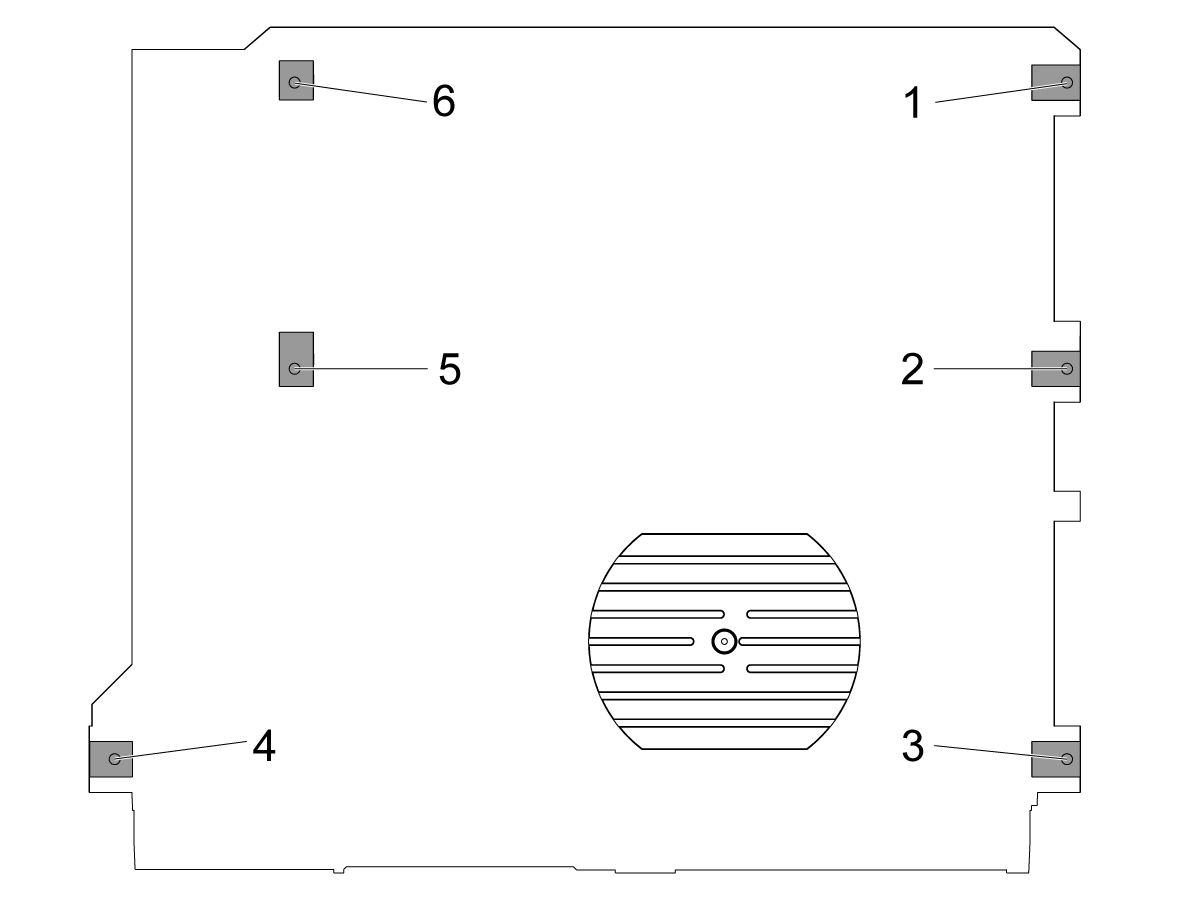
Lossa de mellersta Utjämnings skruvarna [2 och 5] så att de inte stöder någon vikt.

Ställ in maskinen på 4 hörn Utjämnings skruvar 3" (76,2 mm) ovanför golvet.

2

Grov nivå maskinen:

Vrid Utjämnings skruven #4 upp.

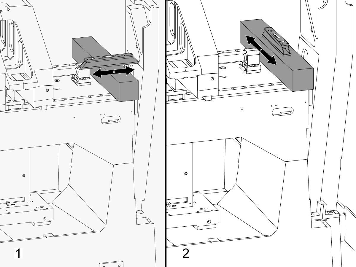
Placera graniten över X-axelns linjära styrskenor nära X-axelns stöd för kullager.

Ställ in den maskinistiska nivån ovanpå graniten parallellt med X-axeln. 1

Justera Utjämnings skruven #6 tills maskinen utjämnas i X-axeln.

Ställ in den maskinistiska nivån ovanpå granit vinkelrät mot X-axeln. 2

Justera Utjämnings skruven #3 tills maskinen utjämnas i Y-axeln.

Vrid Utjämnings skruven #4 ner tills den gör kontakten med Utjämnings plattan.

3

Justera X-axelns rulle:

Montera T-2192 med T-2181.

Flytta Y-axeln till mitten av resan.

Sätt T-2192 på sidan av spindeln.

Se till att bubblan på T-2181 är inom läsbart område.

Om det inte är det, lossa bulten som säkrar T-2192 till den magnetiska basen och flytta adaptern efter behov.

Jogga X-axeln sida till sida och mät X-axelrullen. Ta avläsningar på hempositionen, mitten, och slutet av resan.

Justera Utjämnings skruven #4 november det finns ingen avvikelse mellan behandlingen hemma position och läsningen i slutet av resan.

Obs! Bubblan på T-2181 behöver inte vara i mitten av injektionsflaskan. Den behöver bara vara inom läsbart område.

4

Ställ in de mellersta Utjämnings skruvarna:

Vrid mitten Utjämnings skruvar ner tills de gör kontakten med Utjämnings kuddar och sedan vända dem ytterligare 45 °.

Kontrollera X-axelns rulle. Justera de mellersta Utjämnings skruvarna för att korrigera X-axelns rulle.

X-axel till Y-Axeljustering

1

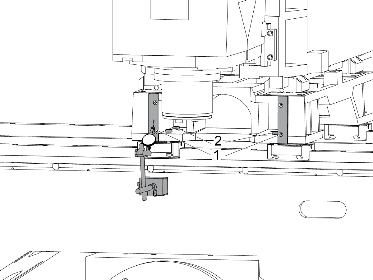
Rikta in sadel sidan parallellt med X-axelns rörelse:

Svep över den bearbetade ytan på framsidan av sadeln [1] genom att jogga X-axeln.

Lossa skruvarna som säkrar sadel till X-axelns lastbilar [2] och rikta in Sadelns framsida parallellt med X-axelrörelsen inom 0,001" om det behövs.

Vrid skruvarna. Se Haas fästmoment specifikationer.

2

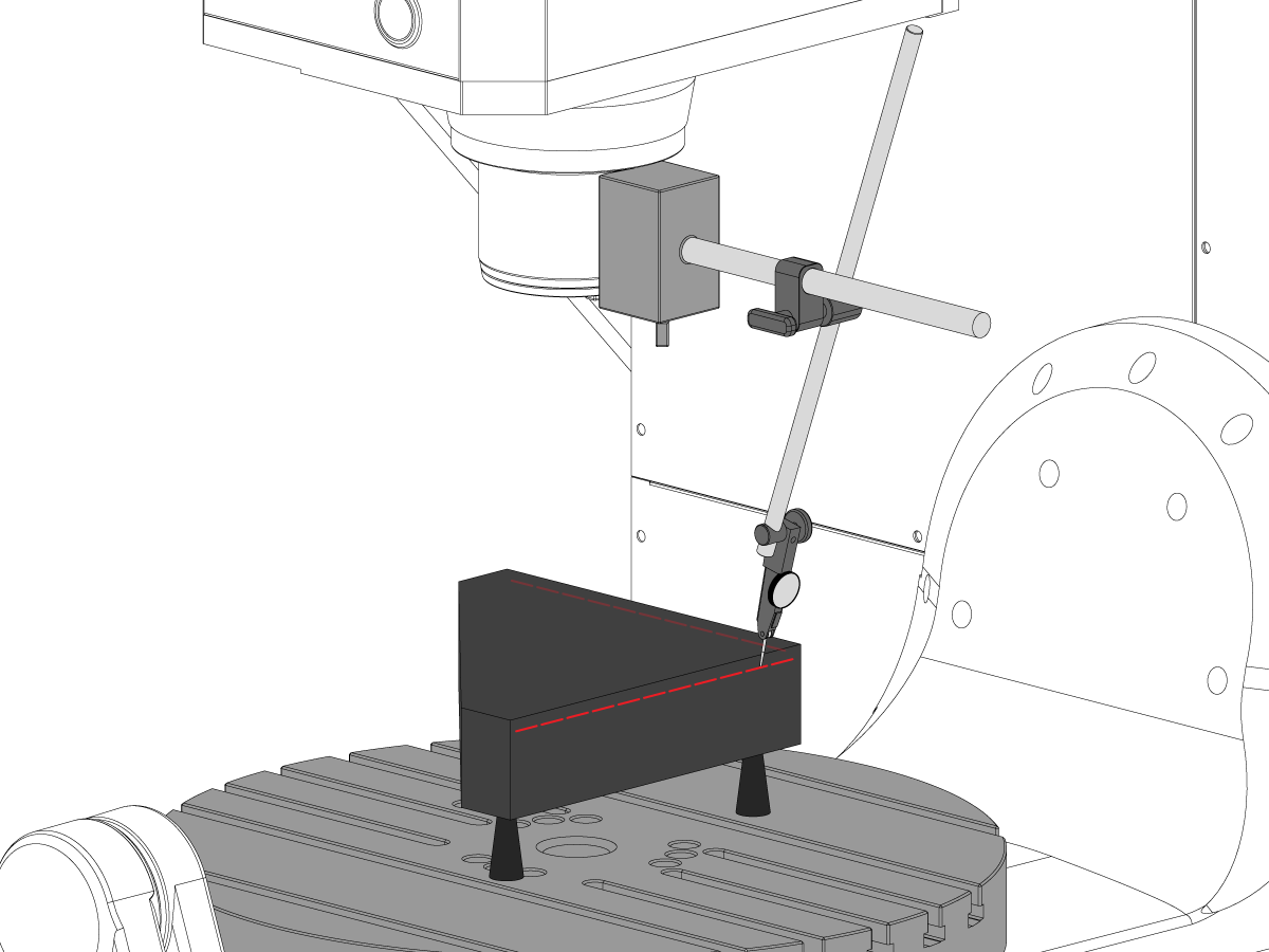
Justera Y-axeln vinkelrätt mot X-axeln:

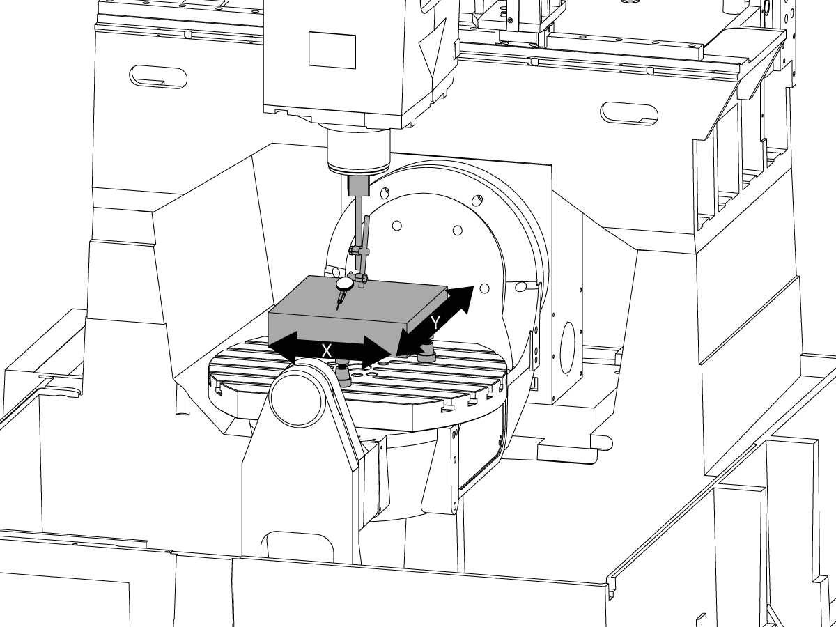
Ställ in Tri-kvadrat granit på vänster sida av C-axeln tallrik på maskinist uttagen.

Ställ baksidan av Tri-Square granit parallellt med X-axeln. NTE 0,0001"/10"

Svep toppen av Tri-Square granit längs X-och Y-axlarna.

Justera maskinistiska uttagen tills den övre ytan på Tri-Square granit är parallell med X-Y-planet NTE 0,0005".

Kontrollera att baksidan av graniten är parallell med X-axeln. NTE 0,0001"/10".

Lossa skruvarna som säkrar Y-axelns lastbilar till sadeln och justera Y-axeln vinkelrätt mot X-axeln. NTE 0,0005"/10"

Vrid skruvarna. Se Haas fästmoment specifikationer.

Kontrollera Y-axeln vinkelrät mot X-axeln NTE 0,0005"/10" efter skruvar är torqued.

Z-axeln till X-Y-planets justering

1

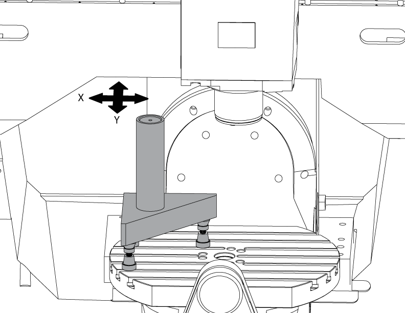
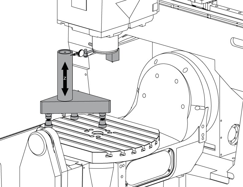
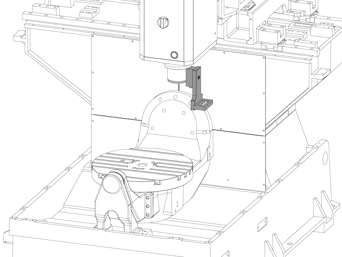
Ställ in cylindern.

Sätt en cylinder ovanpå Tri-stenen som visas på bilden.

Rikta in cylinderns övre yta parallellt med X-Y-planet NTE 0,0001" genom att vrida på maskinist-uttagen.

Jogga maskinen till följande position:

  • UMC-750 till X-7,000" och Y-10,000"
  • UMC-750SS till X-10,000" och Y-10,000"

2

Justera Z-axeln vinkelrätt mot X-axeln:

Ersätt en av de övre hörnbultarna på Z-axelns lastbilar med T-2193A * för att svänga spindelhuvudet runt den.

Ange sidan av cylindern längs Z-axeln.

Lossa skruvarna som säkrar Z-axelns lastbilar till RAM-minnet.

Justera Z-axeln vinkelrätt mot X-axeln NTE 0,0005"/10" genom Swinging spindlehead sida till sida.

Vrid skruvarna. Se Haas fästmoment specifikationer.

Kontrollera att Z-axeln vinkelrätt mot X-axeln efter bultar är torqued.

Byt T-2193A * mot bulten när justeringen är klar

*  : Används endast i Pre-Reboot-serien. 

3

Justera Z-axeln vinkelrätt mot Y-axeln:

Ange cylinder fronten längs Z-axeln.

Shim mellan Z-axel lastbilar och ram för att justera Z-axeln vinkelrätt mot Y-axeln NTE 0,0005"/10".

Observera: Shim antingen topp två lastbilar eller botten två lastbilar med lika shims.

Vrid skruvarna. Se Haas fästmoment specifikationer.

Kontrollera att Z-axeln vinkelrätt mot Y-och X-axlarna efter att bultarna är torqued.

4

Justera och vridmoment Y och Z axlar ballnut hus:

Lossa skruvarna som säkrar kulmuttern till höljet och bultarna som säkrar höljet till gjutningen.

Sätt fast bultarna som säkrar kulmuttern till gjutningen först och sätt sedan fast bultarna som säkrar kulmuttern på höljet.

Använd JOG lock-funktionen för att köra axeln fram och tillbaka hela resan.

Observera: Använd inte handratten eller snabb flyttningen.

Vrid skruvarna. Se Haas fästmoment specifikationer.

Y-axelns mutterhölje kan nås på baksidan av maskinen med ram jogged hela vägen mot framsidan av maskinen.

Z-axelns mutter hölje kan nås från maskinens framsida med spindelhuvudet jogged hela vägen ner.

Obs! Spindelmotor höljet måste avlägsnas för att få tillgång till Z-axelns kulmutter.

Spårvagn spindeln till X-Y-planet

1

Ställ in granit:

Ställ in de maskinistiska uttagen och graniten på mitten av C-axelns tallrik enligt bilden.

Rikta in den övre ytan på graniten parallellt med X-Y-planet genom att justera den maskinistiska knektar höjden NTE 0,0001".

Placera spindeln över mitten av plattan.

2

Spårvagn spindeln till X-Y-planet:

Sätt en indikator på spindelaxeln.

Gör en mätning ovanpå graniten vid varje 90 ° av rotation.

Lossa (6) bultarna i bottenplattan för spindelhuvudet.

Lägg till eller ta bort shims mellan spindelhuvudet gjutning och bottenplattan för att spårvagn spindeln till X-Y Plane NTE 0,0005"/10".

Obs! Använd shims av ojämn tjocklek [1] för att ändra vinkeln på bottenplattan.

När Svepet är inom specifikation, vridmoment (6) bultar. Se Haas fästmoment specifikationer.

Kontrollera spindel spårvagnen efter att skruvarna har torqued.

B-axel till XYZ-Axeljustering

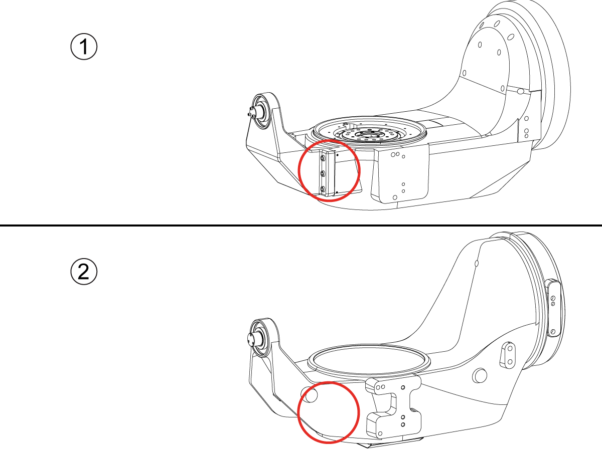
How to identify the Multi-Piece and the Unibody trunnion   

1) Multi-Piece trunnion:    UMC machines built approximetely before 11/2022 will have this configuration.

2) Unibody trunnion:    UMC machines built approximetely after 11/2022 will have this configuration.

1

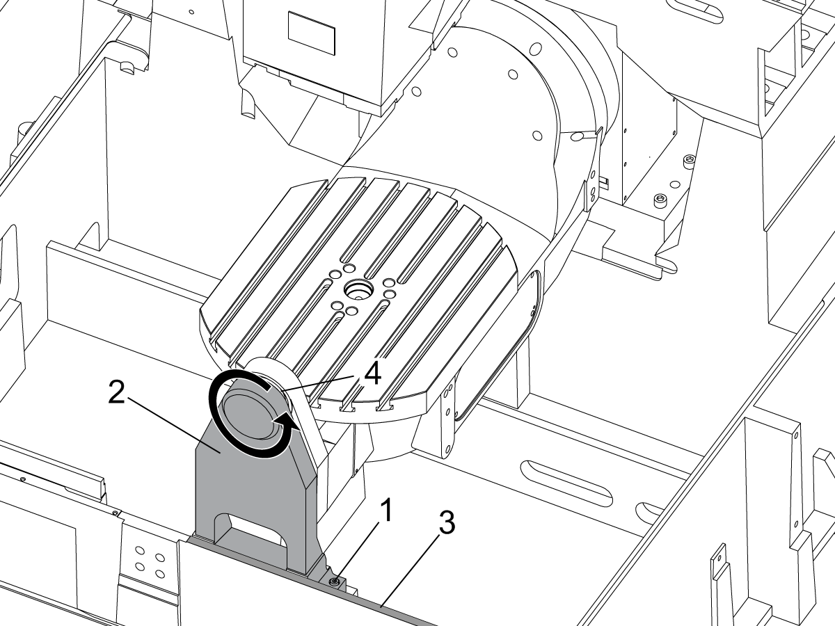
Remove the A-frame trunnion support:

Remove the bolts [1] that secure the A-frame trunnion support [2] to the base and take out the shims between A-frame support and the base.

Rotate the A-frame support [2] counter-clockwise to clear the edge of the base [3].

Pull the A-frame support off the bearings.

 Note: The A-frame support might vacuum lock on the bearings. Use the zip-tie to pry the seal [4] open.

 Caution: To lift the trunnion support, get the aid of another person. The support weighs 85 lbs (39 kg).

2

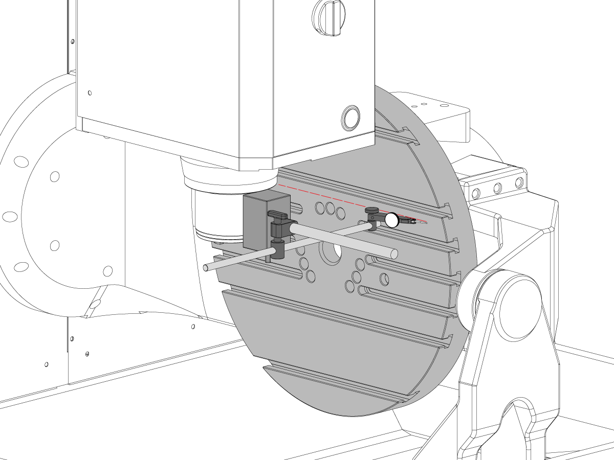
Measure the B- axis of rotation parallelism to the Y-Z plane:

For a machine with a Classic Haas Control, change Parameter 151:20 (B axis CHK TRAVL LIM) to 0.

For a machine with a Next Generation Control, change Parameter 6.021 (B axis CHK TRAVL LIM) to FALSE.

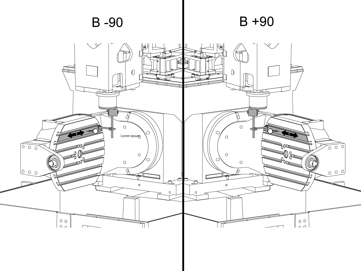
Measure the parallelism of the platter to the Y-Z plane with the B axis at 90° and then the B axis at -90° as shown in the picture.

Position the Y-Axis in the following starting position:

UMC-500: Y=0, Sweep 15”, 3rd T-Slot Land from the top.

UMC-750/1500-Duo: Y=-1.0, Sweep 18", 3rd T-Slot Land from the Top .

UMC-1250: Y=-1.0, Sweep 28", 3rd T-Slot Land from the Top.

UMC-500PP: Y=-4.0, Sweep 7".

UMC-750PP: Y=-2”, Sweep 15".

UMC-1000PP: Y=-4”, Sweep 15".

Compare the results at B 90° and B-90°. The results should be...

  • Symmetric against the Y-Z plane, positive or negative direction
  • Less than 0.0010"/20"

If the results are symmetric against Y-Z plane, and are less than 0.0010"/20 inches: Go to Step 5.

If the results are symmetric against Y-Z plane, but are more than 0.0010"/20 inches: Go to Step 4.

 Warning: If the results [3] are not symmetric against the Y-Z plane, the B axis rotary needs to be aligned: Go to Step 3.

3

Align the B axis of rotation parallel to the Y-Z plane:

Loosen the (6) bolts [1] that secure the B axis rotary to the base casting.

 Note: Keep the bolts sufficiently snug to control the adjustments.

Adjust the front and rear setscrews [2] until the measurements taken in Step 2 are symmetric against the Y-Z plane.

Torque the (6) bolts [1]. Refer to Haas Fastener Torque Specification.

Verify the measurements in Step 2 after the bolts have been torqued.

4

Align the C Axis of rotation perpendicular to the B Axis of rotation:

Remove the bottom C-Axis access cover.

Loosen the (12) bolts [1] that hold the C Axis body to the B Axis platter face.

Reach the bottom (4) bolts through the C Axis access port.

If the B Axis is symmetric in the positive direction [4], install horseshoe shims [2] of appropriate size behind the top (2) bolts.

If the B Axis is symmetric in the negative direction [5], install horseshoe shims [2] of appropriate size behind the bottom (2) bolts.

Torque the (12) bolts to 80 Ft-lbs (108 Nm).

Cut the excessive shim material off.

Verify the measurements in Step 2 after bolts are torqued.

5

Align the trunnion support shaft co-axial with the B Axis of rotation:

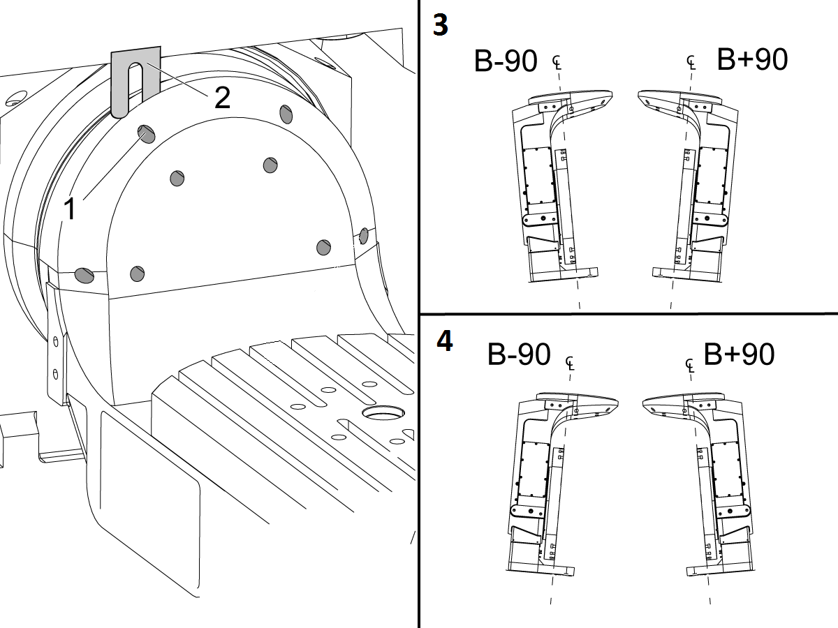
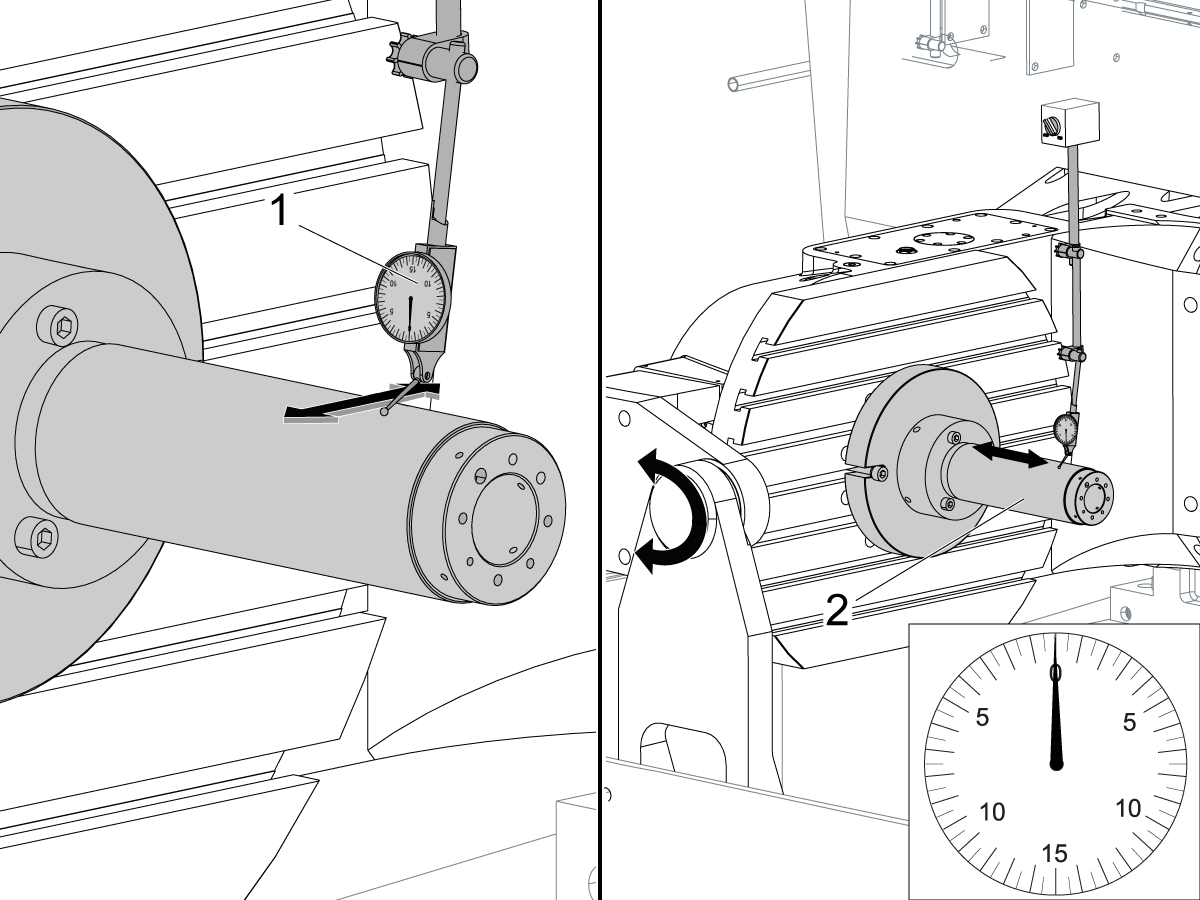
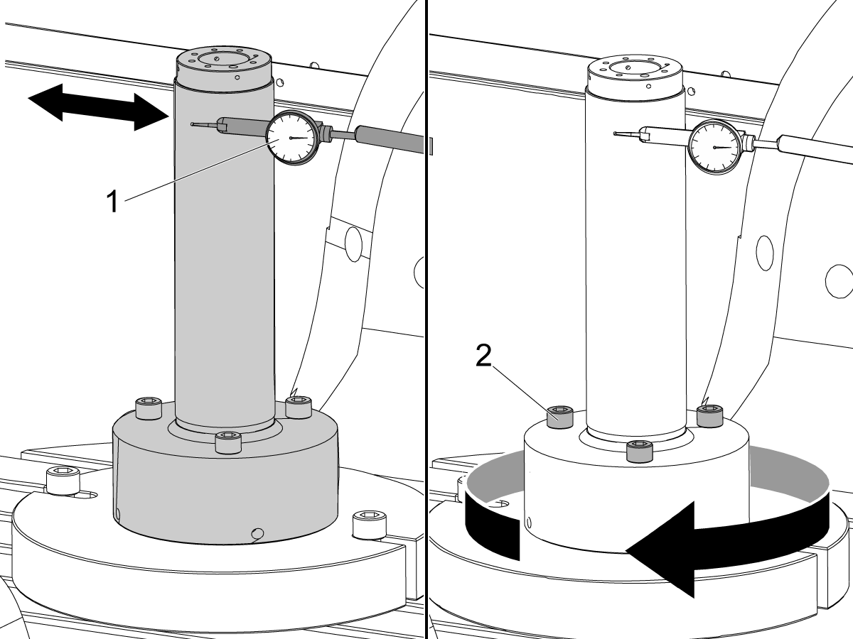
Setup (2) indicators on the outer race of the trunnion support bearing [2] as shown in the picture.

Mark the spot on the outer race where one of the indicator needles is contacting the surface.

After moving the B Axis to 90° or -90° you will align the marked spot with the needle again to exclude the bearing runout error from the measurements.

Take the readings when B is at 90° and B at -90°. Compare the readings. 

 Caution: The B axis brake needs to be clamped when taking the readings.

The deviation between the results when B is at 90° and at -90° needs to be less than 0.001" on each indicator.

 Note: The indicator on the side of the bearing will measure top to bottom alignment and the indicator on the top of the bearing will measure side to side alignment.

____

For models with a multi-piece trunnion

Loosen the (6) bolts [3] on the C Axis body support. Keep the bolts sufficiently snug to control adjustment.

Adjust the (8) set screws [4] until deviation between B at 90° and B at -90° is within 0.001".

Torque the (6) bolts [2] on the C Axis body support to 80 Ft-lbs (108 Nm).

Verify the alignment after the bolts have been torqued.

____

For models with a unibody trunnion

Jog rotary to B90. Set up an indicator on the highlighted surface as shown in the lower diagram .

Rotate B-axis 180 degrees (90 to -90).

Run out (NTE 0.010” TIR).

 Caution: If the measurement exceeds the tolerance then contact support.

6

Install and shim the A-frame trunnion support:

Move the B Axis to 90°.

Setup an indicator [1] against a machined surface of the C Axis body. Set the indicator to 0.

Use plastic zip ties [2] to pry the seal open while installing the A-frame support. This lets unwanted air and grease out of the assembly.

Install the A-frame trunnion support [3] over the bearings.

Remove the cable ties.

Turn the trunnion support clockwise until it is vertical.

 Note: The weight of the A-frame support will cause the trunnion to sag. The amount of sag is measured with the indicator that was previously setup on the side of the C Axis body.

____

For multi-piece trunnions

Adjust the shims [4] between the A-frame support and the base casting to remove the sag until indicator reads 0 again.

When the indicator reading is 0, torque the (4) bolts. Refer to Haas Fastener Torque Specification.

Verify the reading after bolts are torqued. Adjust the shims again if necessary until the indicator reads 0.

____

For models with unibody trunnion

Determine the amount of shim stock [4] needed to raise the Trunnion arm so the indicator reads 0.005".

The indicator [1] value will change once the support is torqued.

With indicator still in place:

  • Torque trunnion support bolts to appropriate values.
  • Check indicator to make sure it reads between the range of

Trunnion arm raised (0.005” to  0.010”).

 Note: For unibody trunnions, the shim location may also be used to correct the C-axis to X-Y plane perpendicularity instead of shimming the saddle trucks.

 Caution: Use equal amount of shims on each side of the A-frame support. Unequal shims will cause the A-frame support to pull the trunnion to the side.

Verify the B Axis of rotation alignment to the Y-Z plane (Step 2). Loosen the bolts and tap the A-frame support side to side if necessary to correct the B axis to Y-Z plane alignment.

7

Set C-axis perpendicular to X/Y plane:

Move the axes to

UMC-750's........X= -10.5" & Y=0."

UMC-1000's......X=-17.0" & Y=-0."

Zero an indicator [1], on a Ground Block [2], 1/2" off the edge at the rear of the platter (Mag-Base on Spindle), with C at 0 Degrees

Rotate C-Axis to 180°.

Move Y axis, and ground block, in Y Axis negative direction until you are 1/2" away from platter edge, and take the perpendicularity measurement

Adjust the shims until the average error is within 0.0005" end to end.

 Note: For unibody trunnions, the shim location under the bearing support may also be used to correct the C-axis to X-Y plane perpendicularity instead of shimming the saddle truck.

Caution: Shim either two front trucks or two rear trucks with the equal shim.

Note: Shim one truck at the time to maintain the X to Y squareness.

Verify the measurements after all bolts are torqued.

Verify the X to Y alignment in Step 2.

8

Set the tool change offsets:

B-axis tool change offset [1]

For Classic Haas Controls, change Parameter 213. 

For Next Generation Controls, go to: Settings>Rotary Tab>Highlight the rotary and press [INSERT], or change Parameter 6.078 (B TOOL CHANGE OFFSET) to set the trunnion (B Axis) parallel to the X Axis.

For models with multipiece trunnion

(NTE 0.001/10"; NTE 0.0020" overall)

For models with unibody trunnion

(NTE 0.0005/10"; NTE 0.0010" overall)

___

C-axis tool change offset [2]

For Classic Haas Controls change Parameter 523.

For Next Generation Control go to: Settings>Rotary Tab> Highlight the rotary and press [INSERT], or change Parameter 7.078 (C TOOL CHANGE OFFSET) to set the table T-slot (C Axis) parallel to the X Axis

For models with multipiece trunnion

(NTE 0.001/10"; NTE 0.0020" overall)

For models with unibody trunnion

(NTE 0.0005/10"; NTE 0.0010" overall)

9

Check C-axis perpendicularity to X/Y plane:

Align the indicator centered over the C-axis bore with the Y-axis at -10.

Jog positive in the Y-axis and align the indicator over the center of the last section of the platter and make a mark at this spot with a washable marker.

Insert 1-2-3 block as shown and set the indicator to zero.

Remove the block and rotate the platter 90 degrees, following the marked spot with the indicator.

Insert block back between the indicator and platter. Note reading.

Repeat the previous two steps, taking readings with the platter at 180, 270 and 360 degrees.

Multi-piece trunnion:  (NTE 0.0005")

Unibody trunnion: (NTE 0.001")

10

Measure the intersection of the B and C axis:

Follow the linked instruction manual to complete this step.

B-Axis and C-Axis intersection Adjustment

11

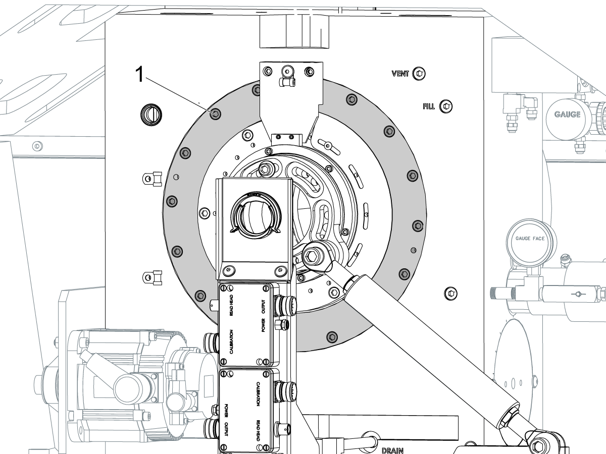
Align the B-Axis brake disk:

 Note: Do not do this step if you are working on a SS machine.

Operate this code in MDI mode to unclamp the brake:

M11;

Loosen all of the brake disc bolts [1] and torque them to 5 Ft-lbs (7 Nm).

Operate this code in MDI mode to clamp the brake:

M10;

Wait 10 seconds.

Torque the bolts. Refer to Haas Fastener Torque Specifications.

Ställ in parameter/inställning tillbaka till fabriksvärden

Ställ in Parameter 1314 för CHC/ Inställning 254 för NGC tillbaka till fabriksinställt värde. (Växla strömmen till maskinen efter att ha ändrat värdet.)

Allign och kalibrera WIPS. Trådlöst intuitivt sond system (WIPS)-kalibrering

Ställ in maskinens roterande Nollpoäng. 

  • UMC-750-MRZP WIPS förskjutningar inställningar-CHC
  • UMC-750-MRZP WIPS förskjutningar inställningar- Ngc

Fyll i fullständig inspektionsrapport:

  • EA0420 UMC-500 inspektionsrapport
  • EA0373 UMC-750 inspektionsrapport
  • EA0418 UMC-1000 inspektionsrapport

Lämna kopian av inspektionsrapporten med maskinen.

Om du ersatte B-och C-axlarnas montering gör UMC-750-B-axel och C-Axelskärnings punkt-justering

8.2 Inmätningszoner för uppriktning

Recently Updated

UMC inmätningszoner för uppriktning


AD0490

Inmätningszoner

1

X-axelns tippning

  • Fäst först verktyget T-2192 på spindelns sida.
  • För mätning av X-tippning ska Y- och Z-axlarnas positioner vara:
    • UMC 500 (Y,Z): -8, -8
    • UMC 750 (Y,Z): -10, -10
    • UMC 1000 (Y,Z): -12, -12
  • Mät X-axels tippning (max avvikelse 0,0005"/10")


2

Axelparallellitet B och Y

  • Kör nollpunktsåtergång på B- och C-axlarna.
  • Mät plattans kast på Y-axeln (max avvikelse 0,0008"/10", 0,0012"/15")
  • Mät sedan samma yta med B-axeln på både -90° och +90°  (max avvikelse 0,0008"/10", 0,0012"/15")
  • På UMC 500 och 750 mäts hela plattans längd
  • På UMC 1000, offset 2” från plattans kant och mät över 20”

3

Rätvinklighet Y/X-axlar

  • Ställ granitblocket parallellt med XY-planet med hjälp av lyftskruvar. (max avvikelse 0,0002")
  • Kontrollera sedan om Y är vinkelrät mot X (max avvikelse 0,0005"/10")

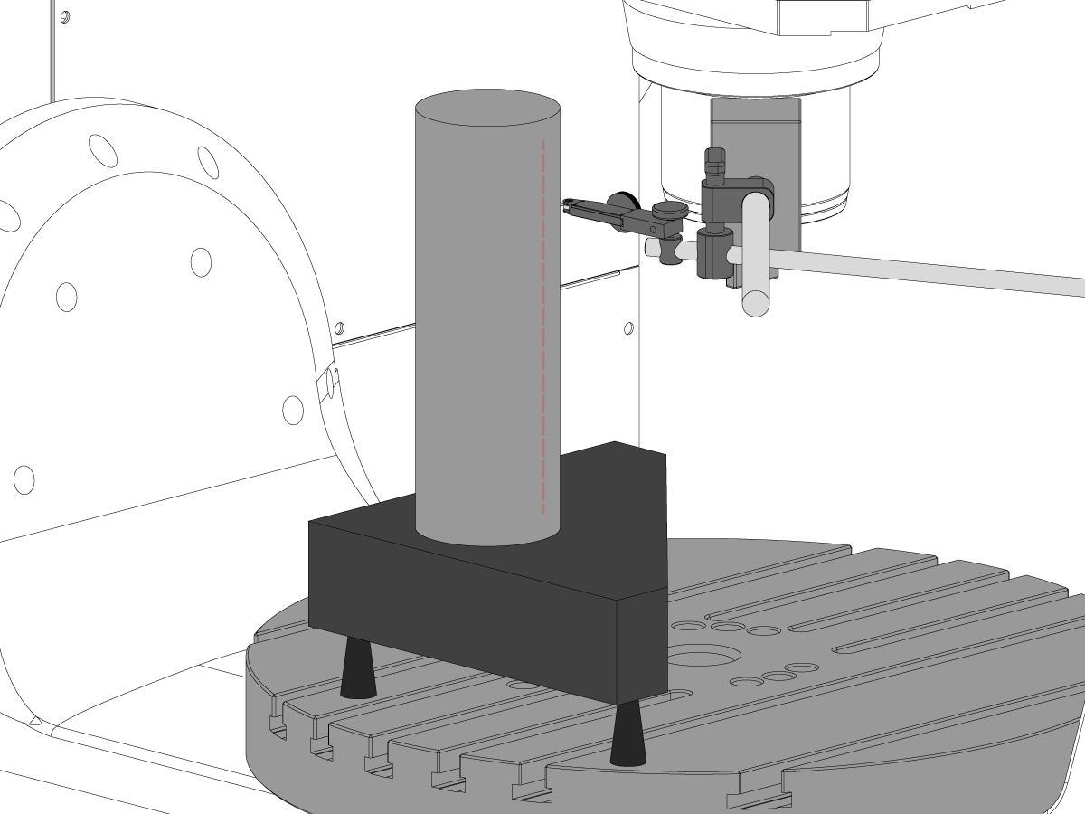
4

Rätvinklighet X/Z-axlar

  • Placera granitblock och precisionscylindern på plattan i den riktning som visas
  • Ställ granitblocket parallellt med XY-planet med hjälp av lyftskruvar. (max avvikelse 0,0002")
  • XY-spindelpositioner för detta steg:
    • UMC 500, X = -6, Y = -8
    • UMC 750, X = -10, Y = -10
    • UMC 1000, X = -17, Y = -12
  • Z-startposition för denna mätning:
    • UMC 500, Zstart= Ztop– 2”
    • UMC 750, Zstart= Ztop– 5”
    • UMC 1000, Zstart= Ztop– 7”
  • Ztop är gränsen för Z-axelrörelsen i positiv riktning (uppåt)
  • Från Zstart, mät ner 10” längs cylindern

5

Rätvinklighet Y/Z-axlar

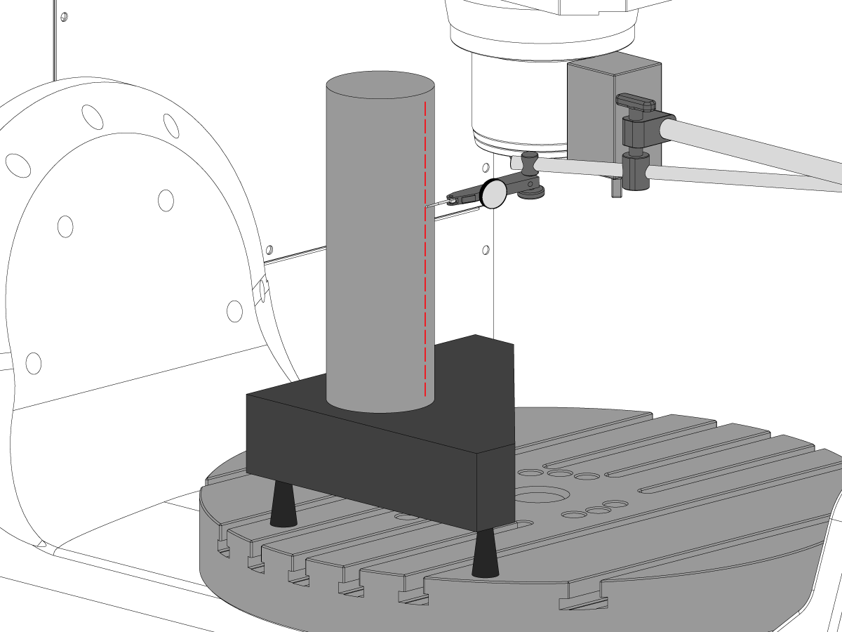
  • Placera granitblock och precisionscylindern på plattan i den riktning som visas
  • Ställ granitblocket parallellt med XY-planet med hjälp av lyftskruvar. (max avvikelse 0,0002")
  • XY-spindelpositioner för detta steg:
    • UMC 500, X = -6, Y = -8
    • UMC 750, X = -10, Y = -10
    • UMC 1000, X = -17, Y = -12
  • Z-startposition för denna mätning:
    • UMC 500, Zstart = Ztop – 2”
    • UMC 750, Zstart = Ztop – 5”
    • UMC 1000, Zstart = Ztop – 7”
  • Ztop är gränsen för Z-axelrörelsen i positiv riktning (uppåt).
  • Från Zstart, mät ner 10” längs cylindern

6

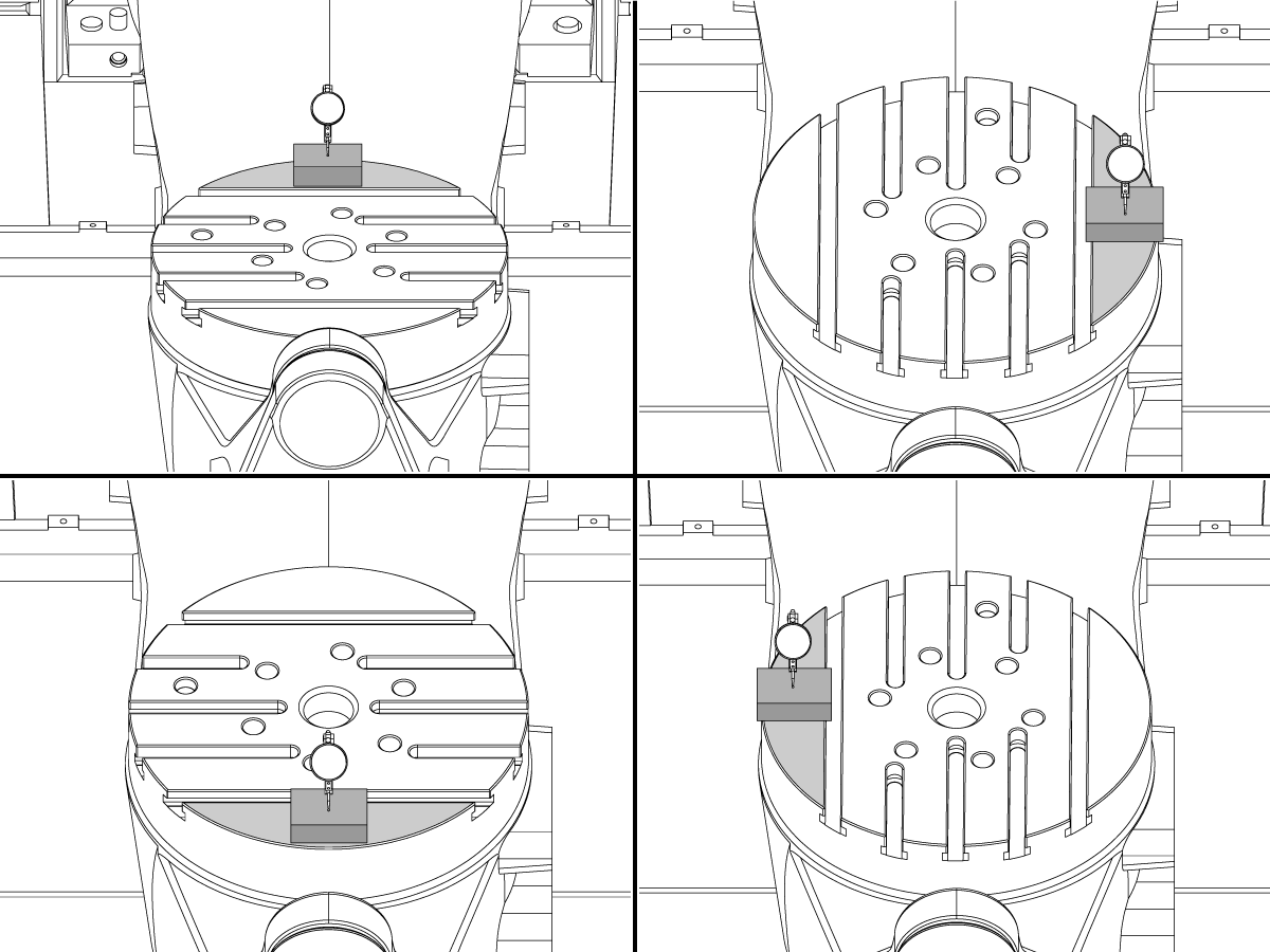
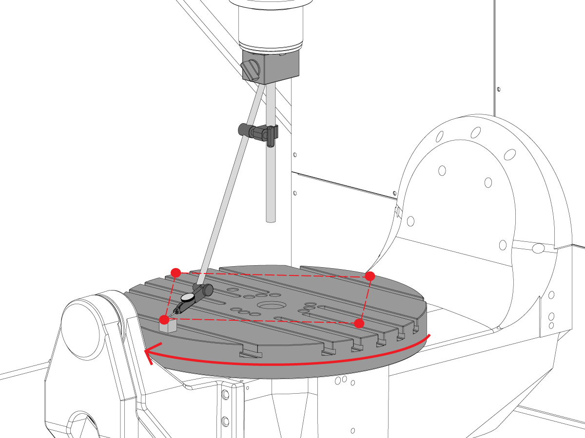
C-axelns rätvinklighet mot XY-planet

  • Flytta magnetfoten till spindeln så att den inte kan rotera med spindeln.
  • Placera precisionsblocket vid kanten av plattan i position klockan 12. 
  • Nollställ mätspetsen på mätarblocket i denna position.
  • Rotera C-axeln  90° 
  • Jogga sedan spindeln i X- och Y-led så att den följer mätblocket och gör en avläsning på samma punkt på plattan. Spindeln ska inte rotera
  • Upprepa detta ytterligare 2 gånger för totalt 4 positioner, 90° mellanrum, vid pplattans kant enligt bilden. 
  • Skillnaden mellan mätningarna vid positionerna klockan 12 och klockan 6 bestämmer planheten längs X-axeln (max avvikelse 0,0005")
  • Skillnaden mellan mätningarna vid positionerna klockan 3 och klockan 9 bestämmer planheten längs Y-axeln (max avvikelse 0,0005 )

7

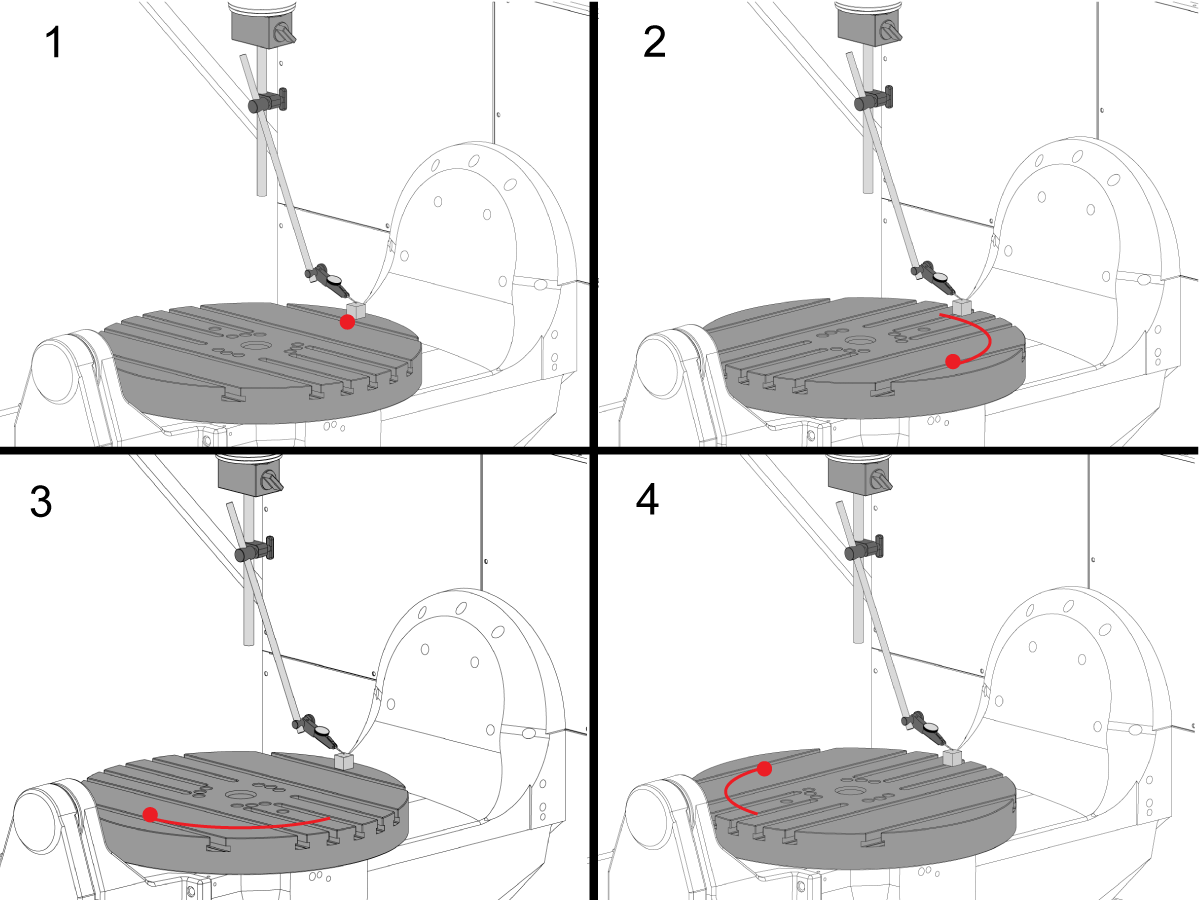
Plattytans kast

ANM.: C-axelbromsen är avstängd för detta steg

  • Placera precisionsblocket vid kanten av plattan i position klockan 12. 
  • Nollställ mätspetsen på mätarblocket i denna position.
  • Rotera C-axeln  90°, men behåll mätblocket vid position klockan 12
  • Gör en avläsning vid mätblockets överkant
  • Upprepa detta ytterligare 2 gånger för totalt 4 positioner, 90° mellanrum, vid pplattans kant enligt bilden. 
  • Notera totalt uppmätt kast. (Max avvikelse 0,001")

8

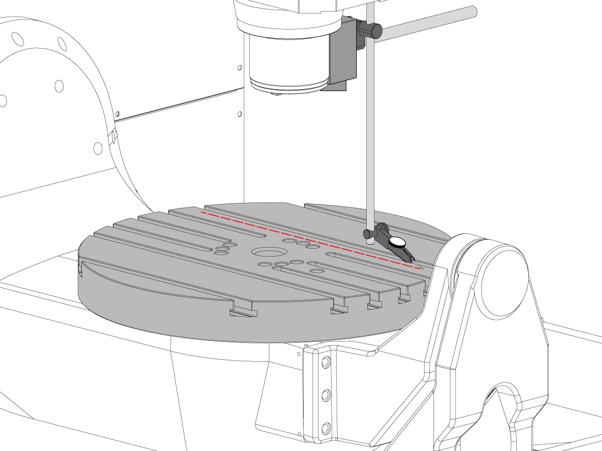
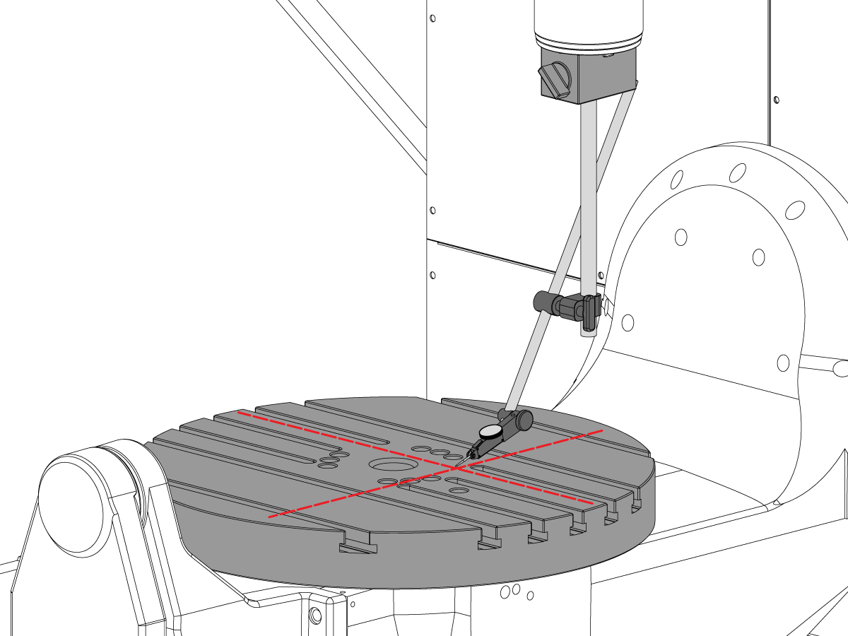
Plattytans parallellitet mot XY-planet

  • Kör nollpunktsåtergång på C-axeln så att T-spåren löper parallellt med X-axeln
  • Placera mätspetsen på plattan och jogga X-axeln längs plattan för att mäta X-axelns parallellitet mot plattan (max avvikelse 0,001"/10, 0,0015"/15")
  • Jogga sedan Y axeln längs plattan för att mäta Y-axelns parallellitet mot plattan (max avvikelse 0,001"/10, 0,0015"/15"

9

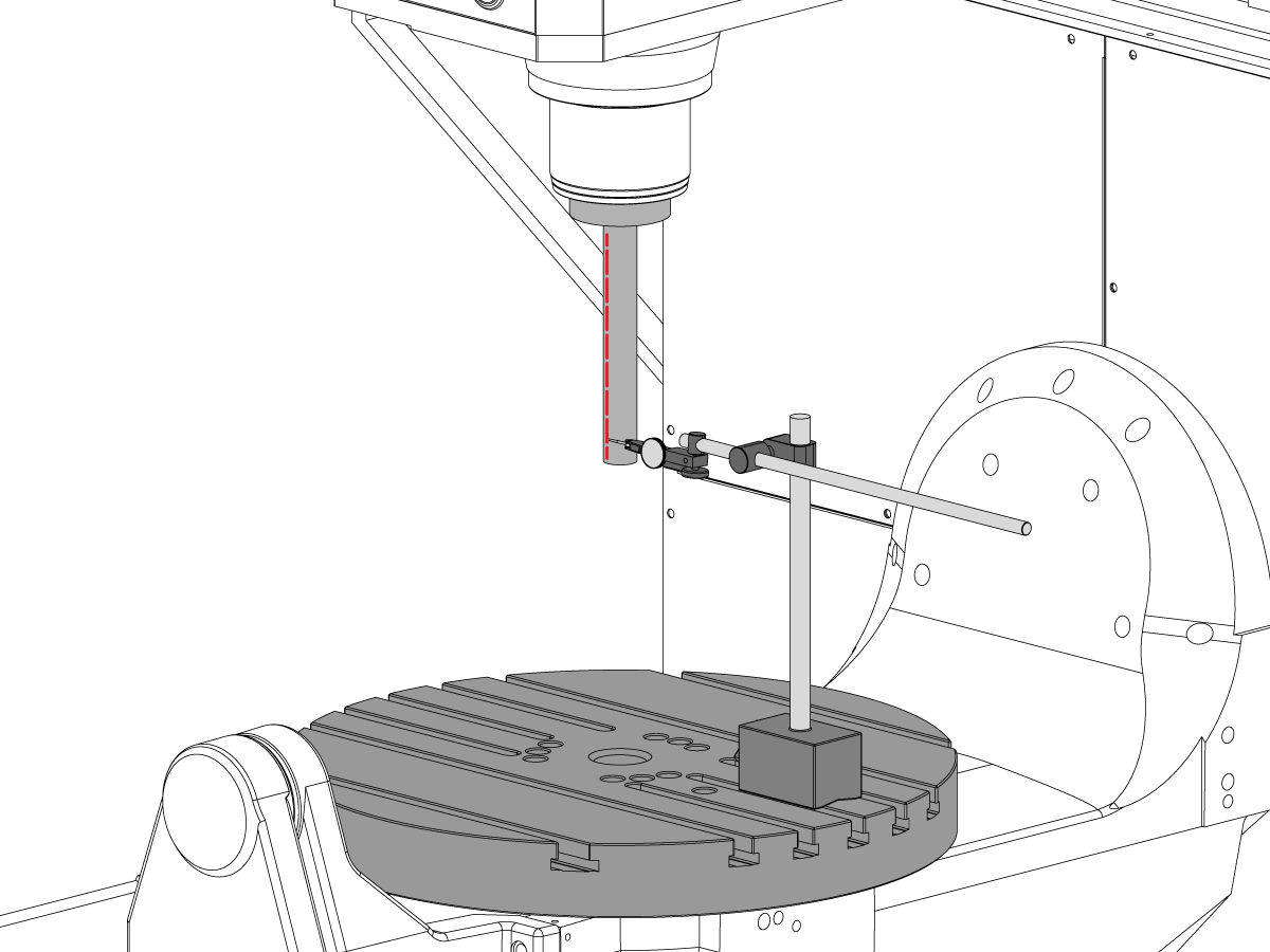
Spindelkast

  • Centrera spindeln över C-axelhålet.
  • Placera magnetfoten på bordet och sätt i spindeltolken.
  • Kontrollera spindelns kast vid teststångens fot (max avvikelse 0,0005" TIR)
  • Kontrollera spindelns kast 6" ned från teststångens fot (max avvikelse 0,001" TIR)

10

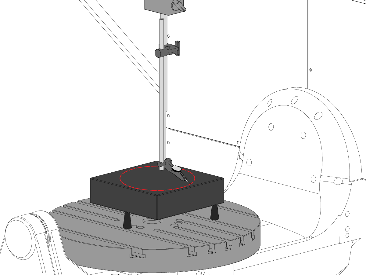
Parallellitet mellan spindelns centrumlinje och Z-axeln

  • Ställ granitblocket parallellt med XY-planet med hjälp av lyftskruvar (max avvikelse 0,0002")
  • Centrera spindeln över C-axelhålet.
  • Svep i cirkel med 10" diameter
  • Anteckna XZ TIR  (max avvikelse 0,0005")
  • Anteckna YZ TIR  (max avvikelse 0,0005")

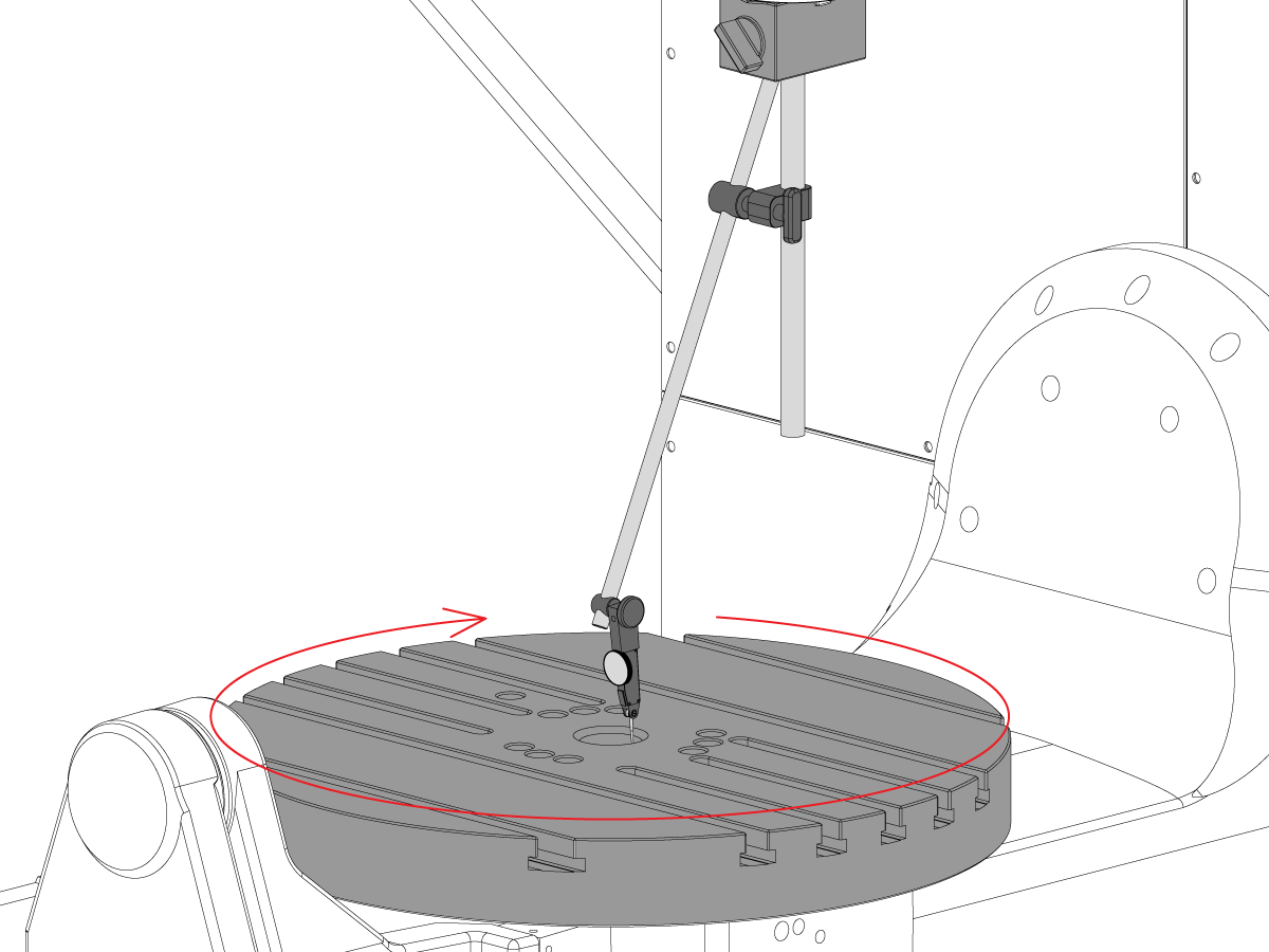
11

C-axelhålets koncentricitet

  • Placera mätklockan enligt bild och jogga C-axeln 360°
  • Anteckna TIR för precisionshålet (max avvikelse 0,002")

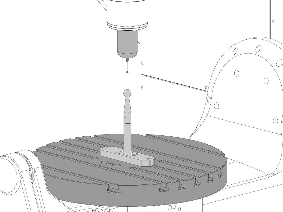
12

Maskinens rotationscentrumpunkt (MRZP)

  • Använd VQC-makroprogrammet och sondsystemet för att verifiera värdena för Coldfire-parametrarna eller NGC-inställningarna som visas nedan:
    • 255 – MRZP-X-offset
    • 256 – MRZP-Y-offset
    • 257 – MRZP-Z-offset
    • 254 - Centrumavstånd för 5:e axel på rundmatningsbord
  • För en fullständig MRZP-instruktion, se procedur Ställa in offset för MRZP WIPS 

8.3 Geometrifelsökning

Recently Updated

UMC geometrifelsökning


TG0151

Översikt

Innan du felsöker en UMC-750 noggrannhet eller geometri problem, måste den tekniska ha en grundlig förståelse av följande grunder:

  • Hur man jämnar och justerar de roterande axlarna för UMC
  • Så här justerar du om alla axlar på enheten
  • Hur man utför mrzp kalibrering och ett grundlig samförstånd av vad de associerade parametrarna är, och deras effekter på maskinen
  • En förståelse av maskinerna noggrannhet kapacitet och förmågan att resonera om geometriska problem
  • B- till C-axelskärningspunktsjustering

Ett problem med UMC-750 maskingeometri eller noggrannhet måste närma sig systematiskt och i rätt ordning. Följande information bör följas strikt och följas i sekventiell ordning.

Det är absolut viktigt att innan någon bedömning eller justering görs av maskinens geometri att maskinen har kontrollerats för korrekt nivå och anpassning av roterande axlar till maskinen

Många fel kan tillskrivas den maskin som drabbats av en krasch eller problem antingen med verktygsprogram eller programmeringsproblem. Försök inte ändra maskinens geometri utan att helt kontrollera maskinernas totala nivå och geometri enligt inspektionsrapporten. Detta inbegriper kontroll av Machine Rotary Zero Point (MRZP).

I händelse av en krasch finns det 4 slipfogar på maskinen. Dessa områden är spindelhuvudet till ram, ram till sadeln, sadeln till bryggan, och midjefäste till midjefäste stöd.

 Observera: ingen av dessa fogar bör någonsin mellanläggas. En maskinkrasch bör aldrig ändra mängden mellanlägg som krävs i maskinen från fabriksinställningarna.

Det är viktigt att komma ihåg den linjära noggrannheten hos maskinen är 0.0004/10" och vinkelprecisionen är +/-15 båg. sek. Dessa toleranser kan snabbt läggas till.

Varje ansträngning bör vara uttömd för att avgöra om bearbetningsprogrammet är rimligt och inom maskinen, fixturering och verktygsförmåga.

Bedöm maskinens skick

Ta reda på om datorn kraschade tidigare. Granska larmhistoriken; leta efter fysiska skador på plåt, bord, spindelhuvud, etc. Oavsett hur "Mindre" kraschen var, kommer det att påverka maskinens geometri. Om maskinen har kraschat måste en fullständig inspektion av maskinernas geometri utföras

Bedömer det allmänna tillståndet för delfixturering och skicket på skärverktygen.

Få fullständig maskin backup och felrapport.

Kontrollera maskinnivå och geometri

Kontrollera att maskinen är i nivå och att rotationsaxeln är justerad mot maskinen

 Observera: Försök inte göra några justeringar av maskinens geometri annat än att justera nivå fötterna vid denna tidpunkt.

Om maskinen är ur nivå eller om rotorny inte är justerad, återställ nivå och roterande justering.

Utför full geometriinspektion notera magnitud och riktning av eventuella fel för varje axel.

Analysera inspektionsrapporten.

Om någon av avsnitten i inspektionsrapporten är ur tolerans, behöver maskinen justeras på nytt.

Granska ansökan

Samla in följande information om delen, arbetsstycke och verktyg:

  • Vilka funktioner som är av tolerans, storlek, felriktning
  • Bearbetas delen med 5-axlig, 3 + 2-axel eller 3-axel?
  • Granska delen och bearbetningsmetoden
  • Kan något av delprecisionsfelen minimeras genom att ändra bearbetningsmetoden?
  • Är problemet en repeterbarhetsfråga, en storleksfråga eller en geometrisk fråga?
  • Använder programmet TCPC eller DWO?
  • Finns det några värden i kompensations tabellerna?

8.4 Tillämpningar – Felsökning

Recently Updated

UMC programfelsökningsguide


TG0150

Så här öppnar du

Se UMC – Tillämpningar – Felsökning:

Följ denna länk Dokument och programvara | HBC

eller

Logga in på hbc.haascnc.com

ANM.: Endast Haas-certifierade servicetekniker kan logga in på den här webbplatsen. 

Välj fliken Service.

Gå till Utilities och välj Documents and Software.

Välj mappen Tillämpningar.

8.5 UMC-750 – Checklista för mellanläggssats

Recently Updated

UMC-750 – Checklista för shimssats


AD0131

Inledning

Detta är shimssatsens checklista för följande sats:

  • 93-2236 , MELLANLÄGGSSATS FÖR UMC-750

Checklista: Mellanlägg-Mellanlägg-Kolumn

Tjocklek Detaljnr Antal i satsen Används
0,02100 20-9358A 2  
0,2105 20-9359A 2  
0,02110 20-9383A 2  
0,2115 20-9365A 2  
0,2120 20-9384A 2  
0,2125 20-9385A 2  
0,2130 20-9368A 2  
0,2135 20-9369A 2  
0,2140 20-9386A 2  
0,2145 20-9371A 2  
0,2150 20-9372A 2  
0,2155 20-9387A 2  
0,2160 20-9374A 2  
0,2165 20-9375A 2  
0,2170 20-9376A 2  
0,2175 20-9377A 2  
0,2180 20-9378A 2  
0,2185 20-9379A 2  
0,2190 20-9380A 2  
0,2195 20-9381A 2  
0,2200 20-9382A 2  

Anm.: Observera:Endast satsägare: Ange shimstjockleken när du beställer ersättningar. Till exempel 20-9382 0,2145

Checklista: Horshoe-shims

Tjocklek Detaljnr Antal i satsen Används
0,0010 59-0240 2  
0,0020 59-0241 2  
0,0030 59-0242 2  

Checklista: Mellanlägg-Mellanlägg-Kolumn-Stor

Tjocklek Detaljnr Antal i satsen Används
0,2130 20-6282A 2  
0,2135 20-6283A 2  
0,2140 20-6284A 2  
0,2145 20-6285A 2  
0,2150 20-6286A 2  
0,2155 20-6287A 2  
0,2160 20-6288A 2  
0,2165 20-6289A 2  
0,2170 20-6290A
2  
0,2175 20-6291A 2  
0,2180 20-6294A 2  
0,2185 20-6295A 2  
0,2190 20-6292A 2  
0,2195 20-6293A 2  
0,2200 20-6296A 2  
0,2205 20-6297A 2  
0,2210 20-6277A 2  
0,2215 20-6279A 2  
0,2220 20-6278A 2  
0,2225 20-6298A 2  
0,2230 20-6281A 2  

Anm.: Observera:Endast satsägare: Ange shimstjockleken när du beställer ersättningar. Till exempel 20-6290A 0,2080

REGISTRERA VILKA SHIMS TOGS BORT FRÅN SATSEN I KOLUMNEN ANVÄNDS.

RETURNERA CHECK LISTAN MED SHIM-SATSEN.

RETURNERA DEN URSPRUNGLIGA SHIMS I LÅDAN.

8.6 Korsande B- och C-axel – Uppriktning

Inledning

I den här proceduren visas hur du mäter och justerar skärningspunkten för B-och C-axlarna.  Innan du försöker den här proceduren ska du kontrollera att enheten UMC-750 utjämning.

Du måste justera B-och C-axlarna efter att du har antingen:

  • Byt ut B-och C-axlarna
  • eller slutföra en UMC inspektion rapportera och hitta ett problem

5-axlig rotationscentrum avstånd definierar skillnaden mellan rotationscentrum rotation: C-axeln maskin Rotory Zero Point (MRZP) och B-axeln MRZP i X-axeln.

Det är möjligt att det inte finns någon skillnad mellan C-axeln och B-axeln MRZP.

  • Classic Haas Control (CHC): Parameter 1314 - Rotary Axes Center Deviation in X
  • Nästa generations kontrollsystem Inställning 254. 5 Axis Rotary Center Distance

Du kommer att behöva följande verktyg:

  • T-2195A UMC Aligment Bar Adapter
  • T-2113 Alignment bar
  • Värmepistol och värmetåliga handskar

B-axel till XYZ-Axeljustering

How to identify the Multi-Piece and the Unibody trunnion   

1) Multi-Piece trunnion:    UMC machines built approximetely before 11/2022 will have this configuration.

2) Unibody trunnion:    UMC machines built approximetely after 11/2022 will have this configuration.

1

Remove the A-frame trunnion support:

Remove the bolts [1] that secure the A-frame trunnion support [2] to the base and take out the shims between A-frame support and the base.

Rotate the A-frame support [2] counter-clockwise to clear the edge of the base [3].

Pull the A-frame support off the bearings.

 Note: The A-frame support might vacuum lock on the bearings. Use the zip-tie to pry the seal [4] open.

 Caution: To lift the trunnion support, get the aid of another person. The support weighs 85 lbs (39 kg).

2

Measure the B- axis of rotation parallelism to the Y-Z plane:

For a machine with a Classic Haas Control, change Parameter 151:20 (B axis CHK TRAVL LIM) to 0.

For a machine with a Next Generation Control, change Parameter 6.021 (B axis CHK TRAVL LIM) to FALSE.

Measure the parallelism of the platter to the Y-Z plane with the B axis at 90° and then the B axis at -90° as shown in the picture.

Position the Y-Axis in the following starting position:

UMC-500: Y=0, Sweep 15”, 3rd T-Slot Land from the top.

UMC-750/1500-Duo: Y=-1.0, Sweep 18", 3rd T-Slot Land from the Top .

UMC-1250: Y=-1.0, Sweep 28", 3rd T-Slot Land from the Top.

UMC-500PP: Y=-4.0, Sweep 7".

UMC-750PP: Y=-2”, Sweep 15".

UMC-1000PP: Y=-4”, Sweep 15".

Compare the results at B 90° and B-90°. The results should be...

  • Symmetric against the Y-Z plane, positive or negative direction
  • Less than 0.0010"/20"

If the results are symmetric against Y-Z plane, and are less than 0.0010"/20 inches: Go to Step 5.

If the results are symmetric against Y-Z plane, but are more than 0.0010"/20 inches: Go to Step 4.

 Warning: If the results [3] are not symmetric against the Y-Z plane, the B axis rotary needs to be aligned: Go to Step 3.

3

Align the B axis of rotation parallel to the Y-Z plane:

Loosen the (6) bolts [1] that secure the B axis rotary to the base casting.

 Note: Keep the bolts sufficiently snug to control the adjustments.

Adjust the front and rear setscrews [2] until the measurements taken in Step 2 are symmetric against the Y-Z plane.

Torque the (6) bolts [1]. Refer to Haas Fastener Torque Specification.

Verify the measurements in Step 2 after the bolts have been torqued.

4

Align the C Axis of rotation perpendicular to the B Axis of rotation:

Remove the bottom C-Axis access cover.

Loosen the (12) bolts [1] that hold the C Axis body to the B Axis platter face.

Reach the bottom (4) bolts through the C Axis access port.

If the B Axis is symmetric in the positive direction [4], install horseshoe shims [2] of appropriate size behind the top (2) bolts.

If the B Axis is symmetric in the negative direction [5], install horseshoe shims [2] of appropriate size behind the bottom (2) bolts.

Torque the (12) bolts to 80 Ft-lbs (108 Nm).

Cut the excessive shim material off.

Verify the measurements in Step 2 after bolts are torqued.

5

Align the trunnion support shaft co-axial with the B Axis of rotation:

Setup (2) indicators on the outer race of the trunnion support bearing [2] as shown in the picture.

Mark the spot on the outer race where one of the indicator needles is contacting the surface.

After moving the B Axis to 90° or -90° you will align the marked spot with the needle again to exclude the bearing runout error from the measurements.

Take the readings when B is at 90° and B at -90°. Compare the readings. 

 Caution: The B axis brake needs to be clamped when taking the readings.

The deviation between the results when B is at 90° and at -90° needs to be less than 0.001" on each indicator.

 Note: The indicator on the side of the bearing will measure top to bottom alignment and the indicator on the top of the bearing will measure side to side alignment.

____

For models with a multi-piece trunnion

Loosen the (6) bolts [3] on the C Axis body support. Keep the bolts sufficiently snug to control adjustment.

Adjust the (8) set screws [4] until deviation between B at 90° and B at -90° is within 0.001".

Torque the (6) bolts [2] on the C Axis body support to 80 Ft-lbs (108 Nm).

Verify the alignment after the bolts have been torqued.

____

For models with a unibody trunnion

Jog rotary to B90. Set up an indicator on the highlighted surface as shown in the lower diagram .

Rotate B-axis 180 degrees (90 to -90).

Run out (NTE 0.010” TIR).

 Caution: If the measurement exceeds the tolerance then contact support.

6

Install and shim the A-frame trunnion support:

Move the B Axis to 90°.

Setup an indicator [1] against a machined surface of the C Axis body. Set the indicator to 0.

Use plastic zip ties [2] to pry the seal open while installing the A-frame support. This lets unwanted air and grease out of the assembly.

Install the A-frame trunnion support [3] over the bearings.

Remove the cable ties.

Turn the trunnion support clockwise until it is vertical.

 Note: The weight of the A-frame support will cause the trunnion to sag. The amount of sag is measured with the indicator that was previously setup on the side of the C Axis body.

____

For multi-piece trunnions

Adjust the shims [4] between the A-frame support and the base casting to remove the sag until indicator reads 0 again.

When the indicator reading is 0, torque the (4) bolts. Refer to Haas Fastener Torque Specification.

Verify the reading after bolts are torqued. Adjust the shims again if necessary until the indicator reads 0.

____

For models with unibody trunnion

Determine the amount of shim stock [4] needed to raise the Trunnion arm so the indicator reads 0.005".

The indicator [1] value will change once the support is torqued.

With indicator still in place:

  • Torque trunnion support bolts to appropriate values.
  • Check indicator to make sure it reads between the range of

Trunnion arm raised (0.005” to  0.010”).

 Note: For unibody trunnions, the shim location may also be used to correct the C-axis to X-Y plane perpendicularity instead of shimming the saddle trucks.

 Caution: Use equal amount of shims on each side of the A-frame support. Unequal shims will cause the A-frame support to pull the trunnion to the side.

Verify the B Axis of rotation alignment to the Y-Z plane (Step 2). Loosen the bolts and tap the A-frame support side to side if necessary to correct the B axis to Y-Z plane alignment.

7

Set C-axis perpendicular to X/Y plane:

Move the axes to

UMC-750's........X= -10.5" & Y=0."

UMC-1000's......X=-17.0" & Y=-0."

Zero an indicator [1], on a Ground Block [2], 1/2" off the edge at the rear of the platter (Mag-Base on Spindle), with C at 0 Degrees

Rotate C-Axis to 180°.

Move Y axis, and ground block, in Y Axis negative direction until you are 1/2" away from platter edge, and take the perpendicularity measurement

Adjust the shims until the average error is within 0.0005" end to end.

 Note: For unibody trunnions, the shim location under the bearing support may also be used to correct the C-axis to X-Y plane perpendicularity instead of shimming the saddle truck.

Caution: Shim either two front trucks or two rear trucks with the equal shim.

Note: Shim one truck at the time to maintain the X to Y squareness.

Verify the measurements after all bolts are torqued.

Verify the X to Y alignment in Step 2.

8

Set the tool change offsets:

B-axis tool change offset [1]

For Classic Haas Controls, change Parameter 213. 

For Next Generation Controls, go to: Settings>Rotary Tab>Highlight the rotary and press [INSERT], or change Parameter 6.078 (B TOOL CHANGE OFFSET) to set the trunnion (B Axis) parallel to the X Axis.

For models with multipiece trunnion

(NTE 0.001/10"; NTE 0.0020" overall)

For models with unibody trunnion

(NTE 0.0005/10"; NTE 0.0010" overall)

___

C-axis tool change offset [2]

For Classic Haas Controls change Parameter 523.

For Next Generation Control go to: Settings>Rotary Tab> Highlight the rotary and press [INSERT], or change Parameter 7.078 (C TOOL CHANGE OFFSET) to set the table T-slot (C Axis) parallel to the X Axis

For models with multipiece trunnion

(NTE 0.001/10"; NTE 0.0020" overall)

For models with unibody trunnion

(NTE 0.0005/10"; NTE 0.0010" overall)

9

Check C-axis perpendicularity to X/Y plane:

Align the indicator centered over the C-axis bore with the Y-axis at -10.

Jog positive in the Y-axis and align the indicator over the center of the last section of the platter and make a mark at this spot with a washable marker.

Insert 1-2-3 block as shown and set the indicator to zero.

Remove the block and rotate the platter 90 degrees, following the marked spot with the indicator.

Insert block back between the indicator and platter. Note reading.

Repeat the previous two steps, taking readings with the platter at 180, 270 and 360 degrees.

Multi-piece trunnion:  (NTE 0.0005")

Unibody trunnion: (NTE 0.001")

10

Measure the intersection of the B and C axis:

Follow the linked instruction manual to complete this step.

B-Axis and C-Axis intersection Adjustment

11

Align the B-Axis brake disk:

 Note: Do not do this step if you are working on a SS machine.

Operate this code in MDI mode to unclamp the brake:

M11;

Loosen all of the brake disc bolts [1] and torque them to 5 Ft-lbs (7 Nm).

Operate this code in MDI mode to clamp the brake:

M10;

Wait 10 seconds.

Torque the bolts. Refer to Haas Fastener Torque Specifications.

B axel till C axel skärnings verktyget setup

1

Install the B Axis and C Axis intersection tool:

Jog the C Axis to 0°.

Push [EMERGENCY STOP].

Clean the table.

Guide the shaft of the adapter [1] while you slowly lower it into the center bore.

Attach the adapter to the table with (2) screws [4] and (2) T-nuts.

Attach the alignment bar [2] to the adapter with (3) screws [3].

Snug the (3) screws to allow for adjustments in the next step.

2

Align the B/C intersection tool with the C Axis:

Put an indicator on the front side of the alignment bar near the base.

Release the [EMERGENCY STOP]. Push [RESET] to clear any alarms.

Jog across the tool in the X Axis to find the high spot.

Set the indicator to 0.

Jog the C Axis 360°.

Lightly tap the base with a rubber mallet to adjust the radial error on the alignment bar.

Note: Adjust the alignment bar to half of the measured error, because you are measuring the diameter error.

Jog the C Axis 360°.

When correctly adjusted the radial error is less than 0.0002" (0.005 mm).

3

Check the B/C intersection:

Center the indicator [1] on the front side of the alignment bar near the top of the cylinder.

Jog across the tool in the X Axis to find the high spot.

Zero the indicator.

Jog the C Axis 360°.

Turn the (3) screws [2] on the alignment bar to adjust the runout.

Jog the C Axis 360°.

When correctly adjusted the radial error is less than 0.0002" (0.005 mm).

Repeat Step 2 and verify the alignment did not change.

B axel till C axel skärningspunkt justering

1

For a machine with a Classic Haas Control change:

  • Parameter 151:20 (B-axis CHK TRAVL LIM) to 0.
  • Parameter 1314 (ROTARY AXIS CENTER DEVIATION IN X) to 0.

For a machine with a Next Generation Control change:

  • Parameter 6.021 (B-axis CHK TRAVL LIM) to FALSE.
  • Setting 254 (5-Axis Rotary Center Distance) to 0.

Push [ZERO RETURN]. Then push [ALL].

Jog the B-axis to -90°.

Note: The rotary positions are for reference only.

Put an indicator [1] on top of the alignment bar.

Jog in the Y-axis to find the high point.

Set the indicator to 0.

Jog across the alignment bar in the X-axis [2].

Jog the B-axis to adjust the alignment bar parallel to the X plane.

Set the indicator to 0.

Jog the Y-axis to 0.

Caution: Make sure the indicator assembly is clear of the B-axis movement.

 Caution: Do not move the Z-axis.

2

Jog the B-axis to +90°.

 Caution: Make sure the indicator assembly is clear of the B-axis movement.

Jog the Y-axis [1] to find the high point on the alignment bar.

Note: Do not set the indicator to 0.

Jog across the alignment bar in the X-axis.

Jog the B-axis to adjust the alignment bar parallel [2] to the X plane.

When the alignment bar is parallel to the X plane, the indicator reading is the change needed in the Z-Axis (∆Z=indicator reading).

Record the value shown on the indicator. In this example the indicator now shows 0.0015". ∆Z is 0.0015".

3

Do these calculations to get the value for CHC Parameter 1314 or NGC Setting 254. (In this example the difference in readings for the B-C intersection (∆Z) is 0.0015".):

  • ∆Z / 2 x 10,000 = CHC Parameter 1314 / NGC Setting 254
  • 0.0015 / 2 = 0.00075
  • Round down to 4 decimal places: 0.00075 = 0.0007 (NGC Setting 254)
  • 0.0007 x 10,000 = 7 (CHC Parameter 1314)

Set Parameter CHC Parameter 1314 (Rotary Axes Center Deviation in X) or NGC Setting 254 (5-Axis Rotary Center Distance), to the calculated value.

In this example, set parameter CHC Parameter 1314 to 7 or NGC Setting 254 to 0.0007.

Cycle the power to save CHC Parameter 1314 or NGC Setting 254.

Repeat Steps 1-3 to verify that the value for ∆Z is less than 0.0002" (0.005 mm).

4

Jog the B-Axis to the home position.

Set Parameter 151:20 (B-Axis CK Travel Limit) to 1.

Make sure the MRZP offsets are correct.

Calibrate WIPS per Wireless Intuitive Probe System (WIPS) - Calibration.

Complete an inspection report. Refer to UMC-750 Inspection Report.

Recently Viewed Items

You Have No Recently Viewed Items Yet

Feedback
Haas Logo

Haas pris inkl. frakt

I detta pris ingår frakt, export- och tullavgifter, försäkring och övriga kostnader som uppstår för leverans till överenskommen plats. Inga övriga obligatoriska kostnader kan läggas till för leverans av Haas CNC-produkt.

HÅLL DIG UPPDATERAD OM TIPS OCH TEKNIK FRÅN HAAS ...

Anmäl dig nu!   

HAAS TOOLING ACCEPTERAR FÖLJANDE:

  • Service och support
  • Ägare
  • Beställ service
  • Bruksanvisningar
  • Haas reservdelar
  • Reparationsförfrågan, rundmatningsbord
  • Förinstallationsguider
  • Köpa verktyg
  • Bygg och prissätt en ny Haas
  • Tillgänglig inventorie
  • Haas prislista
  • CNCA-finansiering
  • Om Haas
  • Tillgänglighetsmeddelande
  • DNSH-meddelande
  • Exportöverensstämmelse
  • Karriär
  • Certifieringar och säkerhet
  • Kontakta oss
  • Historik
  • Villkor och bestämmelser
  • Villkor och bestämmelser för Haas verktyg
  • Integritet
  • Garanti
  • Haas Community
  • Haas certifieringsprogram
  • Haas Motorsport
  • Gene Haas Foundation
  • Haas gemenskap för teknisk utbildning
  • Evenemang
  • Delta i samtalet
  • Facebook
  • X
  • Flickr
  • YouTube
  • LinkedIn
  • Instagram
  • TikTok
© 2026 Haas Automation, Inc – CNC-verktygsmaskiner

This site is protected by reCAPTCHA and the Google Privacy Policy and Terms of Service apply.

2800 Sturgis Rd., Oxnard, CA 93030 / Toll Free: 800-331-6746
Phone: 805-278-1800 / Fax: 805-278-2255