My Haas مرحبًا،
!
Haas Tooling MyHaas/HaasConnect تسجيل الدخول تسجيل Haas Tooling MyHaas/HaasConnect خروج مرحبًا، ماكيناتي أحدث نشاط عروض الأسعار الخاصة بي حسابي المستخدمون لدي خروج
العثور على موزع
  1. اختر اللغة
    1. English
    2. Deutsch
    3. Español - ES
    4. Español - MX
    5. Français
    6. Italiano
    7. Português
    8. Český
    9. Dansk
    10. Nederlands
    11. Magyar
    12. Polski
    13. Svenska
    14. Türkçe
    15. 中文
    16. Suomi
    17. Norsk
    18. الإنجليزية
    19. български
    20. Hrvatski
    21. Ελληνικά
    22. Română
    23. Slovenský
    24. Slovenščina
    25. 한국어
    26. 日本語
    27. Українська
  • الماكينات Main Menu
    • ماكينات التفريز العمودية
      ماكينات التفريز العمودية
      ماكينات التفريز العمودية View All
      • ماكينات التفريز العمودية
      • سلسلة VF
      • الماكينات الموحدة
      • سلسلة VR
      • ماكينة قطع منشورية VP-5
      • مراكز الماكينات العمودية لتغيير المنصات
      • ماكينات تفريز صغيرة
      • ماكينات صنع القوالب
      • مراكز الثقب عالية السرعة
      • سلسلة ماكينات الثقب/إنجاز الأوالب/التفريز
      • ماكينات تفريز غرفة الأدوات
      • Pocket Mill
      • ماكينات تفريز صغيرة
      • سلسلة جسرية
      • جهاز توجيه الألواح لسلسلة SR
      • مركز الماكينات العمودية الكبير للغاية
      • ماكينات تفريز ذات أعمدة مزدوجة
    • حلول متعددة المحاور
      حلول متعددة المحاور
      حلول متعددة المحاور View All
      • حلول متعددة المحاور
      • مخارط المحور Y
      • ماكينات تفريز ذات خمسة محاور
    • المخارط
      المخارط
      المخارط View All
      • المخارط
      • سلسلة ST
      • مزدوجة المغزل
      • سلسلة ذات توجيه صندوقي
      • مخارط غرفة الأدوات
      • مخرطة ذات رأس ظرفي
      • مخرطة الجيب
      • أنظمة شحن الأعمدة من Haas
    • ماكينات التفريز الأفقية
      ماكينات التفريز الأفقية
      ماكينات التفريز الأفقية View All
      • ماكينات التفريز الأفقية
      • مستدق -50
      • مستدق 40
    • أجزاء دوَّارة ومفهرسات
      أجزاء دوَّارة ومفهرسات
      أجزاء دوَّارة ومفهرسات View All
      • أجزاء دوَّارة ومفهرسات
      • الطاولات الدوارة
      • المفهرسات
      • القِطع الدوَّارة ذات خمسة محاور
      • قِطع دوَّارة كبير للغاية
    • أنظمة الأتمتة
      أنظمة الأتمتة
      أنظمة الأتمتة View All
      • أنظمة الأتمتة
      • أتمتة ماكينة التفريز
      • أتمتة المخرطة
      • وحدات التحميل الآلي للقطع
      • نماذج الأتمتة
    • ماكينات مكتبية
      ماكينات مكتبية
      ماكينات مكتبية View All
      • ماكينات مكتبية
      • ماكينة تفريز مكتبية
      • المخرطة المكتبية
      • محاكي التحكم، قياسي
      • محاكي التحكم، المميز
    • معدات الورشة
      معدات الورشة
      معدات الورشة View All
      • معدات الورشة
      • ماكينة تفريز ركبة
      • مخارط Haas اليدوية
      • مناشير Haas
    • ماكينات التصنيع
      ماكينات التصنيع
      ماكينات التصنيع View All
      • ماكينات التصنيع
      • ماكينات القطع بالليزر
      • مكابس ثني بوحدة تحكم رقمية للحاسب الآلي
    • روابط سريعة سلسلة خاصة  سلسلة خاصة 
      سلسلة EU سلسلة EU التركيب والسعر | قائمة الأسعار التركيب والسعر | قائمة الأسعار الماكينات المتوفرة في المخزن الماكينات المتوفرة في المخزن ما الجديد ما الجديد أول ماكينة بنظام التحكم الرقمي لديك أول ماكينة بنظام التحكم الرقمي لديك
      تسوق الأدوات
      • تركيب وسعر ماكينة Haas
      • قائمة الأسعار
      • المخزون المتاح
      • تمويل CNCA
      هل تريد التحدث مع شخصٍ ما؟

      يمكن لأي منفذ مصنع Haas أن يجيب عن أسئلتك ويطلعك على أفضل الخيارات.

      CONTACT YOUR DISTRIBUTOR >
  • الخيارات Main Menu
    • The Haas Control حزم خيارات القيمة
      حزم خيارات القيمة
      حزم خيارات القيمة View All
      • حزم خيارات القيمة
    • Product Image المغازل
      المغازل
      المغازل View All
      • المغازل
    • Product Image مبادلات الأدوات
      مبادلات الأدوات
      مبادلات الأدوات View All
      • مبادلات الأدوات
    • Product Image المحور الرابع | الخامس
      المحور الرابع | الخامس
      المحور الرابع | الخامس View All
      • المحور الرابع | الخامس
    • Product Image الأبراج الدوّارة والأداة المباشرة
      الأبراج الدوّارة والأداة المباشرة
      الأبراج الدوّارة والأداة المباشرة View All
      • الأبراج الدوّارة والأداة المباشرة
    • Product Image الفحص
      الفحص
      الفحص View All
      • الفحص
    • إدارة البُرادة وسائل التبريد في ماكينات Haas إدارة البُرادة وسائل التبريد
      إدارة البُرادة وسائل التبريد
      إدارة البُرادة وسائل التبريد View All
      • إدارة البُرادة وسائل التبريد
    • وحدة تحكم Haas وحدة تحكم Haas
      وحدة تحكم Haas
      وحدة تحكم Haas View All
      • وحدة تحكم Haas
    • Product Image خيارات المنتج
      خيارات المنتج
      خيارات المنتج View All
      • خيارات المنتج
    • Product Image الأدوات وتثبيت التَرْكِيبات
      الأدوات وتثبيت التَرْكِيبات
      الأدوات وتثبيت التَرْكِيبات View All
      • الأدوات وتثبيت التَرْكِيبات
    • Product Image قطع العمل
      قطع العمل
      قطع العمل View All
      • قطع العمل
    • Product Image حلول خمسة محاور
      حلول خمسة محاور
      حلول خمسة محاور View All
      • حلول خمسة محاور
      • 5 Easy Steps to 5-Axis
    • Product Image الأتمتة
      الأتمتة
      الأتمتة View All
      • الأتمتة
    • روابط سريعة سلسلة خاصة  سلسلة خاصة 
      سلسلة EU سلسلة EU التركيب والسعر | قائمة الأسعار التركيب والسعر | قائمة الأسعار الماكينات المتوفرة في المخزن الماكينات المتوفرة في المخزن ما الجديد ما الجديد أول ماكينة بنظام التحكم الرقمي لديك أول ماكينة بنظام التحكم الرقمي لديك
      تسوق الأدوات
      • تركيب وسعر ماكينة Haas
      • قائمة الأسعار
      • المخزون المتاح
      • تمويل CNCA
      هل تريد التحدث مع شخصٍ ما؟

      يمكن لأي منفذ مصنع Haas أن يجيب عن أسئلتك ويطلعك على أفضل الخيارات.

      CONTACT YOUR DISTRIBUTOR >
  • Why Haas Main Menu
      اكتشف الفارق الذي تصنعه Haas
    • لماذا Haas
    • MyHaas
    • مجتمع التعليم
    • الصناعة 4.0
    • شهادة Haas
    • شهادات عملائنا
  • الخدمة Main Menu
      مرحباً في Haas Service
      الصفحة الرئيسية للصيانة أدلة المُشغِّل إجراءات الإرشادات أدلة استكشاف الأخطاء وإصلاحها الصيانة الوقائية قطع غيار من Haas أدوات HAAS الفيديوهات
  • الفيديوهات Main Menu
  • Main Menu
    • View All
      • Financing
    • View All
      • Showroom Inventory
    • روابط سريعة سلسلة خاصة  سلسلة خاصة 
      سلسلة EU سلسلة EU التركيب والسعر | قائمة الأسعار التركيب والسعر | قائمة الأسعار الماكينات المتوفرة في المخزن الماكينات المتوفرة في المخزن ما الجديد ما الجديد أول ماكينة بنظام التحكم الرقمي لديك أول ماكينة بنظام التحكم الرقمي لديك
      تسوق الأدوات
      • تركيب وسعر ماكينة Haas
      • قائمة الأسعار
      • المخزون المتاح
      • تمويل CNCA
      هل تريد التحدث مع شخصٍ ما؟

      يمكن لأي منفذ مصنع Haas أن يجيب عن أسئلتك ويطلعك على أفضل الخيارات.

      CONTACT YOUR DISTRIBUTOR >
My Haas مرحبًا،
!
Haas Tooling MyHaas/HaasConnect تسجيل الدخول تسجيل Haas Tooling MyHaas/HaasConnect خروج مرحبًا، ماكيناتي أحدث نشاط عروض الأسعار الخاصة بي حسابي المستخدمون لدي خروج
العثور على موزع
  1. اختر اللغة
    1. English
    2. Deutsch
    3. Español - ES
    4. Español - MX
    5. Français
    6. Italiano
    7. Português
    8. Český
    9. Dansk
    10. Nederlands
    11. Magyar
    12. Polski
    13. Svenska
    14. Türkçe
    15. 中文
    16. Suomi
    17. Norsk
    18. الإنجليزية
    19. български
    20. Hrvatski
    21. Ελληνικά
    22. Română
    23. Slovenský
    24. Slovenščina
    25. 한국어
    26. 日本語
    27. Українська
×

نتائج البحث

Web Pages

Images

    • <
    • 1
    • >

8 - UMC - Geometry and Alignment

سلسلة UMC - دليل الخدمة


  • UMC - عمود الدوران
  • 1 - UMC - المقدمة
  • 2 - UMC - المواصفات
  • 3 - UMC-400/500/750 - التركيب
  • 4 - UMC-1000/1250 - التركيب
  • 5 - ماكينة UMC-1500-DUO/1600-H - التركيب
  • 6 - UMC - التثبيت
  • 7 - ماكينة UMC - التشغيل
  • 8 - UMC - التصميم الهندسي والمحاذاة
  • 9 - UMC - MRZP والمناطق الآمنة
  • 10 - UMC - B/C - المحور الدوّار
  • 11 - UMC - مبادل الأدوات
  • 12 - UMC - إزالة البُرادة وسائل التبريد
  • 13 - UMC - التحكم الكهربائي
  • 14 - UMC - التشحيم
  • 15 - UMC - الصيانة
  • 16 - UMC - مجمع المنصات
  • 17 - UMC - ماسك القطع الهيدروليكي
  • 18 - UMC - ماسك القطع الهوائي

Go To :

  • 8.1 الدليل الهندسي
  • 8.2 المحاذاة - مناطق المؤشر
  • 8.3 الهندسة - استكشاف الأعطال وإصلاحها
  • 8.4 التطبيقات - استكشاف الأعطال وإصلاحها
  • 8.5 UMC-750 - قائمة فحص طقم السندة
  • 8.6 B/C - تقاطع المحور - المحاذاة

8.1 الدليل الهندسي

Recently Updated

الدليل الهندسي - فئة UMC


مقدمة

  1. رأس عمود الدوران
  2. ذاكرة الوصول العشوائي (Ram)
  3. سرج المخرطة
  4. الكوبري
  5. القاعدة
  6. محور C الدوار
  7. محور B الدوار

قبل بدء التشغيل قم بتسجيل القيمة المعينة في المصنع للمعلمة أو الإعداد الموضح أدناه. سوف تحتاج إلى تعيين هذه القيمة على الصفر أثناء إجراء تعديلات، وبعد ذلك أعِد ضبطها على القيمة الأساسية عند الانتهاء. يمكن أن تكون القيمة موجبة أو سالبة.

  • وحدة التحكم الكلاسيكية من Haas (CHC) معلمة 1314 (Rotary Axes Center Deviation in X)
  • وحدة التحكم في الجيل التالي (NGC) الإعداد 254 (5 Axis Rotary Center Distance)

الأدوات والعِدة المطلوبة:

  • T-2193A - UMC-750 SPINDLE HEAD ALIGNMENT PIN *
  • T-2181 - CNC DUAL LEVELING TOOL
  • T-2192 - LEVELING ADAPTER UMC-750
  • 93-2236 - SHIM KIT FOR UMC-750 *

انقر فوق الرابط للاطلاع على مقطع الفيديو الخاص بـ  محاذاة واستواء UMC-750 .

*  : يُستخدم فقط في سلسلة ما قبل إعادة التمهيد. 

استواء الماكينة

1

تعيين ارتفاع الماكينة:

حرك المحورين X وY إلى الوضع الرئيسي.

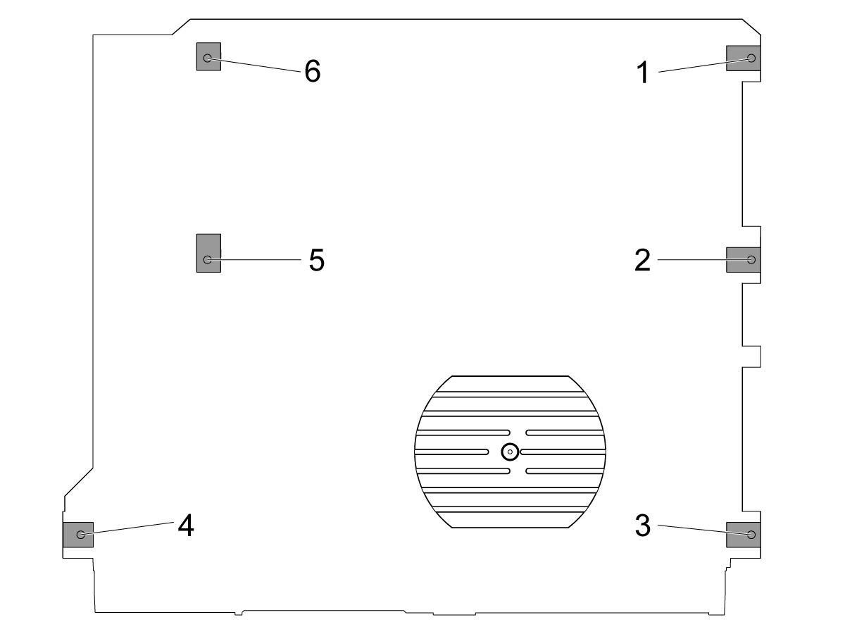
فك مسامير المستوى المتوسط [2 و5] بحيث لا تدعم أي وزن مطلقًا.

اضبط الماكينة على مسامير تسوية الركنية الأربعة مقاس 3" (76.2 مم) أعلى من مستوى سطح الأرض.

2

الضبط الدقيق لمستوى الماكينة:

أدِر مسمار التسوية رقم 4 لأعلى.

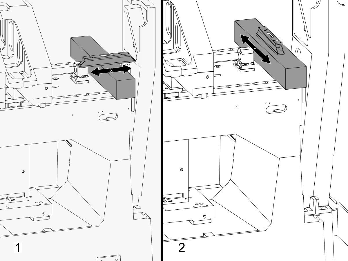
ضع الجرانيت على مستوى المؤشرات التحتية للمحور X بالقرب من دعامة محمل البرغي اللولبي للمحور X.

قم بضبط مستوى مشغل الماكينة على نحوٍ متوازي على الجزء الجرانيتي الصلب بشكلٍ موازي للمحور X.[1]

اضبط مستوى مسمار التسوية رقم 6 حتى تصبح الماكينة مستوية على المحور X.

قم بضبط مستوى مشغل الماكينة على نحوٍ متوازي على الجزء الجرانيتي الصلب في وضع متعامد مع المحور X.[2]

اضبط مسمار التسوية رقم 3 حتى يصبح مشغل الماكينة في نفس مستوى المحور Y.

أدِر مسمار التسوية رقم 4 لأسفل حتى يلامس لوحة التسوية.

3

اضبط بكرة المحور X:

قم بتجميع T-2192 مع T-2181.

حرك المحور Y إلى منتصف مسافة النقل.

ضع T-2192 على جانب عمود الدوران.

تأكد أن قراءة الفقاعة المعروضة على T-2181 تقع في النطاق المقروء.

وإذا لم تكن كذلك، فعليك فك البرغي المثبت لـ T-2192 في القاعدة المغناطيسية وتحريك المحول حسب الحاجة.

هز المحور X من جانب لآخر وقِس معدل دوران المحور X. قم بتدوين القراءات المعروضة في الوضع الرئيسي ووسط ونهاية منطقة النقل.

اضبط مسمار التسوية رقم 4 حتى لا يكون هناك أي انحراف بين القراءة في الوضع الرئيسي والقراءة عند نهاية منطقة النقل.

ملاحظة: ليس من الضروري أن تكون الفقاعة المعروضة على T-2181 في منتصف المسافة. لا يلزم سوى أن تكون في نطاق القيم المقروءة فحسب.

4

ضبط مسامير التسوية الوسطى:

أدِر مسامير التسوية الوسطى لأسفل حتى تصبح ملامسةً للوحات التسوية وبعد ذلك قم بإدارتها 45 درجة إضافية.

تحقق من بكرة المحور X. اضبط مسامير التسوية الوسطى لتصحيح استواء بكرة المحور X.

محاذاة المحور X بالمحور Y

1

قم بمحاذاة الوجه الخاص بسرج المخرطة مع حركة المحور X:

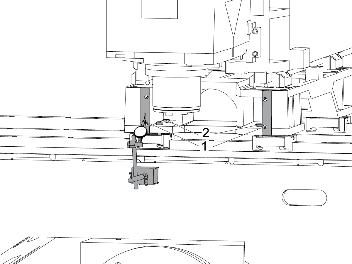
افحص سطح الماكينة بالكامل من جهة سرج المخرطة [1] عن طريق هز المحور X.

فك البراغي المثبتة لسرج المخرطة بشاحنات نقل المحور X [2] ومحاذاة وجهة السرج بحيث تكون موازيةً لحركة المحور X في نطاق 0.001" إذا لزِم الأمر.

اضبط عزم دوران المسامير. ارجع إلى  مواصفات عزم دوران المثبت من Haas.

2

قم بمحاذاة المحور Y بشكلٍ متعامد مع المحور X:

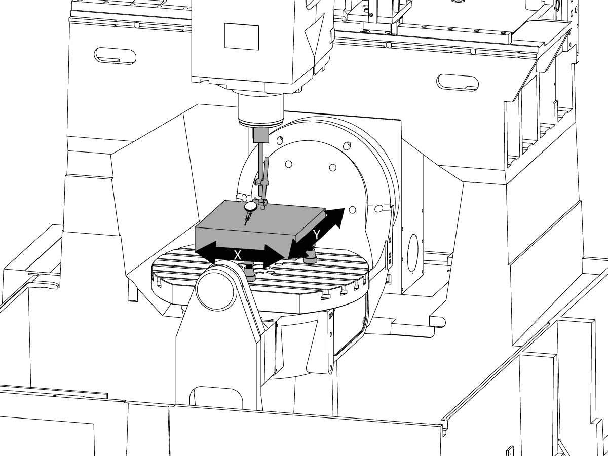
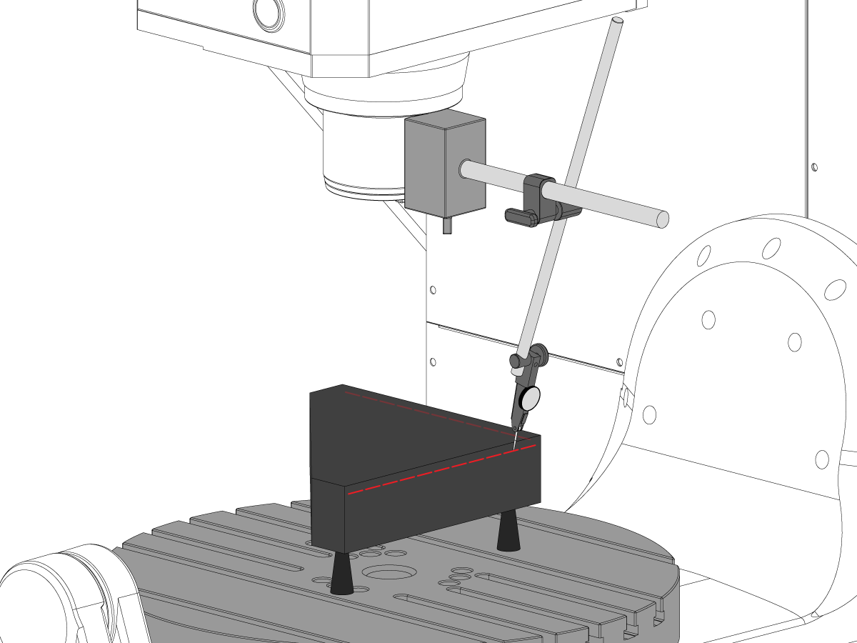
اضبط اللوحة الجرانيتية ذات الثلاث مربعات الموجودة على الجانب الأيسر من أسطوانة المحور C على مقابس مشغل الماكينة.

اضبط الجانب الخلفي من اللوحة الجرانيتية ذات الثلاث مربعات الموازية للمحور X. NTE 0.0001"/10"

اجعل الجزء العلوي من اللوحة الجرانيتية ذات الثلاث مربعات مستوية على مستوى المحورين X وY.

اضبط مقابس مشغل الماكينة حتى يصبح السطح العلوي للوحة الجرانيتية ذات الثلاث مربعات موازية للوحة X-Y NTE 0.0005".

تحقق أن الجانب الخلفي من اللوحة الجرانيتية ذات الثلاث مربعات الموازية للمحور X. NTE 0.0001"/10".

فك البراغي التي تثبت شاحنة المحور Y في سرج المخرطة وقم بمحاذاة المحور Y بشكلٍ متعامد مع المحور X. NTE 0.0005"/10"

اضبط عزم دوران المسامير. ارجع إلى  مواصفات عزم دوران المثبت من Haas.

تحقق من تعامد المحور Y على المحور X NTE 0.0005"/10" بعد إحكام ربط البراغي.

محاذاة المحور Z للوحة X-Y

1

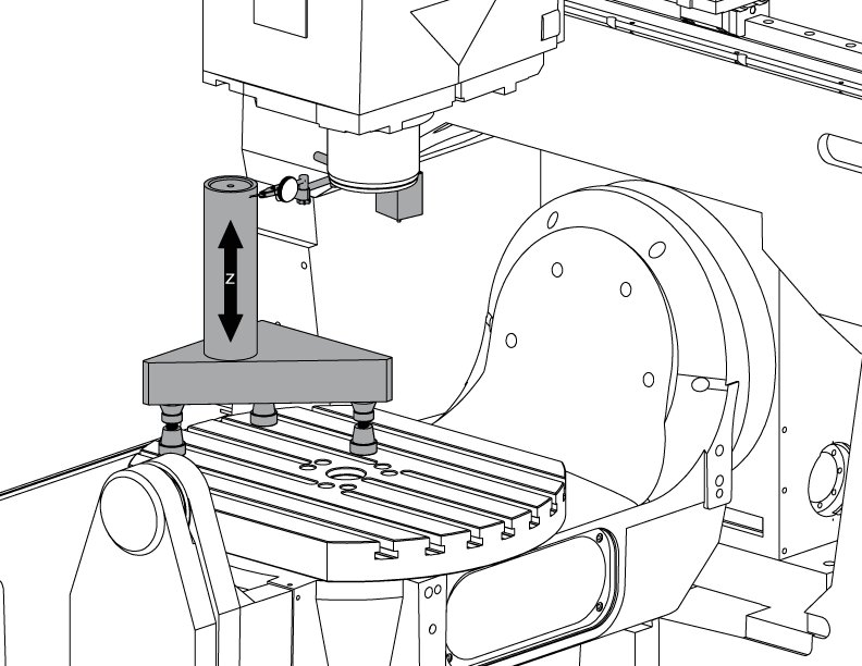
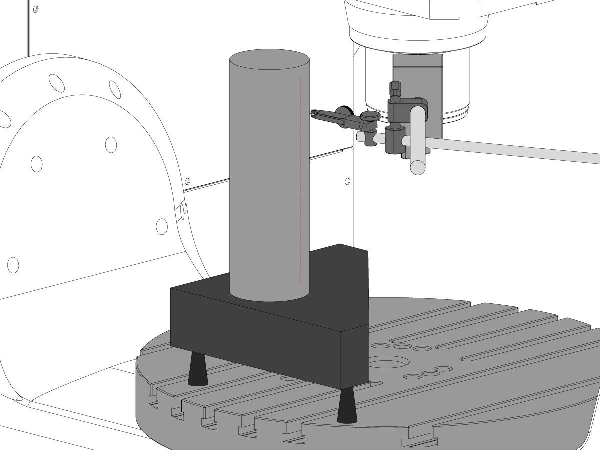
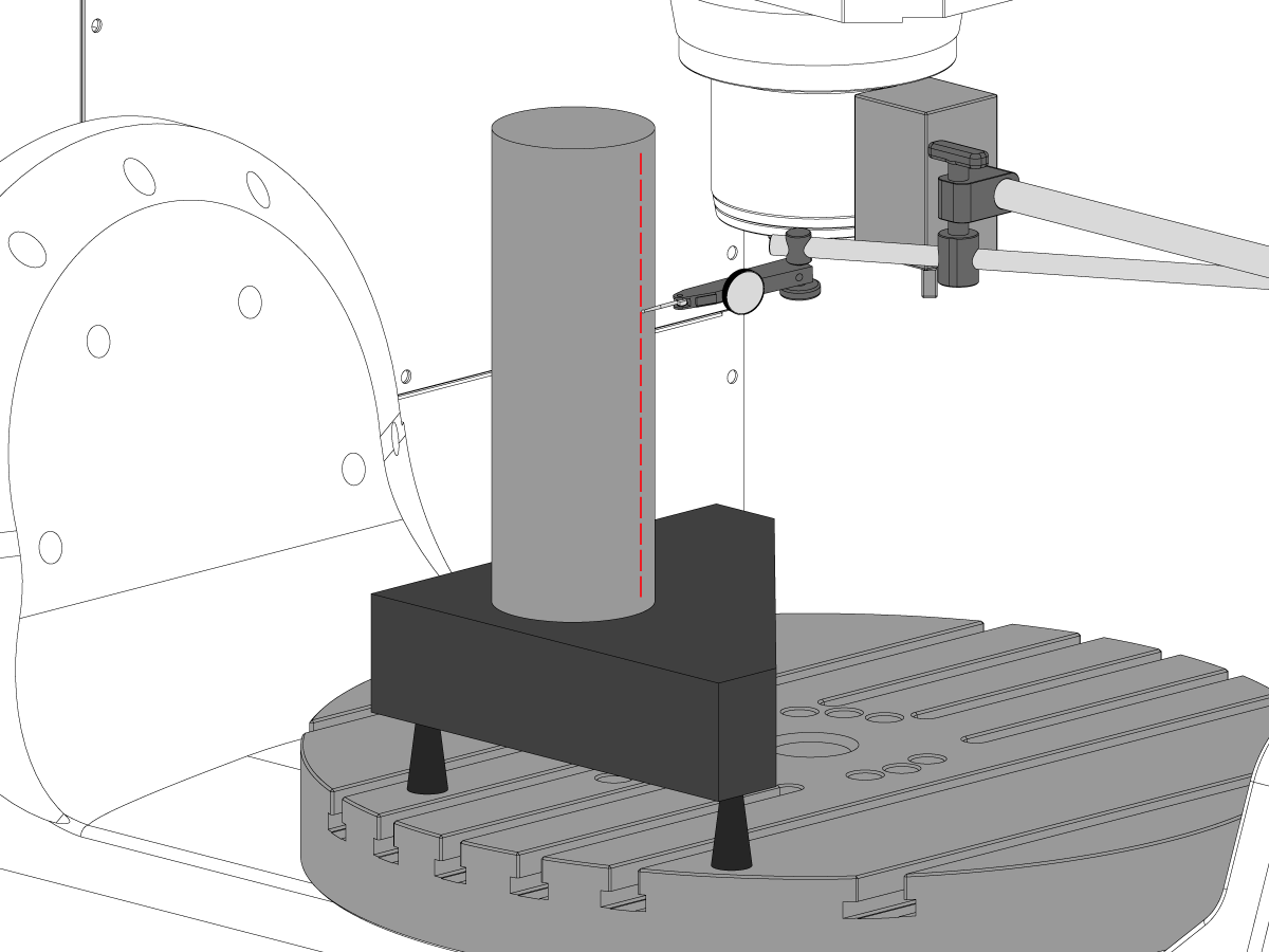
إعداد الأسطوانة.

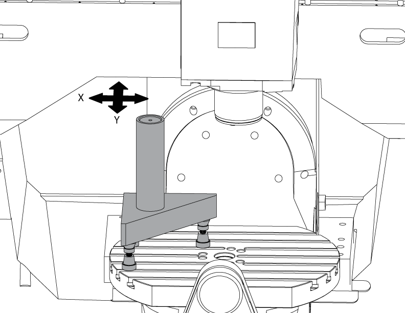
ضع أسطوانة على tri-stone كما هو موضح في الصورة.

قم بمحاذاة سطح الأسطوانة بشكلٍ موازي للوحة X-Y NTE 0.0001" عن طريق تدوير مقابس مشغل الماكينة.

هز الماكينة إلى الموضع التالي:

  • UMC-750 إلى X -7.000" وY -10.000"
  • UMC-750SS إلى X -10.000" وY-10.000"

2

قم بمحاذاة المحور Z بشكلٍ متعامد مع المحور X:

أعِد تركيب أحد البراغي الركنية العليا على شاحنات نقل المحور Z باستخدام T-2193A * لجعلها في بؤرة رأس مغزل.

يشير إلى جانب الأسطوانة بطول المحور Z.

فك البراغي المثبتة لشاحنات نقل المحور Z إلى الذراع.

قم بمحاذاة المحور Z X NTE 0.0005"/10" عن طريق أرجحة رأس مغزل من جانب لآخر.

اضبط عزم دوران المسامير. ارجع إلى  مواصفات عزم دوران المثبت من Haas.

تحقق من تعامد المحور Z على المحور X بعد إحكام ربط البراغي.

أعِد تركيب T-2193A * باستخدام البرغي عند الانتهاء من المحاذاة

*  : يُستخدم فقط في سلسلة ما قبل إعادة التمهيد. 

3

قم بمحاذاة المحور Z بشكلٍ متعامد مع المحور Y:

يشير إلى الجهة الأمامية من الأسطوانة بطول المحور Z.

ضع فلكة بين شاحنة نقل المحور Z والذراع لمحاذاة المحور Z بشكل متعامد مع المحور Y NTE 0.0005"/10".

ملاحظة: اضبط إما شاحنتي النقل العلويتين أو السفليتين بوضع رقيقة باستخدام عدد متساوٍ من الرقاقات.

اضبط عزم دوران المسامير. ارجع إلى  مواصفات عزم دوران المثبت من Haas.

تحقق من تعامد المحور Z على المحورين X وY بعد إحكام ربط البراغي.

4

قم بمحاذاة المحورين Y وZ وأحكم ربط إطارات تثبيت الصواميل الكروية:

فك البراغي المثبتة للصامولة الكروية في إطار التثبيت والبراغي المثبتة لإطار التثبيت في السبك.

حرر البراغي المثبتة للصامولة الكروية في إطار التثبيت والبراغي المثبتة لإطار التثبيت في السبك.

استخدم وظيفة قفل الزعزعة لإعادة المحور للخلف وللأمام على مستوى مسافة النقل بالكامل.

ملاحظة: يحظر استخدام العجلة اليدوية أو الحركة السريعة.

اضبط عزم دوران المسامير. ارجع إلى  مواصفات عزم دوران المثبت من Haas.

يمكن الوصول إلى إطار تثبيت صامولة المحور Y في الجزء الخلفي من الماكينة مع هز الكباس طوال المسافة حتى الانتقال إلى الواجهة الأمامية من الماكينة.

يمكن الوصول إلى إطار تثبيت صامولة المحور Z من الواجهة الأمامية للماكينة مع هز رأس عمود الدوران طوال المسافة لأسفل.

ملحوظة: يجب إزالة غطاء محرك عمود الدوران للوصول إلى إطار تثبيت صامولة المحور Z.

انقل عمود الدوران إلى اللوحة X-Y

1

إعداد اللوحة الجرانيتة:

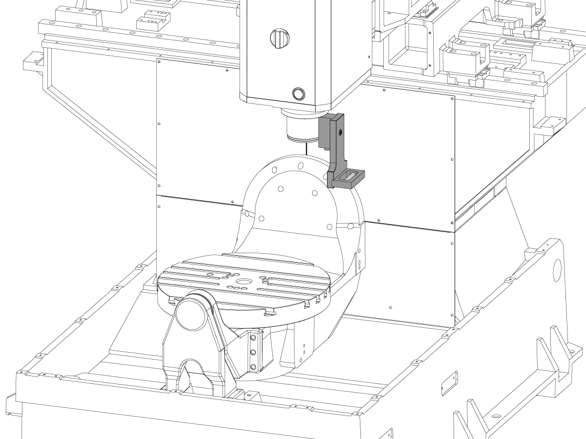
اضبط مقابس مشغل الماكينة واللوحة الجرانيتية في منتصف أسطوانة المحور C كما هو موضح في الصورة.

اجعل سطح اللوحة الجرانيتية موازيًا للوحة X-Y عن طريق ضبط ارتفاع مقابس مشغل الماكينة NTE 0.0001".

ضع عمود الدوران على مركز الأسطوانة.

2

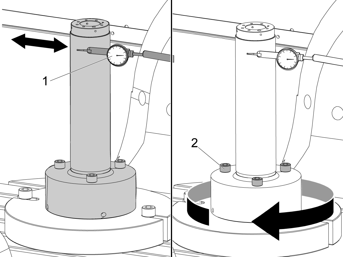
اضبط عمود الدوران في نفس مستوى المحورين X-Y:

ضع مؤشر على أسطوانة عمود الدوران.

قم بالقياس على سطح اللوحة الجرانيتية كل 90 درجة من الدوران.

فك البراغي الستة (6) المثبتة في قاعدة اللوحة المخصصة لرأس عمود الدوران.

أضِف أو أزِل رفادة من بين سبك رأس عمود الدوران ولوحة القاعدة لضبط عمود الدوران في نفس مستوى المحورين X-Y NTE 0.0005"/10".

ملحوظة: استخدم رفادات مختلفة في السمك [1] لتغيير زاوية لوحة القاعدة.

عندما يكون المسح في النطاق المحدد في المواصفات، أحكِم ربط البراغي الستة (6). ارجع إلى  مواصفات عزم دوران المثبت من Haas.

تحقق من استواء عمود الدوران بعد إحكام ربط البراغي.

محاذاة المحور B بالمحورين XYZ

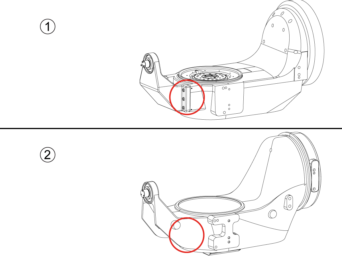
How to identify the Multi-Piece and the Unibody trunnion   

1) Multi-Piece trunnion:    UMC machines built approximetely before 11/2022 will have this configuration.

2) Unibody trunnion:    UMC machines built approximetely after 11/2022 will have this configuration.

1

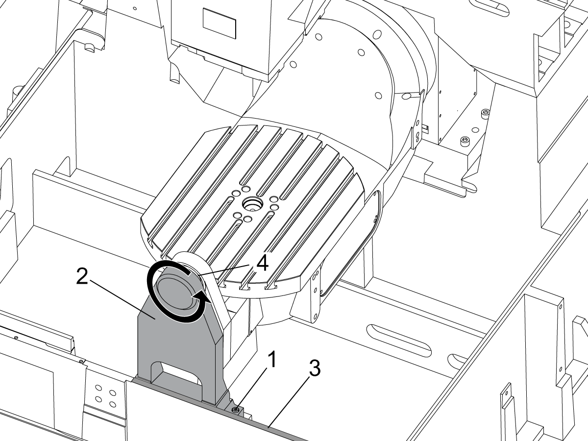
Remove the A-frame trunnion support:

Remove the bolts [1] that secure the A-frame trunnion support [2] to the base and take out the shims between A-frame support and the base.

Rotate the A-frame support [2] counter-clockwise to clear the edge of the base [3].

Pull the A-frame support off the bearings.

 Note: The A-frame support might vacuum lock on the bearings. Use the zip-tie to pry the seal [4] open.

 Caution: To lift the trunnion support, get the aid of another person. The support weighs 85 lbs (39 kg).

2

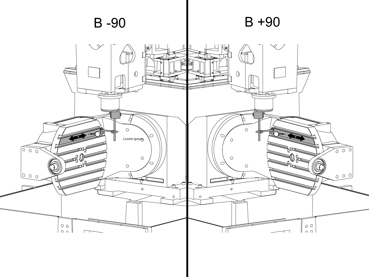
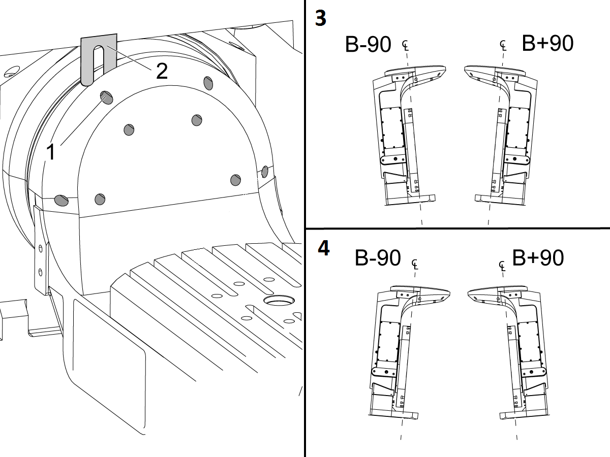
Measure the B- axis of rotation parallelism to the Y-Z plane:

For a machine with a Classic Haas Control, change Parameter 151:20 (B axis CHK TRAVL LIM) to 0.

For a machine with a Next Generation Control, change Parameter 6.021 (B axis CHK TRAVL LIM) to FALSE.

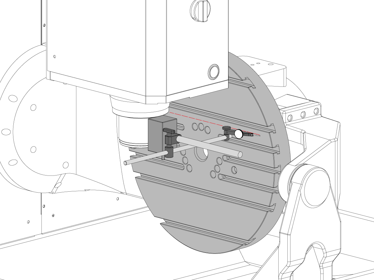
Measure the parallelism of the platter to the Y-Z plane with the B axis at 90° and then the B axis at -90° as shown in the picture.

Position the Y-Axis in the following starting position:

UMC-500: Y=0, Sweep 15”, 3rd T-Slot Land from the top.

UMC-750/1500-Duo: Y=-1.0, Sweep 18", 3rd T-Slot Land from the Top .

UMC-1250: Y=-1.0, Sweep 28", 3rd T-Slot Land from the Top.

UMC-500PP: Y=-4.0, Sweep 7".

UMC-750PP: Y=-2”, Sweep 15".

UMC-1000PP: Y=-4”, Sweep 15".

Compare the results at B 90° and B-90°. The results should be...

  • Symmetric against the Y-Z plane, positive or negative direction
  • Less than 0.0010"/20"

If the results are symmetric against Y-Z plane, and are less than 0.0010"/20 inches: Go to Step 5.

If the results are symmetric against Y-Z plane, but are more than 0.0010"/20 inches: Go to Step 4.

 Warning: If the results [3] are not symmetric against the Y-Z plane, the B axis rotary needs to be aligned: Go to Step 3.

3

Align the B axis of rotation parallel to the Y-Z plane:

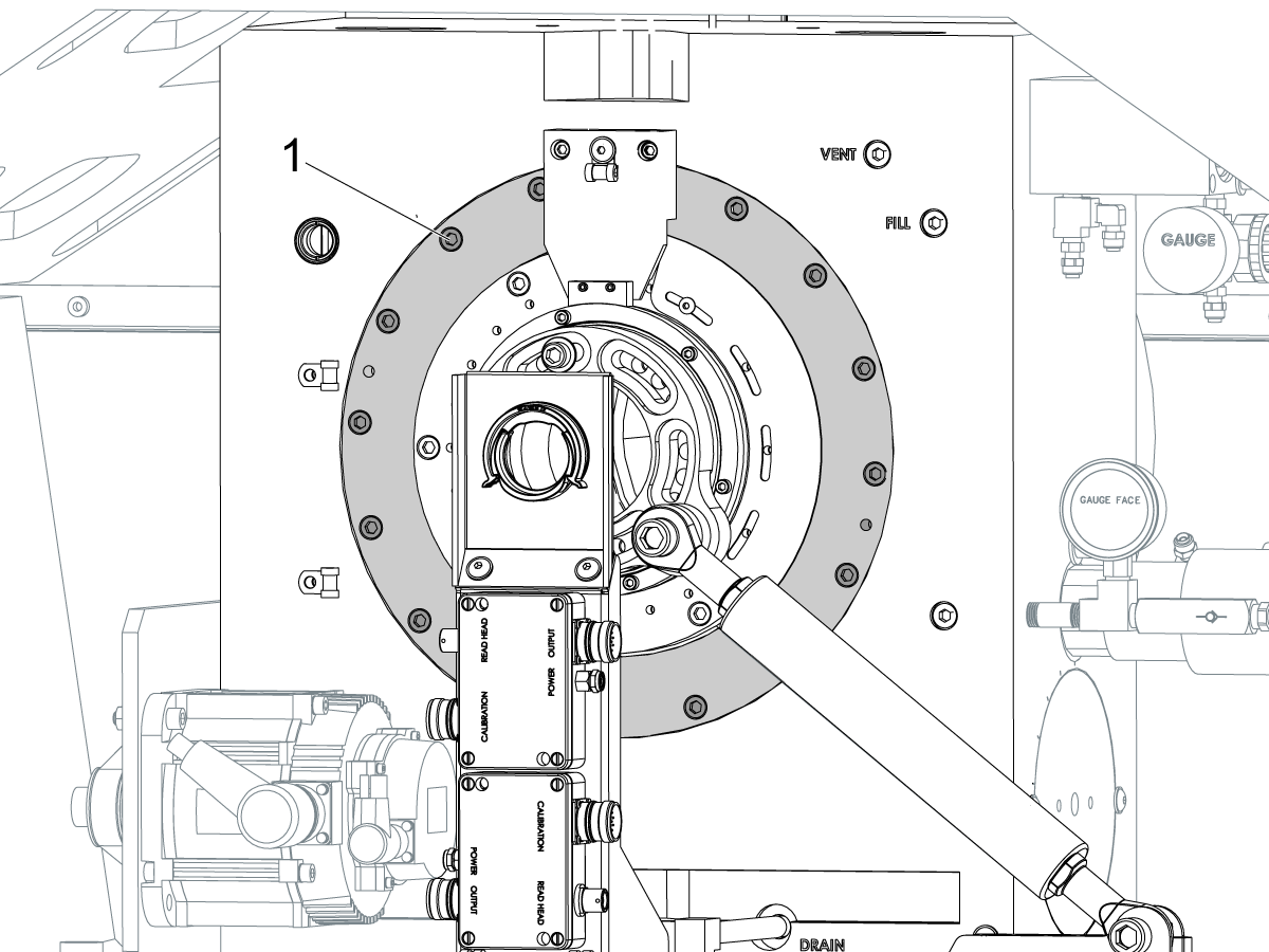
Loosen the (6) bolts [1] that secure the B axis rotary to the base casting.

 Note: Keep the bolts sufficiently snug to control the adjustments.

Adjust the front and rear setscrews [2] until the measurements taken in Step 2 are symmetric against the Y-Z plane.

Torque the (6) bolts [1]. Refer to Haas Fastener Torque Specification.

Verify the measurements in Step 2 after the bolts have been torqued.

4

Align the C Axis of rotation perpendicular to the B Axis of rotation:

Remove the bottom C-Axis access cover.

Loosen the (12) bolts [1] that hold the C Axis body to the B Axis platter face.

Reach the bottom (4) bolts through the C Axis access port.

If the B Axis is symmetric in the positive direction [4], install horseshoe shims [2] of appropriate size behind the top (2) bolts.

If the B Axis is symmetric in the negative direction [5], install horseshoe shims [2] of appropriate size behind the bottom (2) bolts.

Torque the (12) bolts to 80 Ft-lbs (108 Nm).

Cut the excessive shim material off.

Verify the measurements in Step 2 after bolts are torqued.

5

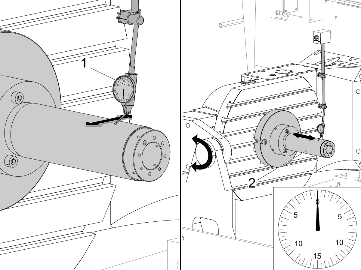
Align the trunnion support shaft co-axial with the B Axis of rotation:

Setup (2) indicators on the outer race of the trunnion support bearing [2] as shown in the picture.

Mark the spot on the outer race where one of the indicator needles is contacting the surface.

After moving the B Axis to 90° or -90° you will align the marked spot with the needle again to exclude the bearing runout error from the measurements.

Take the readings when B is at 90° and B at -90°. Compare the readings. 

 Caution: The B axis brake needs to be clamped when taking the readings.

The deviation between the results when B is at 90° and at -90° needs to be less than 0.001" on each indicator.

 Note: The indicator on the side of the bearing will measure top to bottom alignment and the indicator on the top of the bearing will measure side to side alignment.

____

For models with a multi-piece trunnion

Loosen the (6) bolts [3] on the C Axis body support. Keep the bolts sufficiently snug to control adjustment.

Adjust the (8) set screws [4] until deviation between B at 90° and B at -90° is within 0.001".

Torque the (6) bolts [2] on the C Axis body support to 80 Ft-lbs (108 Nm).

Verify the alignment after the bolts have been torqued.

____

For models with a unibody trunnion

Jog rotary to B90. Set up an indicator on the highlighted surface as shown in the lower diagram .

Rotate B-axis 180 degrees (90 to -90).

Run out (NTE 0.010” TIR).

 Caution: If the measurement exceeds the tolerance then contact support.

6

Install and shim the A-frame trunnion support:

Move the B Axis to 90°.

Setup an indicator [1] against a machined surface of the C Axis body. Set the indicator to 0.

Use plastic zip ties [2] to pry the seal open while installing the A-frame support. This lets unwanted air and grease out of the assembly.

Install the A-frame trunnion support [3] over the bearings.

Remove the cable ties.

Turn the trunnion support clockwise until it is vertical.

 Note: The weight of the A-frame support will cause the trunnion to sag. The amount of sag is measured with the indicator that was previously setup on the side of the C Axis body.

____

For multi-piece trunnions

Adjust the shims [4] between the A-frame support and the base casting to remove the sag until indicator reads 0 again.

When the indicator reading is 0, torque the (4) bolts. Refer to Haas Fastener Torque Specification.

Verify the reading after bolts are torqued. Adjust the shims again if necessary until the indicator reads 0.

____

For models with unibody trunnion

Determine the amount of shim stock [4] needed to raise the Trunnion arm so the indicator reads 0.005".

The indicator [1] value will change once the support is torqued.

With indicator still in place:

  • Torque trunnion support bolts to appropriate values.
  • Check indicator to make sure it reads between the range of

Trunnion arm raised (0.005” to  0.010”).

 Note: For unibody trunnions, the shim location may also be used to correct the C-axis to X-Y plane perpendicularity instead of shimming the saddle trucks.

 Caution: Use equal amount of shims on each side of the A-frame support. Unequal shims will cause the A-frame support to pull the trunnion to the side.

Verify the B Axis of rotation alignment to the Y-Z plane (Step 2). Loosen the bolts and tap the A-frame support side to side if necessary to correct the B axis to Y-Z plane alignment.

7

Set C-axis perpendicular to X/Y plane:

Move the axes to

UMC-750's........X= -10.5" & Y=0."

UMC-1000's......X=-17.0" & Y=-0."

Zero an indicator [1], on a Ground Block [2], 1/2" off the edge at the rear of the platter (Mag-Base on Spindle), with C at 0 Degrees

Rotate C-Axis to 180°.

Move Y axis, and ground block, in Y Axis negative direction until you are 1/2" away from platter edge, and take the perpendicularity measurement

Adjust the shims until the average error is within 0.0005" end to end.

 Note: For unibody trunnions, the shim location under the bearing support may also be used to correct the C-axis to X-Y plane perpendicularity instead of shimming the saddle truck.

Caution: Shim either two front trucks or two rear trucks with the equal shim.

Note: Shim one truck at the time to maintain the X to Y squareness.

Verify the measurements after all bolts are torqued.

Verify the X to Y alignment in Step 2.

8

Set the tool change offsets:

B-axis tool change offset [1]

For Classic Haas Controls, change Parameter 213. 

For Next Generation Controls, go to: Settings>Rotary Tab>Highlight the rotary and press [INSERT], or change Parameter 6.078 (B TOOL CHANGE OFFSET) to set the trunnion (B Axis) parallel to the X Axis.

For models with multipiece trunnion

(NTE 0.001/10"; NTE 0.0020" overall)

For models with unibody trunnion

(NTE 0.0005/10"; NTE 0.0010" overall)

___

C-axis tool change offset [2]

For Classic Haas Controls change Parameter 523.

For Next Generation Control go to: Settings>Rotary Tab> Highlight the rotary and press [INSERT], or change Parameter 7.078 (C TOOL CHANGE OFFSET) to set the table T-slot (C Axis) parallel to the X Axis

For models with multipiece trunnion

(NTE 0.001/10"; NTE 0.0020" overall)

For models with unibody trunnion

(NTE 0.0005/10"; NTE 0.0010" overall)

9

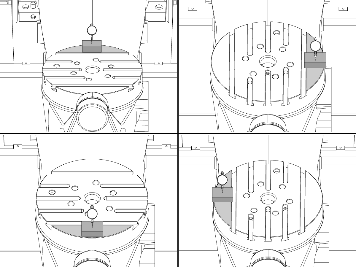
Check C-axis perpendicularity to X/Y plane:

Align the indicator centered over the C-axis bore with the Y-axis at -10.

Jog positive in the Y-axis and align the indicator over the center of the last section of the platter and make a mark at this spot with a washable marker.

Insert 1-2-3 block as shown and set the indicator to zero.

Remove the block and rotate the platter 90 degrees, following the marked spot with the indicator.

Insert block back between the indicator and platter. Note reading.

Repeat the previous two steps, taking readings with the platter at 180, 270 and 360 degrees.

Multi-piece trunnion:  (NTE 0.0005")

Unibody trunnion: (NTE 0.001")

10

Measure the intersection of the B and C axis:

Follow the linked instruction manual to complete this step.

B-Axis and C-Axis intersection Adjustment

11

Align the B-Axis brake disk:

 Note: Do not do this step if you are working on a SS machine.

Operate this code in MDI mode to unclamp the brake:

M11;

Loosen all of the brake disc bolts [1] and torque them to 5 Ft-lbs (7 Nm).

Operate this code in MDI mode to clamp the brake:

M10;

Wait 10 seconds.

Torque the bolts. Refer to Haas Fastener Torque Specifications.

تعيين المعلمة/إعادة الضبط على قيم المصنع

اضبط المعلمة 1314 الخاصة بإعداد CHC / 254 وأعِد ضبط القيمة NGC على القيمة المحددة في ضبط المصنع .(قم بتوصيل التيار الكهربي بالماكينة بعد تغيير القيمة.)

قم بمحاذاة ومعايرة WIPS. نظام Wireless Intuitive Probe System (WIPS) - المعايرة

ضبط نقاط الصفر للطاولة الدوارة بالماكينة. 

  • إعدادات إزاحات UMC-750 - MRZP WIPS - CHC
  • إعدادات إزاحات UMC-750 - MRZP WIPS - NGC

املأ  تقرير الفحص الشامل:

  • تقرير فحص EA0420 UMC-500
  • تقرير فحص EA0373 UMC-750
  • تقرير فحص EA0418 UMC-1000

احتفظ بنسخة من تقرير الفحص مع الماكينة.

إذا استبدلت مجموعة المحورين B وC، فقم بعمل  UMC-750 - تداخل المحور B والمحور C - المحاذاة

8.2 المحاذاة - مناطق المؤشر

Recently Updated

مناطق مؤشر محاذاة UMC


AD0490

المناطق الدلالية

1

درفيل المحور X

  • قم أولاً بتوصيل الأداة T-2192 بجانب المغزل.
  • بالنسبة لقياس X-Roll، احمل مواضع المحور Y وZ التالية:
    • UMC 500 (Y,Z): -8, -8
    • UMC 750 (Y,Z): -10, -10
    • UMC 1000 (Y,Z): -12, -12
  • قياس لفافة المحور X (NTE 0.0005 " / 10")


2

توازي المحور Z مع المحور Y

  • اجعل الخلوص صفرًا للمحاور B و C.
  • قم بقياس انحراف الطبق في المحور (NTE: 0.0008" / 10"; 0.0012" / 15")
  • ثم قم بقياس نفس هذا السطح باستخدام المحور B عند كل من -90 درجة و+90 درجة  (NTE: 0.0008 " / 10"; 0.0012 " / 15")
  • بالنسبة إلى UMC 500 و750، قم بقياس الطول الكامل للطبق
  • بالنسبة إلى UMC 1000، إزاحة 2 بوصة من حافة الطبق ثم القياس عبر 20 بوصة

3

تعامد المحور

Y مع المحور X

  • استخدم براغي جاك لجعل السطح العلوي للجرانيت موازيًا للسطح XY (NTE: 0.0002)"
  • بعد ذلك، تحقق مما إذا كانت Y مربعة على X (NTE 0.0005 " / 10")

4

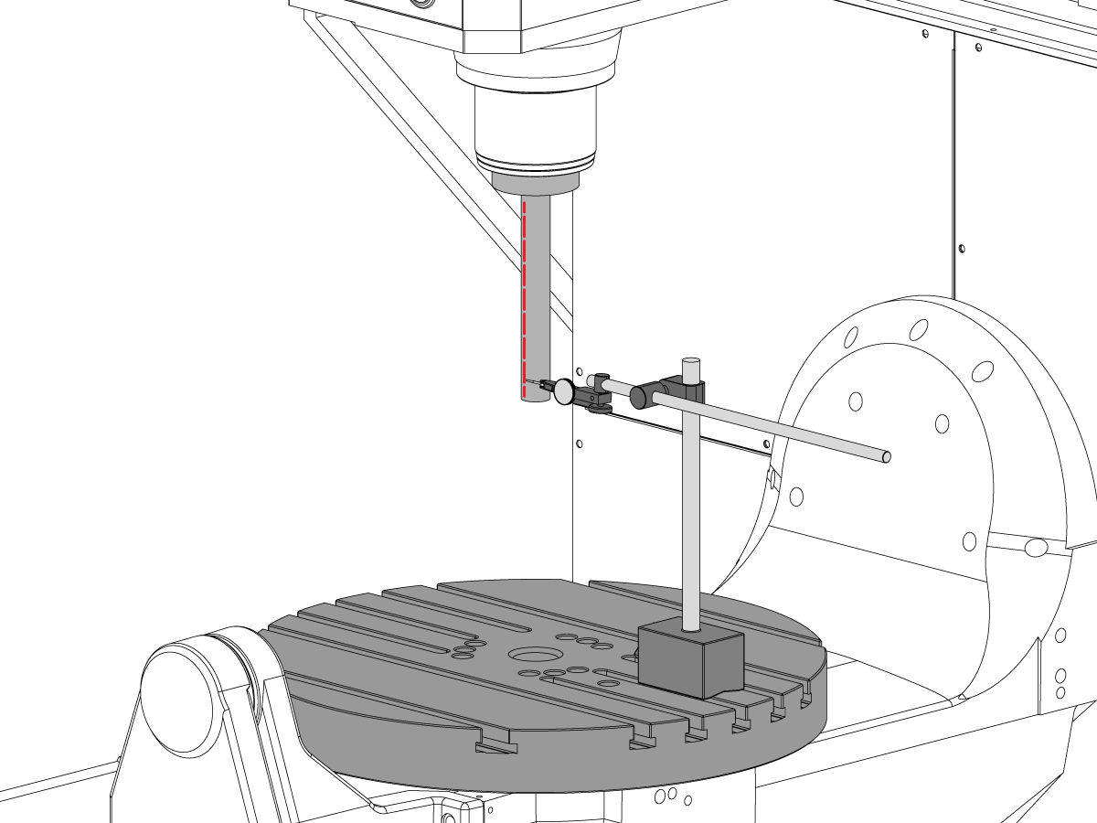
تعامد المحور X على المحور Z

  • ضع الجرانيت وأسطوانة الدقة على الطبق في الاتجاه الموضح
  • استخدم براغي جاك لجعل السطح العلوي موازيًا للأسطوانة XY (NTE: 0.0002)"
  • مواقع المغزل XY لهذه الخطوة:
    • UMC 500, X = -6, Y = -8
    • UMC 750, X = -10, Y = -10
    • UMC 1000, X = -17, Y = -12
  • موضع بداية Z لهذا القياس:
    • UMC 500، Zبدء = Z علوي – 2 بوصة
    • UMC 750، Zبدء = Z علوي – 5 بوصة
    • UMC 1000، Zبدء = Z علوي – 7 بوصة
  • Zعلويهو حد انتقال المحور Z في الاتجاه الموجب (أعلى)
  • من Zبدء، قم بقياس 10 بوصة لأسفل على طول الأسطوانة

5

تعامد المحور Y على المحور Z:

  • ضع الجرانيت وأسطوانة الدقة على الطبق في الاتجاه الموضح
  • استخدم براغي جاك لجعل السطح العلوي موازيًا للأسطوانة XY (NTE: 0.0002)"
  • مواقع المغزل XY لهذه الخطوة:
    • UMC 500, X = -6, Y = -8
    • UMC 750, X = -10, Y = -10
    • UMC 1000, X = -17, Y = -12
  • موضع بداية Z لهذا القياس:
    • UMC 500، بداية Z = Z علوي  – 2”
    • UMC 750, بداية Z = Z علوي  – 5”
    • UMC 1000, بداية Z = Z علوي  – 7”
  • Z علوي هو حد انتقال المحور Z في الاتجاه الموجب (أعلى)
  • من بداية Z، قم بقياس 10 بوصة لأسفل على طول الأسطوانة

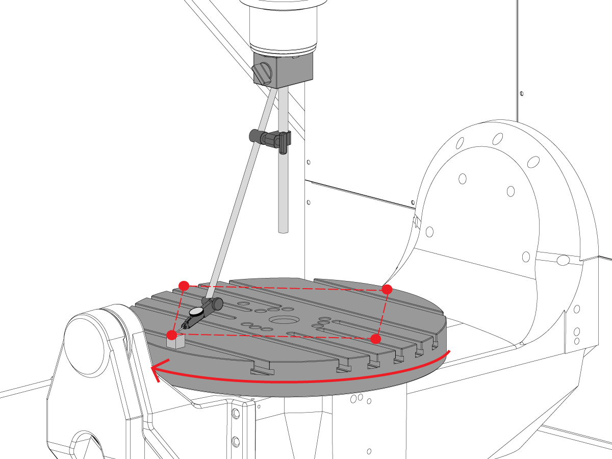
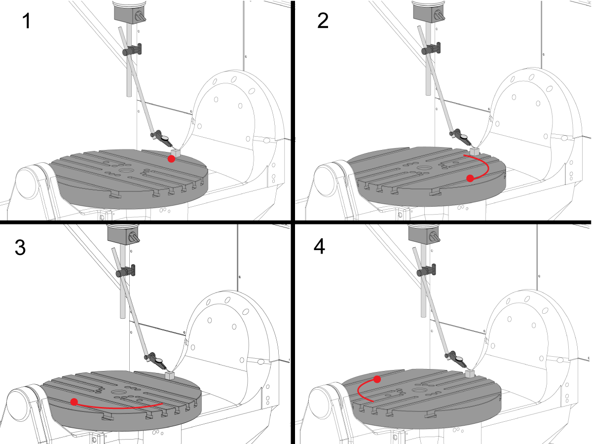
6

تعامد المحور

C على المستوى XY

  • أعد وضع القاعدة المغناطيسية على المغزل بحيث لا يمكن تدويرها مع المغزل.
  • ضع كتلة القياس الدقيقة على حافة الطبق في موضع الساعة 12. 
  • قم بتصفير طرف المؤشر على كتلة المقياس في هذا الوضع.
  • قم بتدوير المحور C   90 درجة 
  • بعد ذلك، قم بتشغيل المغزل في المحور X وY لمتابعة كتلة القياس وأخذ قياس لنفس النقطة على الطبق. يجب ألا يحدث دوران لالمغزل
  • كرر ذلك مرتين إضافيتين لإجمالي 4 مواضع، بزاوية 90 درجة، عند حافة المنصة كما هو موضح. 
  • يحدد الفرق بين قياسات موقع الساعة 12 و6 الاستواء على طول المحور X (NTE 0.0005
  • )"
  • يحدد الفرق بين قياسات موقع الساعة 3 و9 الاستواء على  طول المحور Y (NTE 0.0005")

7

تجاوز وجه الطبق

ملاحظة: فرامل المحور C في وضع إيقاف التشغيل لهذه الخطوة

  • ضع كتلة القياس الدقيقة على حافة الطبق في موضع الساعة 12. 
  • قم بتصفير طرف المؤشر على كتلة المقياس في هذا الوضع.
  • قم بتدوير المحور C بزاوية 90 درجة  ولكن، مع إبقاء كتلة القياس في موضع الساعة 12
  • قم بإجراء قياس من أعلى كتلة المقياس
  • كرر ذلك مرتين إضافيتين لإجمالي 4 مواضع، بزاوية 90 درجة، عند حافة المنصة كما هو موضح. 
  • لاحظ إجمالي التجاوز المشار إليه. (NTE 0.001")

8

توازي سطح الطبق مع المستوى XY

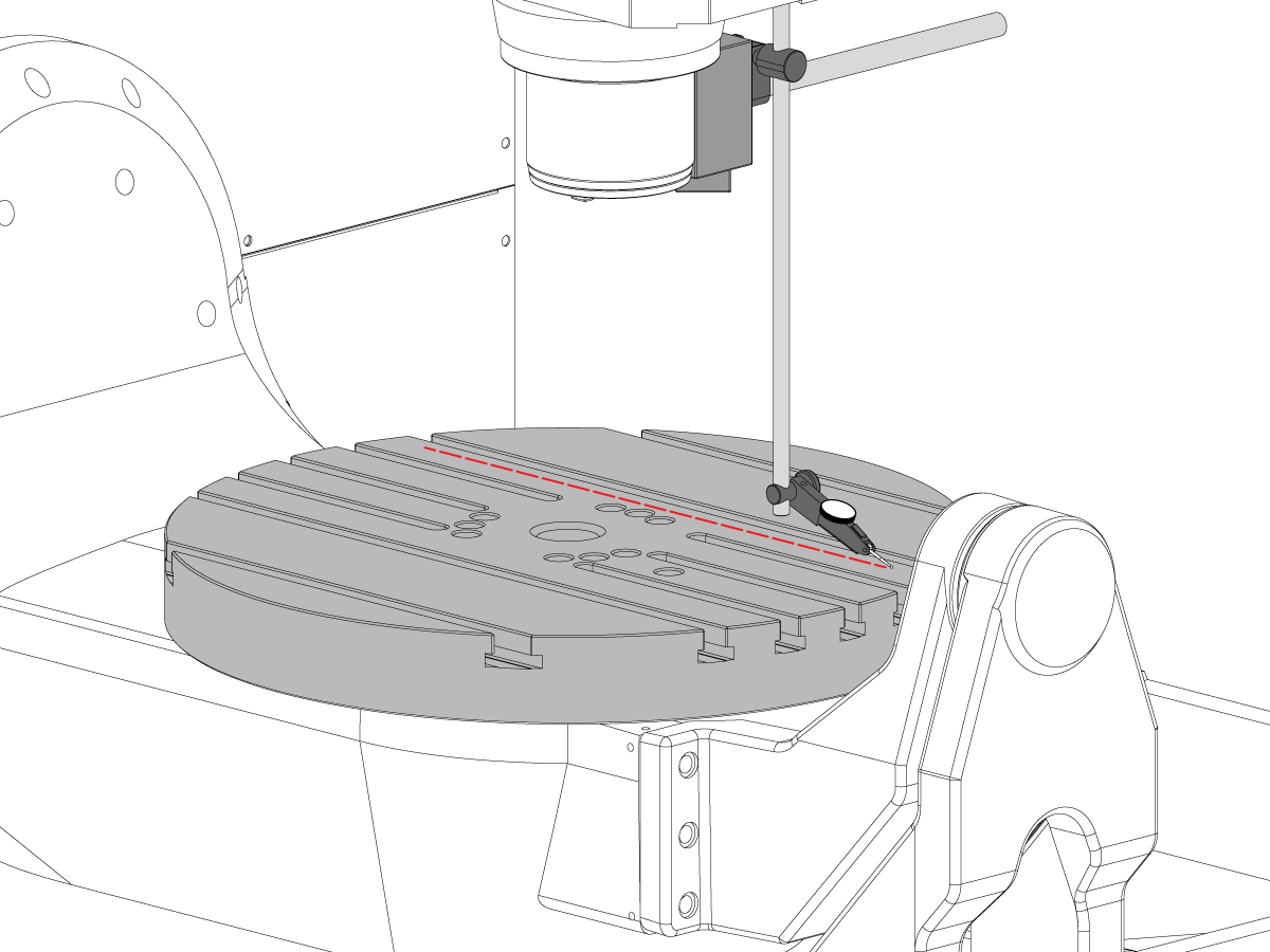
  • قم بإرجاع المحور C إلى الصفر بحيث تسير الفتحات T بالتوازي مع المحور X
  • ضع طرف المؤشر على الطبق وقم بالركض في المحور X على طول الطبق لإيجاد التوازي مع طبق المحور X (NTE 0.001 بوصة / 10"؛ 0.0015 " / 15")
  • ثم قم بالدفع في المحور Y على طول الطبق لإيجاد التوازي مع طبق المحور Y (NTE 0.001 بوصة / 10"؛ 0.0015 " / 15")

9

انحراف المغزل

  • قم بتوسيط المغزل فوق تجويف المحور C.
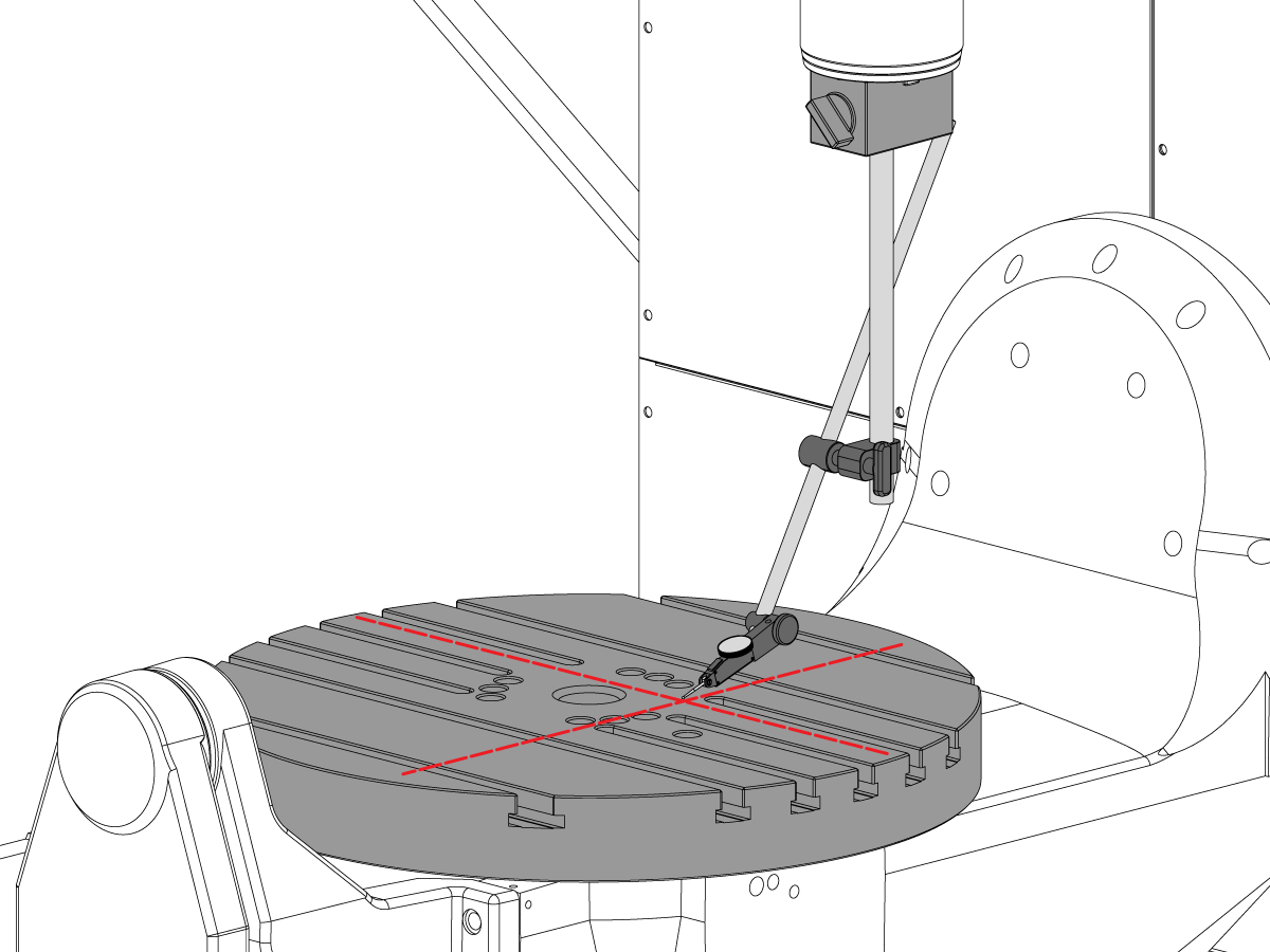
  • ضع القاعدة المغناطيسية على المنضدة وأدخل شريط الاختبار.
  • افحص انحراف المغزل عند قاعدة عمود الاختبار (NTE 0.0005 " TIR)
  • افحص انحراف المغزل 6 بوصة"عند قاعدة عمود الاختبار (NTE 0.001" TIR)

10

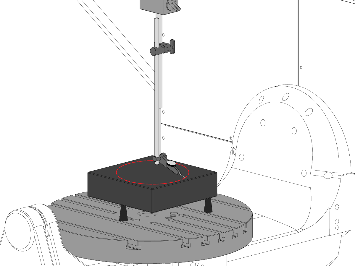
التوازي بين الخط المركزي للمغزل والمحور Z:

  • استخدم براغي جاك لجعل الجرانيت موازيًا للسطح XY (NTE: 0.0002)"
  • قم بتوسيط المغزل فوق تجويف طبق المحور C.
  • امسح في دائرة قطرها 10 "بوصة
  • سَجِل XZ TIR  (NTE 0.0005")
  • سَجِل YZ TIR  (NTE 0.0005")

11

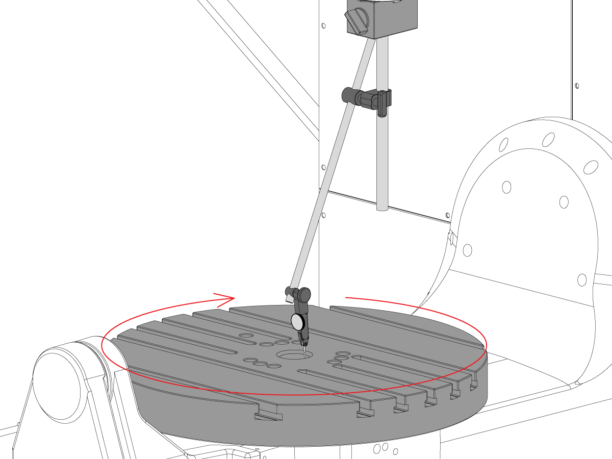
مركزية تجويف المحور C

  • ضع المؤشر كما هو موضح وادفع المحور C 360 درجة
  • سجل TIR لتجويف الدقة (NTE 0.002")

12

إزاحات نقطة الصفر الدوارة للماكينة.

  • استخدم برنامج ماكرو VQC ونظام الفحص للتحقق من قيم معلمات Coldfire أو إعدادات NGC الموضحة أدناه:
    • 255 - إزاحة MRZP X
    • 256 - إزاحة MRZP Y
    • 257 - إزاحة MRZP Z
    • 254 - مسافة نقطة المركز الدوارة لعدد 5 محاور
  • للحصول على تعليمات MRZP كاملة، يُرجى الاطلاع على   إجراء إعداد إزاحة WIPS من Haas MRZP

8.3 الهندسة - استكشاف الأعطال وإصلاحها

Recently Updated

UMC - الأعطال الهندسية - دليل استكشاف الأعطال وإصلاحها


TG0151

نظرة عامة

قبل استكشاف مشكلة دقة أو مشكلة هندسية بماكينة UMC-750، يجب أن يكون الفني متمتعًا بفهم شامل للأساسيات التالية:

  • كيفية ضبط مستوى ومحاذاة المحاور الدوارة لـ UMC
  • كيفية إعادة محاذاة كل محاور الماكينة
  • كيفية إجراء معايرة MRZP وفهم شامل بماهية المعلمات المرتبطة بها، وتأثيرها على الماكينة
  • فهم لإمكانيات دقة الماكينات والقدرة على التفكير على الرغم من المشكلات الهندسية
  • محاذاة تقاطع المحور B إلى C

يجب معالجة للمشكلات الهندسية ومشكلات الدقة في ماكينات UMC-750 بشكل منهجي وبتسلسل ملائم. ينبغي الالتزام بالمعلومات التالية بدقة بالغة واتباعها في ترتيب تسلسلي.

من المهم للغاية قبل إجراء أي تقييم أو ضبط على هندسة الماكينة أن يتم فحص الماكينة للتأكد من المستوى الملائم ومحاذاة المحاور الدوارة مع الماكينة

يمكن أن تُعزى العديد من الأخطاء إلى معاناة الماكينة من اصطدام أو مشكلات إما في تطبيقات الأدوات أو مشكلات البرمجة. لا تحاول تغيير هندسة الماكينة بدون إجراء فحص كامل للمستوى الكلي للماكينات وهندستها وفقًا لتقرير الفحص. يشمل ذلك فحص Machine Rotary Zero Point (MRZP).

في حالة حدوث اصطدام توجد 4 وصلات انزلاق بالماكينة. هذه المناطق هي من رأس عمود الدوران إلى الذراع، ومن الذراع إلى سرج المخرطة، ومن سرج المخرطة إلى الجسر، ومن مرتكز الدوران إلى دعامة مرتكز الدوران.

 ملاحظة: ينبغي ألا يتم بأي حال من الأحوال تزويد هذه الوصلات برفادات. ينبغي ألا يؤدي اصطدام الماكينة مطلقًا إلى تغيير مقدار الرفادات المطلوبة في الماكينة من إعدادات المصنع.

من المهم تذكر أن الدقة الخطية للماكينة تبلغ 0.0004/10" والدقة الزاوية +/- 15 قوس/ثانية. يمكن إضافة حدود التفاوت هذه بسرعة.

ينبغي بذل كل جهد لتحديد ما إذا كان تطبيق الماكينة معقولاً ويقع ضمن قدرة الماكينة وأدواتها وتركيباتها.

تقييم حالة الماكينة

حدد ما إذا كانت الماكينة قد تعرضت للاصطدام من قبل. راجع تاريخ الإنذارات؛ وابحث عن تلف مادي بالألواح المعدنية والطاولة ورأس عمود الدوران، وغيرها. مهما كان حجم التصادم "ضئيلاً"، فسوف يؤثر على هندسة الماكينة. في حالة تعرض الماكينة للاصطدام، يجب إجراء فحص كامل لهندسة الماكينة

قم بتقييم الحالة الكلية لتركيب الجزء وحالة أدوات القطع.

احصل على تقرير أخطاء ونسخ احتياطي كامل للماكينة.

تحقق من مستوى الماكينة وهندستها

تحقق من أن الماكينة في وضع مستوي ومن محاذاة المحور الدوار مع الماكينة

 ملاحظة: لا تحاول إجراء أي عمليات ضبط على هندسة الماكينة باستثناء ضبط قاعدة التسوية في هذا الوقت.

إذا كانت الماكينة غير مستوية أو الدوار غير متحاذي، أعد ضبط المستوى ومحاذاة الدوار.

قم بإجراء فحص كامل للهندسة مع ملاحظة حجم واتجاه أي أخطاء بكل محور.

قم بتحليل تقرير الفحص.

يلزم إعادة محاذاة الماكينة إذا كانت أي من أقسام تقرير الفحص خارج حدود التفاوت.

مراجعة التطبيق

اجمع المعلومات التالية حول الجزء وجهاز إمساك الشغلة والأدوات:

  • ما هي الميزات التي تقع خارج حدود التفاوت وحجم واتجاه الخطأ
  • هل تم تشكيل الجزء باستخدام المحور 5 أم المحور 3+2 أم المحور 3؟
  • مراجعة الجزء وأسلوب التشكيل
  • هل يمكن الحد من أي من أخطاء الدقة في الجزء من خلال تغيير أسلوب التشكيل؟
  • هي المشكلة هي مشكلة إمكانية تكرار أم مشكلة في الحجم أم مشكلة في الهندسة؟
  • هل البرنامج يستخدم TCPC أم DWO؟
  • هل هناك أي قيم في جداول التعويض؟

8.4 التطبيقات - استكشاف الأعطال وإصلاحها

Recently Updated

UMC - الاستخدامات - دليل استكشاف الأعطال وإصلاحها


TG0150

كيفية الوصول

للحصول على دليل استكشاف الأعطال وإصلاحها لتطبيقات UMC:

اتبع هذا الرابط المستندات والبرامج | HBC

أو

سجّل الدخول إلى HBC.HAASCNC.COM

ملاحظة: يمكن تسجيل الدخول إلى هذه المواقع فقط بواسطة فني خدمة معتمد من Haas. 

حدد علامة التبويب Service (الخدمة).

أسفل Utilities (الأدوات)، حدد Documents and Software (الوثائق والبرنامج).

حدد مجلد التطبيقات.

8.5 UMC-750 - قائمة فحص طقم السندة

Recently Updated

UMC-750 - قائمة فحص طقم الرفادة


AD0131

مقدمة

هذه هي قائمة فحص طقم الرفادة للمجموعة التالية:

  • 93-2236 LOANER، طقم الرفادة للماكينة UMC-750

قائمة الفحص: الرفادة-المباعد-العمود

السماكة رقم القطعة الكمية في الطقم المستخدم
.02100 20-9358A 2  
0.2105 20-9359A 2  
.02110 20-9383A 2  
0.2115 20-9365A 2  
0.2120 20-9384A 2  
0.2125 20-9385A 2  
0.2130 20-9368A 2  
0.2135 20-9369A 2  
0.2140 20-9386A 2  
0.2145 20-9371A 2  
0.2150 20-9372A 2  
0.2155 20-9387A 2  
0.2160 20-9374A 2  
0.2165 20-9375A 2  
0.2170 20-9376A 2  
0.2175 20-9377A 2  
0.2180 20-9378A 2  
0.2185 20-9379A 2  
0.2190 20-9380A 2  
0.2195 20-9381A 2  
0.2200 20-9382A 2  

ملاحظة: مالكو الأطقم فقط: يجب تحديد سُمك الرفادة عند طلب بدائل. على سبيل المثال، 20-9382 0.2145

قائمة الفحص: رفادة على شكل حدوة الحصان

السماكة رقم القطعة الكمية في الطقم المستخدم
0.0010 59-0240 2  
0.0020 59-0241 2  
0.0030 59-0242 2  

قائمة الفحص: الرفادة-المباعد-العمود-كبيرة

السماكة رقم القطعة الكمية في الطقم المستخدم
0.2130 20-6282A 2  
0.2135 20-6283A 2  
0.2140 20-6284A 2  
0.2145 20-6285A 2  
0.2150 20-6286A 2  
0.2155 20-6287A 2  
0.2160 20-6288A 2  
0.2165 20-6289A 2  
0.2170 20-6290A
2  
0.2175 20-6291A 2  
0.2180 20-6294A 2  
0.2185 20-6295A 2  
0.2190 20-6292A 2  
0.2195 20-6293A 2  
0.2200 20-6296A 2  
0.2205 20-6297A 2  
0.2210 20-6277A 2  
0.2215 20-6279A 2  
0.2220 20-6278A 2  
0.2225 20-6298A 2  
0.2230 20-6281A 2  

ملاحظة: مالكو الأطقم فقط: يجب تحديد سُمك الرفادة عند طلب بدائل. على سبيل المثال، 20-6290A 0.2080

سجِّل أي الرفادات تم فكها من العدة في العمود المستخدم.

أعد قائمة التحقق مع طقم الرفادة.

أعد الرفادة الأصلية في الصندوق.

8.6 B/C - تقاطع المحور - المحاذاة

مقدمة

يوضح هذا الإجراء كيفية قياس ومحاذاة تقاطع المحورين B و C.  قبل محاولة القيام بهذا الإجراء تأكد من أن الماكينة مستوية حسب الإجراء تسوية UMC-750.

ستحتاج إلى محاذاة المحورين B و C وبعد ذلك إما أن:

  • تستبدل المحورين B و C
  • أو تكمل تقرير تفتيش UMC وتعثر على المشكلة

يحدد بد مركز دوار المحور 5 الاختلاف بين مراكز دوارات الدوران: نقطة الصفر لدوارة الماكينة للمحور C (MRZP) ونقطة الصفر لدوارة الماكينة للمحور B في المحور X.

من الممكن عندم وجود اختلاف بين نقطة الصفر لدوارة الماكينة للمحور C والمحور B.

  • وحدة التحكم الكلاسيكية من Haas (CHC): المعلمة 1314 - Rotary Axes Center Deviation in X
  • التحكم في الجيل التالي (NGC): الإعداد 254 - 5 Axis Rotary Center Distance

ستحتاج إلى الأدوات التالية:

  • T-2195A UMC Aligment Bar Adapter
  • T-2113 Alignment bar
  • مسدس حراري وقفازات مقاومة للحرارة

محاذاة المحور B بالمحاور XYZ

How to identify the Multi-Piece and the Unibody trunnion   

1) Multi-Piece trunnion:    UMC machines built approximetely before 11/2022 will have this configuration.

2) Unibody trunnion:    UMC machines built approximetely after 11/2022 will have this configuration.

1

Remove the A-frame trunnion support:

Remove the bolts [1] that secure the A-frame trunnion support [2] to the base and take out the shims between A-frame support and the base.

Rotate the A-frame support [2] counter-clockwise to clear the edge of the base [3].

Pull the A-frame support off the bearings.

 Note: The A-frame support might vacuum lock on the bearings. Use the zip-tie to pry the seal [4] open.

 Caution: To lift the trunnion support, get the aid of another person. The support weighs 85 lbs (39 kg).

2

Measure the B- axis of rotation parallelism to the Y-Z plane:

For a machine with a Classic Haas Control, change Parameter 151:20 (B axis CHK TRAVL LIM) to 0.

For a machine with a Next Generation Control, change Parameter 6.021 (B axis CHK TRAVL LIM) to FALSE.

Measure the parallelism of the platter to the Y-Z plane with the B axis at 90° and then the B axis at -90° as shown in the picture.

Position the Y-Axis in the following starting position:

UMC-500: Y=0, Sweep 15”, 3rd T-Slot Land from the top.

UMC-750/1500-Duo: Y=-1.0, Sweep 18", 3rd T-Slot Land from the Top .

UMC-1250: Y=-1.0, Sweep 28", 3rd T-Slot Land from the Top.

UMC-500PP: Y=-4.0, Sweep 7".

UMC-750PP: Y=-2”, Sweep 15".

UMC-1000PP: Y=-4”, Sweep 15".

Compare the results at B 90° and B-90°. The results should be...

  • Symmetric against the Y-Z plane, positive or negative direction
  • Less than 0.0010"/20"

If the results are symmetric against Y-Z plane, and are less than 0.0010"/20 inches: Go to Step 5.

If the results are symmetric against Y-Z plane, but are more than 0.0010"/20 inches: Go to Step 4.

 Warning: If the results [3] are not symmetric against the Y-Z plane, the B axis rotary needs to be aligned: Go to Step 3.

3

Align the B axis of rotation parallel to the Y-Z plane:

Loosen the (6) bolts [1] that secure the B axis rotary to the base casting.

 Note: Keep the bolts sufficiently snug to control the adjustments.

Adjust the front and rear setscrews [2] until the measurements taken in Step 2 are symmetric against the Y-Z plane.

Torque the (6) bolts [1]. Refer to Haas Fastener Torque Specification.

Verify the measurements in Step 2 after the bolts have been torqued.

4

Align the C Axis of rotation perpendicular to the B Axis of rotation:

Remove the bottom C-Axis access cover.

Loosen the (12) bolts [1] that hold the C Axis body to the B Axis platter face.

Reach the bottom (4) bolts through the C Axis access port.

If the B Axis is symmetric in the positive direction [4], install horseshoe shims [2] of appropriate size behind the top (2) bolts.

If the B Axis is symmetric in the negative direction [5], install horseshoe shims [2] of appropriate size behind the bottom (2) bolts.

Torque the (12) bolts to 80 Ft-lbs (108 Nm).

Cut the excessive shim material off.

Verify the measurements in Step 2 after bolts are torqued.

5

Align the trunnion support shaft co-axial with the B Axis of rotation:

Setup (2) indicators on the outer race of the trunnion support bearing [2] as shown in the picture.

Mark the spot on the outer race where one of the indicator needles is contacting the surface.

After moving the B Axis to 90° or -90° you will align the marked spot with the needle again to exclude the bearing runout error from the measurements.

Take the readings when B is at 90° and B at -90°. Compare the readings. 

 Caution: The B axis brake needs to be clamped when taking the readings.

The deviation between the results when B is at 90° and at -90° needs to be less than 0.001" on each indicator.

 Note: The indicator on the side of the bearing will measure top to bottom alignment and the indicator on the top of the bearing will measure side to side alignment.

____

For models with a multi-piece trunnion

Loosen the (6) bolts [3] on the C Axis body support. Keep the bolts sufficiently snug to control adjustment.

Adjust the (8) set screws [4] until deviation between B at 90° and B at -90° is within 0.001".

Torque the (6) bolts [2] on the C Axis body support to 80 Ft-lbs (108 Nm).

Verify the alignment after the bolts have been torqued.

____

For models with a unibody trunnion

Jog rotary to B90. Set up an indicator on the highlighted surface as shown in the lower diagram .

Rotate B-axis 180 degrees (90 to -90).

Run out (NTE 0.010” TIR).

 Caution: If the measurement exceeds the tolerance then contact support.

6

Install and shim the A-frame trunnion support:

Move the B Axis to 90°.

Setup an indicator [1] against a machined surface of the C Axis body. Set the indicator to 0.

Use plastic zip ties [2] to pry the seal open while installing the A-frame support. This lets unwanted air and grease out of the assembly.

Install the A-frame trunnion support [3] over the bearings.

Remove the cable ties.

Turn the trunnion support clockwise until it is vertical.

 Note: The weight of the A-frame support will cause the trunnion to sag. The amount of sag is measured with the indicator that was previously setup on the side of the C Axis body.

____

For multi-piece trunnions

Adjust the shims [4] between the A-frame support and the base casting to remove the sag until indicator reads 0 again.

When the indicator reading is 0, torque the (4) bolts. Refer to Haas Fastener Torque Specification.

Verify the reading after bolts are torqued. Adjust the shims again if necessary until the indicator reads 0.

____

For models with unibody trunnion

Determine the amount of shim stock [4] needed to raise the Trunnion arm so the indicator reads 0.005".

The indicator [1] value will change once the support is torqued.

With indicator still in place:

  • Torque trunnion support bolts to appropriate values.
  • Check indicator to make sure it reads between the range of

Trunnion arm raised (0.005” to  0.010”).

 Note: For unibody trunnions, the shim location may also be used to correct the C-axis to X-Y plane perpendicularity instead of shimming the saddle trucks.

 Caution: Use equal amount of shims on each side of the A-frame support. Unequal shims will cause the A-frame support to pull the trunnion to the side.

Verify the B Axis of rotation alignment to the Y-Z plane (Step 2). Loosen the bolts and tap the A-frame support side to side if necessary to correct the B axis to Y-Z plane alignment.

7

Set C-axis perpendicular to X/Y plane:

Move the axes to

UMC-750's........X= -10.5" & Y=0."

UMC-1000's......X=-17.0" & Y=-0."

Zero an indicator [1], on a Ground Block [2], 1/2" off the edge at the rear of the platter (Mag-Base on Spindle), with C at 0 Degrees

Rotate C-Axis to 180°.

Move Y axis, and ground block, in Y Axis negative direction until you are 1/2" away from platter edge, and take the perpendicularity measurement

Adjust the shims until the average error is within 0.0005" end to end.

 Note: For unibody trunnions, the shim location under the bearing support may also be used to correct the C-axis to X-Y plane perpendicularity instead of shimming the saddle truck.

Caution: Shim either two front trucks or two rear trucks with the equal shim.

Note: Shim one truck at the time to maintain the X to Y squareness.

Verify the measurements after all bolts are torqued.

Verify the X to Y alignment in Step 2.

8

Set the tool change offsets:

B-axis tool change offset [1]

For Classic Haas Controls, change Parameter 213. 

For Next Generation Controls, go to: Settings>Rotary Tab>Highlight the rotary and press [INSERT], or change Parameter 6.078 (B TOOL CHANGE OFFSET) to set the trunnion (B Axis) parallel to the X Axis.

For models with multipiece trunnion

(NTE 0.001/10"; NTE 0.0020" overall)

For models with unibody trunnion

(NTE 0.0005/10"; NTE 0.0010" overall)

___

C-axis tool change offset [2]

For Classic Haas Controls change Parameter 523.

For Next Generation Control go to: Settings>Rotary Tab> Highlight the rotary and press [INSERT], or change Parameter 7.078 (C TOOL CHANGE OFFSET) to set the table T-slot (C Axis) parallel to the X Axis

For models with multipiece trunnion

(NTE 0.001/10"; NTE 0.0020" overall)

For models with unibody trunnion

(NTE 0.0005/10"; NTE 0.0010" overall)

9

Check C-axis perpendicularity to X/Y plane:

Align the indicator centered over the C-axis bore with the Y-axis at -10.

Jog positive in the Y-axis and align the indicator over the center of the last section of the platter and make a mark at this spot with a washable marker.

Insert 1-2-3 block as shown and set the indicator to zero.

Remove the block and rotate the platter 90 degrees, following the marked spot with the indicator.

Insert block back between the indicator and platter. Note reading.

Repeat the previous two steps, taking readings with the platter at 180, 270 and 360 degrees.

Multi-piece trunnion:  (NTE 0.0005")

Unibody trunnion: (NTE 0.001")

10

Measure the intersection of the B and C axis:

Follow the linked instruction manual to complete this step.

B-Axis and C-Axis intersection Adjustment

11

Align the B-Axis brake disk:

 Note: Do not do this step if you are working on a SS machine.

Operate this code in MDI mode to unclamp the brake:

M11;

Loosen all of the brake disc bolts [1] and torque them to 5 Ft-lbs (7 Nm).

Operate this code in MDI mode to clamp the brake:

M10;

Wait 10 seconds.

Torque the bolts. Refer to Haas Fastener Torque Specifications.

إعداد أداة تقاطع المحور B بالمحور C

1

Install the B Axis and C Axis intersection tool:

Jog the C Axis to 0°.

Push [EMERGENCY STOP].

Clean the table.

Guide the shaft of the adapter [1] while you slowly lower it into the center bore.

Attach the adapter to the table with (2) screws [4] and (2) T-nuts.

Attach the alignment bar [2] to the adapter with (3) screws [3].

Snug the (3) screws to allow for adjustments in the next step.

2

Align the B/C intersection tool with the C Axis:

Put an indicator on the front side of the alignment bar near the base.

Release the [EMERGENCY STOP]. Push [RESET] to clear any alarms.

Jog across the tool in the X Axis to find the high spot.

Set the indicator to 0.

Jog the C Axis 360°.

Lightly tap the base with a rubber mallet to adjust the radial error on the alignment bar.

Note: Adjust the alignment bar to half of the measured error, because you are measuring the diameter error.

Jog the C Axis 360°.

When correctly adjusted the radial error is less than 0.0002" (0.005 mm).

3

Check the B/C intersection:

Center the indicator [1] on the front side of the alignment bar near the top of the cylinder.

Jog across the tool in the X Axis to find the high spot.

Zero the indicator.

Jog the C Axis 360°.

Turn the (3) screws [2] on the alignment bar to adjust the runout.

Jog the C Axis 360°.

When correctly adjusted the radial error is less than 0.0002" (0.005 mm).

Repeat Step 2 and verify the alignment did not change.

تعديل تقاطع المحور B بالمحور C

1

For a machine with a Classic Haas Control change:

  • Parameter 151:20 (B-axis CHK TRAVL LIM) to 0.
  • Parameter 1314 (ROTARY AXIS CENTER DEVIATION IN X) to 0.

For a machine with a Next Generation Control change:

  • Parameter 6.021 (B-axis CHK TRAVL LIM) to FALSE.
  • Setting 254 (5-Axis Rotary Center Distance) to 0.

Push [ZERO RETURN]. Then push [ALL].

Jog the B-axis to -90°.

Note: The rotary positions are for reference only.

Put an indicator [1] on top of the alignment bar.

Jog in the Y-axis to find the high point.

Set the indicator to 0.

Jog across the alignment bar in the X-axis [2].

Jog the B-axis to adjust the alignment bar parallel to the X plane.

Set the indicator to 0.

Jog the Y-axis to 0.

Caution: Make sure the indicator assembly is clear of the B-axis movement.

 Caution: Do not move the Z-axis.

2

Jog the B-axis to +90°.

 Caution: Make sure the indicator assembly is clear of the B-axis movement.

Jog the Y-axis [1] to find the high point on the alignment bar.

Note: Do not set the indicator to 0.

Jog across the alignment bar in the X-axis.

Jog the B-axis to adjust the alignment bar parallel [2] to the X plane.

When the alignment bar is parallel to the X plane, the indicator reading is the change needed in the Z-Axis (∆Z=indicator reading).

Record the value shown on the indicator. In this example the indicator now shows 0.0015". ∆Z is 0.0015".

3

Do these calculations to get the value for CHC Parameter 1314 or NGC Setting 254. (In this example the difference in readings for the B-C intersection (∆Z) is 0.0015".):

  • ∆Z / 2 x 10,000 = CHC Parameter 1314 / NGC Setting 254
  • 0.0015 / 2 = 0.00075
  • Round down to 4 decimal places: 0.00075 = 0.0007 (NGC Setting 254)
  • 0.0007 x 10,000 = 7 (CHC Parameter 1314)

Set Parameter CHC Parameter 1314 (Rotary Axes Center Deviation in X) or NGC Setting 254 (5-Axis Rotary Center Distance), to the calculated value.

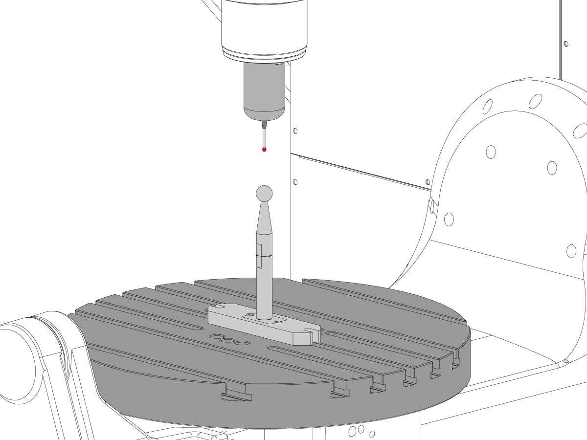
In this example, set parameter CHC Parameter 1314 to 7 or NGC Setting 254 to 0.0007.

Cycle the power to save CHC Parameter 1314 or NGC Setting 254.

Repeat Steps 1-3 to verify that the value for ∆Z is less than 0.0002" (0.005 mm).

4

Jog the B-Axis to the home position.

Set Parameter 151:20 (B-Axis CK Travel Limit) to 1.

Make sure the MRZP offsets are correct.

Calibrate WIPS per Wireless Intuitive Probe System (WIPS) - Calibration.

Complete an inspection report. Refer to UMC-750 Inspection Report.

Recently Viewed Items

You Have No Recently Viewed Items Yet

الملاحظات
Haas Logo

سعر تسليم Haas

يشمل هذا السعر تكلفة الشحن، ورسوم التصدير والاستيراد، والتأمين، وأي نفقات أخرى تحدث خلال الشحن إلى موقع في فرنسا بالاتفاق معك بوصفك المشتري. لا يمكن إضافة أي رسوم إلزامية أخرى إلى تسليم منتج بنظام التحكم الرقمي من Haas.

ابق على اطلاع بأحدث النصائح والتقنيات من HAAS…

سجِّل الآن!   

تقبل HAAS TOOLING ما يلي:

  • الخدمة والدعم
  • المالكون
  • طلب الخدمة
  • أدلة المُشغِّل
  • قطع غيار من Haas
  • طلب إصلاح الجزء الدوَّار
  • أدلة ما قبل التركيب
  • تسوق الأدوات
  • تركيب وسعر ماكينة Haas جديدة
  • المخزون المتاح
  • قائمة أسعار Haas
  • تمويل CNCA
  • لمحة عن Haas
  • بيان إمكانية الوصول
  • بيان DNSH
  • الامتثال لقواعد التصدير
  • الوظائف
  • الشهادات والسلامة
  • اتصل بنا
  • التاريخ
  • الشروط والأحكام
  • شروط وأحكام Haas Tooling
  • الخصوصية
  • الضمان
  • مجتمع Haas
  • برنامج شهادة كفائة من Haas
  • رياضة سباق السيارات في Haas
  • مؤسسة Gene Haas
  • مجتمع Haas الفني التعليمي
  • الفعاليات
  • الانضمام إلى المحادثة
  • Facebook
  • x
  • Flickr
  • YouTube
  • LinkedIn
  • Instagram
  • TikTok
© 2026 شركة Haas Automation – ماكينة بنظام التحكم الرقمي CNC

This site is protected by reCAPTCHA and the Google Privacy Policy and Terms of Service apply.

2800 Sturgis Rd., Oxnard, CA 93030 / Toll Free: 800-331-6746
Phone: 805-278-1800 / Fax: 805-278-2255