MyHaas Welcome,
!
Haas Tooling Guest Order History MyHaas/HaasConnect Sign In Register Haas Tooling My Account Order History Return History MyHaas/HaasConnect Sign Out Welcome, My Machines Latest Activity My Quotes My Account My Users Sign Out
Find Your Distributor
  1. Select Language
    1. English
    2. Deutsch
    3. Español - España
    4. Español - México
    5. Français
    6. Italiano
    7. Português
    8. Český
    9. Dansk
    10. Nederlands
    11. Magyar
    12. Polski
    13. Svenska
    14. Türkçe
    15. 中文
    16. Suomi
    17. Norsk
    18. الإنجليزية
    19. български
    20. Hrvatski
    21. Ελληνικά
    22. Română
    23. Slovenský
    24. Slovenščina
    25. 한국어
    26. 日本語
    27. Українська
  • machines Main Menu
    • Haas Vertical Mills Vertical Mills
      Vertical Mills
      Vertical Mills View All
      • Vertical Mills
      • VF Series
      • Universal Machines
      • VR Series
      • VP-5 Prismatic
      • Pallet-Changing VMCs
      • Mini Mills
      • Mold Machines
      • High-Speed Drill Centers
      • Drill/Tap/ Mill Series
      • Toolroom Mills
      • Compact Mills
      • Gantry Series
      • SR Sheet Routers
      • Extra-Large VMC
      • Double-Column Mills
      • Control Simulator
      • Mill Automatic Parts Loader
      • VMC/UMC Side-Loading Automatic Parts Loader
      • Compact Automatic Parts Loader
    • Product Image Multi-Axis Solutions
      Multi-Axis Solutions
      Multi-Axis Solutions View All
      • Multi-Axis Solutions
      • Y-Axis Lathes
      • 5-Axis Mills
    • Haas Lathes Lathes
      Lathes
      Lathes View All
      • Lathes
      • ST Series
      • Dual-Spindle
      • Box Way Series
      • Toolroom Lathes
      • Chucker Lathe
      • Haas Bar Feeder V2
      • Lathe Automatic Parts Loader
    • Haas Horizontal Mills Horizontal Mills
      Horizontal Mills
      Horizontal Mills View All
      • Horizontal Mills
      • 50-Taper
      • 40-Taper
    • Haas Rotaries & Indexers Rotaries & Indexers
      Rotaries & Indexers
      Rotaries & Indexers View All
      • Rotaries & Indexers
      • Rotary Tables
      • Indexers
      • 5-Axis Rotaries
      • Extra-Large Rotaries
    • Special Series
      Special Series
      Special Series View All
      • Special Series
      • EU_Series_Redirect
    • Product Image Automation Systems
      Automation Systems
      Automation Systems View All
      • Automation Systems
      • Mill Automation
      • Lathe Automation
      • Automation Models
    • Haas Drill Centers Desktop Machines
      Desktop Machines
      Desktop Machines View All
      • Desktop Machines
      • Desktop Mill
      • Desktop Lathe
    • Haas Shop Equipment Shop Equipment
      Shop Equipment
      Shop Equipment View All
      • Shop Equipment
      • Bandsaw
      • Knee Mill
      • Surface Grinder, 2550
      • Surface Grinder, 3063
      • Laser Cutting Machine
    • QUICK LINKS Special Series  Special Series 
      EU SERIES EU SERIES BUILD & PRICE | PRICE LIST BUILD & PRICE | PRICE LIST In-Stock Machines In-Stock Machines WHAT’S NEW WHAT’S NEW YOUR FIRST CNC YOUR FIRST CNC
      SHOPPING TOOLS
      • Build & Price a Haas
      • Price List
      • Available Inventory
      • CNCA Financing
      WANT TO TALK TO SOMEONE?

      A Haas Factory Outlet (HFO) can answer your questions, and walk you through your best options.

      CONTACT YOUR DISTRIBUTOR >
  • Options Main Menu
    • Product Image Spindles
      Spindles
      Spindles View All
      • Spindles
    • Product Image Tool Changers
      Tool Changers
      Tool Changers View All
      • Tool Changers
    • Product Image 4th- | 5th-Axis
      4th- | 5th-Axis
      4th- | 5th-Axis View All
      • 4th- | 5th-Axis
    • Product Image Turrets & Live Tooling
      Turrets & Live Tooling
      Turrets & Live Tooling View All
      • Turrets & Live Tooling
    • Product Image Probing
      Probing
      Probing View All
      • Probing
    • Haas Chip & Coolant Management Chip & Coolant Management
      Chip & Coolant Management
      Chip & Coolant Management View All
      • Chip & Coolant Management
    • The Haas Control The Haas Control
      The Haas Control
      The Haas Control View All
      • The Haas Control
    • Product Image Product Options
      Product Options
      Product Options View All
      • Product Options
    • Product Image Tooling & Fixturing
      Tooling & Fixturing
      Tooling & Fixturing View All
      • Tooling & Fixturing
    • Product Image Workholding
      Workholding
      Workholding View All
      • Workholding
    • Product Image 5-Axis Solutions
      5-Axis Solutions
      5-Axis Solutions View All
      • 5-Axis Solutions
      • 5 Easy Steps to 5-Axis
    • QUICK LINKS Special Series  Special Series 
      EU SERIES EU SERIES BUILD & PRICE | PRICE LIST BUILD & PRICE | PRICE LIST In-Stock Machines In-Stock Machines WHAT’S NEW WHAT’S NEW YOUR FIRST CNC YOUR FIRST CNC
      SHOPPING TOOLS
      • Build & Price a Haas
      • Price List
      • Available Inventory
      • CNCA Financing
      WANT TO TALK TO SOMEONE?

      A Haas Factory Outlet (HFO) can answer your questions, and walk you through your best options.

      CONTACT YOUR DISTRIBUTOR >
  • Why Haas Main Menu
      Discover the Haas Difference
    • Why Haas
    • MyHaas
    • Education Community
    • Industry 4.0
    • Haas Certification
    • Customer Testimonials
  • Service Main Menu
      Welcome to Haas Service
      SERVICE HOME Operator’s Manuals How-To Procedures Troubleshooting Guides Preventive Maintenance Haas Parts Haas Tooling Videos
  • Videos Main Menu
  • Main Menu
    • View All
    • View All
      • Fiber Laser
    • View All
    • View All
      • HTEC Curriculum Support
    • View All
      • Haas 10 kg Cobot Package
      • Cobot Kits
    • View All
    • View All
      • 4 - AUTOMATION SYSTEMS
      • Mill Toolholding
      • Carousel-V2
    • View All
    • View All
    • View All
      • VF-4SS
    • View All
    • QUICK LINKS Special Series  Special Series 
      EU SERIES EU SERIES BUILD & PRICE | PRICE LIST BUILD & PRICE | PRICE LIST In-Stock Machines In-Stock Machines WHAT’S NEW WHAT’S NEW YOUR FIRST CNC YOUR FIRST CNC
      SHOPPING TOOLS
      • Build & Price a Haas
      • Price List
      • Available Inventory
      • CNCA Financing
      WANT TO TALK TO SOMEONE?

      A Haas Factory Outlet (HFO) can answer your questions, and walk you through your best options.

      CONTACT YOUR DISTRIBUTOR >
  • Haas Tooling Main Menu
      Automation Accessories Shop Support Mill Toolholding Mill Cutting Tools Boring Systems Mill Workholding Lathe Toolholding Lathe Cutting Tools Lathe Workholding Package Kits ER Collets & Chucks Holemaking Threading Broaching Tombstones & Kits Manual Chucks For Milling Deburring & Abrasives Tool Presetter & Heat Shrinkers Storage & Handling Machine Maintenance Tooling Accessories Apparel & Accessories Measuring & Inspection Winner's Circle Winner's Circle Clearance Today's Hot Deals
    • Haas Tooling
    • Winner's Circle
      Winner's Circle Shop All
      • WINNERS_CIRCLE-1Y
    • Winner's Circle
      Winner's Circle Shop All
      • WC-1Y-EU
    • Today’s Hot Deals
      Today’s Hot Deals Shop All
      • Mill Toolholding
      • Mill Tooling
      • Measuring & Inspection
      • Boring Systems
      • Mill Workholding
      • Shell Mill Kits
      • Lathe Toolholding
      • Lathe Tooling
      • Lathe Workholding
      • ER Collets & Chucks
      • Holemaking
      • Threading
      • Broaching
      • Tool Storage
      • Apparel & Accessories
    • Clearance
      Clearance Shop All
    • Measuring & Inspection
      Measuring & Inspection Shop All
      • Probe Kits & Accessories
      • Edge & Center Finders
      • Comparative Measuring Gauges
      • Height Gauges
      • Calipers
      • Threaded Plug & Ring Gauges
      • Gauge Blocks
      • Pin Gauges
      • Drop Indicators
      • Dial Test Indicators
      • Bore Gauges
      • Indicator Accessories
      • V Blocks
      • Setup Blocks
      • Depth Measuring
      • Micrometers
      • Micrometer Accessories
      • Micrometer Kits
      • Bore Gauge Kits
      • Starter Kits
      • Indicator Kits
      • Caliper Kits
      • Toolholder Check Station
      • Height Setters
      • Coordinate Measuring Machines
    • Automation Accessories
      Automation Accessories Shop All
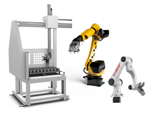
      • Cobot Kits
      • Cobot Kits
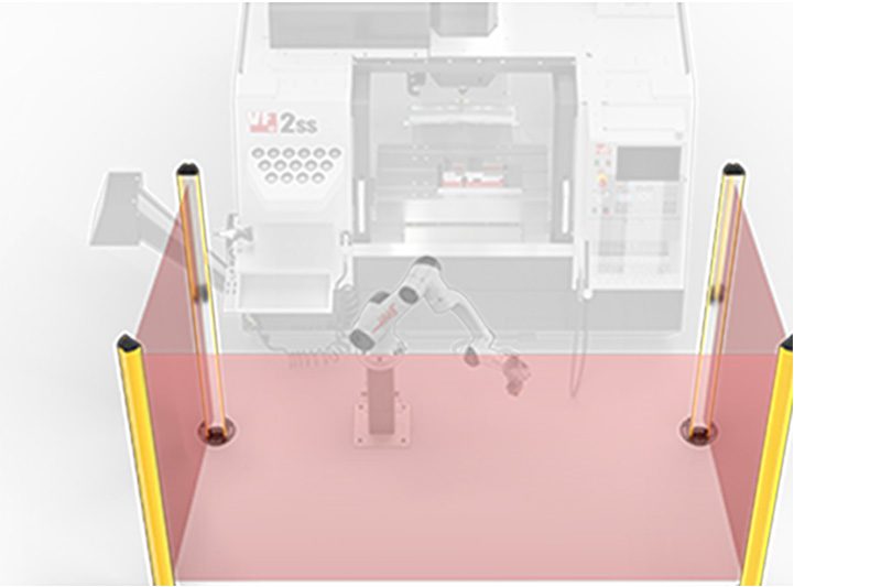
      • Protective Barriers
      • Grippers
      • Robot Cell Accessories
    • Shop Support
      Shop Support Shop All
      • Air Compressors
      • Laser Marking Machines
      • Bandsaw Blades
      • Bandsaw Accessories
      • Surface Grinding Wheels
      • Shop Equipment Accessories
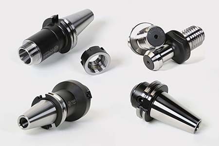
    • Mill Toolholding
      Mill Toolholding Shop All
      • End Mill Holders
      • Shell Mill Holders
      • Shrink Fit Holders
      • ER Collet Chucks
      • Milling Chucks & Collets
      • NC Drilling Chucks
      • Pull Studs / Retention Knobs
      • Rotary Tool Holder & Tool Chuck Kits
      • Hydraulic Milling Chucks & Collets
      • Toolholder Attachments & Wrenches
      • Mill Broaching Holders
    • Mill Tooling
      Mill Tooling Shop All
      • Shell Mill Bodies
      • Milling Inserts
      • End Mills
      • Chamfer Mills & Inserts
      • Indexable End Mill Bodies
      • Ball End Mills
      • Chamfer End Mills
      • Roughing End Mills
      • Indexable Ball End Mills & Inserts
      • Shell Mill Kits
      • Chamfer Mill Kits
      • Indexable End Mill Kits
      • Dovetail Cutters
      • Indexable Dovetail Cutters
      • Engraving End Mills
      • Rotary Burrs / Die Grinding Bits
      • Keyseat Cutters
      • Corner Rounding End Mills
      • Slot Mill Bodies
      • CNC Router Bits For Wood
    • Boring Systems
      Boring Systems Shop All
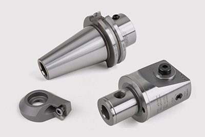
      • Boring Heads & Cartridges
      • Boring Holders & Extensions
    • Mill Workholding
      Mill Workholding Shop All
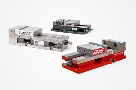
      • Fixed-Jaw Vises
      • Self-Centering Vises
      • Adapter Plates
      • Vise Jaws
      • Vise Mounts & Fixtures
      • Vise Kits
      • Vise Parallels
      • Rotary Vise Kits
      • Fixture Clamps & Rails
      • Automated Workholding Kits
      • Tooling Fixture Subplates
      • Toolmakers' Vises
      • Clamp Force Gauges
      • Collet Fixtures
      • Angle Plates
    • Lathe Toolholding
      Lathe Toolholding Shop All
      • TL & CL Static Turning Holders
      • BOT Static Turning Holders
      • BMT Static Turning Holders
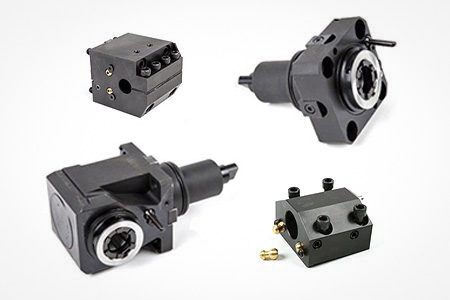
      • Live / Driven Turning Holders
      • Turning Holder Reduction Sleeves / Bushings
      • VDI Static Turning Holders
      • Turning Holder Accessories
    • Lathe Tooling
      Lathe Tooling Shop All
      • Cut-Off Tool Blocks & Blades
      • Cut-Off Tooling Kits
      • Turning Inserts
      • Grooving & Cut-Off Tools
      • Internal (ID) Grooving & Threading Tools
      • Threading Inserts
      • Threading Tools
      • Boring Bars / Internal (ID) Turning Tools
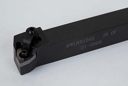
      • External (OD) Turning Tools
      • Cermet Turning Inserts
      • CBN Turning Inserts
      • Haas Notch Grooving & Threading Inserts
      • Haas Notch Grooving & Threading Tools
      • Micro Turning Tools
      • Desktop Lathe Tools
    • Lathe Workholding
      Lathe Workholding Shop All
      • Live Centers
      • Spindle Reduction Sleeves / Liners
      • Quick-Change Collets
      • Quick-Change Collet Chucks
      • 5C Collets
      • 5C Collet Sets
      • Lathe Jaw Boring Rings
      • Lathe Jaws
      • Bar Pullers
      • Scroll Chucks
      • Guide Pins
      • Collet Accessories
    • Package Kits
      Package Kits Shop All
      • Chip Clearing Fan Kits
      • Cutting Tool Kits
      • Indexable End Mill Kits
      • Cut-Off Tool Block & Blade Kits
      • Drill & Tap Kits
      • Indexable Drilling Kits
      • Shell Mill Kits
      • Chamfer Mill Kits
      • Rotary Tool Holder & Tool Chuck Kits
      • Lathe Starter Kits
      • Workholding Kits
      • Rotary Vise Kits
      • Vise Kits
      • 3-Jaw Chuck Kits for Mills
      • Tombstone Kits
      • Reduction Sleeve Kits
      • Automated Workholding Kits
      • Measuring & Inspection Kits
      • Starter Kits
      • Bore Gauge Kits
      • Caliper Kits
      • Indicator Kits
      • Micrometer Kits
    • ER Collets & Chucks
      ER Collets & Chucks Shop All
      • ER Straight-Bore Collets
      • ER Sealed Collets
      • ER Tap Collets
      • ER Collet Sets & Accessories
      • ER Collet Chucks
      • Straight Shank ER Collet Chucks
      • Straight Shank Keyless NC Drilling Chucks
    • Holemaking
      Holemaking Shop All
      • Carbide Drills
      • Indexable Drill Bodies
      • Indexable Drill Inserts
      • Modular Drill Bodies
      • Modular Drill Heads
      • Cobalt Drills & Sets
      • Center Drills
      • Reamers
      • Indexable Drilling Kits
      • Spot Drills
      • Spade Drill Bodies
      • Spade Drill Inserts
      • Countersinks
    • Threading
      Threading Shop All
      • Taps
      • Threading Inserts
      • Threading Tools
      • Thread Mills
      • Pipe Taps
      • Drill Tap Kits
    • Broaching
      Broaching Shop All
      • Broaching Tools
      • Broaching Inserts
    • Tombstones
      Tombstones Shop All
      • Tombstones
      • Tombstone Kits
      • Vise Cluster Towers
    • Manual Chucks For Milling
      Manual Chucks For Milling Shop All
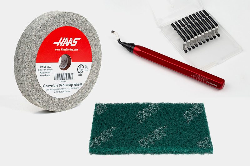
      • 3-Jaw Chucks & Mounts for Mills
    • Deburring & Abrasives
      Deburring & Abrasives Shop All
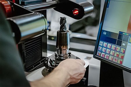
      • Abrasive Pads
      • Deburr Tools
      • Deburr Wheels
      • Abrasive Sheets & Rolls
      • Sharpening / Lapping Stones
    • Tool Presetter & Heat Shrinkers
      Tool Presetter & Heat Shrinkers Shop All
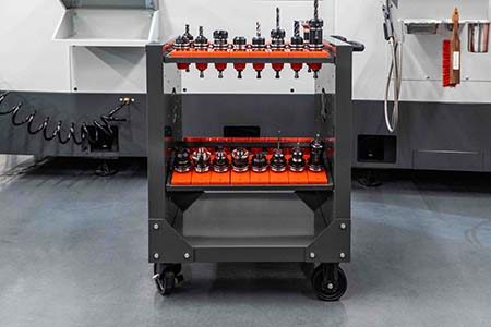
      • Tool Presetting Machines
      • Shrink Fit Machines
    • Tool Storage
      Tool Storage Shop All
      • Tool Carts
      • Tool Tray
      • Tool Bags
    • Machine Maintenance
      Machine Maintenance Shop All
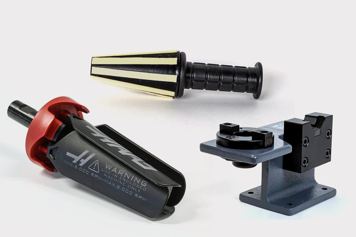
      • Spindle Test Bars
      • Levels
      • Refractometers
      • Machine Additives & Supplies
      • Machine Accessories
      • Machine Maintenance Kits
    • Tooling Accessories
      Tooling Accessories Shop All

      • Spindle & Toolholder Taper Cleaners
      • Haas Shop Lift
      • Toolholder Fixtures
      • CNC Chip Clearing Fans
      • Hammers & Mallets
      • Anti-Fatigue Mats
      • Layout Tools
      • Wrenches
      • Magnetic Tools
      • Torque Screwdrivers
      • Hand Cutting Tools
      • Shop Stools
      • Lifting Magnets
      • Safety Apparel
      • Cutting Tool Sharpeners
    • Apparel & Accessories
      Apparel & Accessories Shop All
      • Accessories
      • Apparel
    • HAAS TOOLING QUICK LINKS
      NEW PRODUCTS NEW PRODUCTS NEW PRODUCTS NEW PRODUCTS
      MOST POPULAR MOST POPULAR
      TOOLING PROMOS TOOLING PROMOS
      FINANCING & OPEN TERMS FINANCING & OPEN TERMS PAY BY INVOICE PAY BY INVOICE
      FAQs FAQs
      KITS CREATED FOR YOU KITS CREATED FOR YOU
  • Haas Service Parts Main Menu
      Automatic Pallet Changer Lathe Turret Tool Changer Chip Management Coolant Counterbalance Electrical Cabinet Enclosure Hydraulics Lubrication Maintenance Pendant Probing Rotary Spindle Tailstock
    • Haas Service Parts
    • Automatic Pallet Changer
      Automatic Pallet Changer Shop All
      • HMC - Automatic Pallet Changer
      • VMC - Automatic Pallet Changer
    • Lathe Turret
      Lathe Turret Shop All
      • Lathe - Turret
      • Live Tooling
    • Tool Changer
      Tool Changer Shop All
      • Side Mount
      • Umbrella
    • Chip Management
      Chip Management Shop All
      • Multi Auger
      • Single Auger
    • Coolant
      Coolant Shop All
      • Auxiliary Filter
      • HPC-300 (Lathe)
      • HPC-1000 (Lathe)
      • Oil Skimmer
      • Standard Coolant
      • TSC-300 (Mill)
      • TSC-1000 (Mill)
      • Coolant Refill
      • Loc-Line
    • Counterbalance
      Counterbalance Shop All
      • Charge & Discharge Hose
    • Electrical Cabinet
      Electrical Cabinet Shop All
      • Fans
      • Filters
      • Upgrade Kits
    • Enclosure
      Enclosure Shop All
      • Accessories
      • Air Nozzle
      • Decals
      • Door Bumpers
      • Lighting
      • Windows, Gaskets, & Weather Strip
      • Chip & Coolant Management
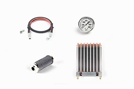
    • Hydraulics
      Hydraulics Shop All
      • Filters
      • Gauges
      • Heat Exchanger
      • Hoses
    • Lubrication
      Lubrication Shop All
      • Bijur Mechanical Lubrication
      • Minimum Lubrication
    • Maintenance
      Maintenance Shop All
      • Grease, Oil, & Sealants
    • Pendant
      Pendant Shop All
      • Floppy Disk & USB
      • Keypad
      • Keys
      • Lens
      • Gaskets & Seals
    • Probing
      Probing Shop All
      • Mill Probing
      • Lathe Tool Presetter
    • Rotary
      Rotary Shop All
      • Rotary Gaskets & Seals
    • Spindles
      Spindles Shop All
      • Couplings
      • Gaskets & Seals
      • Spindle Motor Drive
      • Gearbox Drive
      • Tool Release Piston
    • Tailstock
      Tailstock Shop All
      • Handles
×

Search Results

Web Pages

Images

    • <
    • 1
    • >
MyHaas Welcome,
!
Haas Tooling Guest Order History MyHaas/HaasConnect Sign In Register Haas Tooling My Account Order History Return History MyHaas/HaasConnect Sign Out Welcome, My Machines Latest Activity My Quotes My Account My Users Sign Out
Find Your Distributor
  1. Select Language
    1. English
    2. Deutsch
    3. Español - España
    4. Español - México
    5. Français
    6. Italiano
    7. Português
    8. Český
    9. Dansk
    10. Nederlands
    11. Magyar
    12. Polski
    13. Svenska
    14. Türkçe
    15. 中文
    16. Suomi
    17. Norsk
    18. الإنجليزية
    19. български
    20. Hrvatski
    21. Ελληνικά
    22. Română
    23. Slovenský
    24. Slovenščina
    25. 한국어
    26. 日本語
    27. Українська
×

Search Results

Web Pages

Images

    • <
    • 1
    • >

8 - UMC - Geometry and Alignment

UMC-Series - Service Manual


  • 1 - UMC - Introduction
  • 2 - UMC - Specifications
  • 3 - UMC-400/500/750 - Installation
  • 4 - UMC-1000/1250 - Installation
  • 5 - UMC-1500-DUO/1600-H - Installation
  • 6 - UMC - Anchoring
  • 7 - UMC - Operation
  • 8 - UMC - Geometry and Alignment
  • 9 - UMC - MRZP and Safe Zones
  • 10 - UMC - B/C - Rotary Axis
  • 11 - UMC - Tool Changer
  • 12 - UMC - Chip Removal and Coolant
  • 13 - UMC - Electrical Control
  • 14 - UMC - Lubrication
  • 15 - UMC - Maintenance
  • 16 - UMC - Pallet Pool
  • 17 - UMC - Hydraulic Workholding
  • 18 - UMC - Pneumatic Workholding

Go To :

  • 8.1 Geometry Guide
  • 8.2 Alignment - Indicating Zones
  • 8.3 Geometry - Troubleshooting
  • 8.4 Applications - Troubleshooting
  • 8.5 UMC-750 - Shim Kit Checklist
  • 8.6 B/C - Axis Intersection - Alignment

8.1 Geometry Guide

Recently Updated

Geometry Guide - UMC-Series


Introduction

  1. Spindle Head
  2. Ram
  3. Saddle
  4. Bridge
  5. Base
  6. C-Axis Rotary
  7. B-Axis Rotary

Before beginning record the factory-set the value for the parameter or setting below. You will need to set this to zero while making adjustments, and then reset it to the original value when finished. The value could be positive or negative.

  • Classic Haas Control (CHC) Parameter 1314 (Rotary Axes Center Deviation in X)
  • Next Generation Control (NGC) Setting 254 (5 Axis Rotary Center Distance)

Tooling and Kits Required:

  • T-2193A - UMC-750 SPINDLE HEAD ALIGNMENT PIN *
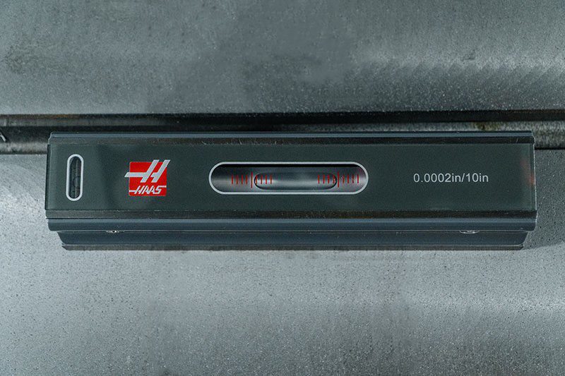
  • T-2181 - CNC DUAL LEVELING TOOL
  • T-2192 - LEVELING ADAPTER UMC-750
  • 93-2236 - SHIM KIT FOR UMC-750 *

Click on the link to see the  UMC-750 Leveling and Alignment video.

*  : Used only on Pre-Reboot series. 

Level the Machine

1

Set the machine height:

Move the X and Y axes to the home position.

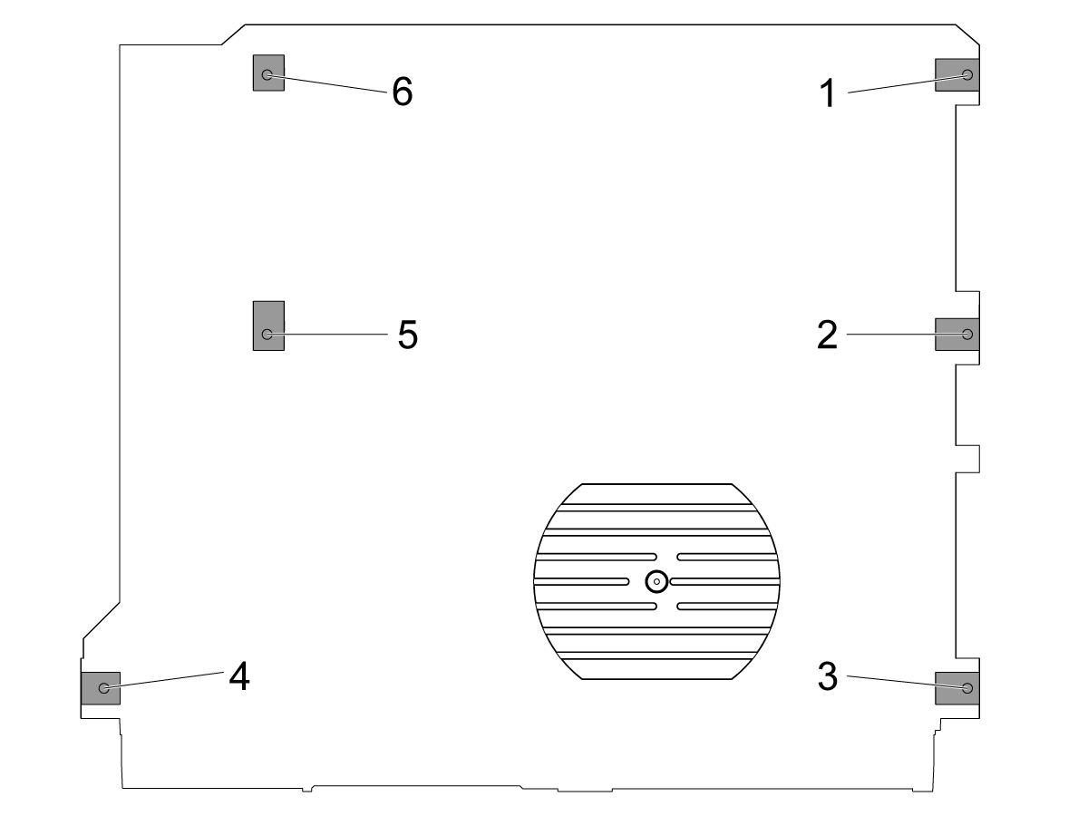
Loosen the middle leveling screws [2 and 5] so that they are not supporting any weight.

Set the machine on 4 corner leveling screws 3" (76.2 mm) above the floor.

2

Rough level the machine:

Turn the leveling screw #4 up.

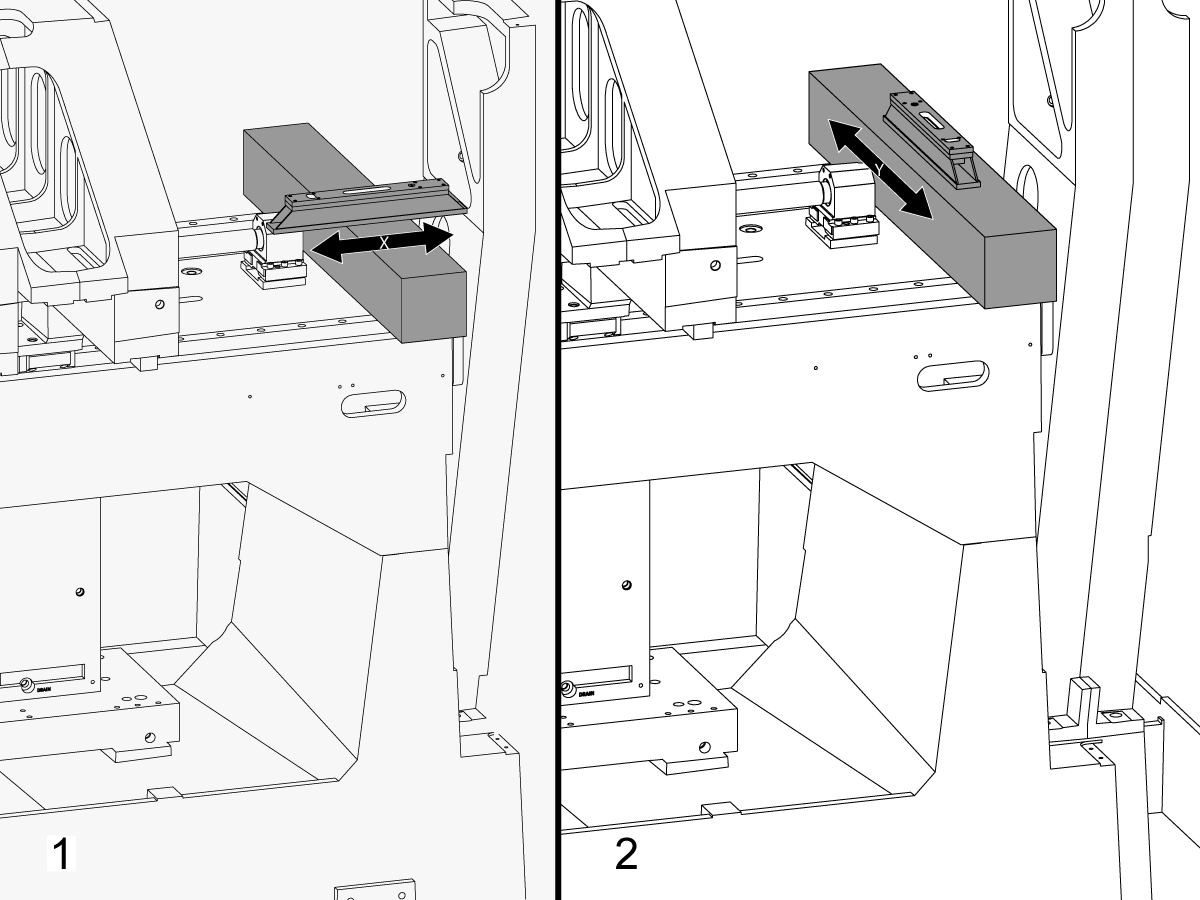
Place the granite across the X axis linear guides near the X axis ballscrew bearing support.

Setup the machinist level on top of the granite parallel to the X axis.[1]

Adjust the leveling screw #6 until the machine is leveled in X axis.

Setup the machinist level on top of the granite perpendicular to the X axis.[2]

Adjust the leveling screw #3 until machine is leveled in Y axis.

Turn the leveling screw #4 down until it makes the contact with the leveling pad.

3

Adjust X Axis roll:

Assemble T-2192 with T-2181.

Move the Y Axis to the middle of the travel.

Put T-2192 on the side of the spindle.

Make sure the bubble on T-2181 is within readable range.

If it's not, loosen the bolt that secures T-2192 to the magnetic base and move the adapter as needed.

Jog the X Axis side to side and measure the X Axis roll. Take readings at the home position, middle, and the end of the travel.

Adjust the leveling screw #4 intil there is no deviation between the reading at home position and the reading at the end of the travel.

Note: The bubble on T-2181 does NOT have to be in the middle of the vial. It only needs to be within readable range.

4

Set the middle leveling screws:

Turn middle leveling screws down until they make the contact with the leveling pads and then turn them an additional 45°.

Verify the X Axis roll. Adjust the middle leveling screws to correct the X Axis roll.

X Axis to Y Axis Alignment

1

Align the face of the saddle parallel to the X Axis movement:

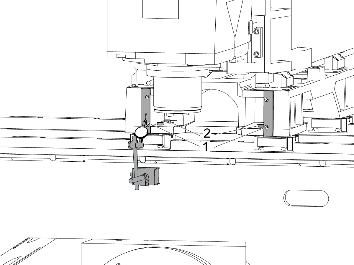
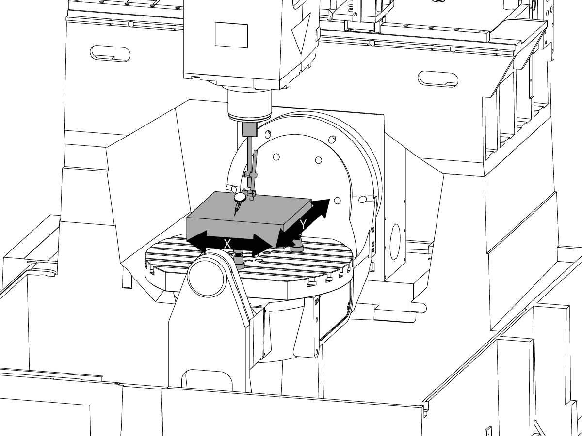
Sweep across the machined surface on the front of the saddle [1] by jogging the X Axis.

Loosen the bolts that secure saddle to the X Axis trucks [2] and align the the face of the saddle parallel to the X Axis movement within 0.001" if needed.

Torque the bolts. Refer to Haas Fastener Torque Specifications.

2

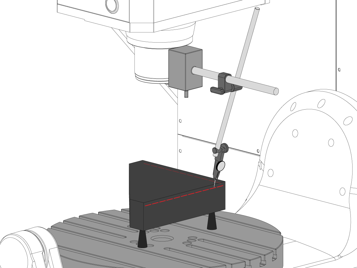
Align the Y axis perpendicular to the X Axis:

Setup the tri-square granite on the left side of the C Axis platter on the machinist jacks.

Set the back side of the tri-square granite parallel to the X Axis. NTE 0.0001"/10"

Sweep the top of the tri-square granite along the X and Y axes.

Adjust the machinist jacks until top surface of the tri-square granite is parallel to the X-Y plane NTE 0.0005".

Verify that the back side of the granite parallel to the X Axis. NTE 0.0001"/10".

Loosen the bolts that secure the Y Axis trucks to the saddle and align the Y Axis perpendicular to the X Axis. NTE 0.0005"/10"

Torque the bolts. Refer to Haas Fastener Torque Specifications.

Verify the Y Axis perpendicular to the X Axis NTE 0.0005"/10" after bolts are torqued.

Z Axis to the X-Y Plane Alignment

1

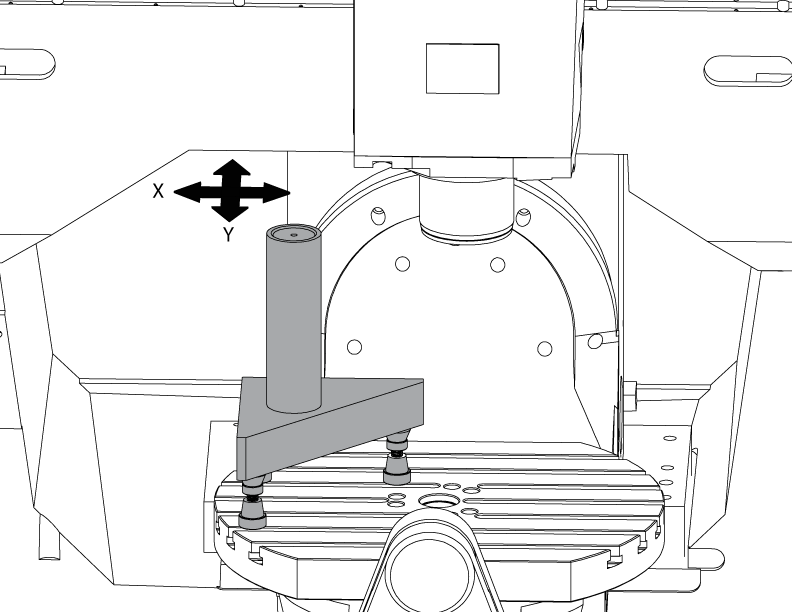
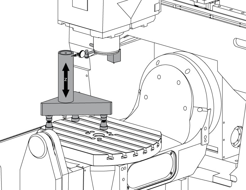
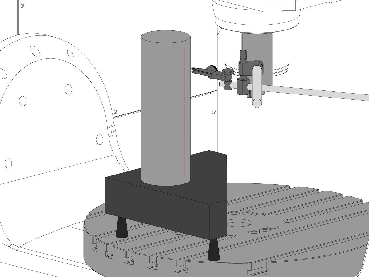
Set-up the cylinder.

Put a cylinder on top of the tri-stone as shown in the picture.

Align the top surface of the cylinder parallel to X-Y plane NTE 0.0001" by turning the machinist jacks.

Jog the machine to the following position:

  • UMC-750 to X -7.000" and Y -10.000"
  • UMC-750SS to X -10.000" and Y-10.000"

2

Align the Z Axis perpendicular to the X Axis:

Replace one of the top corner bolts on the Z Axis trucks with the T-2193A * to pivot the spindle head around it.

Indicate the side of the cylinder along the Z Axis.

Loosen the bolts that secure Z Axis trucks to the ram.

Align the Z Axis perpendicular to X Axis NTE 0.0005"/10" by swinging the spindlehead side to side.

Torque the bolts. Refer to Haas Fastener Torque Specifications.

Verify that the Z Axis perpendicular to the X Axis after bolts are torqued.

Replace the T-2193A * with the bolt when alignment is done

*  : Used only on Pre-Reboot series. 

3

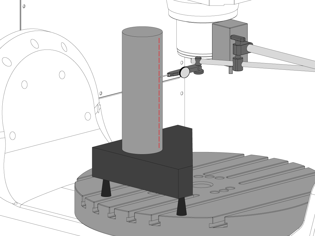
Align the Z Axis perpendicular to Y Axis:

Indicate the front of the cylinder along the Z Axis.

Shim between Z Axis trucks and the ram to align the Z Axis perpendicular to the Y Axis NTE 0.0005"/10".

Note: Shim either top two trucks or the bottom two trucks with the equal shims.

Torque the bolts. Refer to Haas Fastener Torque Specifications.

Verify that the Z Axis perpendicular to the Y and the X axes after bolts are torqued.

4

Align and torque Y and Z axes ballnut housings:

Loosen the bolts that secure the ballnut to the housing and bolts that secure the housing to the casting.

Snug the bolts that secure the ballnut housing to the casting first, then snug the bolts that secure ballnut to the housing.

Use the Jog Lock function to run the axis back and forth full travel.

Note: Do not use handwheel or the rapid move.

Torque the bolts. Refer to Haas Fastener Torque Specifications.

The Y-axis nut housing can be accessed in the rear of the machine with the ram jogged all the way toward the front of the machine.

The Z-axis nut housing can be accessed from the front of the machine with the spindle head jogged all the way down.

Note: Spindle motor shroud needs to be removed to access the Z axis ballnut housing.

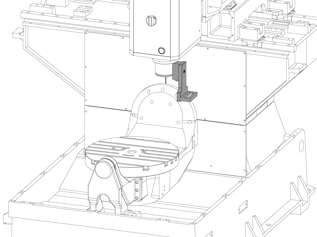
Tram the Spindle to the X-Y Plane

1

Set up the granite:

Setup the machinist jacks and the granite on the middle of the C Axis platter as shown in the picture.

Align the top surface of the granite parallel to X-Y plane by adjusting the machinist jacks height NTE 0.0001".

Position the spindle over the center of the platter.

2

Tram the spindle to the X-Y plane:

Put an indicator onto the spindle shaft.

Make a measurement on top of the granite at every 90° of rotation.

Loosen the (6) bolts in the base plate for the spindle head.

Add or remove shims between the spindle head casting and the base plate to tram the spindle to the X-Y plane NTE 0.0005"/10".

Note: Use shims of unequal thickness [1] to change the angle of the base plate.

When the sweep is within specification, torque the (6) bolts. Refer to Haas Fastener Torque Specifications.

Verify spindle tram after bolts are torqued.

B Axis to XYZ Axes Alignment

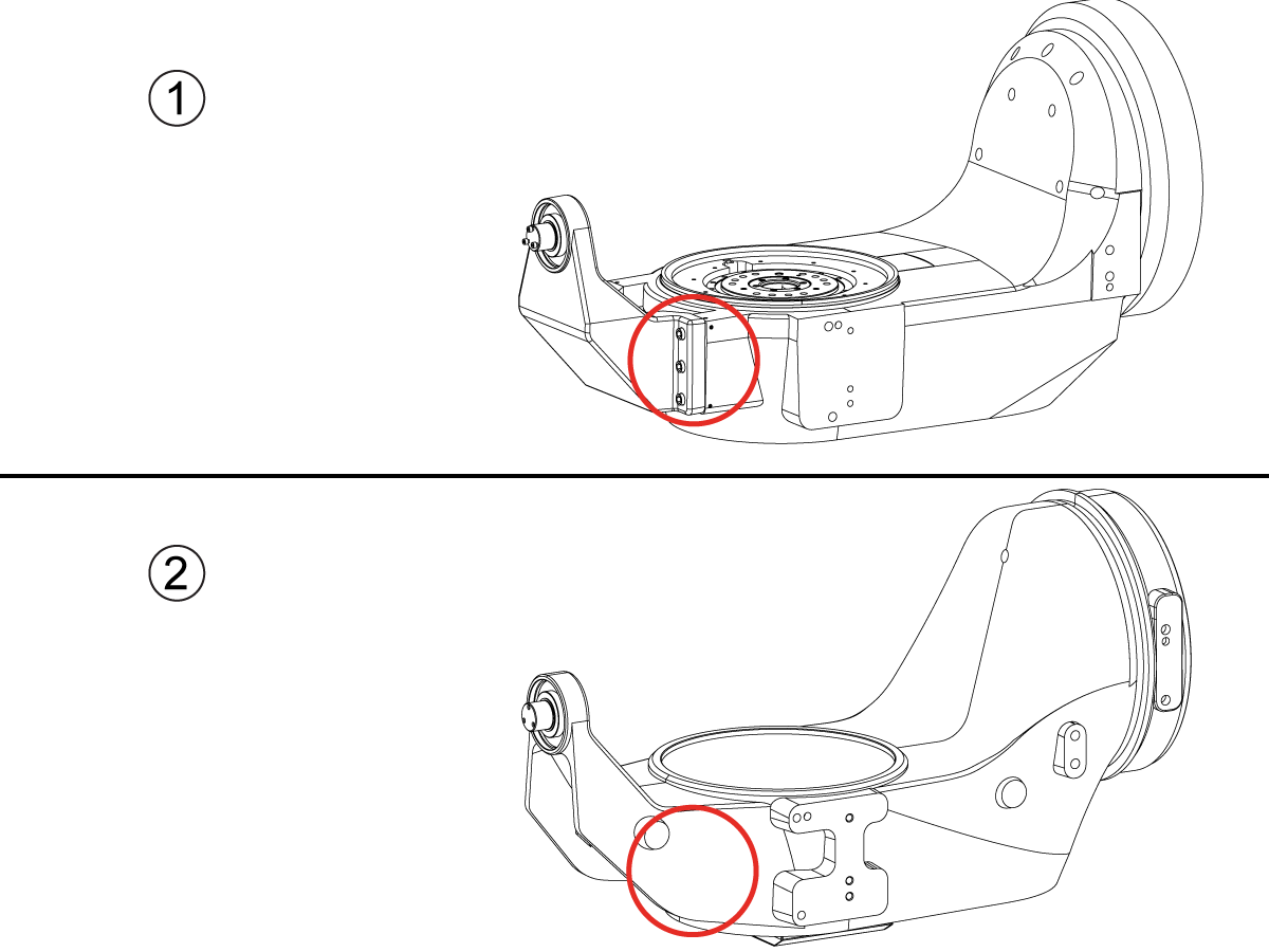
How to identify the Multi-Piece and the Unibody trunnion   

1) Multi-Piece trunnion:    UMC machines built approximetely before 11/2022 will have this configuration.

2) Unibody trunnion:    UMC machines built approximetely after 11/2022 will have this configuration.

1

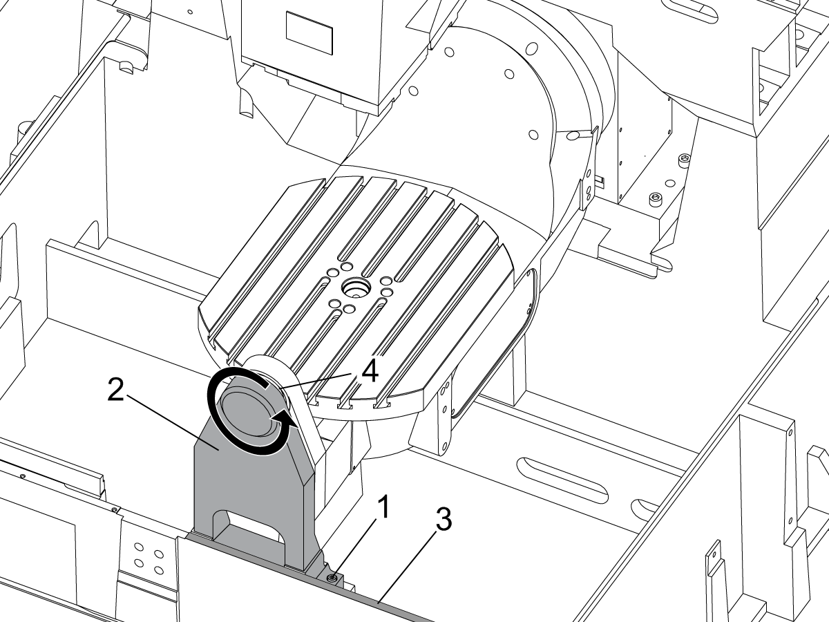
Remove the A-frame trunnion support:

Remove the bolts [1] that secure the A-frame trunnion support [2] to the base and take out the shims between A-frame support and the base.

Rotate the A-frame support [2] counter-clockwise to clear the edge of the base [3].

Pull the A-frame support off the bearings.

 Note: The A-frame support might vacuum lock on the bearings. Use the zip-tie to pry the seal [4] open.

 Caution: To lift the trunnion support, get the aid of another person. The support weighs 85 lbs (39 kg).

2

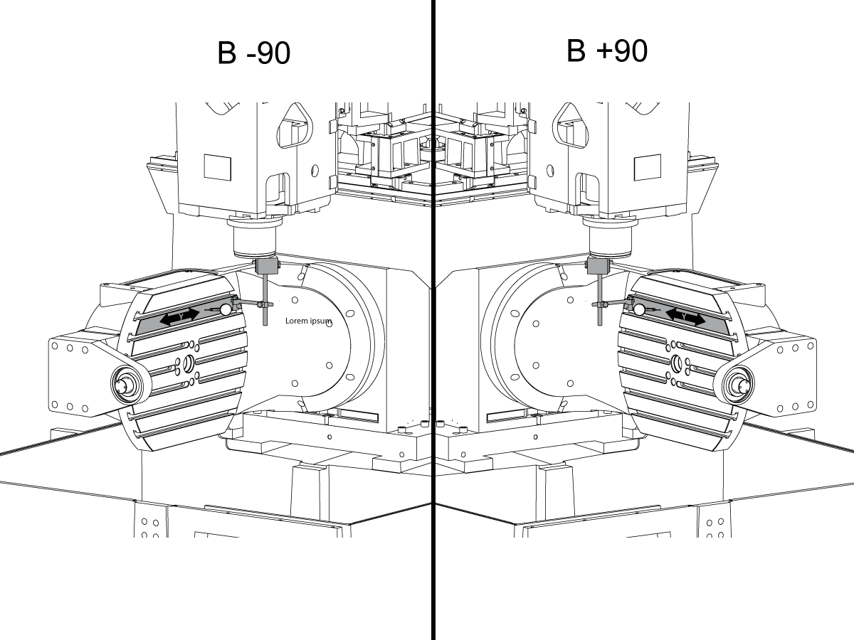
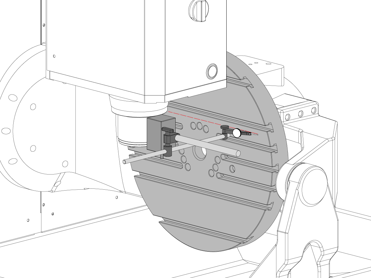
Measure the B- axis of rotation parallelism to the Y-Z plane:

For a machine with a Classic Haas Control, change Parameter 151:20 (B axis CHK TRAVL LIM) to 0.

For a machine with a Next Generation Control, change Parameter 6.021 (B axis CHK TRAVL LIM) to FALSE.

Measure the parallelism of the platter to the Y-Z plane with the B axis at 90° and then the B axis at -90° as shown in the picture.

Position the Y-Axis in the following starting position:

UMC-500: Y=0, Sweep 15”, 3rd T-Slot Land from the top.

UMC-750/1500-Duo: Y=-1.0, Sweep 18", 3rd T-Slot Land from the Top .

UMC-1250: Y=-1.0, Sweep 28", 3rd T-Slot Land from the Top.

UMC-500PP: Y=-4.0, Sweep 7".

UMC-750PP: Y=-2”, Sweep 15".

UMC-1000PP: Y=-4”, Sweep 15".

Compare the results at B 90° and B-90°. The results should be...

  • Symmetric against the Y-Z plane, positive or negative direction
  • Less than 0.0010"/20"

If the results are symmetric against Y-Z plane, and are less than 0.0010"/20 inches: Go to Step 5.

If the results are symmetric against Y-Z plane, but are more than 0.0010"/20 inches: Go to Step 4.

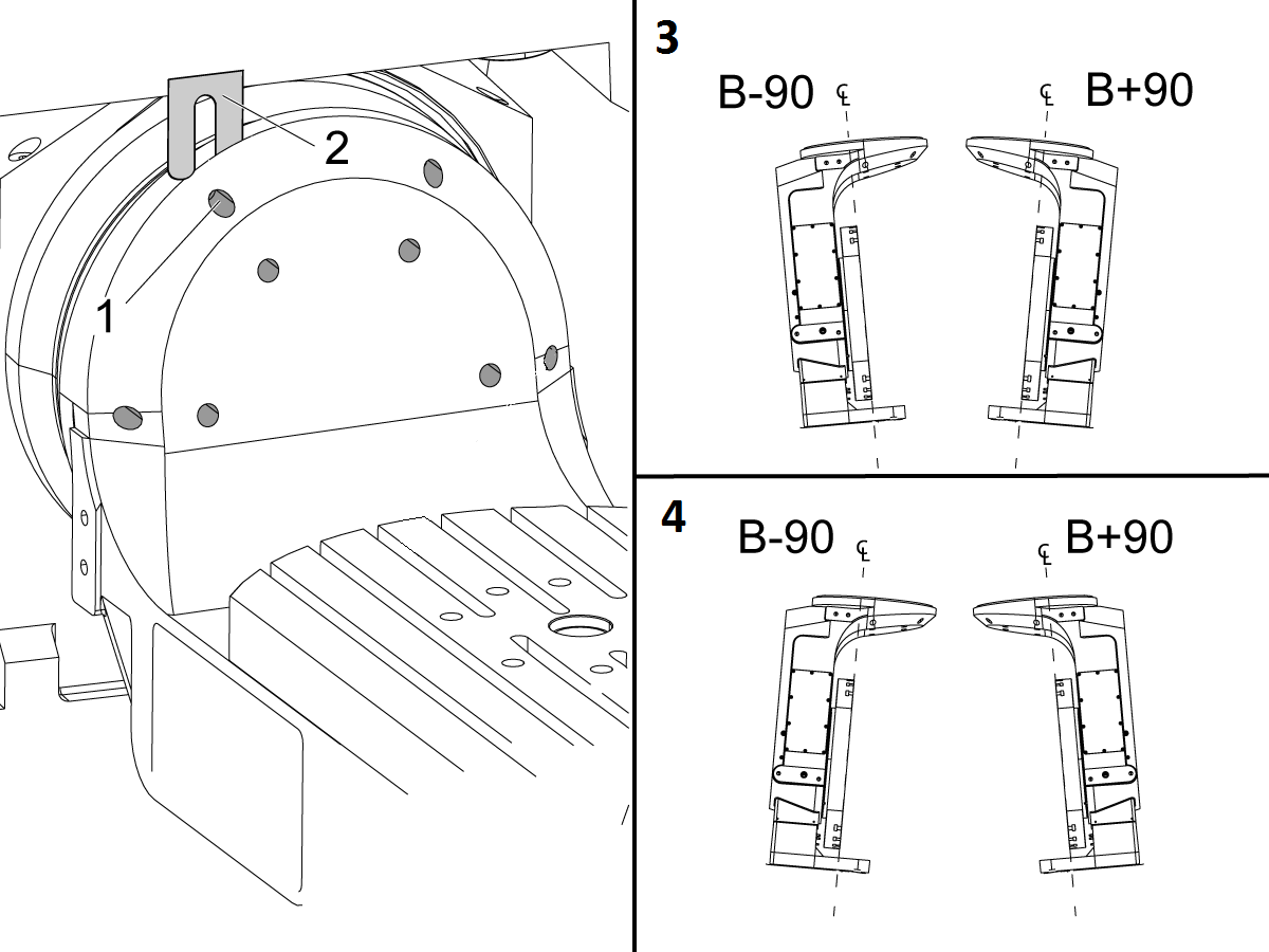
 Warning: If the results [3] are not symmetric against the Y-Z plane, the B axis rotary needs to be aligned: Go to Step 3.

3

Align the B axis of rotation parallel to the Y-Z plane:

Loosen the (6) bolts [1] that secure the B axis rotary to the base casting.

 Note: Keep the bolts sufficiently snug to control the adjustments.

Adjust the front and rear setscrews [2] until the measurements taken in Step 2 are symmetric against the Y-Z plane.

Torque the (6) bolts [1]. Refer to Haas Fastener Torque Specification.

Verify the measurements in Step 2 after the bolts have been torqued.

4

Align the C Axis of rotation perpendicular to the B Axis of rotation:

Remove the bottom C-Axis access cover.

Loosen the (12) bolts [1] that hold the C Axis body to the B Axis platter face.

Reach the bottom (4) bolts through the C Axis access port.

If the B Axis is symmetric in the positive direction [4], install horseshoe shims [2] of appropriate size behind the top (2) bolts.

If the B Axis is symmetric in the negative direction [5], install horseshoe shims [2] of appropriate size behind the bottom (2) bolts.

Torque the (12) bolts to 80 Ft-lbs (108 Nm).

Cut the excessive shim material off.

Verify the measurements in Step 2 after bolts are torqued.

5

Align the trunnion support shaft co-axial with the B Axis of rotation:

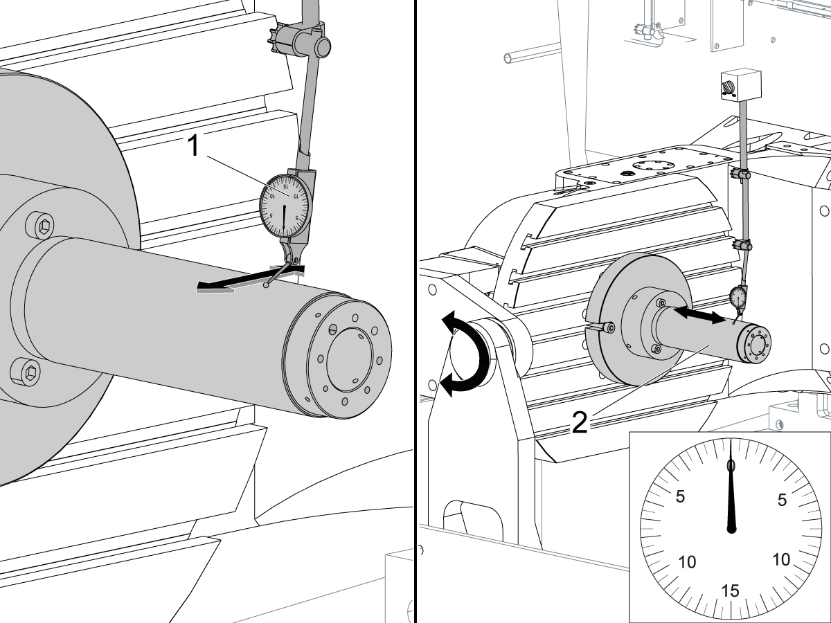
Setup (2) indicators on the outer race of the trunnion support bearing [2] as shown in the picture.

Mark the spot on the outer race where one of the indicator needles is contacting the surface.

After moving the B Axis to 90° or -90° you will align the marked spot with the needle again to exclude the bearing runout error from the measurements.

Take the readings when B is at 90° and B at -90°. Compare the readings. 

 Caution: The B axis brake needs to be clamped when taking the readings.

The deviation between the results when B is at 90° and at -90° needs to be less than 0.001" on each indicator.

 Note: The indicator on the side of the bearing will measure top to bottom alignment and the indicator on the top of the bearing will measure side to side alignment.

____

For models with a multi-piece trunnion

Loosen the (6) bolts [3] on the C Axis body support. Keep the bolts sufficiently snug to control adjustment.

Adjust the (8) set screws [4] until deviation between B at 90° and B at -90° is within 0.001".

Torque the (6) bolts [2] on the C Axis body support to 80 Ft-lbs (108 Nm).

Verify the alignment after the bolts have been torqued.

____

For models with a unibody trunnion

Jog rotary to B90. Set up an indicator on the highlighted surface as shown in the lower diagram .

Rotate B-axis 180 degrees (90 to -90).

Run out (NTE 0.010” TIR).

 Caution: If the measurement exceeds the tolerance then contact support.

6

Install and shim the A-frame trunnion support:

Move the B Axis to 90°.

Setup an indicator [1] against a machined surface of the C Axis body. Set the indicator to 0.

Use plastic zip ties [2] to pry the seal open while installing the A-frame support. This lets unwanted air and grease out of the assembly.

Install the A-frame trunnion support [3] over the bearings.

Remove the cable ties.

Turn the trunnion support clockwise until it is vertical.

 Note: The weight of the A-frame support will cause the trunnion to sag. The amount of sag is measured with the indicator that was previously setup on the side of the C Axis body.

____

For multi-piece trunnions

Adjust the shims [4] between the A-frame support and the base casting to remove the sag until indicator reads 0 again.

When the indicator reading is 0, torque the (4) bolts. Refer to Haas Fastener Torque Specification.

Verify the reading after bolts are torqued. Adjust the shims again if necessary until the indicator reads 0.

____

For models with unibody trunnion

Determine the amount of shim stock [4] needed to raise the Trunnion arm so the indicator reads 0.005".

The indicator [1] value will change once the support is torqued.

With indicator still in place:

  • Torque trunnion support bolts to appropriate values.
  • Check indicator to make sure it reads between the range of

Trunnion arm raised (0.005” to  0.010”).

 Note: For unibody trunnions, the shim location may also be used to correct the C-axis to X-Y plane perpendicularity instead of shimming the saddle trucks.

 Caution: Use equal amount of shims on each side of the A-frame support. Unequal shims will cause the A-frame support to pull the trunnion to the side.

Verify the B Axis of rotation alignment to the Y-Z plane (Step 2). Loosen the bolts and tap the A-frame support side to side if necessary to correct the B axis to Y-Z plane alignment.

7

Set C-axis perpendicular to X/Y plane:

Move the axes to

UMC-750's........X= -10.5" & Y=0."

UMC-1000's......X=-17.0" & Y=-0."

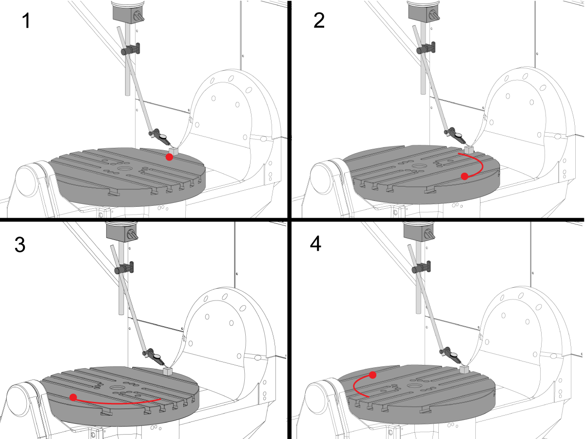
Zero an indicator [1], on a Ground Block [2], 1/2" off the edge at the rear of the platter (Mag-Base on Spindle), with C at 0 Degrees

Rotate C-Axis to 180°.

Move Y axis, and ground block, in Y Axis negative direction until you are 1/2" away from platter edge, and take the perpendicularity measurement

Adjust the shims until the average error is within 0.0005" end to end.

 Note: For unibody trunnions, the shim location under the bearing support may also be used to correct the C-axis to X-Y plane perpendicularity instead of shimming the saddle truck.

Caution: Shim either two front trucks or two rear trucks with the equal shim.

Note: Shim one truck at the time to maintain the X to Y squareness.

Verify the measurements after all bolts are torqued.

Verify the X to Y alignment in Step 2.

8

Set the tool change offsets:

B-axis tool change offset [1]

For Classic Haas Controls, change Parameter 213. 

For Next Generation Controls, go to: Settings>Rotary Tab>Highlight the rotary and press [INSERT], or change Parameter 6.078 (B TOOL CHANGE OFFSET) to set the trunnion (B Axis) parallel to the X Axis.

For models with multipiece trunnion

(NTE 0.001/10"; NTE 0.0020" overall)

For models with unibody trunnion

(NTE 0.0005/10"; NTE 0.0010" overall)

___

C-axis tool change offset [2]

For Classic Haas Controls change Parameter 523.

For Next Generation Control go to: Settings>Rotary Tab> Highlight the rotary and press [INSERT], or change Parameter 7.078 (C TOOL CHANGE OFFSET) to set the table T-slot (C Axis) parallel to the X Axis

For models with multipiece trunnion

(NTE 0.001/10"; NTE 0.0020" overall)

For models with unibody trunnion

(NTE 0.0005/10"; NTE 0.0010" overall)

9

Check C-axis perpendicularity to X/Y plane:

Align the indicator centered over the C-axis bore with the Y-axis at -10.

Jog positive in the Y-axis and align the indicator over the center of the last section of the platter and make a mark at this spot with a washable marker.

Insert 1-2-3 block as shown and set the indicator to zero.

Remove the block and rotate the platter 90 degrees, following the marked spot with the indicator.

Insert block back between the indicator and platter. Note reading.

Repeat the previous two steps, taking readings with the platter at 180, 270 and 360 degrees.

Multi-piece trunnion:  (NTE 0.0005")

Unibody trunnion: (NTE 0.001")

10

Measure the intersection of the B and C axis:

Follow the linked instruction manual to complete this step.

B-Axis and C-Axis intersection Adjustment

11

Align the B-Axis brake disk:

 Note: Do not do this step if you are working on a SS machine.

Operate this code in MDI mode to unclamp the brake:

M11;

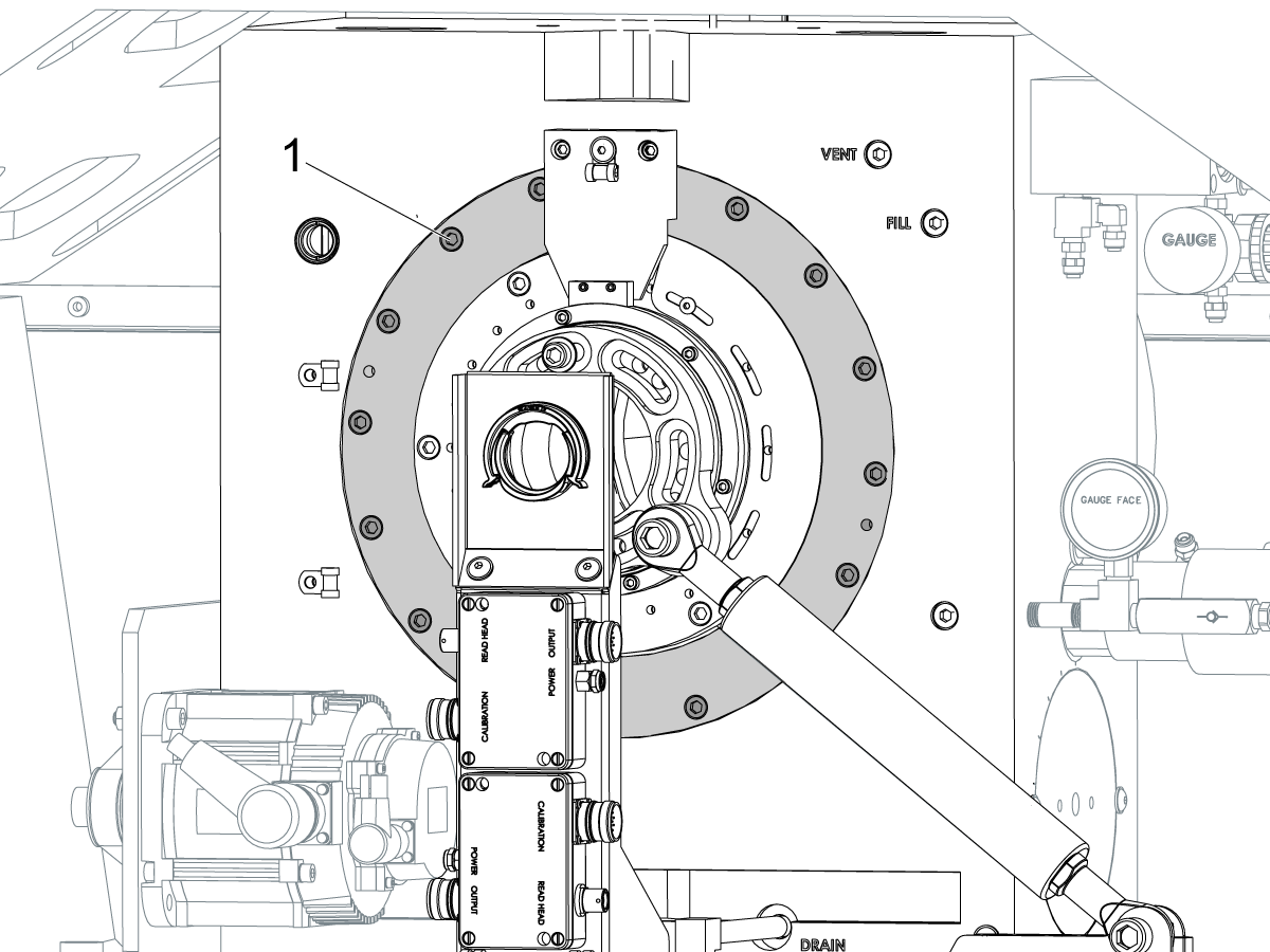
Loosen all of the brake disc bolts [1] and torque them to 5 Ft-lbs (7 Nm).

Operate this code in MDI mode to clamp the brake:

M10;

Wait 10 seconds.

Torque the bolts. Refer to Haas Fastener Torque Specifications.

Set Parameter/Setting Back to Factory Values

Set the Parameter 1314 for CHC / Setting 254 for NGC back to the factory-set value.(Cycle the power to the machine after changing the value.)

Allign and calibrate the WIPS. Wireless Intuitive Probe System (WIPS) - Calibration

Set the Machine Rotary Zero Points. 

  • UMC-750 - MRZP WIPS Offsets Settings - CHC
  • UMC-750 - MRZP WIPS Offsets Settings - NGC

Fill out the complete inspection report:

  • EA0420 UMC-500 Inspection Report
  • EA0373 UMC-750 Inspection Report
  • EA0418 UMC-1000 Inspection Report

Leave the copy of the inspection report with the machine.

If you replaced the B and C axes assembly do the UMC-750 - B-Axis and C-Axis Intersection - Alignment

8.2 Alignment - Indicating Zones

Recently Updated

UMC Alignment Indicating Zones


AD0490

Indicating Zones

1

X-axis Roll

  • First attach tool T-2192 to the side of the spindle.
  • For X-Roll measurement hold the following Y and Z-axis postitions:
    • UMC 500 (Y,Z): -8, -8
    • UMC 750 (Y,Z): -10, -10
    • UMC 1000 (Y,Z): -12, -12
  • Measure X-axis roll (NTE 0.0005" / 10")


2

B-axis to Y-axis Parallelism

  • Zero-Return B and C-axis.
  • Measure the platter runnout in the Y-Axis (NTE: 0.0008" / 10"; 0.0012" / 15")
  • Then measure this same surface with the B-Axis at both -90° and +90°  (NTE: 0.0008" / 10"; 0.0012" / 15")
  • For UMC 500 and 750, measure the full length of the platter
  • For UMC 1000, offset 2” from edge of platter then measure across 20”

3

Y-axis to X-axis Perpendicularity

  • Use jacking screws to make the top surface of the granite parallel to XY plane (NTE: 0.0002")
  • Next, check if Y square to X (NTE 0.0005" / 10")

4

Perpendicularity of X-axis to Z-axis

  • Place granite and precision cylinder on platter in the orientation shown
  • Use jacking screws to set top surface of cylinder parallel to XY-Plane (NTE 0.0002")
  • XY Spindle locations for this step:
    • UMC 500, X = -6, Y = -8
    • UMC 750, X = -10, Y = -10
    • UMC 1000, X = -17, Y = -12
  • Z start position for this measurement:
    • UMC 500, Zstart = Ztop – 2”
    • UMC 750, Zstart = Ztop – 5”
    • UMC 1000, Zstart = Ztop – 7”
  • Ztop is the limit of Z-axis travel in the positive direction (up)
  • From Zstart, measure down 10” along cylinder

5

Perpendicularity of Y-axis to Z-axis

  • Place granite and precision cylinder on platter in the orientation shown
  • Use jacking screws to set top surface of cylinder parallel to XY-Plane (NTE 0.0002")
  • XY Spindle locations for this step:
    • UMC 500, X = -6, Y = -8
    • UMC 750, X = -10, Y = -10
    • UMC 1000, X = -17, Y = -12
  • Z start position for this measurement:
    • UMC 500, Zstart = Ztop – 2”
    • UMC 750, Zstart = Ztop – 5”
    • UMC 1000, Zstart = Ztop – 7”
  • Ztop is the limit of Z-axis travel in the positive direction (up)
  • From Zstart, measure down 10” along cylinder

6

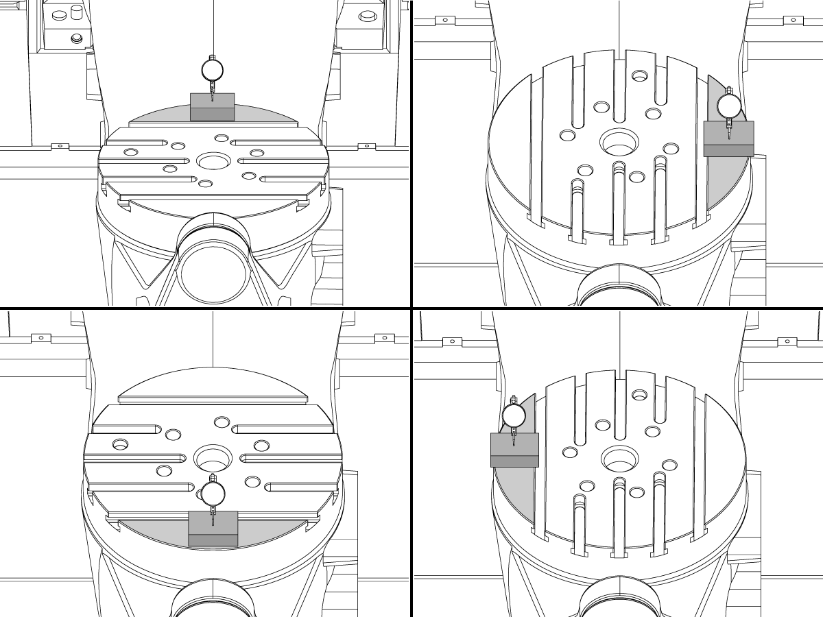
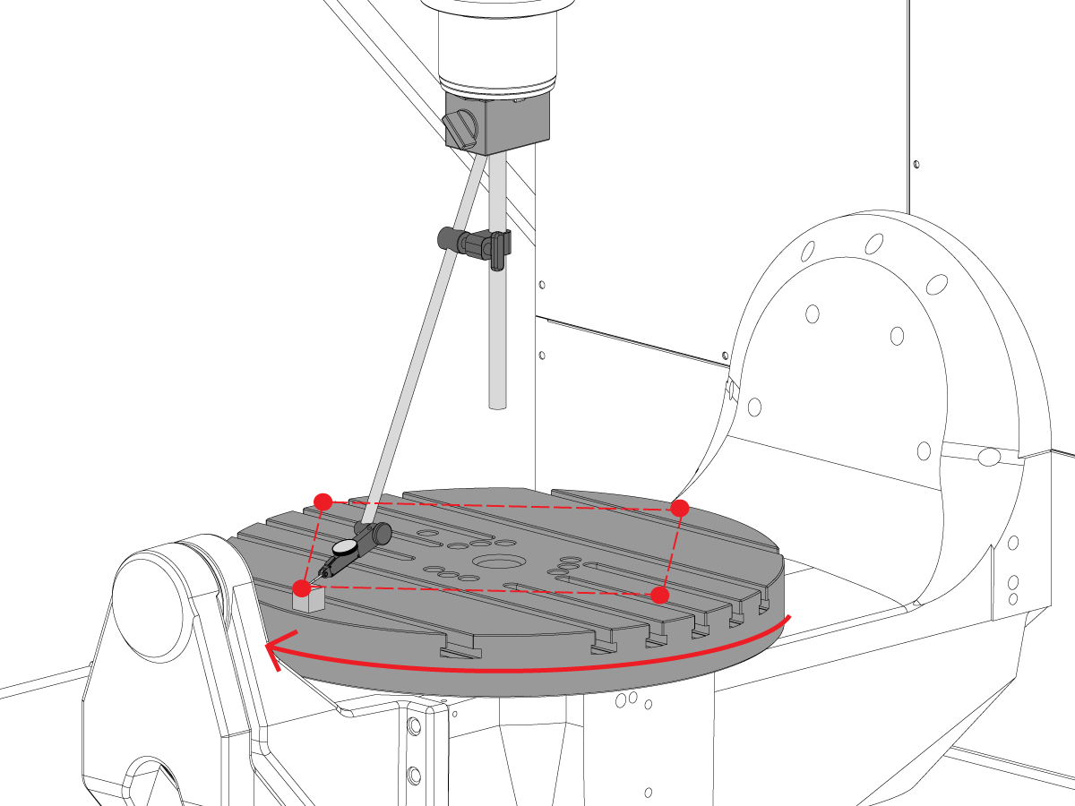
C-Axis Perpendicularity to XY Plane

  • Reposition the mag base on the spindle so it cannot rotate with the spindle.
  • Place precision guage block at the edge of the platter in the 12 o'clock position. 
  • Zero the indicator tip on the gauge block in this position.
  • Rotate the C-axis  90° 
  • Next, jog the spindle in the X and Y-axis to follow the guage block and take a measurement of the same point on the platter. No rotation of the spindle should occur
  • Repeat this 2 more times for a total of 4 positions, 90° apart, at the edge of the pallet as shown. 
  • The difference between 12 and 6 o'clock position measurements determines flatness along the X-Axis (NTE 0.0005")
  • The difference between 3 and 9 o'clock position mesurements determines flatness along the Y-Axis (NTE 0.0005")

7

Platter Face Runout

NOTE: C-Axis brake is off for this step

  • Place precision guage block at the edge of the platter in the 12 o'clock position. 
  • Zero the indicator tip on the gauge block in this position.
  • Rotate the C-axis  90° but, keep the guage block at the 12 o'clock position
  • Take a measurement from the top of the gauge block
  • Repeat this 2 more times for a total of 4 positions, 90° apart, at the edge of the pallet as shown. 
  • Note the total indicated runout. (NTE 0.001")

8

Parallelism of Platter Surface to XY plane

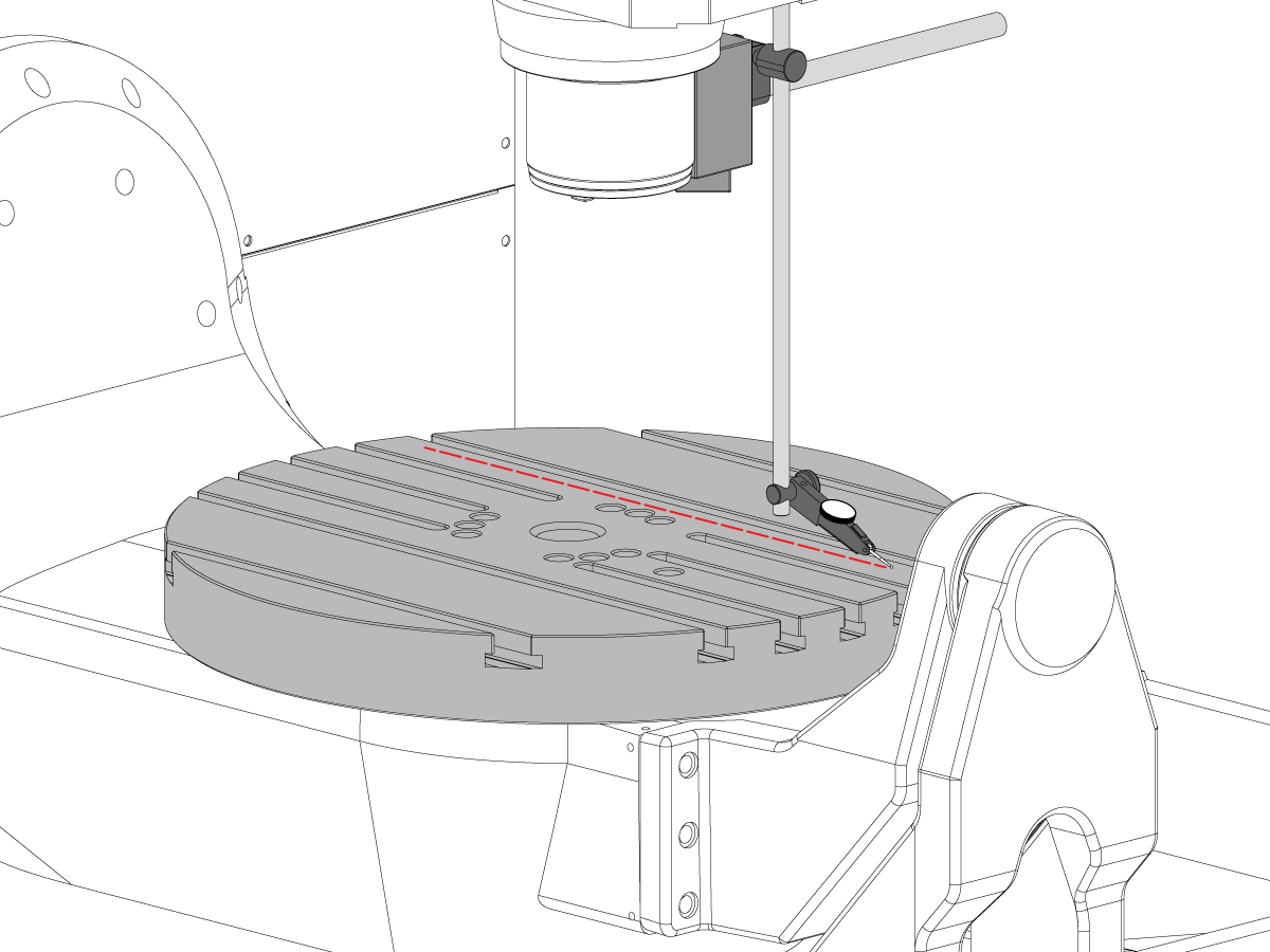
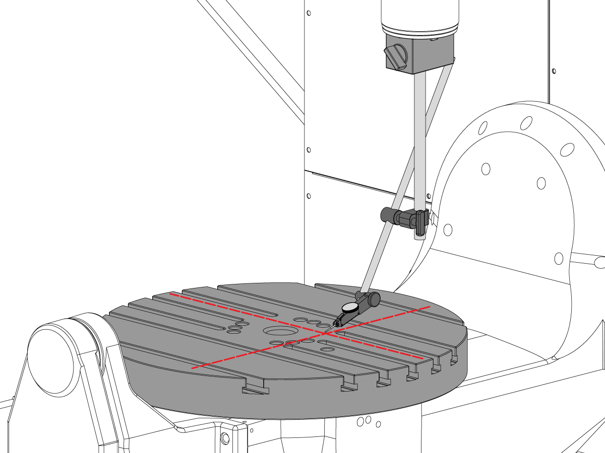
  • Zero-Return the C-axis so the T-slots run parallel to the X-axis
  • Place indicator tip on the platter and jog in the X-axis along the platter to find the X-axis platter parallelism (NTE 0.001” / 10"; 0.0015" / 15")
  • Next jog in the Y-axis along the platter to find the Y-axis platter parallelism (NTE 0.001” / 10"; 0.0015" / 15")

9

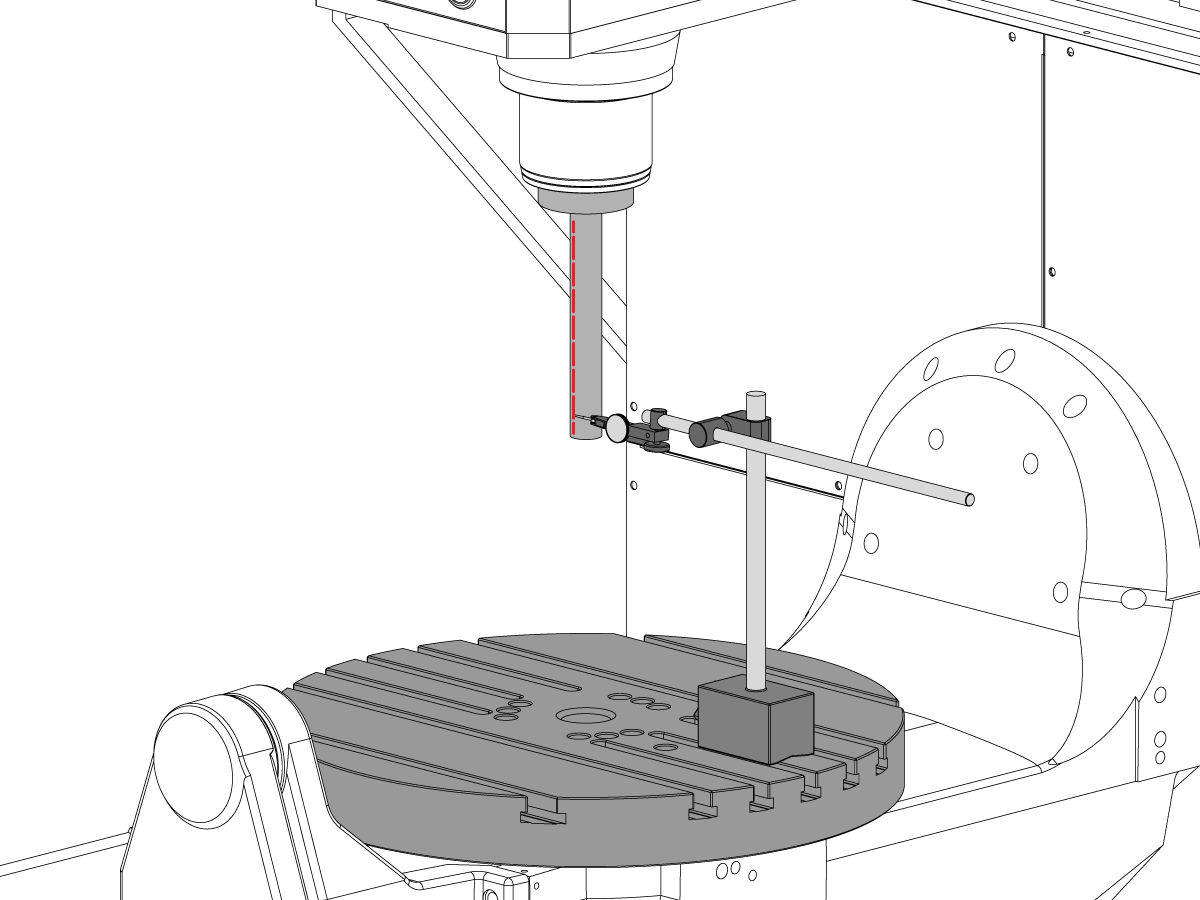
Spindle Runout

  • Center the spindle over the C-Axis bore.
  • Place the mag base on table and insert test bar.
  • Check spindle runout at base of test bar (NTE 0.0005" TIR)
  • Check spindle runout 6" down from the base of the test bar (NTE 0.001" TIR)

10

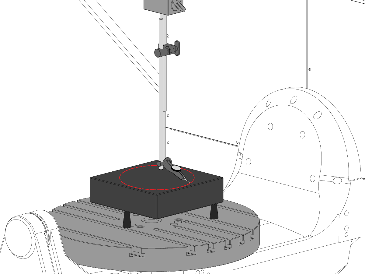
Spindle Centerline Parallelism to Z-axis

  • Use jacking screws to make granite parallel to XY plane in the orientation shown (NTE: 0.0002")
  • Center the spindle over the C-axis platter bore
  • Sweep in a 10" diameter circle
  • Record XZ TIR  (NTE 0.0005")
  • Record YZ TIR  (NTE 0.0005")

11

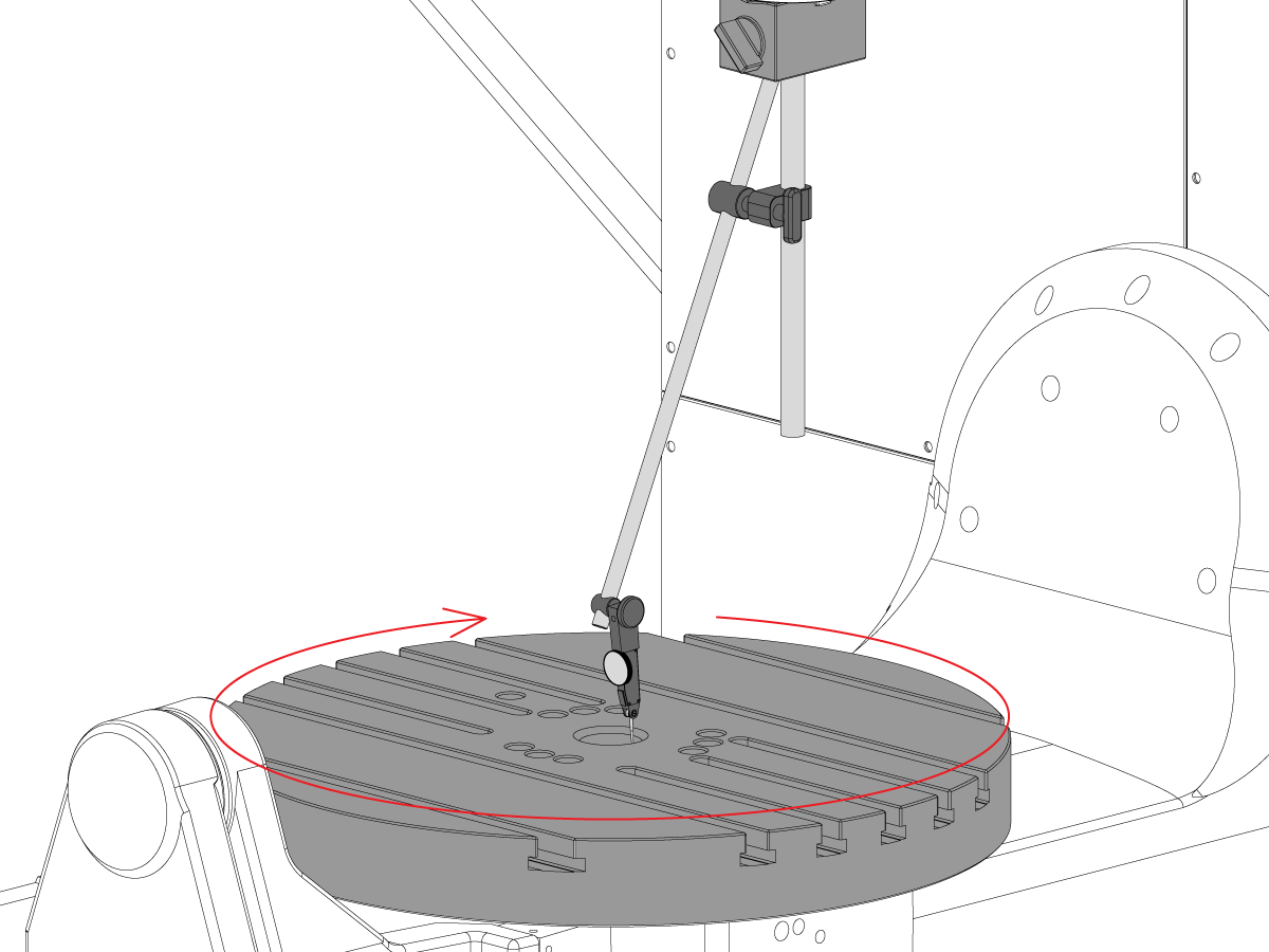
Concentricity of C-Axis Bore

  • Place indicator as show and jog C-axis 360°
  • Record TIR of precision bore (NTE 0.002")

12

Machine Rotary Zero Point

  • Use the VQC Macro Program and probe system to verify the values for the Coldfire parameters or the NGC settings shown below:
    • 255 - MRZP X OFFSET
    • 256 - MRZP Y OFFSET
    • 257 - MRZP Z OFFSET
    • 254 - 5 AXIS ROTARY CENTER POINT DISTANCE
  • For a complete MRZP instruction please see the Haas MRZP WIPS Offset Setting procedure

8.3 Geometry - Troubleshooting

Recently Updated

UMC - Geometry - Troubleshooting Guide


Overview

Before troubleshooting a UMC-750 accuracy or geometry problem, the tech must have a thorough understanding of the following fundamentals:

  • How to level and align the rotary axes of the UMC
  • How to Re-align all of the axes of the machine
  • How to Perform MRZP calibration and a thorough understading of what the associated parameters are, and their effect on the machine
  • An understanding of the machines accuracy capabilities and the ability to reason though the geometric problems
  • B to C axis Intersection Alignment

A problem with UMC-750 machine geometry or accuracy needs to be approached systematically and in the proper sequence. The following information should be adhered to strictly and followed in sequential order.

It is absolutely critical that before any assesment or adjustment is made to the machine geometry that the machine has been checked for proper level and alignment of the rotary axes to the machine

Many errors can be attributed the the machine suffering a crash or problems either with tooling applications or programming issues. Do not attempt to change machine geometry with out completely checking the machines overall level and geometry per the Inspection report. This includes checking the Machine Rotary Zero Point (MRZP).

In the event of a crash there are 4 slip joints on the machine. These areas are the spindle head to the ram, the ram to the saddle, the saddle to the bridge, and the trunnion to the trunnion support.

 Note: none of these joints should ever be shimmed. A machine crash should never change the amount of shims required in the machine from the factory settings.

It is important to remember the Linear accuracy of the machine is 0.0004/10" and the angular accuracy is +/- 15 arc. sec. These tolerances can add up quickly.

Every effort should be exhausted to determine if the machining application is reasonable and within the machine, fixturing, and toolings ability.

Assess Machine Condition

Determine if machine was crashed previously. Review the alarm history; look for physical damage on the sheet metal, table, spindlehead, etc. No matter how "minor" the crash was, it will affect machine's geometry. If the machine has been crashed a full inspection of the machines geometry needs to be performed

Asses the overall condition of the part fixturing and the condition of the cutting tools.

Get full machine backup and error report.

Verify Machine Level and Geometry

Verify machine is level and the rotary axis is aligned to the machine

 Note: do not attempt to make any adjustments to the machine geometry other than adjusting level feet at this time.

If the machine is out of level or the rotary is not aligned, reset level and rotary alignment.

Perform Full geometry inspection noting magnitude and direction of any errors for each axis.

Analyze the inspection report.

If any of the sections of the inspection report is out of tolerance, machine needs to be re-aligned.

Review application

Gather the following information about the part, workholding, and tooling:

  • Which features are out of tolerance, magnitude, direction of the error
  • Is the part machined using 5-axis, 3+2 axis or 3 axis?
  • Review the part and the machining approach
  • Can any of the part accuracy errors be minimized by changing the machining approach?
  • Is the problem a repeatability issue, a size issue, or a geometric issue?
  • Does the Program use TCPC or DWO?
  • Are there any values in the compensation tables?

8.4 Applications - Troubleshooting

Recently Updated

UMC - Applications - Troubleshooting Guide


How to Access

To get the UMC Applications Troubleshooting Guide:

Follow this link Documents and Software | HBC

or

Log on to HBC.HAASCNC.COM

NOTE: Only Haas Certified Service technicians can log into these sites. 

Select the Service tab.

Under Utilities, select Documents and Software.

Select the Applications folder.

8.5 UMC-750 - Shim Kit Checklist

Recently Updated

UMC-750 - Shim Kit Checklist


AD0131

Introduction

This is the Shim Kit Checklist for the following kit:

  • 93-2236 LOANER, SHIM KIT FOR UMC-750

Checklist: Shim-Spacer-Column

Thickness Part # Quantity in kit USED
.02100 20-9358A 2  
0.2105 20-9359A 2  
.02110 20-9383A 2  
0.2115 20-9365A 2  
0.2120 20-9384A 2  
0.2125 20-9385A 2  
0.2130 20-9368A 2  
0.2135 20-9369A 2  
0.2140 20-9386A 2  
0.2145 20-9371A 2  
0.2150 20-9372A 2  
0.2155 20-9387A 2  
0.2160 20-9374A 2  
0.2165 20-9375A 2  
0.2170 20-9376A 2  
0.2175 20-9377A 2  
0.2180 20-9378A 2  
0.2185 20-9379A 2  
0.2190 20-9380A 2  
0.2195 20-9381A 2  
0.2200 20-9382A 2  

Note: Kit Owners Only: Specify the shim thickness when you order replacements. For example, 20-9382 0.2145

Checklist: Horshoe Shims

Thickness Part # Quantity in kit USED
0.0010 59-0240 2  
0.0020 59-0241 2  
0.0030 59-0242 2  

Checklist: Shim-Spacer-Column-Large

Thickness Part # Quantity in kit USED
0.2130 20-6282A 2  
0.2135 20-6283A 2  
0.2140 20-6284A 2  
0.2145 20-6285A 2  
0.2150 20-6286A 2  
0.2155 20-6287A 2  
0.2160 20-6288A 2  
0.2165 20-6289A 2  
0.2170 20-6290A
2  
0.2175 20-6291A 2  
0.2180 20-6294A 2  
0.2185 20-6295A 2  
0.2190 20-6292A 2  
0.2195 20-6293A 2  
0.2200 20-6296A 2  
0.2205 20-6297A 2  
0.2210 20-6277A 2  
0.2215 20-6279A 2  
0.2220 20-6278A 2  
0.2225 20-6298A 2  
0.2230 20-6281A 2  

Note: Kit Owners Only: Specify the shim thickness when you order replacements. For example, 20-6290A 0.2080

RECORD WHICH SHIMS WERE REMOVED FROM THE KIT IN THE USED COLUMN.

RETURN THE CHECK LIST WITH THE SHIM KIT.

RETURN THE ORIGINAL SHIMS IN THE CRATE.

8.6 B/C - Axis Intersection - Alignment

Introduction

This procedure shows you how to measure and align the intersection of the B and C axes.  Before attempting this procedure verify that the machine is level per UMC-750 leveling.

You will need to align the B and C axes after you either:

  • Replace the B and C axes
  • or complete a UMC inspection report and find an issue

The 5‑Axis Rotary Center Distance defines the difference between the rotary centers of rotation: C-Axis Machine Rotory Zero Point (MRZP) and the B-Axis MRZP in the X Axis.

It is possible there is no difference between the C-Axis and the B-Axis MRZP.

  • Classic Haas Control (CHC): Parameter 1314 - Rotary Axes Center Deviation in X
  • Next Generation Control (NGC): Setting 254 - 5 Axis Rotary Center Distance

You will need the following tools:

  • T-2195A UMC Aligment Bar Adapter
  • T-2113 Alignment bar
  • Heat gun and heat resistant gloves

B Axis to XYZ Axes Alignment

How to identify the Multi-Piece and the Unibody trunnion   

1) Multi-Piece trunnion:    UMC machines built approximetely before 11/2022 will have this configuration.

2) Unibody trunnion:    UMC machines built approximetely after 11/2022 will have this configuration.

1

Remove the A-frame trunnion support:

Remove the bolts [1] that secure the A-frame trunnion support [2] to the base and take out the shims between A-frame support and the base.

Rotate the A-frame support [2] counter-clockwise to clear the edge of the base [3].

Pull the A-frame support off the bearings.

 Note: The A-frame support might vacuum lock on the bearings. Use the zip-tie to pry the seal [4] open.

 Caution: To lift the trunnion support, get the aid of another person. The support weighs 85 lbs (39 kg).

2

Measure the B- axis of rotation parallelism to the Y-Z plane:

For a machine with a Classic Haas Control, change Parameter 151:20 (B axis CHK TRAVL LIM) to 0.

For a machine with a Next Generation Control, change Parameter 6.021 (B axis CHK TRAVL LIM) to FALSE.

Measure the parallelism of the platter to the Y-Z plane with the B axis at 90° and then the B axis at -90° as shown in the picture.

Position the Y-Axis in the following starting position:

UMC-500: Y=0, Sweep 15”, 3rd T-Slot Land from the top.

UMC-750/1500-Duo: Y=-1.0, Sweep 18", 3rd T-Slot Land from the Top .

UMC-1250: Y=-1.0, Sweep 28", 3rd T-Slot Land from the Top.

UMC-500PP: Y=-4.0, Sweep 7".

UMC-750PP: Y=-2”, Sweep 15".

UMC-1000PP: Y=-4”, Sweep 15".

Compare the results at B 90° and B-90°. The results should be...

  • Symmetric against the Y-Z plane, positive or negative direction
  • Less than 0.0010"/20"

If the results are symmetric against Y-Z plane, and are less than 0.0010"/20 inches: Go to Step 5.

If the results are symmetric against Y-Z plane, but are more than 0.0010"/20 inches: Go to Step 4.

 Warning: If the results [3] are not symmetric against the Y-Z plane, the B axis rotary needs to be aligned: Go to Step 3.

3

Align the B axis of rotation parallel to the Y-Z plane:

Loosen the (6) bolts [1] that secure the B axis rotary to the base casting.

 Note: Keep the bolts sufficiently snug to control the adjustments.

Adjust the front and rear setscrews [2] until the measurements taken in Step 2 are symmetric against the Y-Z plane.

Torque the (6) bolts [1]. Refer to Haas Fastener Torque Specification.

Verify the measurements in Step 2 after the bolts have been torqued.

4

Align the C Axis of rotation perpendicular to the B Axis of rotation:

Remove the bottom C-Axis access cover.

Loosen the (12) bolts [1] that hold the C Axis body to the B Axis platter face.

Reach the bottom (4) bolts through the C Axis access port.

If the B Axis is symmetric in the positive direction [4], install horseshoe shims [2] of appropriate size behind the top (2) bolts.

If the B Axis is symmetric in the negative direction [5], install horseshoe shims [2] of appropriate size behind the bottom (2) bolts.

Torque the (12) bolts to 80 Ft-lbs (108 Nm).

Cut the excessive shim material off.

Verify the measurements in Step 2 after bolts are torqued.

5

Align the trunnion support shaft co-axial with the B Axis of rotation:

Setup (2) indicators on the outer race of the trunnion support bearing [2] as shown in the picture.

Mark the spot on the outer race where one of the indicator needles is contacting the surface.

After moving the B Axis to 90° or -90° you will align the marked spot with the needle again to exclude the bearing runout error from the measurements.

Take the readings when B is at 90° and B at -90°. Compare the readings. 

 Caution: The B axis brake needs to be clamped when taking the readings.

The deviation between the results when B is at 90° and at -90° needs to be less than 0.001" on each indicator.

 Note: The indicator on the side of the bearing will measure top to bottom alignment and the indicator on the top of the bearing will measure side to side alignment.

____

For models with a multi-piece trunnion

Loosen the (6) bolts [3] on the C Axis body support. Keep the bolts sufficiently snug to control adjustment.

Adjust the (8) set screws [4] until deviation between B at 90° and B at -90° is within 0.001".

Torque the (6) bolts [2] on the C Axis body support to 80 Ft-lbs (108 Nm).

Verify the alignment after the bolts have been torqued.

____

For models with a unibody trunnion

Jog rotary to B90. Set up an indicator on the highlighted surface as shown in the lower diagram .

Rotate B-axis 180 degrees (90 to -90).

Run out (NTE 0.010” TIR).

 Caution: If the measurement exceeds the tolerance then contact support.

6

Install and shim the A-frame trunnion support:

Move the B Axis to 90°.

Setup an indicator [1] against a machined surface of the C Axis body. Set the indicator to 0.

Use plastic zip ties [2] to pry the seal open while installing the A-frame support. This lets unwanted air and grease out of the assembly.

Install the A-frame trunnion support [3] over the bearings.

Remove the cable ties.

Turn the trunnion support clockwise until it is vertical.

 Note: The weight of the A-frame support will cause the trunnion to sag. The amount of sag is measured with the indicator that was previously setup on the side of the C Axis body.

____

For multi-piece trunnions

Adjust the shims [4] between the A-frame support and the base casting to remove the sag until indicator reads 0 again.

When the indicator reading is 0, torque the (4) bolts. Refer to Haas Fastener Torque Specification.

Verify the reading after bolts are torqued. Adjust the shims again if necessary until the indicator reads 0.

____

For models with unibody trunnion

Determine the amount of shim stock [4] needed to raise the Trunnion arm so the indicator reads 0.005".

The indicator [1] value will change once the support is torqued.

With indicator still in place:

  • Torque trunnion support bolts to appropriate values.
  • Check indicator to make sure it reads between the range of

Trunnion arm raised (0.005” to  0.010”).

 Note: For unibody trunnions, the shim location may also be used to correct the C-axis to X-Y plane perpendicularity instead of shimming the saddle trucks.

 Caution: Use equal amount of shims on each side of the A-frame support. Unequal shims will cause the A-frame support to pull the trunnion to the side.

Verify the B Axis of rotation alignment to the Y-Z plane (Step 2). Loosen the bolts and tap the A-frame support side to side if necessary to correct the B axis to Y-Z plane alignment.

7

Set C-axis perpendicular to X/Y plane:

Move the axes to

UMC-750's........X= -10.5" & Y=0."

UMC-1000's......X=-17.0" & Y=-0."

Zero an indicator [1], on a Ground Block [2], 1/2" off the edge at the rear of the platter (Mag-Base on Spindle), with C at 0 Degrees

Rotate C-Axis to 180°.

Move Y axis, and ground block, in Y Axis negative direction until you are 1/2" away from platter edge, and take the perpendicularity measurement

Adjust the shims until the average error is within 0.0005" end to end.

 Note: For unibody trunnions, the shim location under the bearing support may also be used to correct the C-axis to X-Y plane perpendicularity instead of shimming the saddle truck.

Caution: Shim either two front trucks or two rear trucks with the equal shim.

Note: Shim one truck at the time to maintain the X to Y squareness.

Verify the measurements after all bolts are torqued.

Verify the X to Y alignment in Step 2.

8

Set the tool change offsets:

B-axis tool change offset [1]

For Classic Haas Controls, change Parameter 213. 

For Next Generation Controls, go to: Settings>Rotary Tab>Highlight the rotary and press [INSERT], or change Parameter 6.078 (B TOOL CHANGE OFFSET) to set the trunnion (B Axis) parallel to the X Axis.

For models with multipiece trunnion

(NTE 0.001/10"; NTE 0.0020" overall)

For models with unibody trunnion

(NTE 0.0005/10"; NTE 0.0010" overall)

___

C-axis tool change offset [2]

For Classic Haas Controls change Parameter 523.

For Next Generation Control go to: Settings>Rotary Tab> Highlight the rotary and press [INSERT], or change Parameter 7.078 (C TOOL CHANGE OFFSET) to set the table T-slot (C Axis) parallel to the X Axis

For models with multipiece trunnion

(NTE 0.001/10"; NTE 0.0020" overall)

For models with unibody trunnion

(NTE 0.0005/10"; NTE 0.0010" overall)

9

Check C-axis perpendicularity to X/Y plane:

Align the indicator centered over the C-axis bore with the Y-axis at -10.

Jog positive in the Y-axis and align the indicator over the center of the last section of the platter and make a mark at this spot with a washable marker.

Insert 1-2-3 block as shown and set the indicator to zero.

Remove the block and rotate the platter 90 degrees, following the marked spot with the indicator.

Insert block back between the indicator and platter. Note reading.

Repeat the previous two steps, taking readings with the platter at 180, 270 and 360 degrees.

Multi-piece trunnion:  (NTE 0.0005")

Unibody trunnion: (NTE 0.001")

10

Measure the intersection of the B and C axis:

Follow the linked instruction manual to complete this step.

B-Axis and C-Axis intersection Adjustment

11

Align the B-Axis brake disk:

 Note: Do not do this step if you are working on a SS machine.

Operate this code in MDI mode to unclamp the brake:

M11;

Loosen all of the brake disc bolts [1] and torque them to 5 Ft-lbs (7 Nm).

Operate this code in MDI mode to clamp the brake:

M10;

Wait 10 seconds.

Torque the bolts. Refer to Haas Fastener Torque Specifications.

B Axis to C Axis Intersection Tool Setup

1

Install the B Axis and C Axis intersection tool:

Jog the C Axis to 0°.

Push [EMERGENCY STOP].

Clean the table.

Guide the shaft of the adapter [1] while you slowly lower it into the center bore.

Attach the adapter to the table with (2) screws [4] and (2) T-nuts.

Attach the alignment bar [2] to the adapter with (3) screws [3].

Snug the (3) screws to allow for adjustments in the next step.

2

Align the B/C intersection tool with the C Axis:

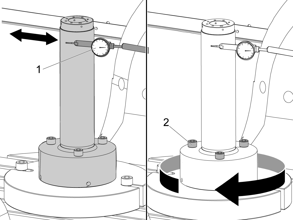
Put an indicator on the front side of the alignment bar near the base.

Release the [EMERGENCY STOP]. Push [RESET] to clear any alarms.

Jog across the tool in the X Axis to find the high spot.

Set the indicator to 0.

Jog the C Axis 360°.

Lightly tap the base with a rubber mallet to adjust the radial error on the alignment bar.

Note: Adjust the alignment bar to half of the measured error, because you are measuring the diameter error.

Jog the C Axis 360°.

When correctly adjusted the radial error is less than 0.0002" (0.005 mm).

3

Check the B/C intersection:

Center the indicator [1] on the front side of the alignment bar near the top of the cylinder.

Jog across the tool in the X Axis to find the high spot.

Zero the indicator.

Jog the C Axis 360°.

Turn the (3) screws [2] on the alignment bar to adjust the runout.

Jog the C Axis 360°.

When correctly adjusted the radial error is less than 0.0002" (0.005 mm).

Repeat Step 2 and verify the alignment did not change.

B Axis to C Axis Intersection Adjustment

1

Set Parameter 151:20 (B-Axis CK Travel Limit) to 0.

Change CHC Parameter 1314 (ROTARY AXIS CENTER DEVIATION IN X) or  NGC Setting 254 (5-Axis Rotary Center Distance) to 0.

Push [ZERO RETURN]. Then push [ALL].

Jog the B Axis to -90°.

Note: The rotary positions are for reference only.

Put an indicator [1] on top of the alignment bar.

Jog in the Y Axis to find the high point.

Set the indicator to 0.

Jog across the alignment bar in the X Axis [2].

Jog the B Axis to adjust the alignment bar parallel to the X plane.

Set the indicator to 0.

Jog the Y Axis to 0.

Caution: Make sure the indicator assembly is clear of the B Axis movement.

 Caution: Do not move the Z Axis.

2

Jog the B Axis to +90°.

 Caution: Make sure the indicator assembly is clear of the B Axis movement.

Jog the Y Axis [1] to find the high point on the alignment bar.

Note: Do not set the indicator to 0.

Jog across the alignment bar in the X Axis.

Jog the B Axis to adjust the alignment bar parallel [2] to the X plane.

When the alignment bar is parallel to the X plane, the indicator reading is the change needed in the Z Axis (∆Z=indicator reading).

Record the value shown on the indicator. In this example the indicator now shows 0.0015". ∆Z is 0.0015".

3

Do these calculations to get the value for CHC Parameter 1314 or NGC Setting 254. (In this example the difference in readings for the B-C intersection (∆Z) is 0.0015".):

  • ∆Z / 2 x 10,000 = CHC Parameter 1314 / NGC Setting 254
  • 0.0015 / 2 = 0.00075
  • Round down to 4 decimal places: 0.00075 = 0.0007 (NGC Setting 254)
  • 0.0007 x 10,000 = 7 (CHC Parameter 1314)

Set Parameter CHC Parameter 1314 (Rotary Axes Center Deviation in X) or NGC Setting 254 (5-Axis Rotary Center Distance), to the calculated value.

In this example, set parameter CHC Parameter 1314 to 7 or NGC Setting 254 to 0.0007.

Cycle the power to save CHC Parameter 1314 or NGC Setting 254.

Repeat Steps 1-3 to verify that the value for ∆Z is less than 0.0002" (0.005 mm).

4

Jog the B Axis to the home position.

Set parameter 151:20 (B-Axis CK Travel Limit) to 1.

Make sure the MRZP offsets are correct.

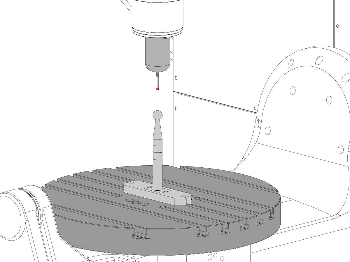
Calibrate WIPS per Wireless Intuitive Probe System (WIPS) - Calibration.

Complete an inspection report. Refer to UMC-750 Inspection Report.

Recently Viewed Items

You Have No Recently Viewed Items Yet

Feedback
Haas Logo

美元价格不包括关税、报关费用、保险费、增值税及运费。
USD prices DO NOT include customs duty, customs fees, insurance, VAT, or freight.

人民币价格包含关税、报关费用、货运保险和增值税, 但不包括运费。
CNY prices include customs duty, customs fees, insurance, and VAT. DOES NOT include freight.

Haas Delivered Price

This price includes shipping cost, export and import duties, insurance, and any other expenses incurred during shipping to a location in France agreed with you as a buyer. No other mandatory costs can be added to the delivery of a Haas CNC Product.

KEEP UP WITH THE LATEST HAAS TIPS AND TECHNOLOGY...

Sign up now!   

HAAS TOOLING ACCEPTS THE FOLLOWING:

  • Service & Support
  • Owners
  • Request Service
  • Operator Manuals
  • Haas Parts
  • Rotary Repair Request
  • Pre-Install Guides
  • Shopping Tools
  • Build & Price a New Haas
  • Available Inventory
  • The Haas Price List
  • CNCA Financing
  • About Haas
  • DNSH Statement
  • Careers
  • Certifications & Safety
  • Contact Us
  • History
  • Terms & Conditions
  • Haas Tooling Terms & Conditions
  • Privacy
  • Warranty
  • Haas Community
  • Haas Certification Program
  • Haas Motorsports
  • Gene Haas Foundation
  • Haas Technical Education Community
  • Events
  • Join the Conversation
  • Facebook
  • X
  • Flickr
  • YouTube
  • LinkedIn
  • Instagram
  • TikTok
© 2025 Haas Automation, Inc – CNC Machine Tools

This site is protected by reCAPTCHA and the Google Privacy Policy and Terms of Service apply.

2800 Sturgis Rd., Oxnard, CA 93030
Toll Free: (888) 817-4446 / Fax: 805-278-8554