-
stroje
-
Vertikálne obrábacie centrá
Vertikálne obrábacie centrá
-
Viacosové riešenia
Viacosové riešenia
-
Sústruhy
Sústruhy
-
Horizontálne obrábacie centrá
Horizontálne obrábacie centrá
-
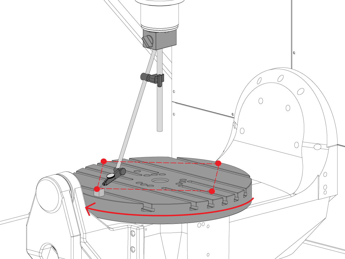
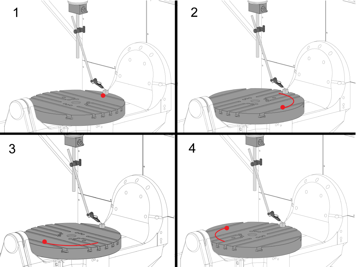
Otočné zariadenia a deličky
Otočné zariadenia a deličky
-
Systémy automatizácie
Systémy automatizácie
-
Stolné stroje
Stolné stroje
-
Vybavenie dielne
Vybavenie dielne
-
Výrobné stroje
Výrobné stroje
NÁKUPNÉ NÁSTROJECHCETE SA PORADIŤ?Na vaše otázky vám odpovedia a tými najlepšími alternatívami vás prevedú v podnikovej predajni spoločnosti Haas.
CONTACT YOUR DISTRIBUTOR > -
Vertikálne obrábacie centrá
-
Voliteľné položky
-
 Vretená
Vretená
Vretená -
 Meniče nástrojov
Meniče nástrojov
Meniče nástrojov -
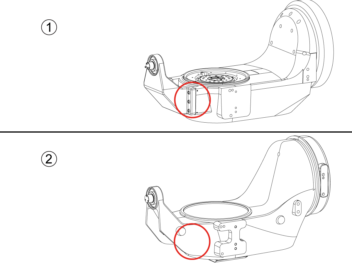
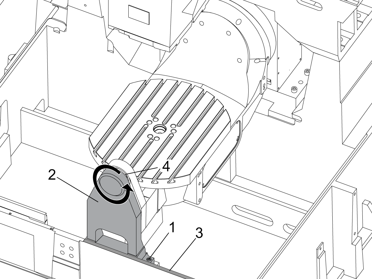
 4. | 5. os
4. | 5. os
4. | 5. os -
 Revolvery a poháňané nástroje
Revolvery a poháňané nástroje
Revolvery a poháňané nástroje -
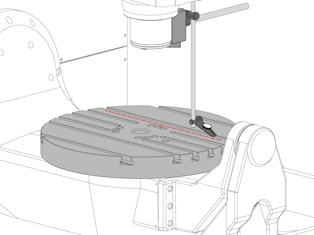
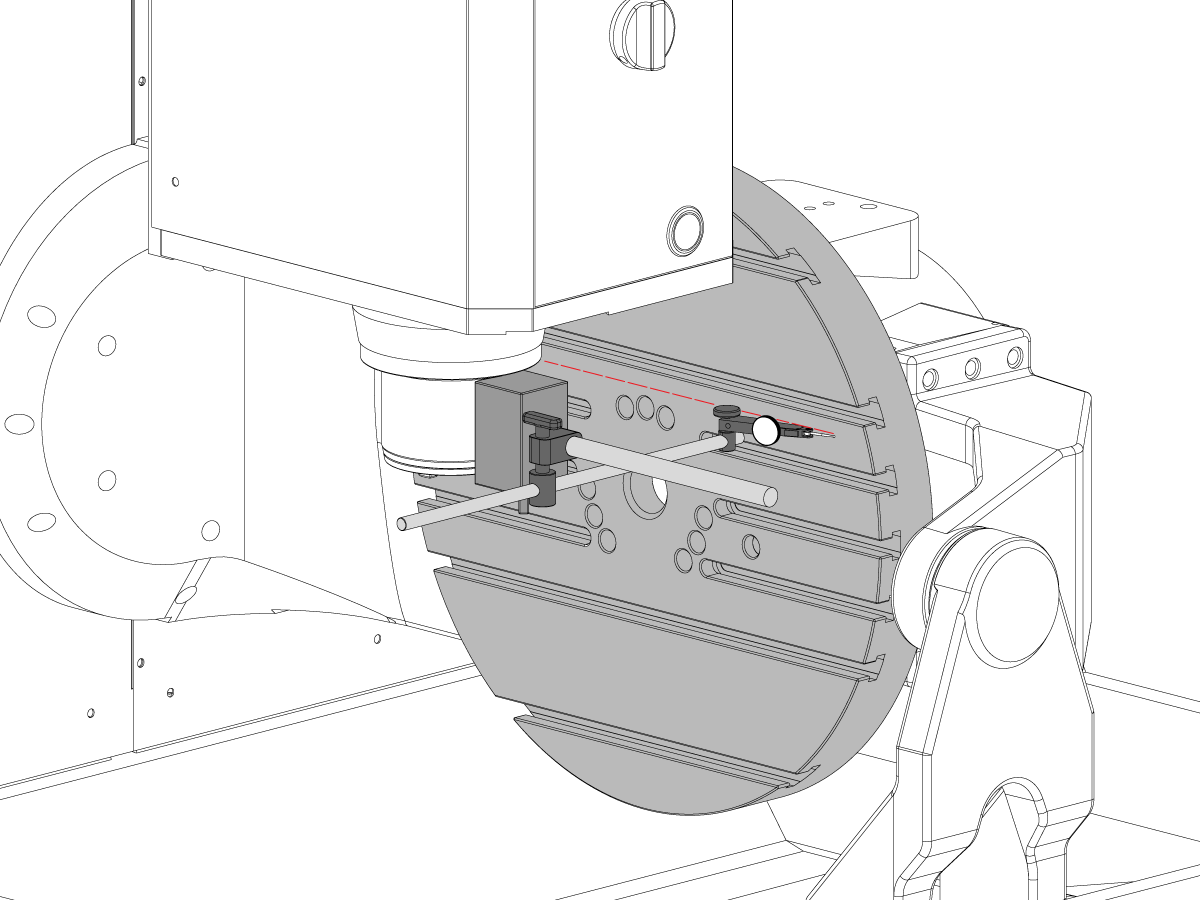
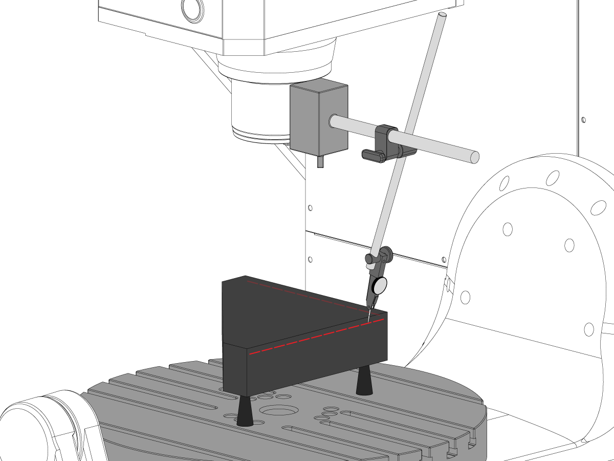
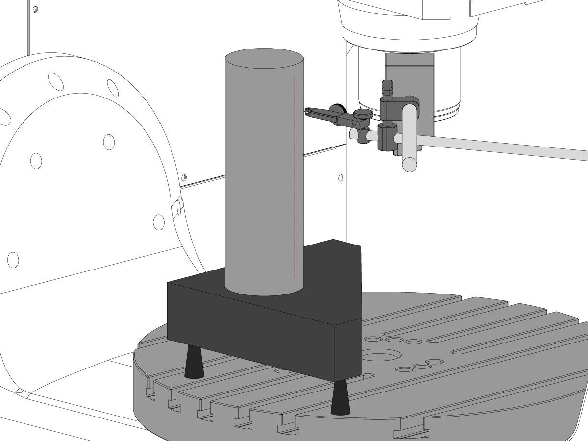
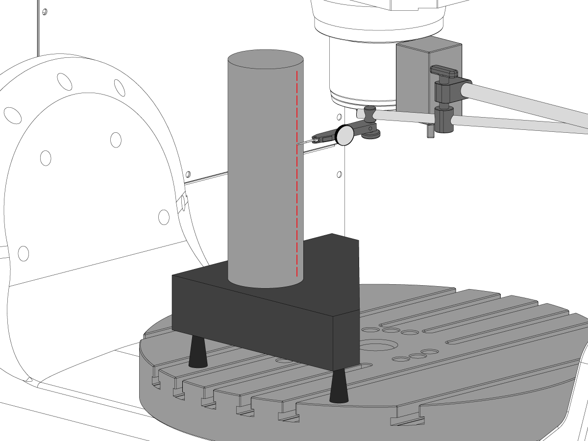
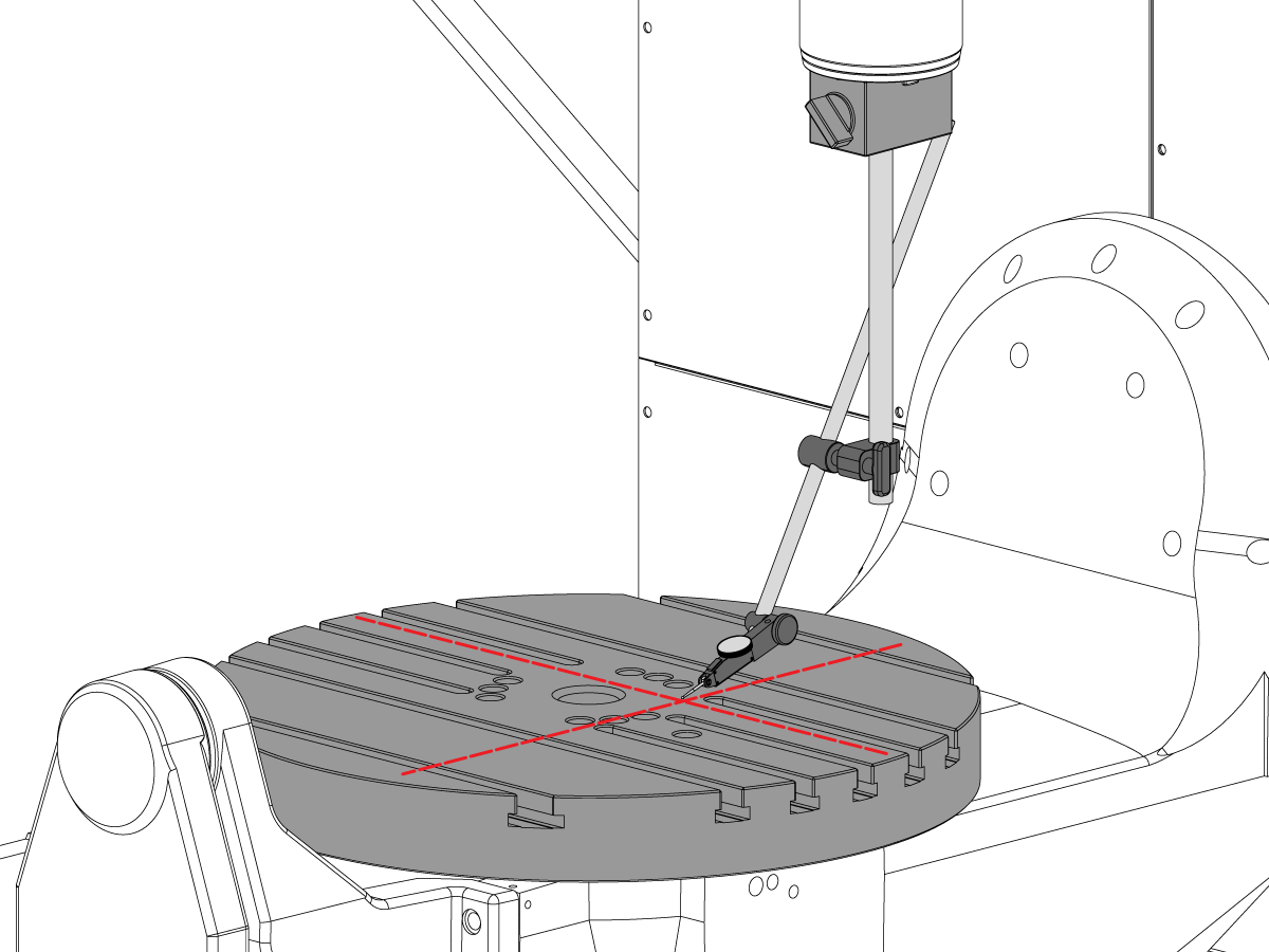
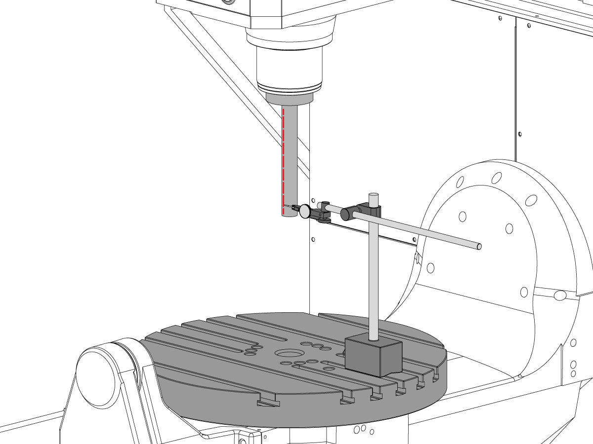
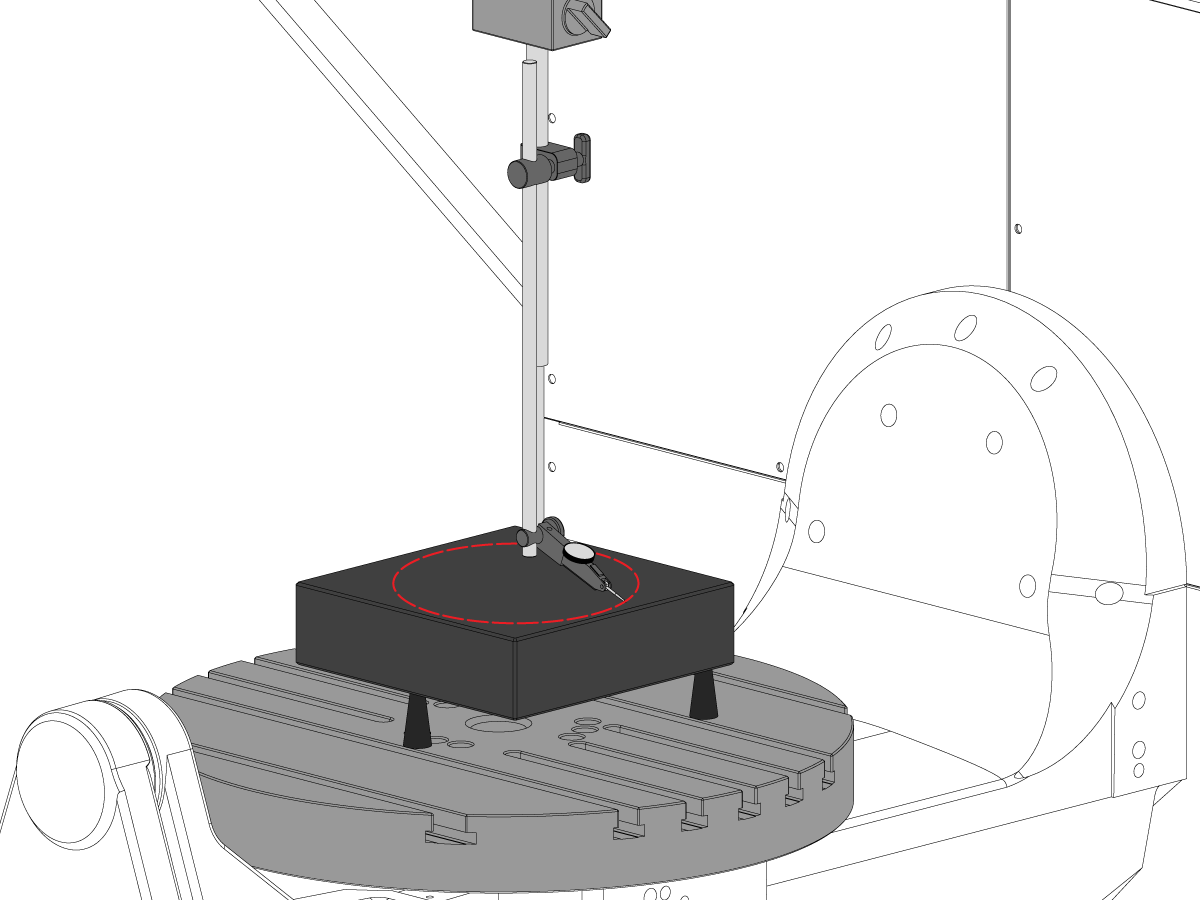
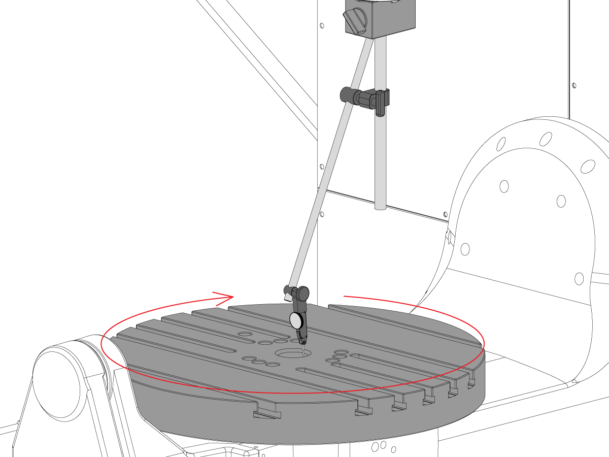
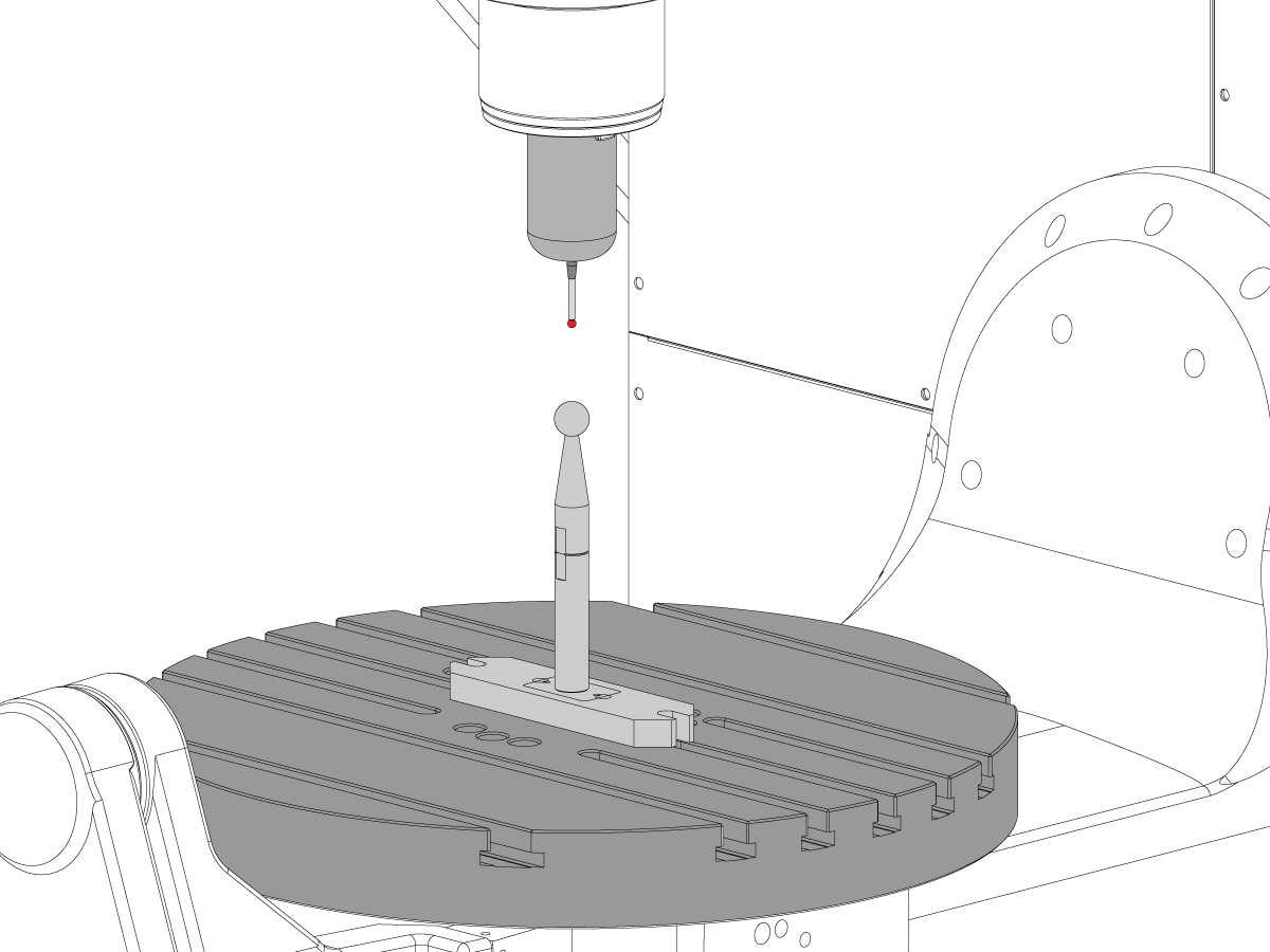
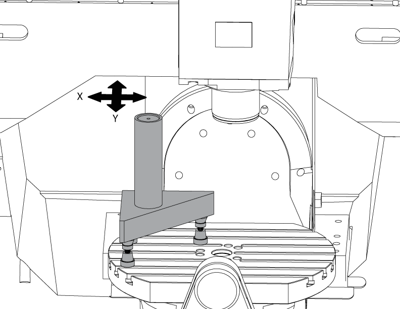
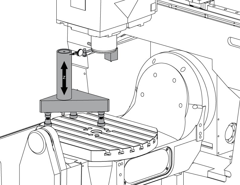
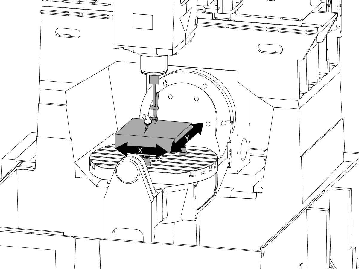
 Snímanie
Snímanie
Snímanie -
 Manažment triesok a chladiacej kvapaliny
Manažment triesok a chladiacej kvapaliny
Manažment triesok a chladiacej kvapaliny -
 Riadenie Haas
Riadenie Haas
Riadenie Haas -
 Doplnková výbava
Doplnková výbava
Doplnková výbava -
 Nástroje a upnutie
Nástroje a upnutie
Nástroje a upnutie -
 Upnutie obrobku
Upnutie obrobku
Upnutie obrobku -
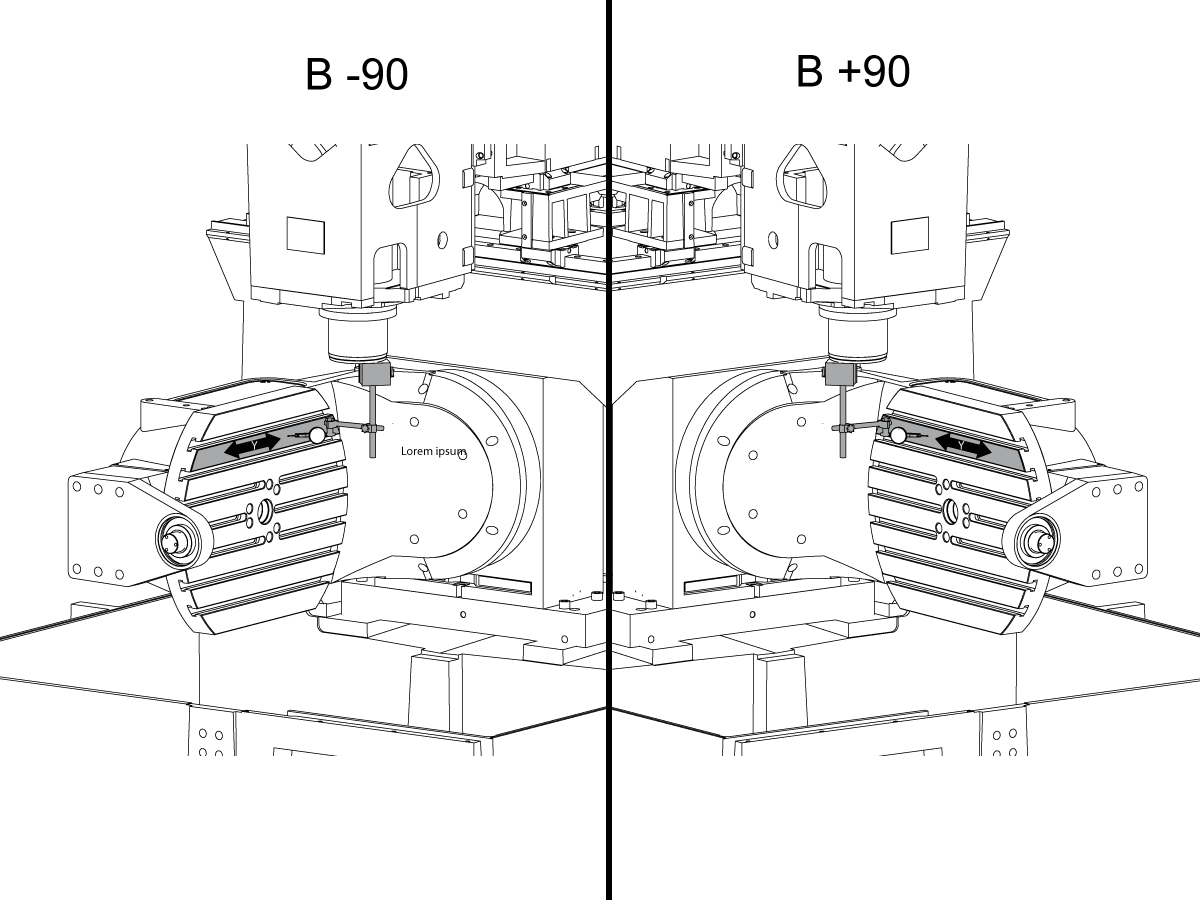
 5-osové riešenia
5-osové riešenia
5-osové riešenia -
 Automatizácia
Automatizácia
Automatizácia
NÁKUPNÉ NÁSTROJECHCETE SA PORADIŤ?Na vaše otázky vám odpovedia a tými najlepšími alternatívami vás prevedú v podnikovej predajni spoločnosti Haas.
CONTACT YOUR DISTRIBUTOR > -
-
Why Haas
Spoznajte zmenu vďaka spoločnosti Haas
-
Servis
- Videá
-
-
HFO Slovakia
HFO Slovakia
NÁKUPNÉ NÁSTROJECHCETE SA PORADIŤ?Na vaše otázky vám odpovedia a tými najlepšími alternatívami vás prevedú v podnikovej predajni spoločnosti Haas.
CONTACT YOUR DISTRIBUTOR > -


.png)