

/2026-04-VOP-SquareComponent.jpg/_jcr_content/renditions/cq5dam.thumbnail.319.319.png) 增值选件套
增值选件套
 主轴
主轴
 刀库
刀库
 第 4 轴 |第 5 轴
 刀塔和动力刀
 探测
探测
 切屑和冷却液管理
 Haas 控制系统
 产品选项
产品选项
 刀具和夹具
刀具和夹具
 工件夹具
工件夹具
 5 轴解决方案
 自动化
自动化


在开始记录之前,工厂设置以下参数或设置的值。在进行调整时,您需要将其设置为零,然后在完成时将其重置为原始值。该值可以是正数或负值。
需要工具和套件:
单击链接以查看 UMC-750 调平和对齐 视频。
* : 仅用于 Pre-Reboot 系列。
设置机器高度:
将 X 轴和 Y 轴旋转到"主页"位置。
松开中间调平螺钉 [2 和 5],使其不支持任何重量。
使用 4 个角调平螺钉将机器高度设置为离地 3" (76.2 mm)。
粗糙的机器水平:
将调平螺钉#4向上。
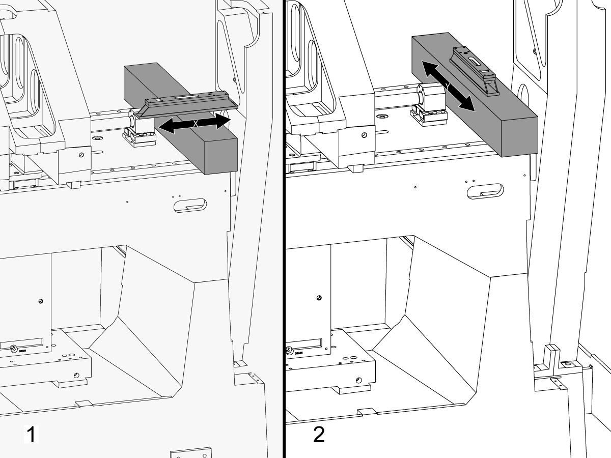
将花岗岩穿过 X 轴线性导轨,靠近 X 轴滚珠丝杠轴承支架。
在与 X 轴平行的花岗岩顶部设置机械师水平。[1]
调整调平螺钉#6,直到机器以 X 轴调平。
在垂直于 X 轴的花岗岩顶部设置机械师水平。[2]
调整调平螺钉#3,直到机床在 Y 轴中调平。
将调平螺钉#4向下转动,直到与调平垫接触。

调整 X 轴辊:
使用 T-2181 组装 T-2192。
将 Z 轴旋转到行驶中间。
将 T-2192 放在主轴的侧面。
确保 T-2181 上的气泡在可读范围内。
如果不是,松开将 T-2192 固定到磁性底座的螺栓,并根据需要移动适配器。
将 X 轴侧向侧旋转并测量 X 轴滚动。在行驶的中心位置、中间位置和终点获取读数。
调整调平螺钉#4 ininininin 之间在行驶位置的读数与行驶结束时的读数之间没有偏差。
注意:T-2181 上的气泡不必位于小瓶中间。它只需要在可读的范围内。
设置中间调平螺钉:
向下转动中间调平螺钉,直到它们与调平垫接触,然后将其再转动 45°。
验证 X 轴辊。调整中间调平螺钉以校正 X 轴辊。
使鞍座表面与 X 轴运动平行:
通过点动 X 轴,扫描鞍座前部 [1] 的加工表面。
松开固定鞍座的螺栓到 X 轴卡车 [2],并在 0.001 内对齐与 X 轴运动平行的鞍座面" 如果需要。
拧紧螺栓。请参阅 Haas 紧固件扭矩规格。

将垂直于 X 轴的 Y 轴对齐:
在机械手千斤顶上的 C 轴盘片左侧设置三方形花岗岩。
设置与 X 轴平行的三方形花岗岩的背面。NTE 0.0001"/10"
沿 X 轴和 Y 轴扫描三方形花岗岩的顶部。
调整机械手千斤顶,直到三方形花岗岩的顶面与 X-Y 平面 NTE 0.0005 平行".
验证花岗岩的背面是否与 X 轴平行。NTE 0.0001"/10".
松开将 Y 轴卡车固定到鞍座上的螺栓,并将垂直于 X 轴的 Y 轴对齐。NTE 0.0005"/10"
拧紧螺栓。请参阅 Haas 紧固件扭矩规格。
拧紧螺栓后,验证 X 轴是否垂直于 NTE 0.0005"/10"。
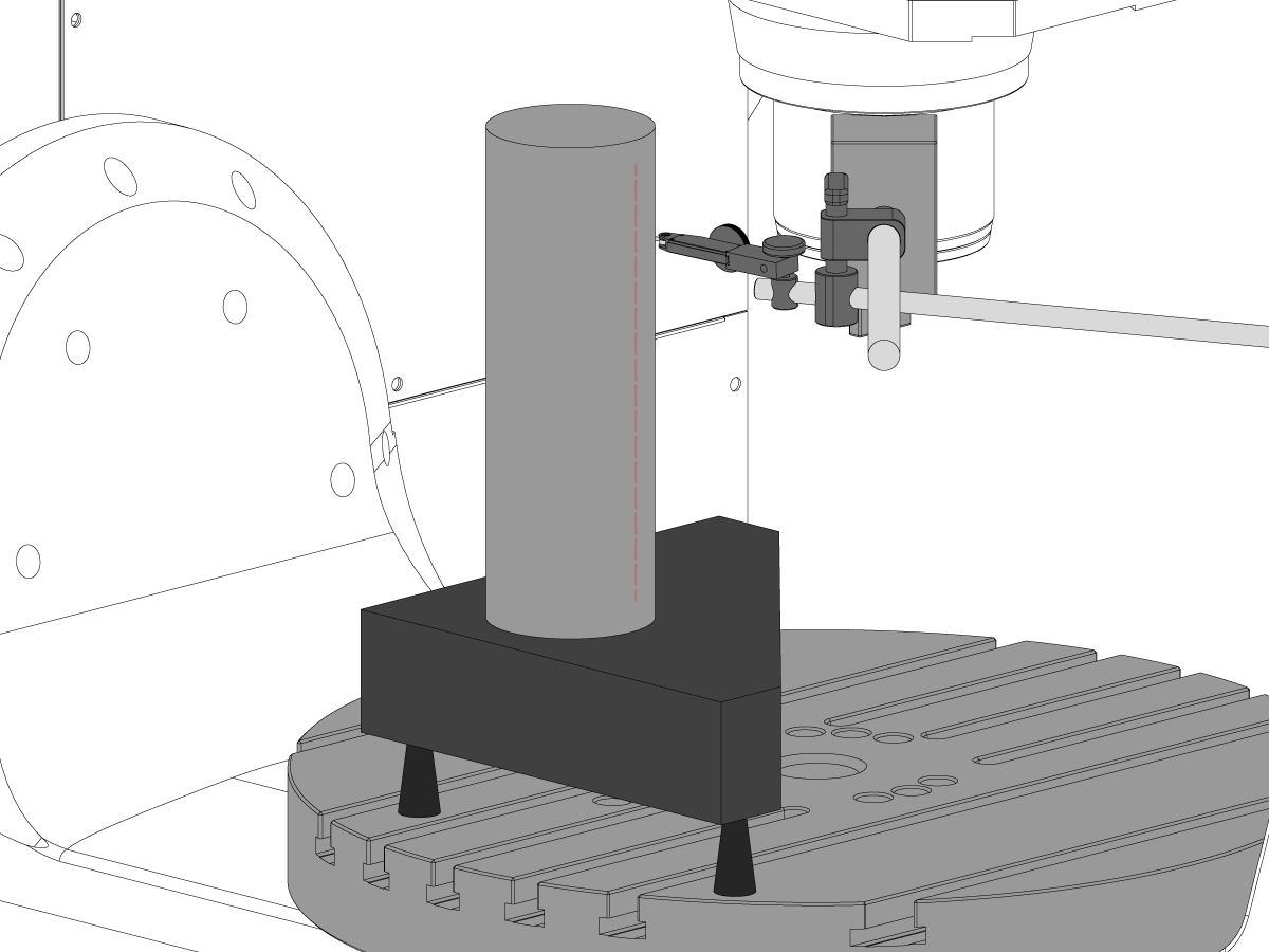
设置气缸。
如图所示,在三块石头上放置一个圆柱体。
通过调整机械手千斤顶,将平行于 X-Y 平面 NTE 0.0001 的圆柱体顶面对齐"。
将机器转向以下位置:
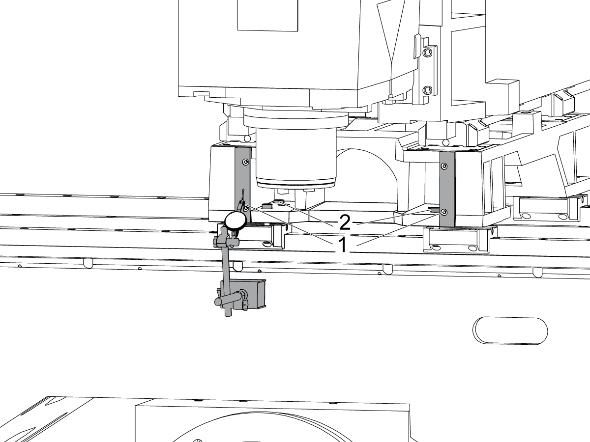
将垂直于 X 轴的 Z 轴对齐:
将 Z 轴卡车上的一个顶角螺栓替换为 T-2193A *,以旋转主轴头。
沿 Z 轴指示圆柱体的一侧。
松开将 Z 轴车固定到冲压上的螺栓。
通过左右摆动主轴头,校准 Z 轴垂直于 X 轴 NTE 0.0005"/10"。
拧紧螺栓。请参阅 Haas 紧固件扭矩规格。
拧紧螺栓后,验证 Z 轴是否垂直于 X 轴。
校准完成后,用螺栓更换 T-2193A *
* : 仅用于 Pre-Reboot 系列。

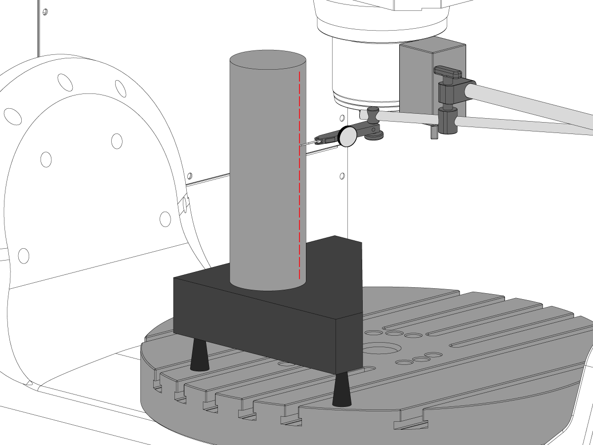
将垂直于 Y 轴的 Z 轴对齐:
沿 Z 轴指示气缸的前部。
在 Z 轴架和臂之间加上垫片,使 Z 轴垂直于 Y 轴 NTE 0.0005"/10"。
注意: 在两个架的顶部或底部加上相同数量的垫片。
拧紧螺栓。请参阅 Haas 紧固件扭矩规格。
拧紧螺栓后,验证 Z 轴是否垂直于 Y 和 X 轴。

对齐和拧紧 Y 和 Z 轴滚珠螺母外壳:
松开将滚珠螺母固定到壳体上的螺栓和螺栓,将壳体固定到铸件上。
先将固定球壳壳壳的螺栓固定到铸件上,然后将固定球螺母的螺栓固定到壳体上。
使用"旋转锁定"功能来回运行轴完全行程。
注意: 请勿使用手轮或快速移动。
拧紧螺栓。请参阅 Haas 紧固件扭矩规格。
Y 轴螺母壳体可在机器后部检修,冲压一直朝机器前部点动。
Z 轴螺母壳体可以从机器前部检修,主轴头一直向下点动。
注意:需要拆下主轴电机护罩才能进入 Z 轴滚珠壳壳壳体。
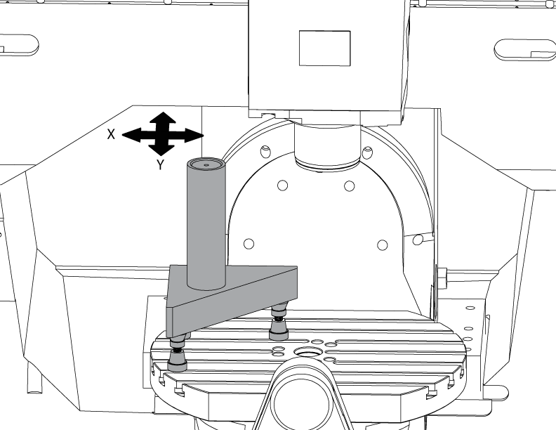
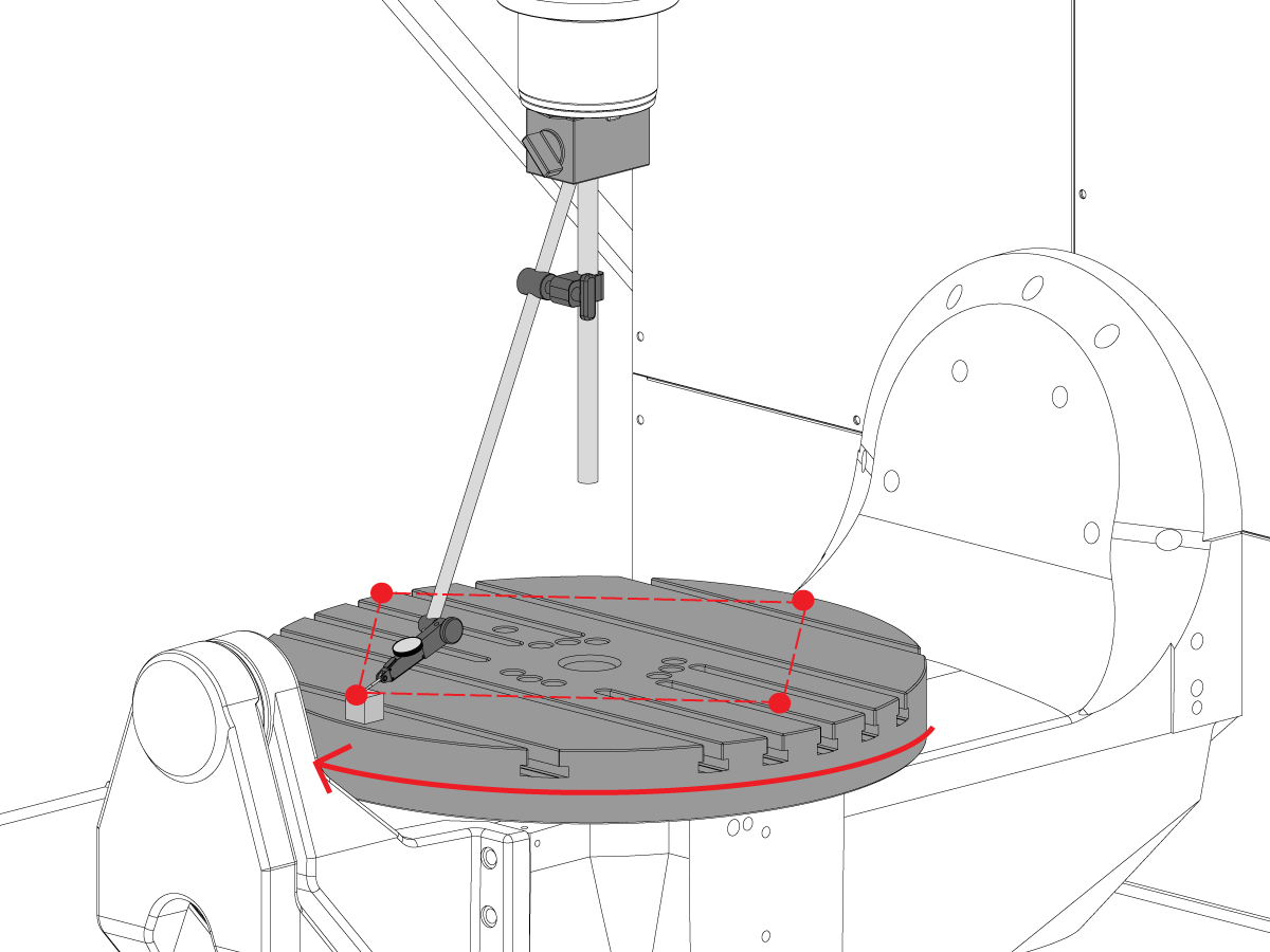
设置花岗岩:
设置机械千斤顶和花岗岩在C轴盘片中间如图所示。
通过调整机械手千斤顶高度 NTE 0.0001,使花岗岩的顶部表面与 X-Y 平面平行".
将主轴放在盘片的中心上。

将主轴电车到 X-Y 平面:
将指示器放在主轴上。
每旋转 90° 时,在花岗岩顶部进行测量。
松开主轴头底板中的 (6) 个螺栓。
添加或拆下主轴头铸件和底板之间的垫片,将主轴移至 X-Y 平面 NTE 0.0005"/10"。
注意:使用厚度不相等的垫片 [1] 更改底板的角度。
当在规格范围内扫描时,拧紧 (6) 螺栓。请参阅 Haas 紧固件扭矩规格。
拧紧螺栓后,验证主轴调整。
How to identify the Multi-Piece and the Unibody trunnion
1) Multi-Piece trunnion: UMC machines built approximetely before 11/2022 will have this configuration.
2) Unibody trunnion: UMC machines built approximetely after 11/2022 will have this configuration.
Remove the A-frame trunnion support:
Remove the bolts [1] that secure the A-frame trunnion support [2] to the base and take out the shims between A-frame support and the base.
Rotate the A-frame support [2] counter-clockwise to clear the edge of the base [3].
Pull the A-frame support off the bearings.
Note: The A-frame support might vacuum lock on the bearings. Use the zip-tie to pry the seal [4] open.
Caution: To lift the trunnion support, get the aid of another person. The support weighs 85 lbs (39 kg).
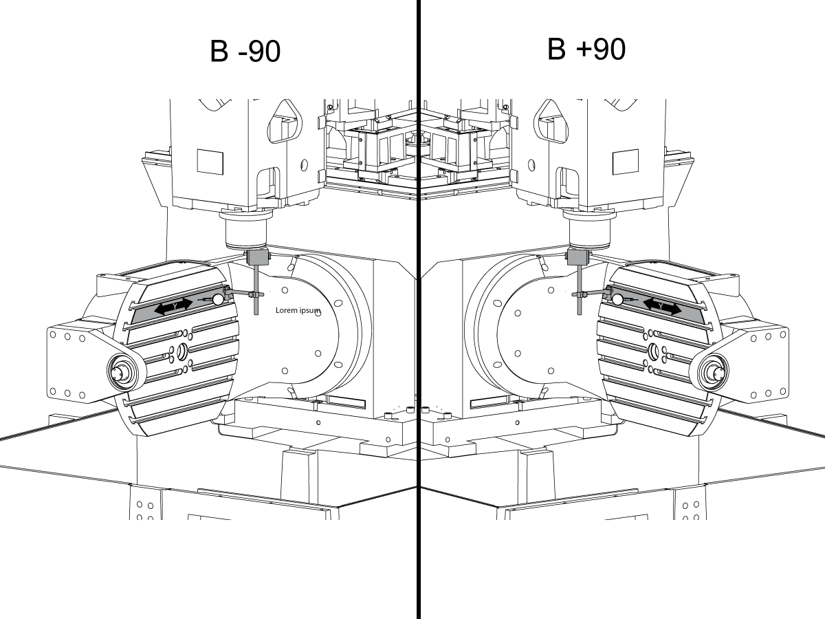
Measure the B- axis of rotation parallelism to the Y-Z plane:
For a machine with a Classic Haas Control, change Parameter 151:20 (B axis CHK TRAVL LIM) to 0.
For a machine with a Next Generation Control, change Parameter 6.021 (B axis CHK TRAVL LIM) to FALSE.
Measure the parallelism of the platter to the Y-Z plane with the B axis at 90° and then the B axis at -90° as shown in the picture.
Position the Y-Axis in the following starting position:
UMC-500: Y=0, Sweep 15”, 3rd T-Slot Land from the top.
UMC-750/1500-Duo: Y=-1.0, Sweep 18", 3rd T-Slot Land from the Top .
UMC-1250: Y=-1.0, Sweep 28", 3rd T-Slot Land from the Top.
UMC-500PP: Y=-4.0, Sweep 7".
UMC-750PP: Y=-2”, Sweep 15".
UMC-1000PP: Y=-4”, Sweep 15".
Compare the results at B 90° and B-90°. The results should be...
If the results are symmetric against Y-Z plane, and are less than 0.0010"/20 inches: Go to Step 5.
If the results are symmetric against Y-Z plane, but are more than 0.0010"/20 inches: Go to Step 4.
Warning: If the results [3] are not symmetric against the Y-Z plane, the B axis rotary needs to be aligned: Go to Step 3.

Align the B axis of rotation parallel to the Y-Z plane:
Loosen the (6) bolts [1] that secure the B axis rotary to the base casting.
Note: Keep the bolts sufficiently snug to control the adjustments.
Adjust the front and rear setscrews [2] until the measurements taken in Step 2 are symmetric against the Y-Z plane.
Torque the (6) bolts [1]. Refer to Haas Fastener Torque Specification.
Verify the measurements in Step 2 after the bolts have been torqued.
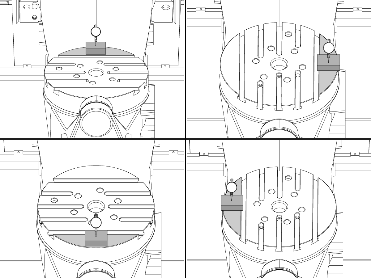
Align the C Axis of rotation perpendicular to the B Axis of rotation:
Remove the bottom C-Axis access cover.
Loosen the (12) bolts [1] that hold the C Axis body to the B Axis platter face.
Reach the bottom (4) bolts through the C Axis access port.
If the B Axis is symmetric in the positive direction [4], install horseshoe shims [2] of appropriate size behind the top (2) bolts.
If the B Axis is symmetric in the negative direction [5], install horseshoe shims [2] of appropriate size behind the bottom (2) bolts.
Torque the (12) bolts to 80 Ft-lbs (108 Nm).
Cut the excessive shim material off.
Verify the measurements in Step 2 after bolts are torqued.


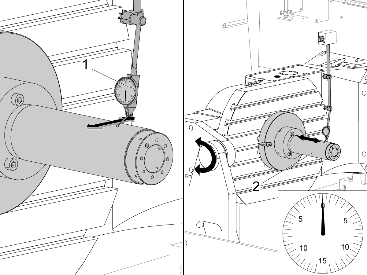
Align the trunnion support shaft co-axial with the B Axis of rotation:
Setup (2) indicators on the outer race of the trunnion support bearing [2] as shown in the picture.
Mark the spot on the outer race where one of the indicator needles is contacting the surface.
After moving the B Axis to 90° or -90° you will align the marked spot with the needle again to exclude the bearing runout error from the measurements.
Take the readings when B is at 90° and B at -90°. Compare the readings.
Caution: The B axis brake needs to be clamped when taking the readings.
The deviation between the results when B is at 90° and at -90° needs to be less than 0.001" on each indicator.
Note: The indicator on the side of the bearing will measure top to bottom alignment and the indicator on the top of the bearing will measure side to side alignment.
____
For models with a multi-piece trunnion
Loosen the (6) bolts [3] on the C Axis body support. Keep the bolts sufficiently snug to control adjustment.
Adjust the (8) set screws [4] until deviation between B at 90° and B at -90° is within 0.001".
Torque the (6) bolts [2] on the C Axis body support to 80 Ft-lbs (108 Nm).
Verify the alignment after the bolts have been torqued.
____
For models with a unibody trunnion
Jog rotary to B90. Set up an indicator on the highlighted surface as shown in the lower diagram .
Rotate B-axis 180 degrees (90 to -90).
Run out (NTE 0.010” TIR).
Caution: If the measurement exceeds the tolerance then contact support.
.png)
Install and shim the A-frame trunnion support:
Move the B Axis to 90°.
Setup an indicator [1] against a machined surface of the C Axis body. Set the indicator to 0.
Use plastic zip ties [2] to pry the seal open while installing the A-frame support. This lets unwanted air and grease out of the assembly.
Install the A-frame trunnion support [3] over the bearings.
Remove the cable ties.
Turn the trunnion support clockwise until it is vertical.
Note: The weight of the A-frame support will cause the trunnion to sag. The amount of sag is measured with the indicator that was previously setup on the side of the C Axis body.
____
For multi-piece trunnions
Adjust the shims [4] between the A-frame support and the base casting to remove the sag until indicator reads 0 again.
When the indicator reading is 0, torque the (4) bolts. Refer to Haas Fastener Torque Specification.
Verify the reading after bolts are torqued. Adjust the shims again if necessary until the indicator reads 0.
____
For models with unibody trunnion
Determine the amount of shim stock [4] needed to raise the Trunnion arm so the indicator reads 0.005".
The indicator [1] value will change once the support is torqued.
With indicator still in place:
Trunnion arm raised (0.005” to 0.010”).
Note: For unibody trunnions, the shim location may also be used to correct the C-axis to X-Y plane perpendicularity instead of shimming the saddle trucks.
Caution: Use equal amount of shims on each side of the A-frame support. Unequal shims will cause the A-frame support to pull the trunnion to the side.
Verify the B Axis of rotation alignment to the Y-Z plane (Step 2). Loosen the bolts and tap the A-frame support side to side if necessary to correct the B axis to Y-Z plane alignment.

Set C-axis perpendicular to X/Y plane:
Move the axes to
UMC-750's........X= -10.5" & Y=0."
UMC-1000's......X=-17.0" & Y=-0."
Zero an indicator [1], on a Ground Block [2], 1/2" off the edge at the rear of the platter (Mag-Base on Spindle), with C at 0 Degrees
Rotate C-Axis to 180°.
Move Y axis, and ground block, in Y Axis negative direction until you are 1/2" away from platter edge, and take the perpendicularity measurement
Adjust the shims until the average error is within 0.0005" end to end.
Note: For unibody trunnions, the shim location under the bearing support may also be used to correct the C-axis to X-Y plane perpendicularity instead of shimming the saddle truck.
Caution: Shim either two front trucks or two rear trucks with the equal shim.
Note: Shim one truck at the time to maintain the X to Y squareness.
Verify the measurements after all bolts are torqued.
Verify the X to Y alignment in Step 2.

Set the tool change offsets:
B-axis tool change offset [1]
For Classic Haas Controls, change Parameter 213.
For Next Generation Controls, go to: Settings>Rotary Tab>Highlight the rotary and press [INSERT], or change Parameter 6.078 (B TOOL CHANGE OFFSET) to set the trunnion (B Axis) parallel to the X Axis.
For models with multipiece trunnion
(NTE 0.001/10"; NTE 0.0020" overall)
For models with unibody trunnion
(NTE 0.0005/10"; NTE 0.0010" overall)
___
C-axis tool change offset [2]
For Classic Haas Controls change Parameter 523.
For Next Generation Control go to: Settings>Rotary Tab> Highlight the rotary and press [INSERT], or change Parameter 7.078 (C TOOL CHANGE OFFSET) to set the table T-slot (C Axis) parallel to the X Axis
For models with multipiece trunnion
(NTE 0.001/10"; NTE 0.0020" overall)
For models with unibody trunnion
(NTE 0.0005/10"; NTE 0.0010" overall)
Check C-axis perpendicularity to X/Y plane:
Align the indicator centered over the C-axis bore with the Y-axis at -10.
Jog positive in the Y-axis and align the indicator over the center of the last section of the platter and make a mark at this spot with a washable marker.
Insert 1-2-3 block as shown and set the indicator to zero.
Remove the block and rotate the platter 90 degrees, following the marked spot with the indicator.
Insert block back between the indicator and platter. Note reading.
Repeat the previous two steps, taking readings with the platter at 180, 270 and 360 degrees.
Multi-piece trunnion: (NTE 0.0005")
Unibody trunnion: (NTE 0.001")
Measure the intersection of the B and C axis:
Follow the linked instruction manual to complete this step.
Align the B-Axis brake disk:
Note: Do not do this step if you are working on a SS machine.
Operate this code in MDI mode to unclamp the brake:
M11;
Loosen all of the brake disc bolts [1] and torque them to 5 Ft-lbs (7 Nm).
Operate this code in MDI mode to clamp the brake:
M10;
Wait 10 seconds.
Torque the bolts. Refer to Haas Fastener Torque Specifications.
设置 参数 1314 用于 CHC / 设置 254 NGC 返回出厂设置的值。(更改值后,将电源循环到机器。
对 WIPS 进行校准和校准。 无线直观探测系统 (WIPS) - 校准
设置机器旋转零点。
填写 完整的检查报告:
将检查报告的副本留在机器中。
如果更换了 B 轴和 C 轴组件,则执行 UMC-750 - B 轴和 C 轴交点 - 对齐
AD0490
版本 A - 2026 年 7 月
X 轴滚动
首先将 T-2192 连接到主轴侧面。
注意:此步骤的 Z 轴位置基于行程顶部,而不是控制器上显示的机床位置。
从行程开始到行程结束点动 X 轴,并记录滚动的任何变化。
B 轴与 Y 轴的平行度
将 C 轴点动到 90°。
测量 Y 轴转盘跳动 (NTE: 0.0008" / 10"; 0.0012" / 15")
然后使用 -90°和 + 90°的 B 轴测量同一表面 (NTE: 0.0008" / 10"; 0.0012" / 15")
说明:进入 -90° 时,注意不要碰到 WIPS 柱和探针。如有必要,拆下 WIPS 以完成此操作。
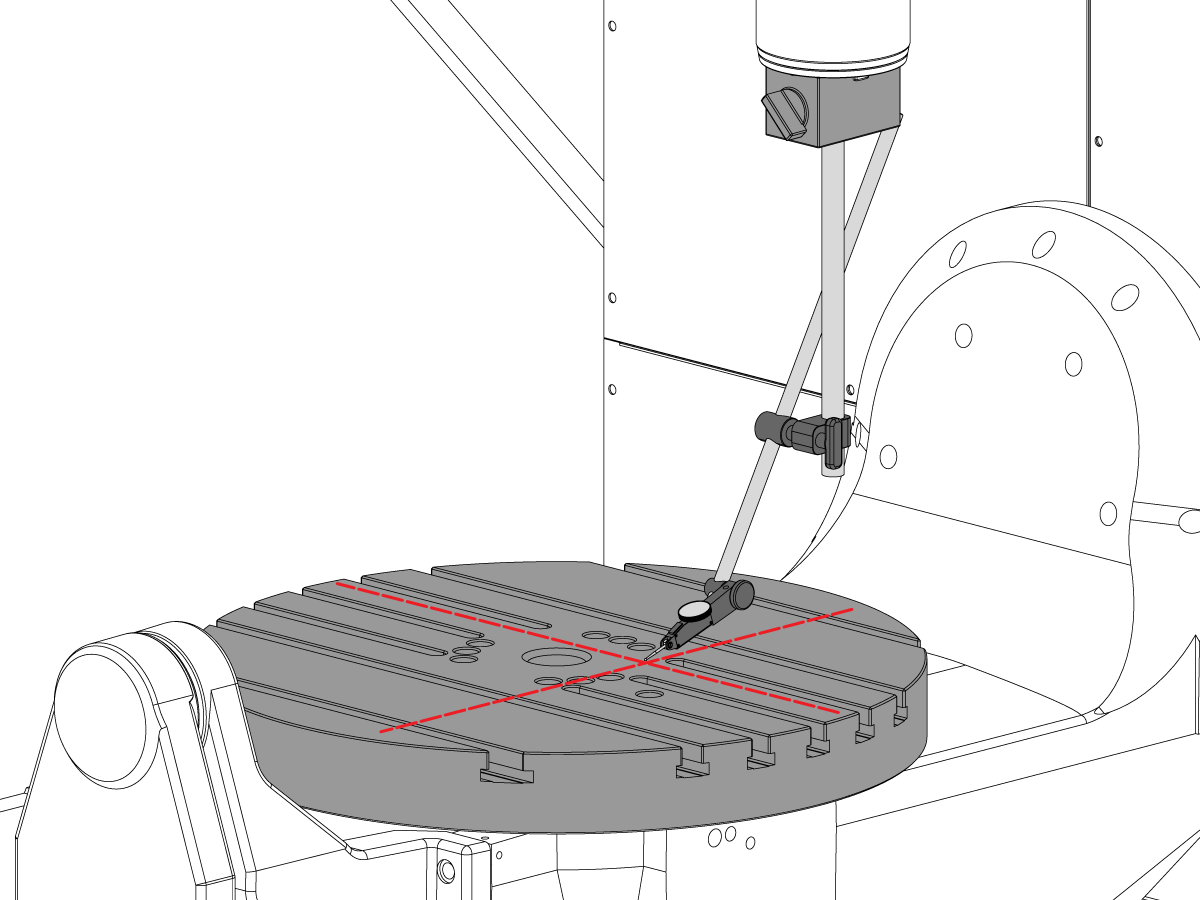
Y 轴与 X 轴的垂直度
使用千斤顶螺杆使花岗岩的顶面平行于 XY 平面 (NTE: 0.0002"/10")
为此步骤将主轴点动到以下位置:
注意:此步骤的 Z 轴位置基于行程顶部,而不是控制器上显示的机床位置。
当轴处于这些位置时,在花岗岩右上角设置指示器。
将花岗岩背面设置为与 X 轴平行(NTE:0.0001"/10)
接下来,检查 Y 轴是否与 X 轴垂直 (NTE 0.0002" / 10")
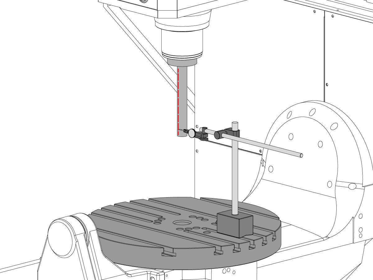
X 轴与 Z 轴的垂直度
将花岗岩和精密圆柱体按所示方向置于转盘上.
为此步骤将主轴点动到以下位置:
注意:此步骤的 Z 轴位置基于行程顶部,而不是控制器上显示的机床位置。
将指示器放在主轴头上,并将指示器的末端对准气缸中心。
使用千斤顶螺杆将圆柱体的顶面设置为与 XY 平面平行 (NTE 0.0002"/10")
将主轴点动回上面列出的位置,并将指示器放在气缸的侧面。点动 Y 轴以找到气缸的高点,并在此位置将指示器归零。
注意: 在查找气缸的高点或将指示器归零时,X/Y 轴的位移不得超出上面列出的值 +/- 0.125"。如有必要,重新调整指示器设置。
沿着气缸向下移动 254 mm,以使 X 轴与 Z 轴垂直 (NTE 0.0005"/10")
Y 轴与 Z 轴的垂直度
将花岗岩和精密圆柱体按所示方向置于转盘上.
为此步骤将主轴点动到以下位置:
注意:此步骤的 Z 轴位置基于行程顶部,而不是控制器上显示的机床位置。
将指示器放在主轴头上,并将指示器的末端对准气缸中心。
使用千斤顶螺杆将圆柱体的顶面设置为与 XY 平面平行 (NTE 0.0002"/10")
将主轴点动回上面列出的位置,并将指示器放在气缸的前部。点动 X 轴以找到气缸的高点,并在该位置将指示器归零。
注意: 在查找气缸的高点或将指示器归零时,X/Y 轴的位移不得超出上面列出的值 +/- 0.125"。如有必要,重新调整指示器设置。
沿着气缸向下移动 254 mm,以使 X 轴与 Z 轴垂直 (NTE 0.0005"/10")
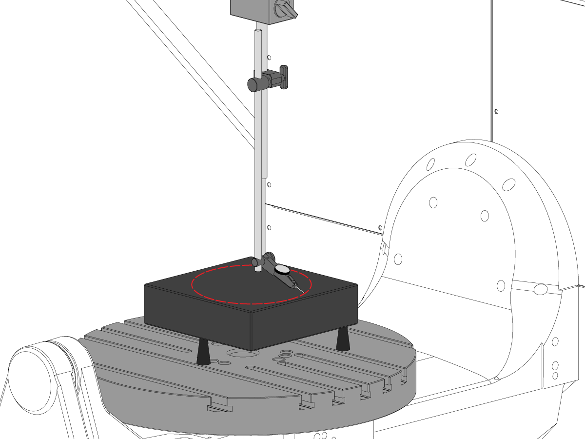
C 轴与 XY 平面的垂直度
将精密量规滑块置于 12 点钟方向的转盘边缘。
将 C 轴旋转至 90°
12 点钟与 6 点钟位置间的测量差值决定了整个 X 轴的平整度(NTE 0.0005")
3 点钟与 9 点钟位置间的测量差值决定了整个 Y 轴的平整度(NTE 0.0005")
转盘面跳动
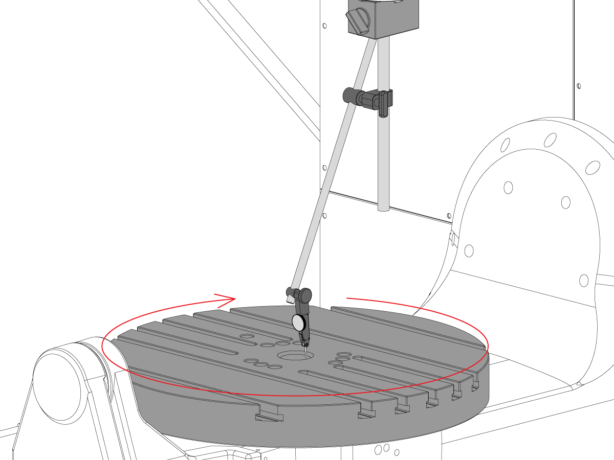
将精密量规滑块置于 12 点钟方向的转盘边缘。
旋转C轴 90°,但将量规滑块保持在 12 点钟位置
注意:此步骤 C 轴制动器关闭
转盘表面与 XY 平面的平行度
主轴跳动
检查测试棒料底座的主轴跳动(NTE 0.0005" TIR)
检查测试棒料底座以下的主轴跳动 6" (NTE 0.001" TIR)
主轴中心线与 Z 轴的平行度
将主轴中心对准 C 轴转盘孔。扫过 10" 直径圆。
记录 XZ TIR (NTE 0.0005")
记录 YZ TIR (NTE 0.0005")
C 轴孔的同轴度
拆下转盘的中心插头。
如图所示放置指示器并点动 C 轴 360°。
机床转台零点
TG0151

在对 UMC-750 精度或几何问题进行故障排除之前,技术人员必须彻底了解以下基本原理:
需要系统化、按正确的顺序解决 UMC-750 机器几何形状或精度问题。应严格遵守以下信息,并按顺序遵循。
在对机器几何体进行任何评估或调整之前,必须检查机器是否正确水平,并将旋转轴对准机器,这一点绝对至关重要。
许多错误可以归因于机器崩溃或工具应用或编程问题的问题。在未根据检验报告彻底检查机床整体水平和几何形状的情况下,不要试图更改机床几何形状。这包括检查 Machine Rotary Zero Point (MRZP).
发生碰撞时,机器上有 4 个滑点。这些区域是主轴头到柱塞、柱塞到鞍座、鞍座到龙门、耳轴到耳轴支架。
注意:这些接头都不应安装垫片。机床崩溃不应更改出厂设置中所需的垫片数量。
请务必记住机器的线性精度为 0.0004/10" 角精度为 +/- 15 arc. sec. 这些公差可以迅速增加。
应竭尽全力确定加工应用是否合理,并在机床、固定和刀具能力范围内。
确定以前是否计算机崩溃。查看报警历史记录;查找钣金、工作台、主轴头等的物理损坏。无论如何 "小" 撞车,会影响机器的几何形状。如果机器被撞毁,需要对机器几何形状进行全面检查
评估零件固定的整体状况和切削刀具的状况。
获取完整的计算机备份和错误报告。
验证机器是否水平,旋转轴与机器对齐
注意: 此时,除了调整水平支脚外,不要尝试对机器几何体进行任何调整。
如果机器出水平或旋转未对齐,则重置电平和旋转对齐。
执行完整的几何检查,记录每个轴的任何误差的幅度和方向。
分析检查报告。
如果检查报告的任何部分不容差,则需要重新对齐机器。
收集有关零件、工件和工具的以下信息:
TG0150

若要获取 UMC 应用故障排除指南:
按照此链接 文档和软件 | HBC
或者
注意:仅 Haas 认证的服务技术人员才能登录此站点。
选择 Service(维修)选项卡。
在 Utilities(实用程序)下方,选择 Documents and Software(文档和软件)。
选择 Applications(应用)文件夹。
AD0131
这是以下套件的“垫片套件清单”:
| 厚度 | 部分# | 套件中的数量 | 已使用 |
| .02100 | 20-9358A | 2 | |
| 0.2105 | 20-9359A | 2 | |
| .02110 | 20-9383A | 2 | |
| 0.2115 | 20-9365A | 2 | |
| 0.2120 | 20-9384A | 2 | |
| 0.2125 | 20-9385A | 2 | |
| 0.2130 | 20-9368A | 2 | |
| 0.2135 | 20-9369A | 2 | |
| 0.2140 | 20-9386A | 2 | |
| 0.2145 | 20-9371A | 2 | |
| 0.2150 | 20-9372A | 2 | |
| 0.2155 | 20-9387A | 2 | |
| 0.2160 | 20-9374A | 2 | |
| 0.2165 | 20-9375A | 2 | |
| 0.2170 | 20-9376A | 2 | |
| 0.2175 | 20-9377A | 2 | |
| 0.2180 | 20-9378A | 2 | |
| 0.2185 | 20-9379A | 2 | |
| 0.2190 | 20-9380A | 2 | |
| 0.2195 | 20-9381A | 2 | |
| 0.2200 | 20-9382A | 2 |
注意: 仅限套件所有者:订购替换件时,请指定垫片厚度。例如,20-9382 0.2145
| 厚度 | 部分# | 套件中的数量 | 已使用 |
| 0.0010 | 59-0240 | 2 | |
| 0.0020 | 59-0241 | 2 | |
| 0.0030 | 59-0242 | 2 |
| 厚度 | 部分# | 套件中的数量 | 已使用 |
| 0.2130 | 20-6282A | 2 | |
| 0.2135 | 20-6283A | 2 | |
| 0.2140 | 20-6284A | 2 | |
| 0.2145 | 20-6285A | 2 | |
| 0.2150 | 20-6286A | 2 | |
| 0.2155 | 20-6287A | 2 | |
| 0.2160 | 20-6288A | 2 | |
| 0.2165 | 20-6289A | 2 | |
| 0.2170 | 20-6290A |
2 | |
| 0.2175 | 20-6291A | 2 | |
| 0.2180 | 20-6294A | 2 | |
| 0.2185 | 20-6295A | 2 | |
| 0.2190 | 20-6292A | 2 | |
| 0.2195 | 20-6293A | 2 | |
| 0.2200 | 20-6296A | 2 | |
| 0.2205 | 20-6297A | 2 | |
| 0.2210 | 20-6277A | 2 | |
| 0.2215 | 20-6279A | 2 | |
| 0.2220 | 20-6278A | 2 | |
| 0.2225 | 20-6298A | 2 | |
| 0.2230 | 20-6281A | 2 |
注意: 仅限套件所有者:订购替换件时,请指定垫片厚度。例如,20-6290A 0.2080
在使用的列中记录从套件中拆下的垫片。
将检查表连同垫片套件一起返回。
将原垫片放回箱中返回。

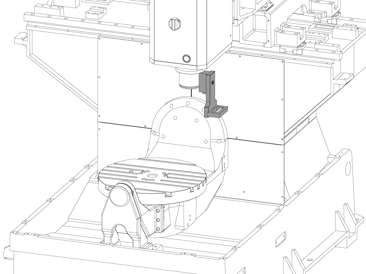
此过程演示如何测量和对齐 B 轴和 C 轴的交集。 在尝试此过程之前,请验证机器是否按 UMC-750 水平.
您需要在以下任一情况后对齐 B 轴和 C 轴:
5 轴旋转中心距离定义旋转中心之间的差异: C 轴机器旋翼零点 (MRZP) 和 X 轴中的 B 轴 MRZP。
C 轴和 B 轴 MRZP 之间可能无区别。
您将需要以下工具:
How to identify the Multi-Piece and the Unibody trunnion
1) Multi-Piece trunnion: UMC machines built approximetely before 11/2022 will have this configuration.
2) Unibody trunnion: UMC machines built approximetely after 11/2022 will have this configuration.
Remove the A-frame trunnion support:
Remove the bolts [1] that secure the A-frame trunnion support [2] to the base and take out the shims between A-frame support and the base.
Rotate the A-frame support [2] counter-clockwise to clear the edge of the base [3].
Pull the A-frame support off the bearings.
Note: The A-frame support might vacuum lock on the bearings. Use the zip-tie to pry the seal [4] open.
Caution: To lift the trunnion support, get the aid of another person. The support weighs 85 lbs (39 kg).
Measure the B- axis of rotation parallelism to the Y-Z plane:
For a machine with a Classic Haas Control, change Parameter 151:20 (B axis CHK TRAVL LIM) to 0.
For a machine with a Next Generation Control, change Parameter 6.021 (B axis CHK TRAVL LIM) to FALSE.
Measure the parallelism of the platter to the Y-Z plane with the B axis at 90° and then the B axis at -90° as shown in the picture.
Position the Y-Axis in the following starting position:
UMC-500: Y=0, Sweep 15”, 3rd T-Slot Land from the top.
UMC-750/1500-Duo: Y=-1.0, Sweep 18", 3rd T-Slot Land from the Top .
UMC-1250: Y=-1.0, Sweep 28", 3rd T-Slot Land from the Top.
UMC-500PP: Y=-4.0, Sweep 7".
UMC-750PP: Y=-2”, Sweep 15".
UMC-1000PP: Y=-4”, Sweep 15".
Compare the results at B 90° and B-90°. The results should be...
If the results are symmetric against Y-Z plane, and are less than 0.0010"/20 inches: Go to Step 5.
If the results are symmetric against Y-Z plane, but are more than 0.0010"/20 inches: Go to Step 4.
Warning: If the results [3] are not symmetric against the Y-Z plane, the B axis rotary needs to be aligned: Go to Step 3.
Align the B axis of rotation parallel to the Y-Z plane:
Loosen the (6) bolts [1] that secure the B axis rotary to the base casting.
Note: Keep the bolts sufficiently snug to control the adjustments.
Adjust the front and rear setscrews [2] until the measurements taken in Step 2 are symmetric against the Y-Z plane.
Torque the (6) bolts [1]. Refer to Haas Fastener Torque Specification.
Verify the measurements in Step 2 after the bolts have been torqued.
Align the C Axis of rotation perpendicular to the B Axis of rotation:
Remove the bottom C-Axis access cover.
Loosen the (12) bolts [1] that hold the C Axis body to the B Axis platter face.
Reach the bottom (4) bolts through the C Axis access port.
If the B Axis is symmetric in the positive direction [4], install horseshoe shims [2] of appropriate size behind the top (2) bolts.
If the B Axis is symmetric in the negative direction [5], install horseshoe shims [2] of appropriate size behind the bottom (2) bolts.
Torque the (12) bolts to 80 Ft-lbs (108 Nm).
Cut the excessive shim material off.
Verify the measurements in Step 2 after bolts are torqued.
Align the trunnion support shaft co-axial with the B Axis of rotation:
Setup (2) indicators on the outer race of the trunnion support bearing [2] as shown in the picture.
Mark the spot on the outer race where one of the indicator needles is contacting the surface.
After moving the B Axis to 90° or -90° you will align the marked spot with the needle again to exclude the bearing runout error from the measurements.
Take the readings when B is at 90° and B at -90°. Compare the readings.
Caution: The B axis brake needs to be clamped when taking the readings.
The deviation between the results when B is at 90° and at -90° needs to be less than 0.001" on each indicator.
Note: The indicator on the side of the bearing will measure top to bottom alignment and the indicator on the top of the bearing will measure side to side alignment.
____
For models with a multi-piece trunnion
Loosen the (6) bolts [3] on the C Axis body support. Keep the bolts sufficiently snug to control adjustment.
Adjust the (8) set screws [4] until deviation between B at 90° and B at -90° is within 0.001".
Torque the (6) bolts [2] on the C Axis body support to 80 Ft-lbs (108 Nm).
Verify the alignment after the bolts have been torqued.
____
For models with a unibody trunnion
Jog rotary to B90. Set up an indicator on the highlighted surface as shown in the lower diagram .
Rotate B-axis 180 degrees (90 to -90).
Run out (NTE 0.010” TIR).
Caution: If the measurement exceeds the tolerance then contact support.
Install and shim the A-frame trunnion support:
Move the B Axis to 90°.
Setup an indicator [1] against a machined surface of the C Axis body. Set the indicator to 0.
Use plastic zip ties [2] to pry the seal open while installing the A-frame support. This lets unwanted air and grease out of the assembly.
Install the A-frame trunnion support [3] over the bearings.
Remove the cable ties.
Turn the trunnion support clockwise until it is vertical.
Note: The weight of the A-frame support will cause the trunnion to sag. The amount of sag is measured with the indicator that was previously setup on the side of the C Axis body.
____
For multi-piece trunnions
Adjust the shims [4] between the A-frame support and the base casting to remove the sag until indicator reads 0 again.
When the indicator reading is 0, torque the (4) bolts. Refer to Haas Fastener Torque Specification.
Verify the reading after bolts are torqued. Adjust the shims again if necessary until the indicator reads 0.
____
For models with unibody trunnion
Determine the amount of shim stock [4] needed to raise the Trunnion arm so the indicator reads 0.005".
The indicator [1] value will change once the support is torqued.
With indicator still in place:
Trunnion arm raised (0.005” to 0.010”).
Note: For unibody trunnions, the shim location may also be used to correct the C-axis to X-Y plane perpendicularity instead of shimming the saddle trucks.
Caution: Use equal amount of shims on each side of the A-frame support. Unequal shims will cause the A-frame support to pull the trunnion to the side.
Verify the B Axis of rotation alignment to the Y-Z plane (Step 2). Loosen the bolts and tap the A-frame support side to side if necessary to correct the B axis to Y-Z plane alignment.
Set C-axis perpendicular to X/Y plane:
Move the axes to
UMC-750's........X= -10.5" & Y=0."
UMC-1000's......X=-17.0" & Y=-0."
Zero an indicator [1], on a Ground Block [2], 1/2" off the edge at the rear of the platter (Mag-Base on Spindle), with C at 0 Degrees
Rotate C-Axis to 180°.
Move Y axis, and ground block, in Y Axis negative direction until you are 1/2" away from platter edge, and take the perpendicularity measurement
Adjust the shims until the average error is within 0.0005" end to end.
Note: For unibody trunnions, the shim location under the bearing support may also be used to correct the C-axis to X-Y plane perpendicularity instead of shimming the saddle truck.
Caution: Shim either two front trucks or two rear trucks with the equal shim.
Note: Shim one truck at the time to maintain the X to Y squareness.
Verify the measurements after all bolts are torqued.
Verify the X to Y alignment in Step 2.
Set the tool change offsets:
B-axis tool change offset [1]
For Classic Haas Controls, change Parameter 213.
For Next Generation Controls, go to: Settings>Rotary Tab>Highlight the rotary and press [INSERT], or change Parameter 6.078 (B TOOL CHANGE OFFSET) to set the trunnion (B Axis) parallel to the X Axis.
For models with multipiece trunnion
(NTE 0.001/10"; NTE 0.0020" overall)
For models with unibody trunnion
(NTE 0.0005/10"; NTE 0.0010" overall)
___
C-axis tool change offset [2]
For Classic Haas Controls change Parameter 523.
For Next Generation Control go to: Settings>Rotary Tab> Highlight the rotary and press [INSERT], or change Parameter 7.078 (C TOOL CHANGE OFFSET) to set the table T-slot (C Axis) parallel to the X Axis
For models with multipiece trunnion
(NTE 0.001/10"; NTE 0.0020" overall)
For models with unibody trunnion
(NTE 0.0005/10"; NTE 0.0010" overall)
Check C-axis perpendicularity to X/Y plane:
Align the indicator centered over the C-axis bore with the Y-axis at -10.
Jog positive in the Y-axis and align the indicator over the center of the last section of the platter and make a mark at this spot with a washable marker.
Insert 1-2-3 block as shown and set the indicator to zero.
Remove the block and rotate the platter 90 degrees, following the marked spot with the indicator.
Insert block back between the indicator and platter. Note reading.
Repeat the previous two steps, taking readings with the platter at 180, 270 and 360 degrees.
Multi-piece trunnion: (NTE 0.0005")
Unibody trunnion: (NTE 0.001")
Measure the intersection of the B and C axis:
Follow the linked instruction manual to complete this step.
Align the B-Axis brake disk:
Note: Do not do this step if you are working on a SS machine.
Operate this code in MDI mode to unclamp the brake:
M11;
Loosen all of the brake disc bolts [1] and torque them to 5 Ft-lbs (7 Nm).
Operate this code in MDI mode to clamp the brake:
M10;
Wait 10 seconds.
Torque the bolts. Refer to Haas Fastener Torque Specifications.

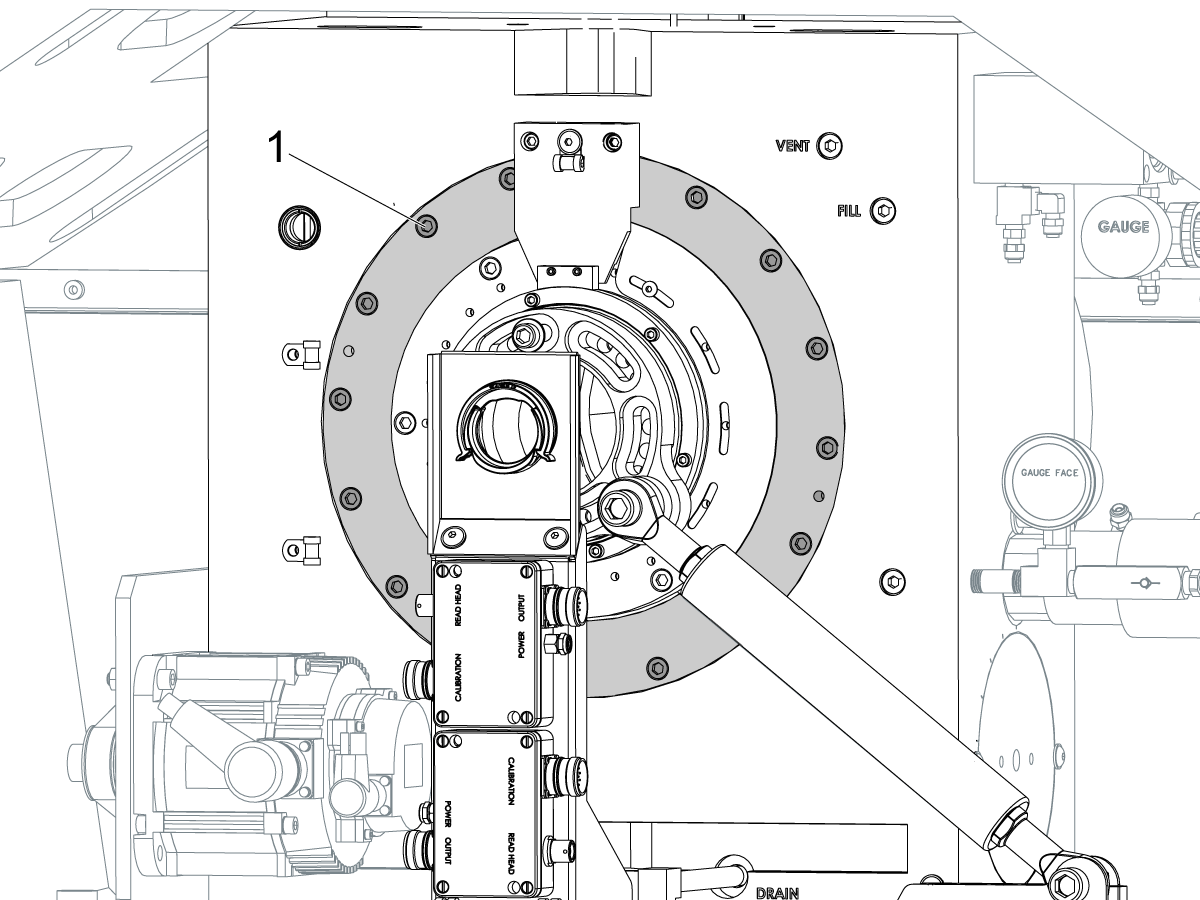
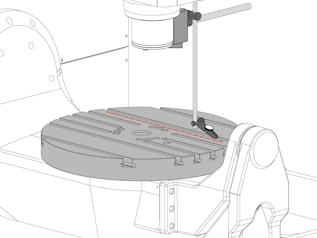
Install the B Axis and C Axis intersection tool:
Jog the C Axis to 0°.
Push [EMERGENCY STOP].
Clean the table.
Guide the shaft of the adapter [1] while you slowly lower it into the center bore.
Attach the adapter to the table with (2) screws [4] and (2) T-nuts.
Attach the alignment bar [2] to the adapter with (3) screws [3].
Snug the (3) screws to allow for adjustments in the next step.

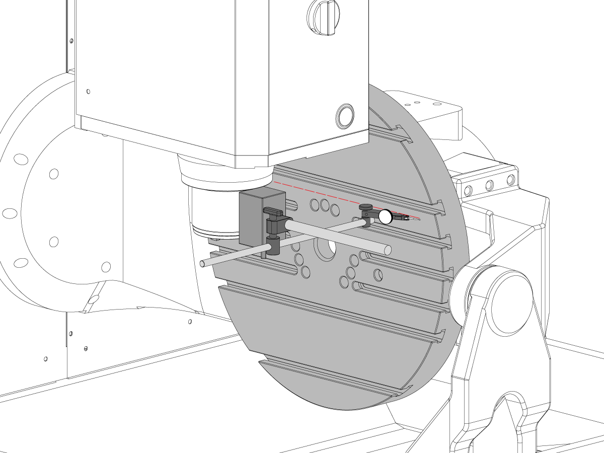
Align the B/C intersection tool with the C Axis:
Put an indicator on the front side of the alignment bar near the base.
Release the [EMERGENCY STOP]. Push [RESET] to clear any alarms.
Jog across the tool in the X Axis to find the high spot.
Set the indicator to 0.
Jog the C Axis 360°.
Lightly tap the base with a rubber mallet to adjust the radial error on the alignment bar.
Note: Adjust the alignment bar to half of the measured error, because you are measuring the diameter error.
Jog the C Axis 360°.
When correctly adjusted the radial error is less than 0.0002" (0.005 mm).
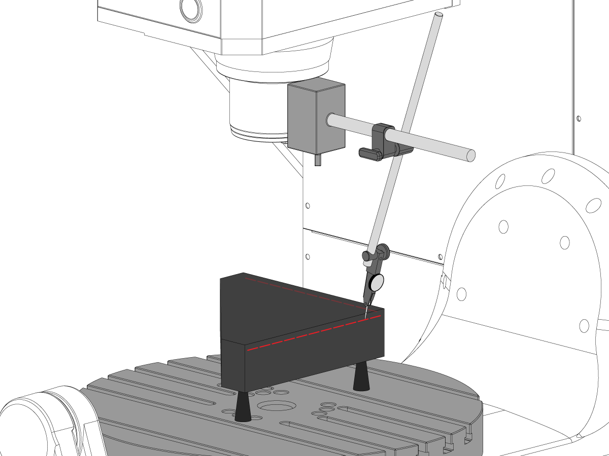
Check the B/C intersection:
Center the indicator [1] on the front side of the alignment bar near the top of the cylinder.
Jog across the tool in the X Axis to find the high spot.
Zero the indicator.
Jog the C Axis 360°.
Turn the (3) screws [2] on the alignment bar to adjust the runout.
Jog the C Axis 360°.
When correctly adjusted the radial error is less than 0.0002" (0.005 mm).
Repeat Step 2 and verify the alignment did not change.

For a machine with a Classic Haas Control change:
For a machine with a Next Generation Control change:
Push [ZERO RETURN]. Then push [ALL].
Jog the B-axis to -90°.
Note: The rotary positions are for reference only.
Put an indicator [1] on top of the alignment bar.
Jog in the Y-axis to find the high point.
Set the indicator to 0.
Jog across the alignment bar in the X-axis [2].
Jog the B-axis to adjust the alignment bar parallel to the X plane.
Set the indicator to 0.
Jog the Y-axis to 0.
Caution: Make sure the indicator assembly is clear of the B-axis movement.
Caution: Do not move the Z-axis.

Jog the B-axis to +90°.
Caution: Make sure the indicator assembly is clear of the B-axis movement.
Jog the Y-axis [1] to find the high point on the alignment bar.
Note: Do not set the indicator to 0.
Jog across the alignment bar in the X-axis.
Jog the B-axis to adjust the alignment bar parallel [2] to the X plane.
When the alignment bar is parallel to the X plane, the indicator reading is the change needed in the Z-Axis (∆Z=indicator reading).
Record the value shown on the indicator. In this example the indicator now shows 0.0015". ∆Z is 0.0015".
Do these calculations to get the value for CHC Parameter 1314 or NGC Setting 254. (In this example the difference in readings for the B-C intersection (∆Z) is 0.0015".):
Set Parameter CHC Parameter 1314 (Rotary Axes Center Deviation in X) or NGC Setting 254 (5-Axis Rotary Center Distance), to the calculated value.
In this example, set parameter CHC Parameter 1314 to 7 or NGC Setting 254 to 0.0007.
Cycle the power to save CHC Parameter 1314 or NGC Setting 254.
Repeat Steps 1-3 to verify that the value for ∆Z is less than 0.0002" (0.005 mm).
Jog the B-Axis to the home position.
Set Parameter 151:20 (B-Axis CK Travel Limit) to 1.
Make sure the MRZP offsets are correct.
Calibrate WIPS per Wireless Intuitive Probe System (WIPS) - Calibration.
Complete an inspection report. Refer to UMC-750 Inspection Report.
Recently Viewed Items
You Have No Recently Viewed Items Yet

此价格包含运费、出口和进口关税、保险费以及任何在运送至与您(买家)商定的位于法国的某一地点的过程中产生的其他费用。在 Haas 数控产品的交付中不会添加任何其他强制性费用。
随时掌握 HAAS 最新提示和技术……
HAAS TOOLING 接受以下条件:


This site is protected by reCAPTCHA and the Google Privacy Policy and Terms of Service apply.

2800 Sturgis Rd., Oxnard, CA 93030 / Toll Free: 800-331-6746
Phone: 805-278-1800 / Fax: 805-278-2255


