-
stroji
-
Vertikalni rezkarji
Vertikalni rezkarji
-
Večosne rešitve
Večosne rešitve
-
Stružnice
Stružnice
-
Horizontalni rezkarji
Horizontalni rezkarji
-
Rotacijske mize in indekserji
Rotacijske mize in indekserji
-
Avtomatizirani sistemi
Avtomatizirani sistemi
-
Namizni stroji
Namizni stroji
-
Oprema za delavnice
Oprema za delavnice
-
Stroji za proizvodnjo
Stroji za proizvodnjo
ORODJA ZA NAKUPOVANJESE ŽELITE S KOM POGOVORITI?Tovarniška izpostava Haas (HFO) lahko odgovori na vaša vprašanja in vam predstavi vaše najboljše možnosti.
CONTACT YOUR DISTRIBUTOR > -
Vertikalni rezkarji
-
Možnosti
-
/2026-04-VOP-SquareComponent.jpg/_jcr_content/renditions/cq5dam.thumbnail.319.319.png) Paketi možne vrednosti
Paketi možne vrednosti
Paketi možne vrednosti
Paketi možne vrednosti -
 Vretena
Vretena
Vretena -
 Menjalci orodja
Menjalci orodja
Menjalci orodja -
 4. | 5. os
4. | 5. os
4. | 5. os -
 Revolverji in gnana orodja
Revolverji in gnana orodja
Revolverji in gnana orodja -
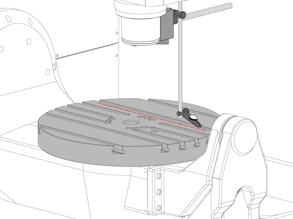
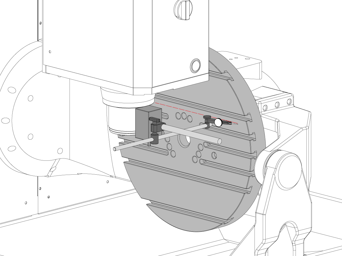
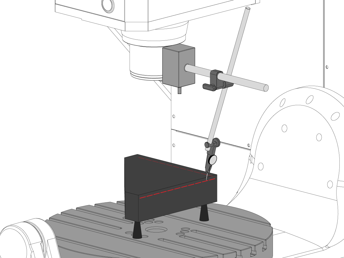
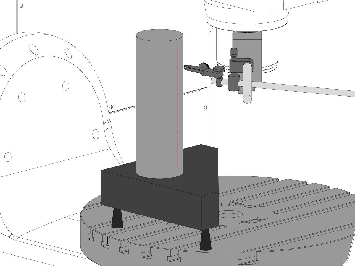
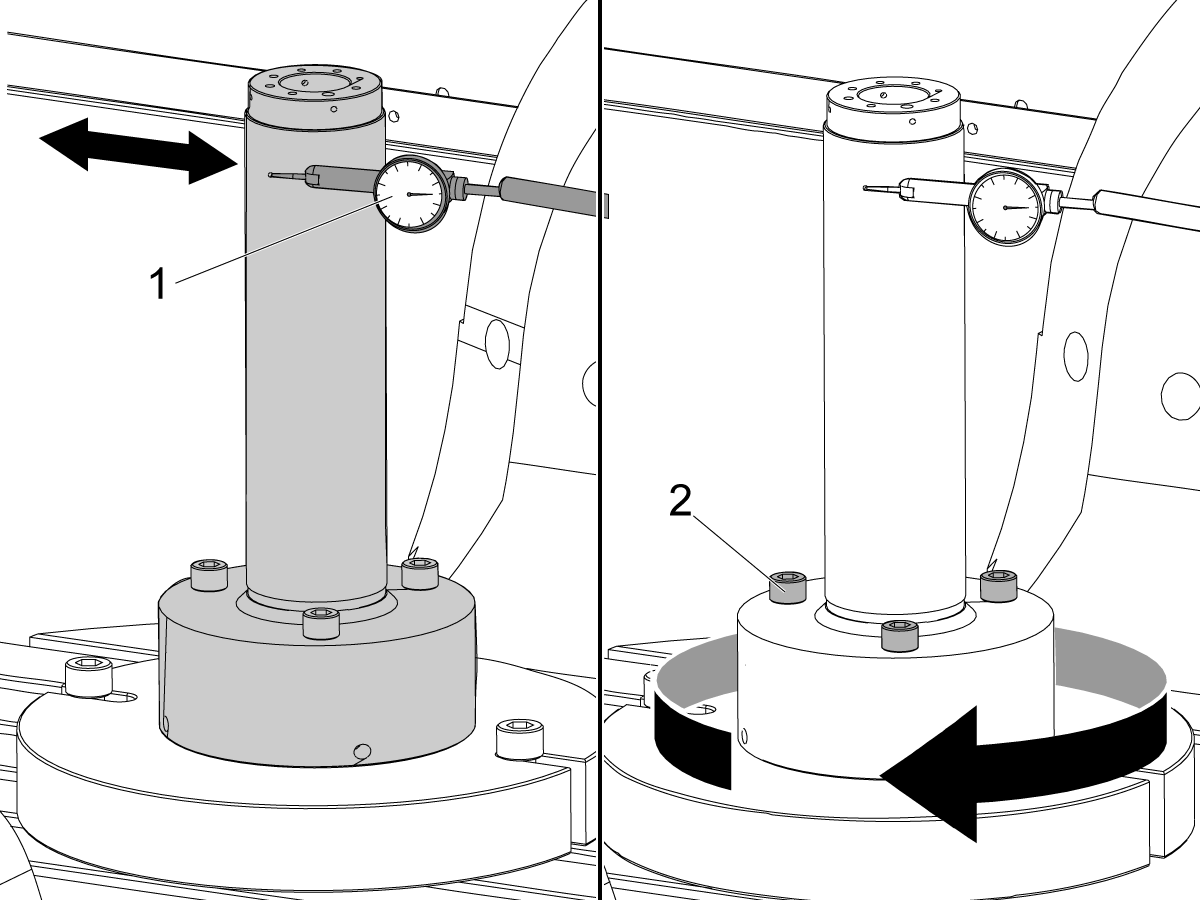
 Merjenje s sondo
Merjenje s sondo
Merjenje s sondo -
 Obvladovanje odrezkov in emulzije
Obvladovanje odrezkov in emulzije
Obvladovanje odrezkov in emulzije -
 Krmilje Haas
Krmilje Haas
Krmilje Haas -
 Opcije izdelka
Opcije izdelka
Opcije izdelka -
 Orodje in vpenjanje
Orodje in vpenjanje
Orodje in vpenjanje -
 Vpenjanje obdelovanca
Vpenjanje obdelovanca
Vpenjanje obdelovanca -
 5-osne rešitve
5-osne rešitve
5-osne rešitve -
 Avtomatizacija
Avtomatizacija
Avtomatizacija
ORODJA ZA NAKUPOVANJESE ŽELITE S KOM POGOVORITI?Tovarniška izpostava Haas (HFO) lahko odgovori na vaša vprašanja in vam predstavi vaše najboljše možnosti.
CONTACT YOUR DISTRIBUTOR > -
-
Why Haas
Spoznajte Haasovo razliko
-
Servis
- Videoposnetki


.png)