-
機械
-
立型マシニングセンター
立型マシニングセンター
-
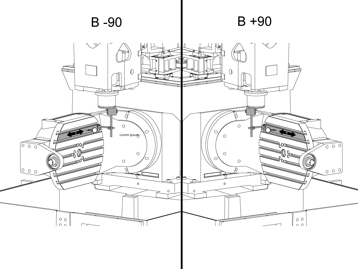
多軸制御ソリューション
多軸制御ソリューション
-
旋盤
旋盤
-
横型マシニングセンター
横型マシニングセンター
-
ロータリーとインデクサ
ロータリーとインデクサ
-
オートメーション システム
オートメーション システム
-
デスクトップ機械
デスクトップ機械
-
工場機器
工場機器
-
製造機械
製造機械
ショッピングツール -
立型マシニングセンター
- オプション
-
Why Haas
Haasの特徴を見る
-
サービス
Haas Service へようこそ
- ビデオ
-
ショッピングツール
-


.png)