-
strojevi
-
Vertikalne glodalice
Vertikalne glodalice
-
Višeosna rješenja
Višeosna rješenja
-
Tokarilica
Tokarilica
-
Horizontalne glodalice
Horizontalne glodalice
-
rotacioni proizvodi i indekseri
rotacioni proizvodi i indekseri
-
Sustavi automatizacije
Sustavi automatizacije
-
Desktop strojevi
Desktop strojevi
-
Oprema za radionice
Oprema za radionice
-
Strojevi za izradu
Strojevi za izradu
ŽELITE RAZGOVARATI S NEKIM?Haas tvornički dućan (outlet) (HFO) može odgovoriti na vaša pitanja i provesti vas kroz najbolje opcije.
CONTACT YOUR DISTRIBUTOR > -
Vertikalne glodalice
-
Opcije
-
/2026-04-VOP-SquareComponent.jpg/_jcr_content/renditions/cq5dam.thumbnail.319.319.png) Paketi vrijednosnih opcija
Paketi vrijednosnih opcija
Paketi vrijednosnih opcija
Paketi vrijednosnih opcija -
 Glavna vretena
Glavna vretena
Glavna vretena -
 Izmjenjivači alata
Izmjenjivači alata
Izmjenjivači alata -
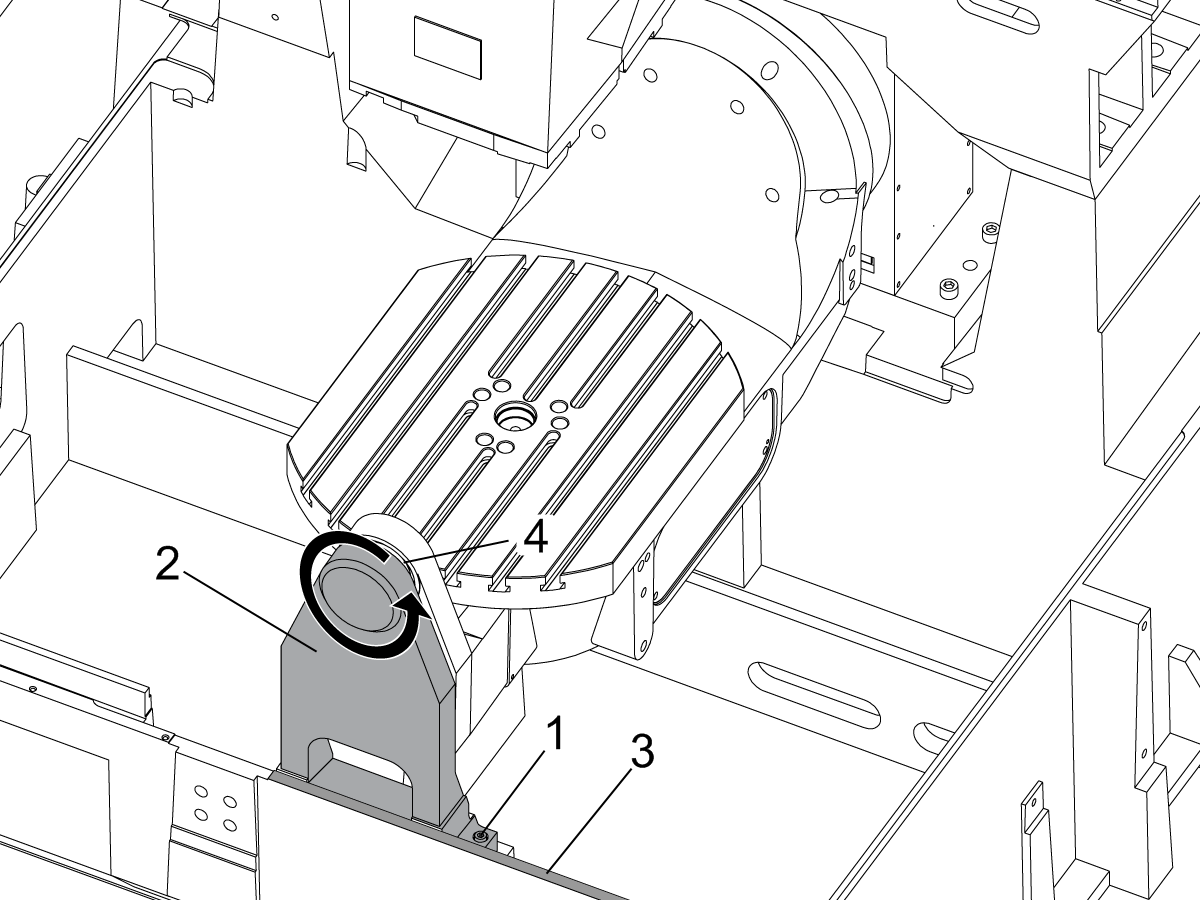
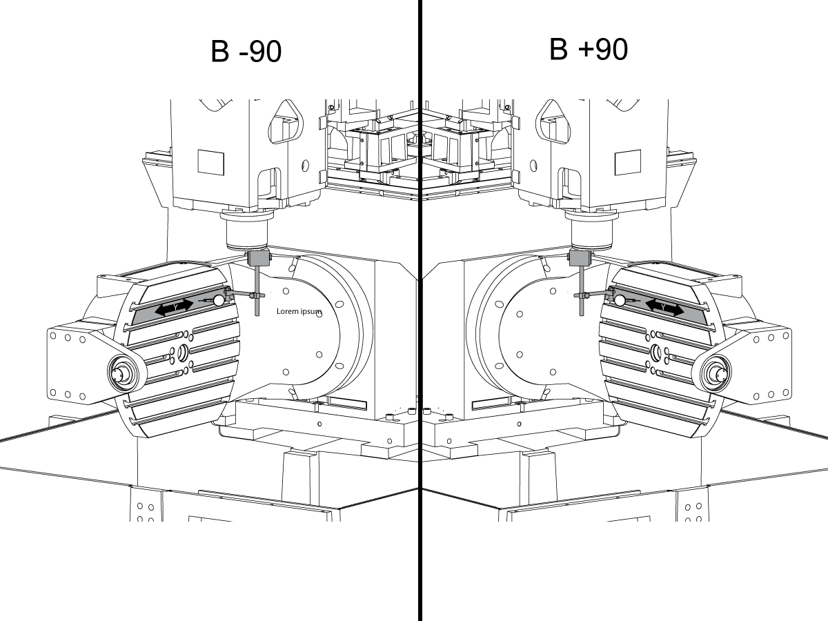
 4- | 5-osni
4- | 5-osni
4- | 5-osni -
 Revolveri i pogonjeni alati
Revolveri i pogonjeni alati
Revolveri i pogonjeni alati -
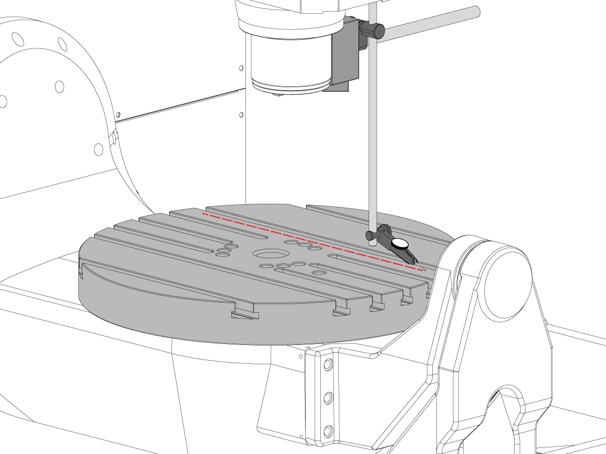
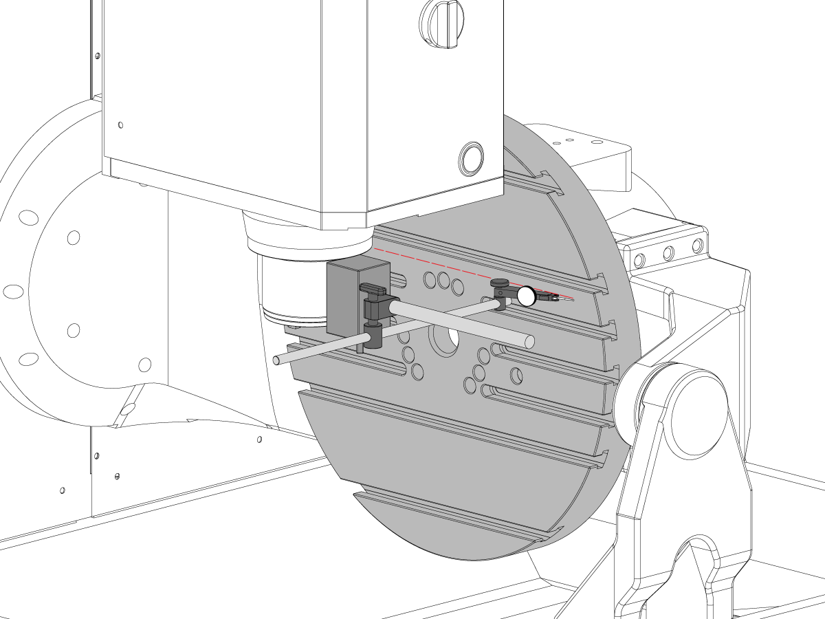
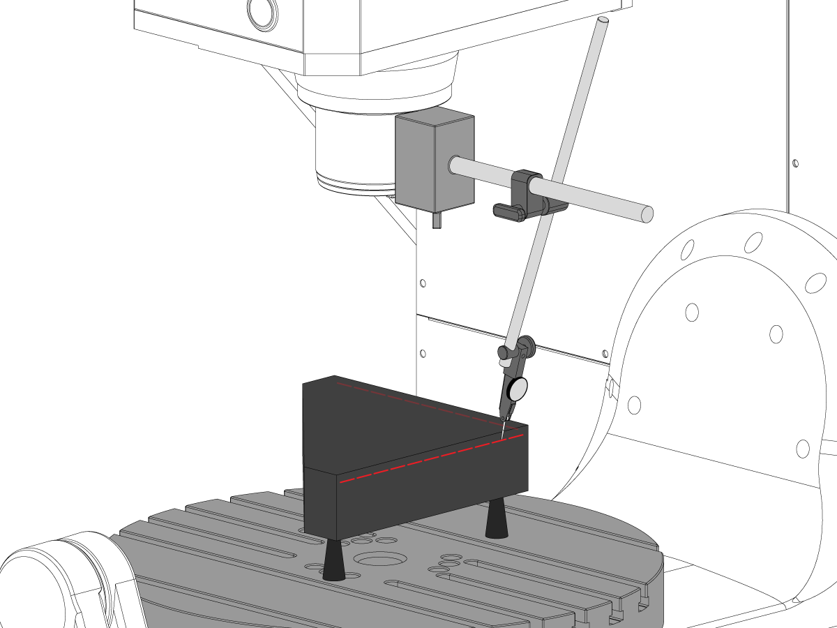
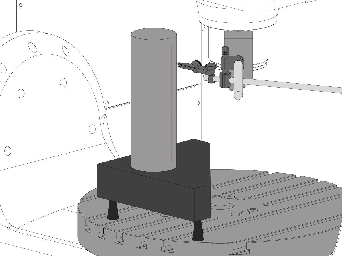
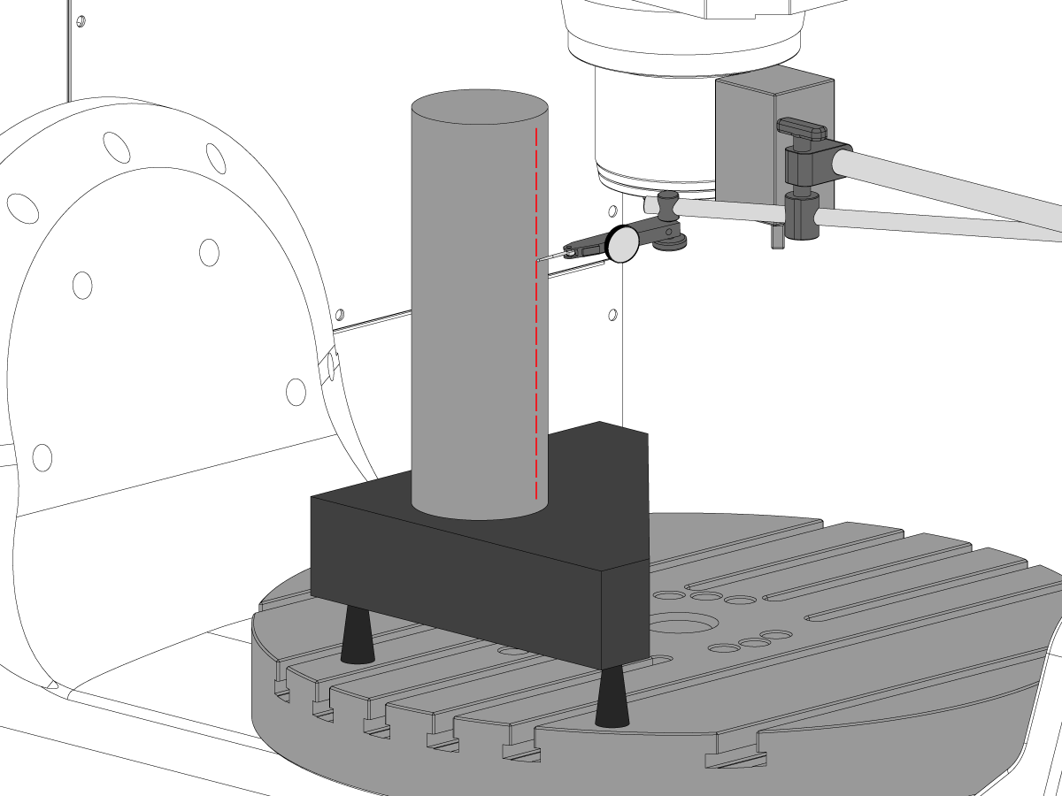
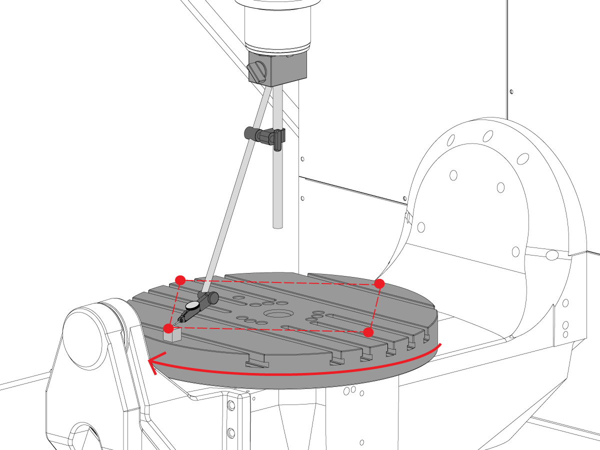
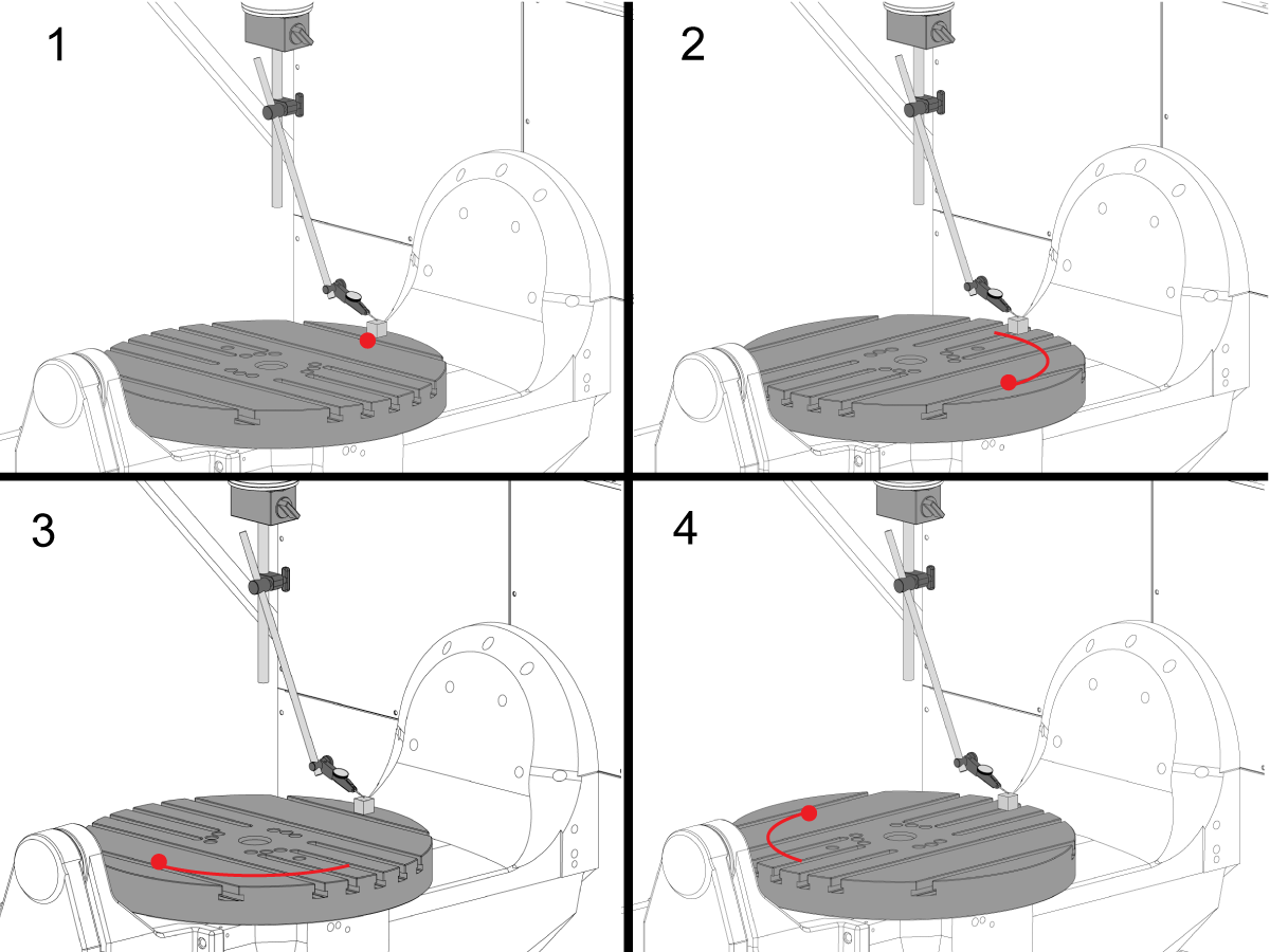
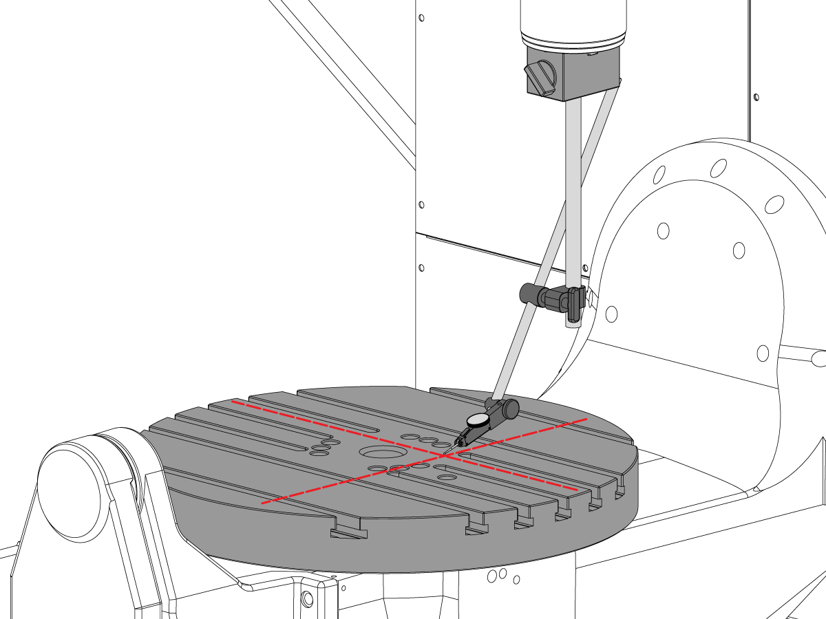
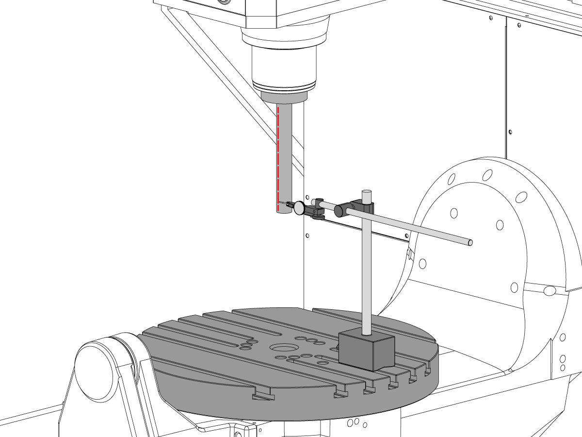
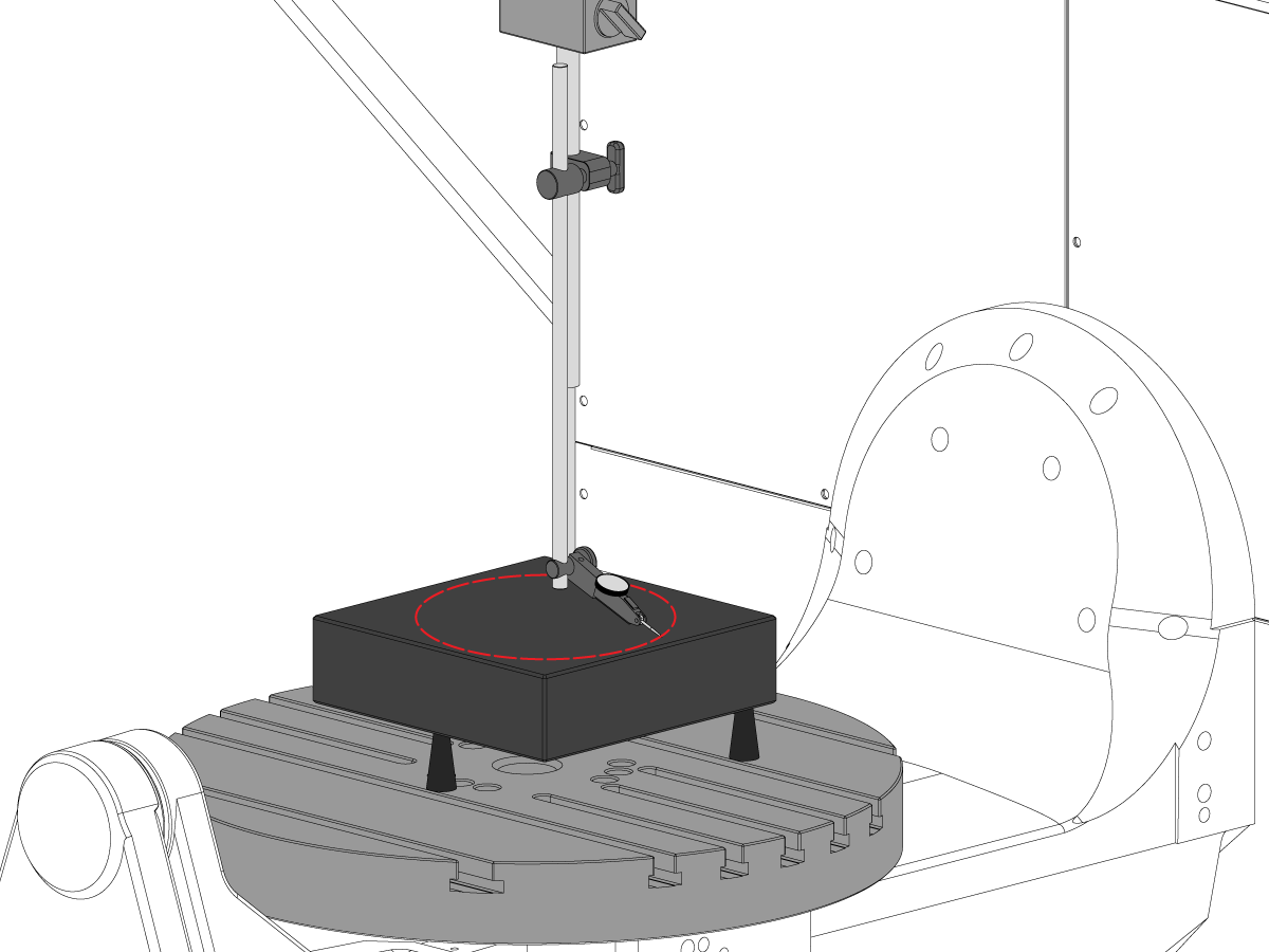
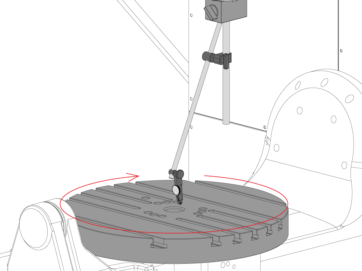
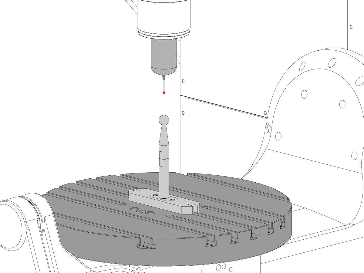
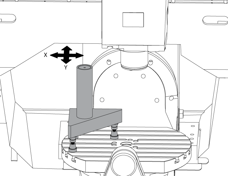
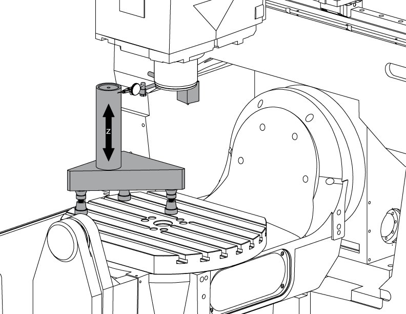
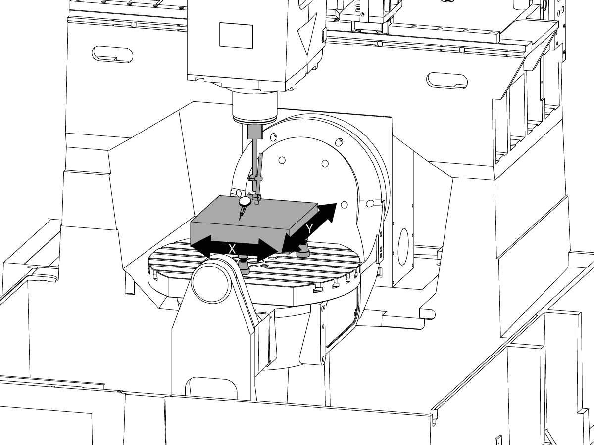
 Sondiranje
Sondiranje
Sondiranje -
 Upravljanje strugotinom i rashladnim sredstvima
Upravljanje strugotinom i rashladnim sredstvima
Upravljanje strugotinom i rashladnim sredstvima -
 Haas upravljačka naprava
Haas upravljačka naprava
Haas upravljačka naprava -
 Opcije proizvoda
Opcije proizvoda
Opcije proizvoda -
 Alati i Stezanje i prihvat sirovca
Alati i Stezanje i prihvat sirovca
Alati i Stezanje i prihvat sirovca -
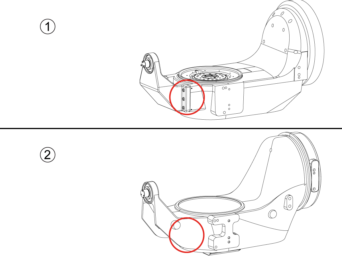
 Držač obratka
Držač obratka
Držač obratka -
 5-osna rješenja
5-osna rješenja
5-osna rješenja -
 Automatizacija
Automatizacija
Automatizacija
ŽELITE RAZGOVARATI S NEKIM?Haas tvornički dućan (outlet) (HFO) može odgovoriti na vaša pitanja i provesti vas kroz najbolje opcije.
CONTACT YOUR DISTRIBUTOR > -
-
Why Haas
Otkrijte Haas razliku
-
Servis
- Videozapisi


.png)