-
mașini
-
Freze verticale
Freze verticale
-
Soluții în mai multe axe
Soluții în mai multe axe
-
Strunguri
Strunguri
-
Freze orizontale
Freze orizontale
-
Unități rotative și indexoare
Unități rotative și indexoare
-
Sisteme de automatizare
Sisteme de automatizare
-
Mașini desktop
Mașini desktop
-
Echipament pentru atelier
Echipament pentru atelier
-
Mașini de producție
Mașini de producție
CUMPĂRAREA SCULELORAVEȚI NEVOIE DE CONSILIERE?O reprezentanță Haas (HFO) vă poate răspunde la întrebări și vă poate ghida spre cele mai bune opțiuni.
CONTACT YOUR DISTRIBUTOR > -
Freze verticale
-
Opțiuni
-
/2026-04-VOP-SquareComponent.jpg/_jcr_content/renditions/cq5dam.thumbnail.319.319.png) Pachetele cu opțiuni de valoare
Pachetele cu opțiuni de valoare
Pachetele cu opțiuni de valoare
Pachetele cu opțiuni de valoare -
 Arborii principali
Arborii principali
Arborii principali -
 Schimbătoare de scule
Schimbătoare de scule
Schimbătoare de scule -
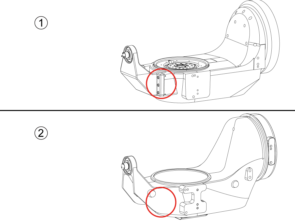
 Axa a 4-a | 5-a
Axa a 4-a | 5-a
Axa a 4-a | 5-a -
 Capete revolver și ansamblul sculelor antrenate
Capete revolver și ansamblul sculelor antrenate
Capete revolver și ansamblul sculelor antrenate -
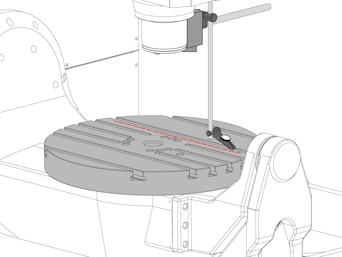
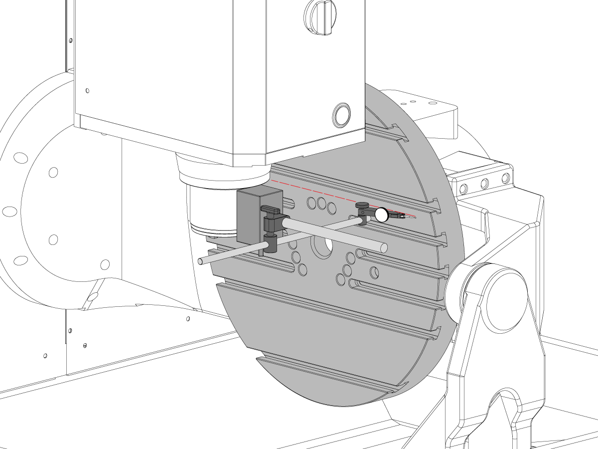
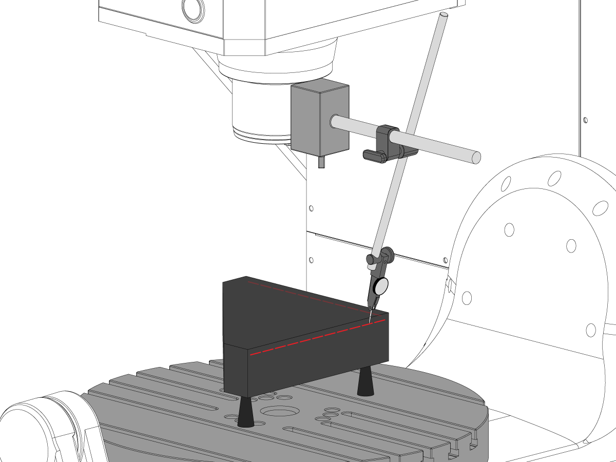
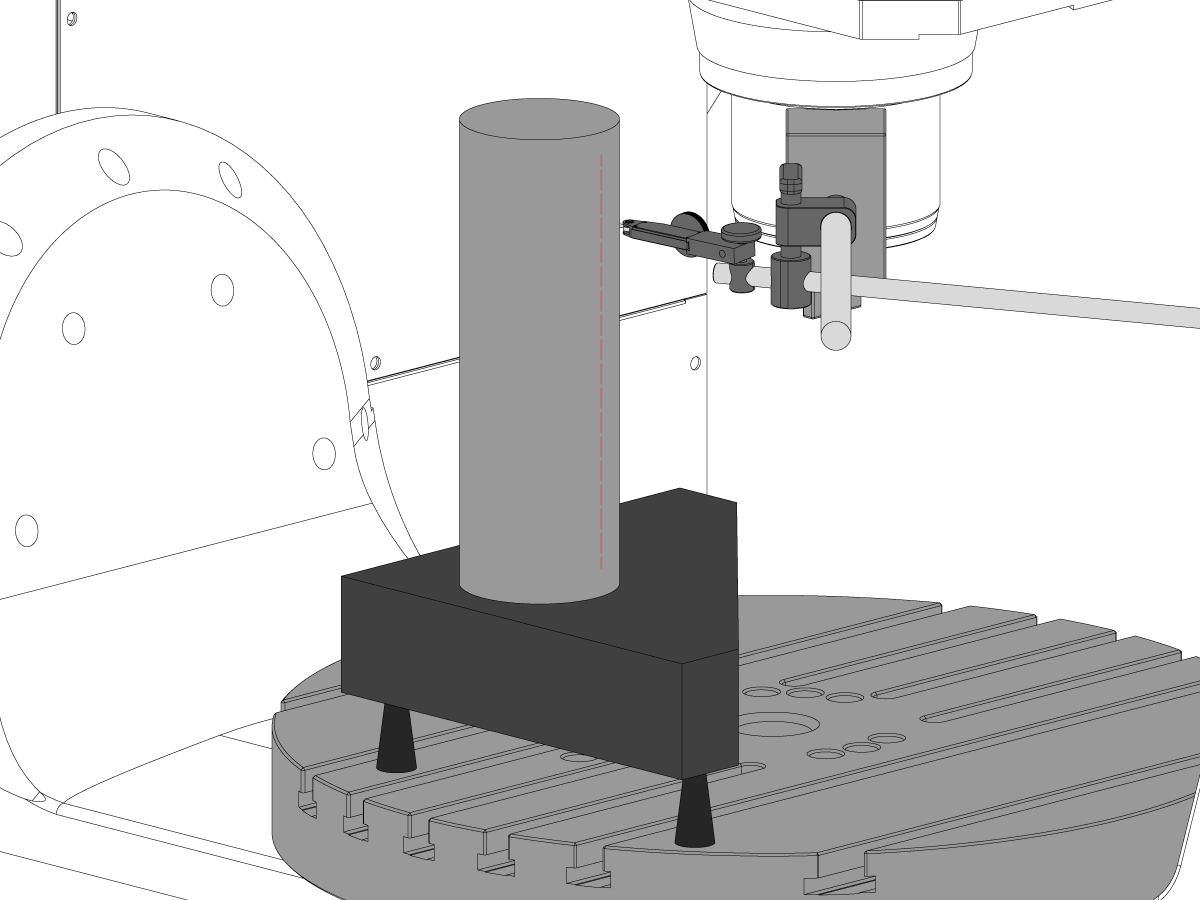
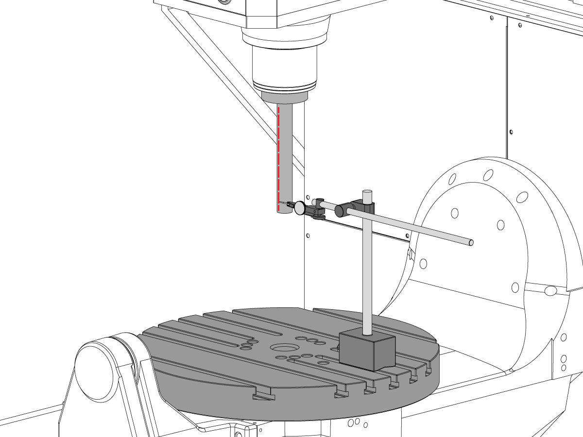
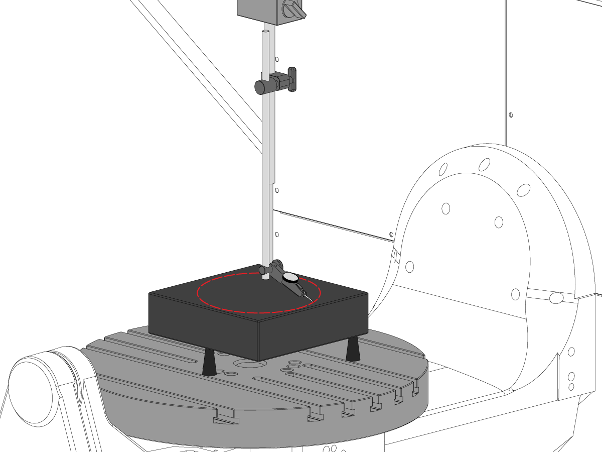
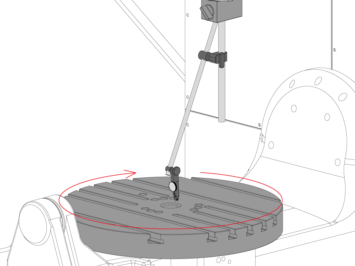
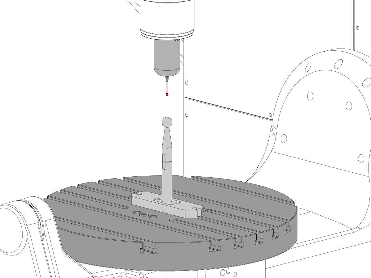
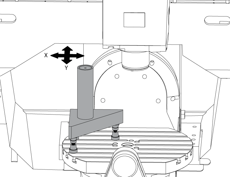
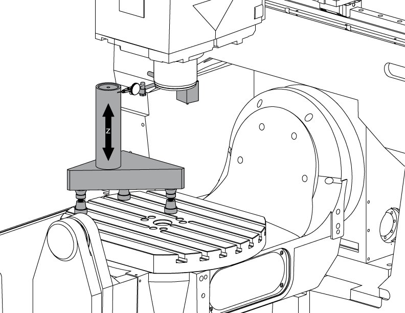
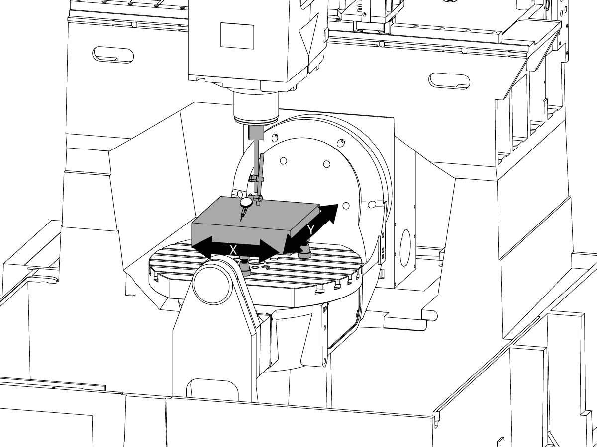
 Palpare
Palpare
Palpare -
 Gestionarea lichidului de răcire și șpanului
Gestionarea lichidului de răcire și șpanului
Gestionarea lichidului de răcire și șpanului -
 Unitatea de comandă Haas
Unitatea de comandă Haas
Unitatea de comandă Haas -
 Opțiunile produsului
Opțiunile produsului
Opțiunile produsului -
 Scule și dispozitive de fixare
Scule și dispozitive de fixare
Scule și dispozitive de fixare -
 Sistemul de suport piesă
Sistemul de suport piesă
Sistemul de suport piesă -
 Soluții în 5 axe
Soluții în 5 axe
Soluții în 5 axe -
 Automatizare
Automatizare
Automatizare
CUMPĂRAREA SCULELORAVEȚI NEVOIE DE CONSILIERE?O reprezentanță Haas (HFO) vă poate răspunde la întrebări și vă poate ghida spre cele mai bune opțiuni.
CONTACT YOUR DISTRIBUTOR > -
-
Why Haas
Descoperiți diferența Haas
-
Service
Bine ați venit la departamentul de Haas Service
- Videoclipuri
-
CUMPĂRAREA SCULELORAVEȚI NEVOIE DE CONSILIERE?
O reprezentanță Haas (HFO) vă poate răspunde la întrebări și vă poate ghida spre cele mai bune opțiuni.
CONTACT YOUR DISTRIBUTOR > -


.png)