×

Search Results

Web Pages

Images

    • <
    • 1
    • >
  • machines
    • Haas Vertical Mills
      Vertical Mills
      • Vertical Mills
      • VF Series
      • Universal Machines
      • VR Series
      • Pallet-Changing VMCs
      • Mini Mills
      • Mold Machines
      • Drill/ Tap/ Mill Series
      • Toolroom Mills
      • Compact Mills
      • Gantry Series
      • Vertical Mill/Turn
      • Extra-Large VMC
      • Double-Column Mills
      • Desktop Mill
      • Mill Auto Parts Loader
    • Product Image
      Multi-Axis Solutions
      • Multi-Axis Solutions
      • Y-Axis Lathes
      • 5-Axis Mills
    • Haas Lathes
      Lathes
      • Lathes
      • ST Series
      • Dual-Spindle
      • Toolroom Lathes
      • Chucker Lathe
      • Haas Bar Feeder V2
      • Lathe Auto Parts Loader
    • Haas Horizontal Mills
      Horizontal Mills
      • Horizontal Mills
      • 50-Taper
      • 40-Taper
    • Haas Rotaries & Indexers
      Rotaries & Indexers
      • Rotaries & Indexers
      • Rotary Tables
      • Indexers
      • 5-Axis Rotaries
      • Extra-Large Rotaries
    • Product Image
      Automation Systems
      • Automation Systems
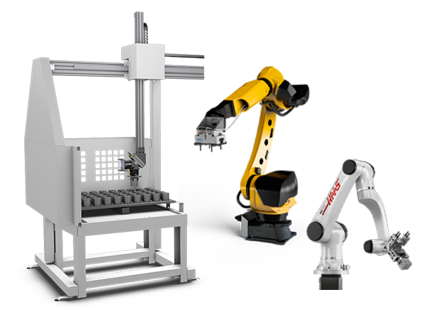
      • Robot Systems
      • Automatic Parts Loaders
      • Pallet-Pool Systems
      • Haas Bar Feeder
      • Models
    • QUICK LINKS Special Series  Special Series 
      HAAS CAREERS HAAS CAREERS BUILD & PRICE BUILD & PRICE PRICE LIST PRICE LIST WHAT’S NEW WHAT’S NEW YOUR FIRST CNC YOUR FIRST CNC HAAS SIX PACK HAAS SIX PACK
      SHOPPING TOOLS
      • Build & Price a Haas
      • Price List
      • Available Inventory
      • CNCA Financing
      WANT TO TALK TO SOMEONE?

      A Haas Factory Outlet (HFO) can answer your questions, and walk you through your best options.

      CONTACT YOUR DISTRIBUTOR >
  • Options
    • Product Image
      Spindles
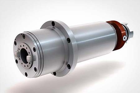
      • Spindles
    • Product Image
      Tool Changers
      • Tool Changers
    • Product Image
      4th- | 5th-Axis
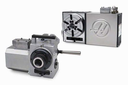
      • 4th- | 5th-Axis
    • Product Image
      Turrets & Live Tooling
      • Turrets & Live Tooling
    • Product Image
      Probing
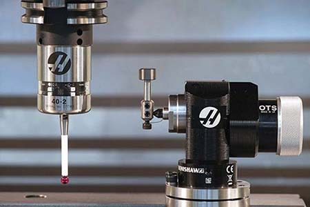
      • Probing
    • Haas Chip & Coolant Management
      Chip & Coolant Management
      • Chip & Coolant Management
    • The Haas Control
      The Haas Control
      • The Haas Control
    • Product Image
      Product Options
      • Product Options
    • Product Image
      Tooling & Fixturing
      • Tooling & Fixturing
    • Product Image
      Workholding
      • Workholding
    • Product Image
      5-Axis Solutions
      • 5-Axis Solutions
      • 5 Easy Steps to 5-Axis
    • Product Image
      Automation
      • Automation
    • QUICK LINKS Special Series  Special Series 
      HAAS CAREERS HAAS CAREERS BUILD & PRICE BUILD & PRICE PRICE LIST PRICE LIST WHAT’S NEW WHAT’S NEW YOUR FIRST CNC YOUR FIRST CNC HAAS SIX PACK HAAS SIX PACK
      SHOPPING TOOLS
      • Build & Price a Haas
      • Price List
      • Available Inventory
      • CNCA Financing
      WANT TO TALK TO SOMEONE?

      A Haas Factory Outlet (HFO) can answer your questions, and walk you through your best options.

      CONTACT YOUR DISTRIBUTOR >
  • Why Haas
      Discover the Haas Difference
      Why Haas MyHaas Education Community Industry 4.0 Haas Certification Customer Testimonials
  • Service
      Welcome to Haas Service
      SERVICE HOME Operator’s Manuals How-To Procedures Troubleshooting Guides Preventive Maintenance Haas Parts Haas Tooling Videos
  • Videos
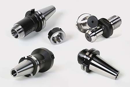
  • Haas Tooling
      Haas Tooling Mill Toolholding Mill Workholding Milling Lathe Tooling Lathe Toolholding Lathe Workholding ER Collets & Chucks Holemaking Threading Tool Management Tooling Accessories Package Kits Measuring & Inspection Apparel & Accessories
      HAAS TOOLING QUICK LINKS
      NEW PRODUCTS NEW PRODUCTS
      MOST POPULAR MOST POPULAR
      OPEN TERMS OPEN TERMS
      FINANCING FINANCING
      FAQs FAQs
      KITS CREATED FOR YOU KITS CREATED FOR YOU
  • Haas Service Parts
      Haas Service Parts Automatic Pallet Changer Automatic Tool Changer Chip Management Coolant Counterbalance Electrical Cabinet Enclosure Field Install Options Hydraulics Lubrication Maintenance Pendant Probing Rotary Spindle Tailstock
  • Contact Us

My Cart
MyHaas Welcome,
!
Haas Tooling Guest Order History MyHaas/HaasConnect Sign In Register Haas Tooling My Account Order History Return History MyHaas/HaasConnect Sign Out Welcome, My Machines Latest Activity My Quotes My Account My Users Sign Out
Find A Dealer
  1. Select Language
    1. English
    2. Deutsch
    3. Español
    4. Français
    5. Italiano
    6. Português
    7. Český
    8. Dansk
    9. Nederlands
    10. Magyar
    11. Polski
    12. Svenska
    13. Русский
    14. Türkçe
    15. 中文
    16. Suomi
    17. Norsk
    18. الإنجليزية
    19. български
    20. Hrvatski
    21. Ελληνικά
    22. Română
    23. Slovenský
    24. Slovenščina
    25. 한국어
    26. 日本語
Search
×

Search Results

Web Pages

Images

    • <
    • 1
    • >

9 - UMC - MRZP and Safe Zones

UMC-Series - Service Manual


  • 1 - UMC - Introduction
  • 2 - UMC - Specifications
  • 3 - UMC-500/750/1000 - Installation
  • 4 - UMC-1500-DUO/1600-H - Installation
  • 5 - UMC - Anchoring
  • 6 - UMC - Operation
  • 7 - UMC - Geometry and Alignment
  • 8 - UMC - Axis Compensation
  • 9 - UMC - MRZP and Safe Zones
  • 10 - UMC - B/C - Rotary Axis
  • 11 - UMC - Tool Changer
  • 12 - UMC - Chip Removal and Coolant
  • 13 - UMC - Electrical Control
  • 14 - UMC - Lubrication
  • 15 - UMC - Maintenance
  • 16 - UMC - Pallet Pool
  • 17 - UMC - Hydraulic Workholding
  • 18 - UMC - Pneumatic Workholding

Go To :

  • 9.1 MRZP/DWO Feature
  • 9.2 UMC 500/750/1000 - MRZP WIPS OFFSETS SETTINGS
  • 9.3 UMC-750P - MRZP WIPS OFFSETS SETTINGS
  • 9.4 MRZP A-C or B-C Axis Rough Set
  • 9.4 UMC Safe Zone Calibration

Introduction

The DWO feature in the Haas control is a very powerful tool but understanding the limits and the benefits is absolutely critical to success.

The old way of doing things:

A typical multi-face setup requires that the fixture datum be located precisely on the center of rotation of the rotary axis. Then the job is usually programmed with a unique work offset for each face. If the programmer moves one of the offsets then he needs to recalculate and translate each of the other offsets. This is reasonably straight-forward if the part is square and the work offsets are at the 90-degree faces. It gets a lot more complicated when there are features at odd angles – and an order of magnitude worse when there are compound angles involved. If the fixture is removed and reinstalled then the whole setup process starts over again and each work offset gets reset. If the castings aren’t cleaning up and the machinist wants to move the datum face in 0.010” then all of the other work offsets get recalculated and reset.

Haas Dynamic Work Offsets

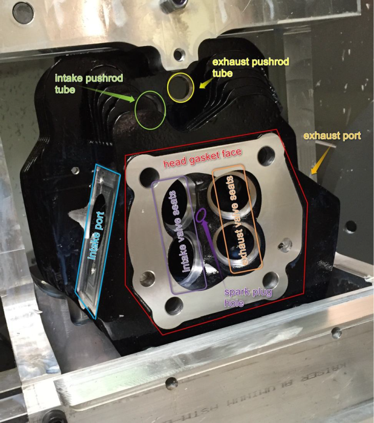
The DWO functionality makes all of these problems disappear on the right kind of job. Consider the cylinder head pictured to the left. The combustion chamber side of the casting has features machined from eight different angles. The rocker shaft side of the head has features at two more orientations. That’s ten different work offsets to manage.

If this job is programmed and set up using DWO then all features are referenced back to a single work offset. If the head gasket face doesn’t clean up simply move the work offset in 0.010” and all of the other features move along with it; no changes to the CNC program or to other work offsets are required. If the fixture is removed and reinstalled the machinist simply needs to probe the original datum (or probe a known tooling point on the fixture) to re-establish G54 and the job can be back up and running in minutes.

What are the limitations?

The Haas DWO function relies on a very accurate measurement of the relationship between the B-axis and the C-axis. This relationship is heavily dependent on how precisely the machine is leveled. The UMC is configured with probing as a standard feature and the CNC control has a conversational probing template that walks the user through the process of recalibrating MRZP offsets that drive the DWO calculations. Bear in mind that the process is only as accurate as the results of the probing cycle. The WIPS work probe is extraordinarily accurate, but it is not a laboratory-grade inspection device – nor is the inside of a machine enclosure as clean as a laboratory. It is reasonable to expect a couple tenthousandths of an inch of error one way or the other when probing the included calibration tooling ball. The MRZP calculations probe the ball at many different locations to minimize the effects of these tiny probing errors, but there might be small amounts of error nonetheless.

Recognize also that the B- and C-axes of the machine are remarkably accurate; but like the work probe, they aren’t perfect. No rotary table from any manufacturer is. Understand that an angular positioning error of 20 arc-seconds, while tiny, turns into a linear positioning error of 0.001” at 10” from center and 0.002” at 20” from center.

If the MRZP offsets have 0.0005” of error in the X-axis direction then a hole bored halfway through a part at B90 and then finished from the other side of the part at B-90 would have 0.001” mismatch just from the slight inaccuracies in the MRZP offsets. But B-90 is outside of the travel limits of the UMC. This kind of feature needs to be machined halfway through at B90 and C0, and then finished at B90 and C180. So now the part might have a small true position error along the X-axis from any inaccuracy in the MRZP X-axis and Z-axis offsets combined with a small mismatch from both sides in the Y-axis direction from any inaccuracy in the MRZP y-axis offset. Now add in any small deviation that could come from B axis and C-axis positioning errors and it is easy to see that true positional errors of a few thousandths of an inch aren’t unreasonable when using the machine this way.

Understand the trade-offs and help the customer make the right decision

If the customer’s job has reasonable milling machine tolerances of +/- a couple thousandths of an inch then DWO is a good choice. If the customer is going to tear his job down and set is back up frequently then DWO is a good choice. If the customer’s job requires exquisite true-positional accuracy then DWO is not a good choice. This job probably requires individual work offsets for each face. If the customer wants to use DWO for this job he still can, but he needs to accept the compromises he will have to make. He might need to manually adjust his MRZP offsets. He might need to adjust some of the programmed points in his CNC program.

How To - MRZP Offset Settings

MRZP WIPS Offsets Settings

1

This tells you how to set Machine Rotary Zero Point (MRZP) Offsets. The MRZP Offsets are settings in the Haas CNC control that tell the control these distances:

  1. the distance of the tilt axis (B axis) centerline from the X-Axis home position
  2. the distance of the tilt axis (B axis) centerline from the Z-Axis home position
  3. the distance of the table rotary axis (C axis) centerline from the Y-Axis home position

This procedures shows images that use both calibration assemblies.

 Important: The spindle probe must be calibrated before doing this procedure. This makes sure the accuracy of the probe to the machine position is correct. Refer to the Next Generation Control - Probe Calibration (VPS) procedure, in the diy.haascnc.com

2

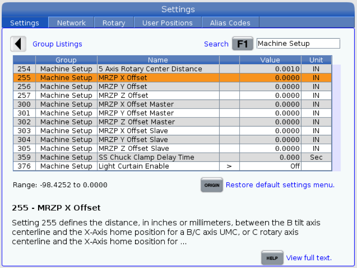
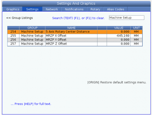
Press [Setting] and navigate to Machine Setup. Check setting 255, 256, and 257. The values should not be zero. If they are perform the following procedure.

MRZP A-C or B-C Axis Rough Set

3

[ZERO RETURN] [ALL] axes.

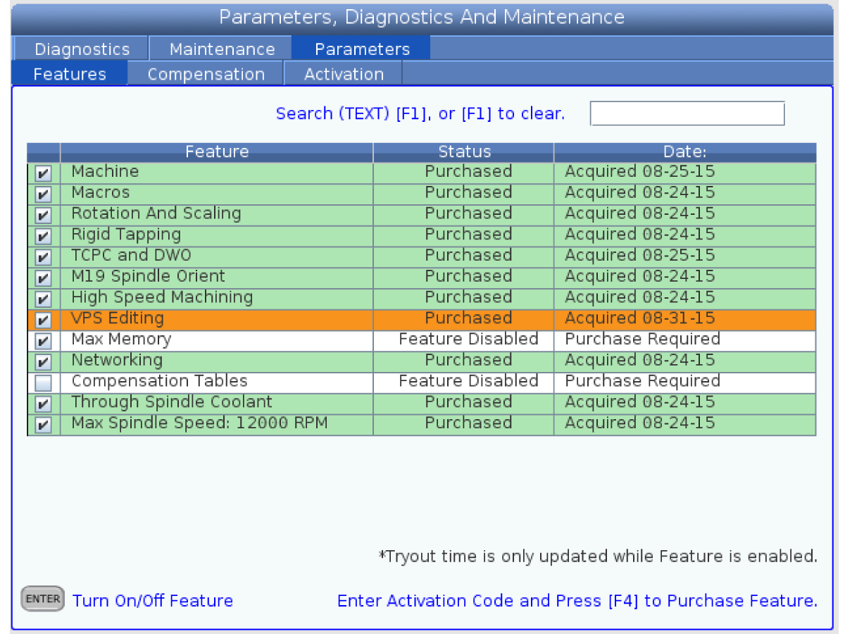
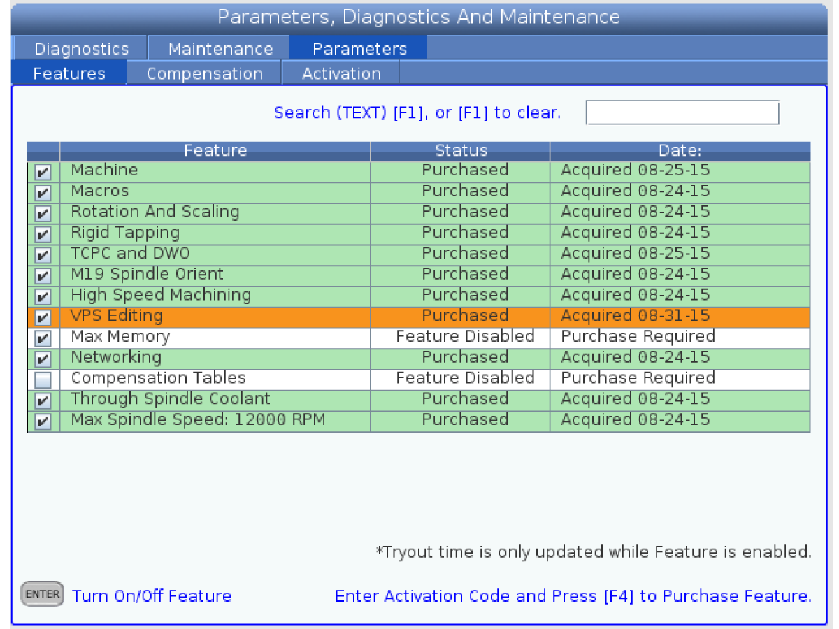
Go to Features tab in [DIAGNOSTIC] and make sure the VPS Editing is on.

Put the work probe in the spindle.

Push [EDIT] button.

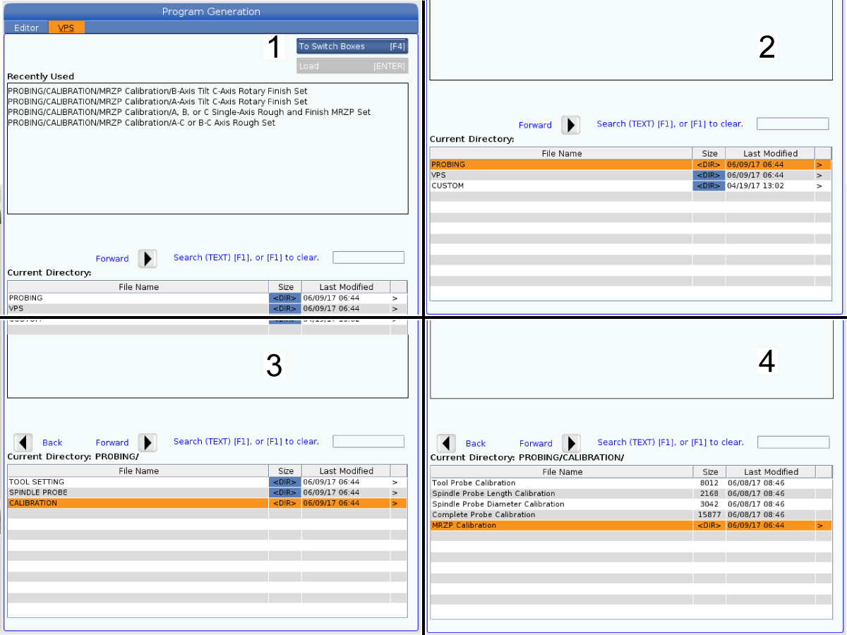
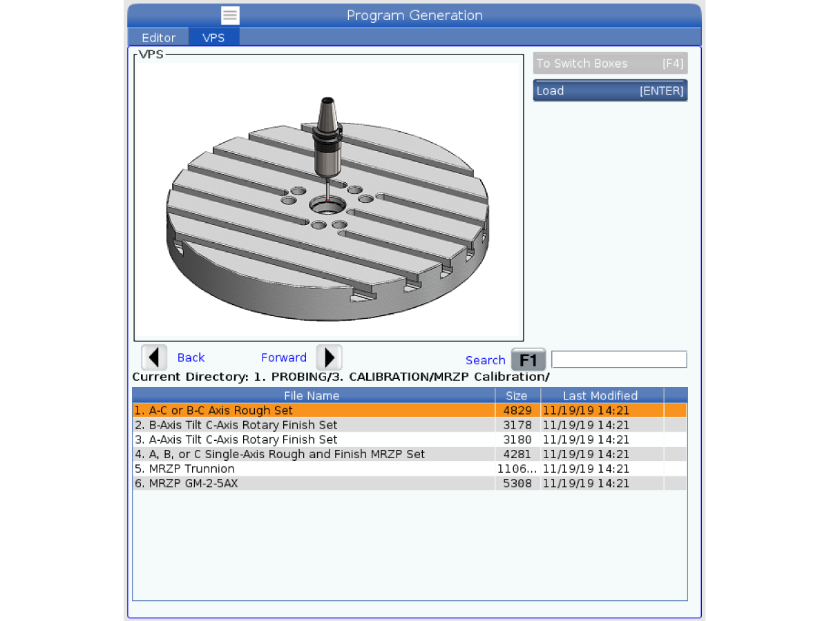
Select VPS .

Push the [DOWN] cursor arrow to PROBING [1].

Select CALIBRATION [2]. Push the [RIGHT] cursor arrow.

Select MRZP CALIBRATION [3].

4

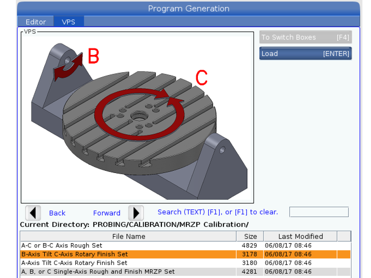
Push the [DOWN] cursor arrow and select B-AXIS TILT C-AXIS ROTARY FINISH SET.

Note: A-C Or B-C MRZP ROUGH SET is used only when there are no MZRP offset settings (255, 256, 257) set.

5

Enter the diameter of the tooling ball [2].

Important: Always measure the tooling ball with a calibrated micrometer to ensure the correct ball diameter.

 Note: If you are in metric mode make sure you enter the ball size in millimeters. If you are in inch mode enter the ball size in inches

Push [ENTER] .

Push [F4] .

Select Output MDI .


6

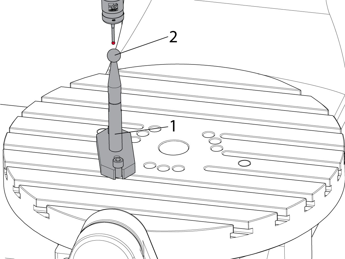
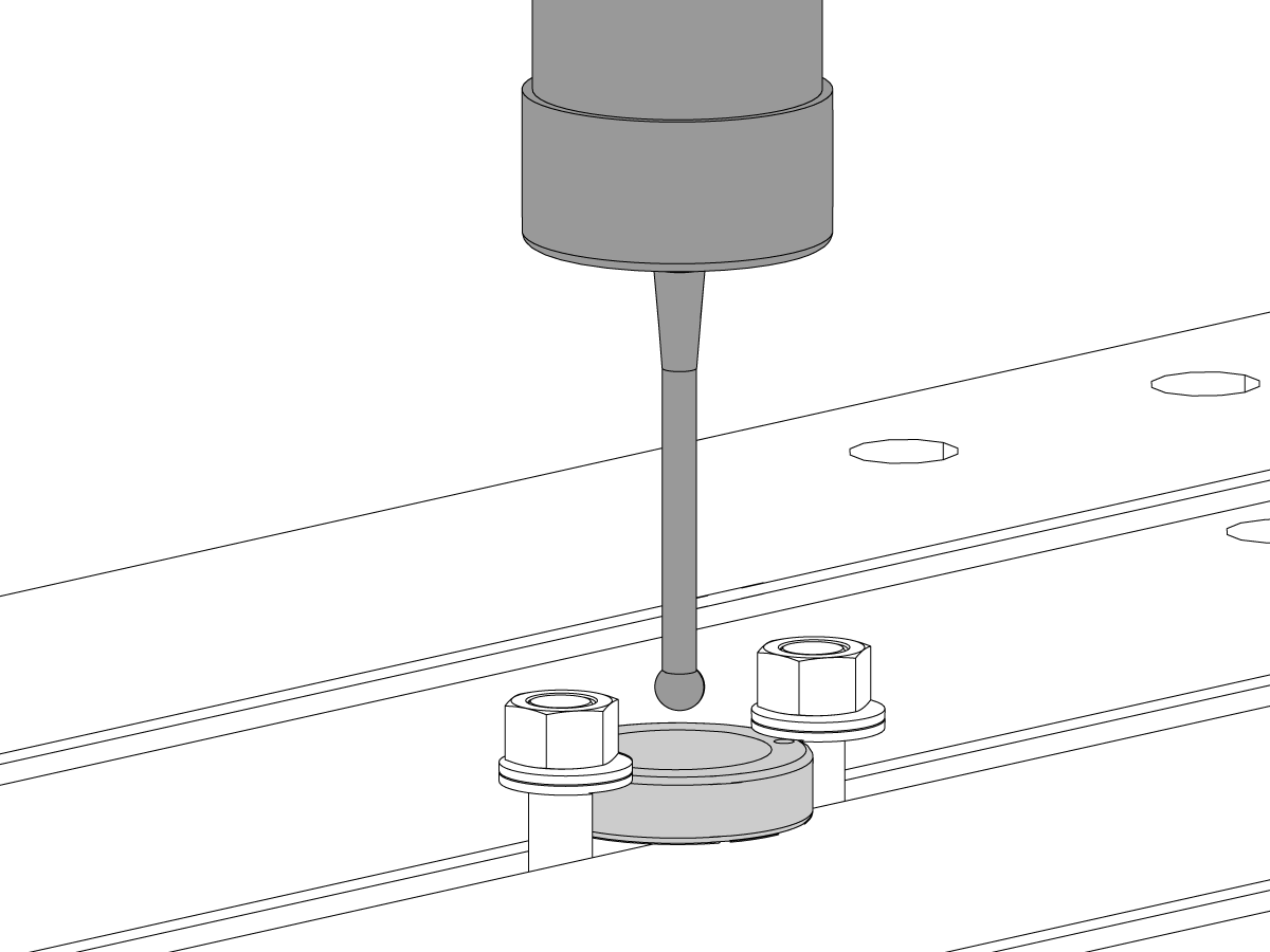
Install the calibration sphere assembly [1] near the center of the X Axis.

Note:  On a UMC-1000 if the calibration sphere is too far out from the center, an overtravel alarm will be generated during the MRZP calibration cycle.

Make sure that the tooling ball [2] is tightly attached to the calibration assembly.

Note:  On a UMC machines that are equipped with the Pallet Pool the calibration sphere will need to be secured to the pallet using toe clamps.

Note: Do not over tighten the tooling ball.

Jog the Z Axis until the probe tip [2] is 0.1" (2.54 mm) above and centered over the tooling ball [1].

Start the program in MDI. This program is O099994 B AXIS TILT AND C AXIS ROT AXIS .

7

The probe measures many positions on the B and C axes at different degrees.

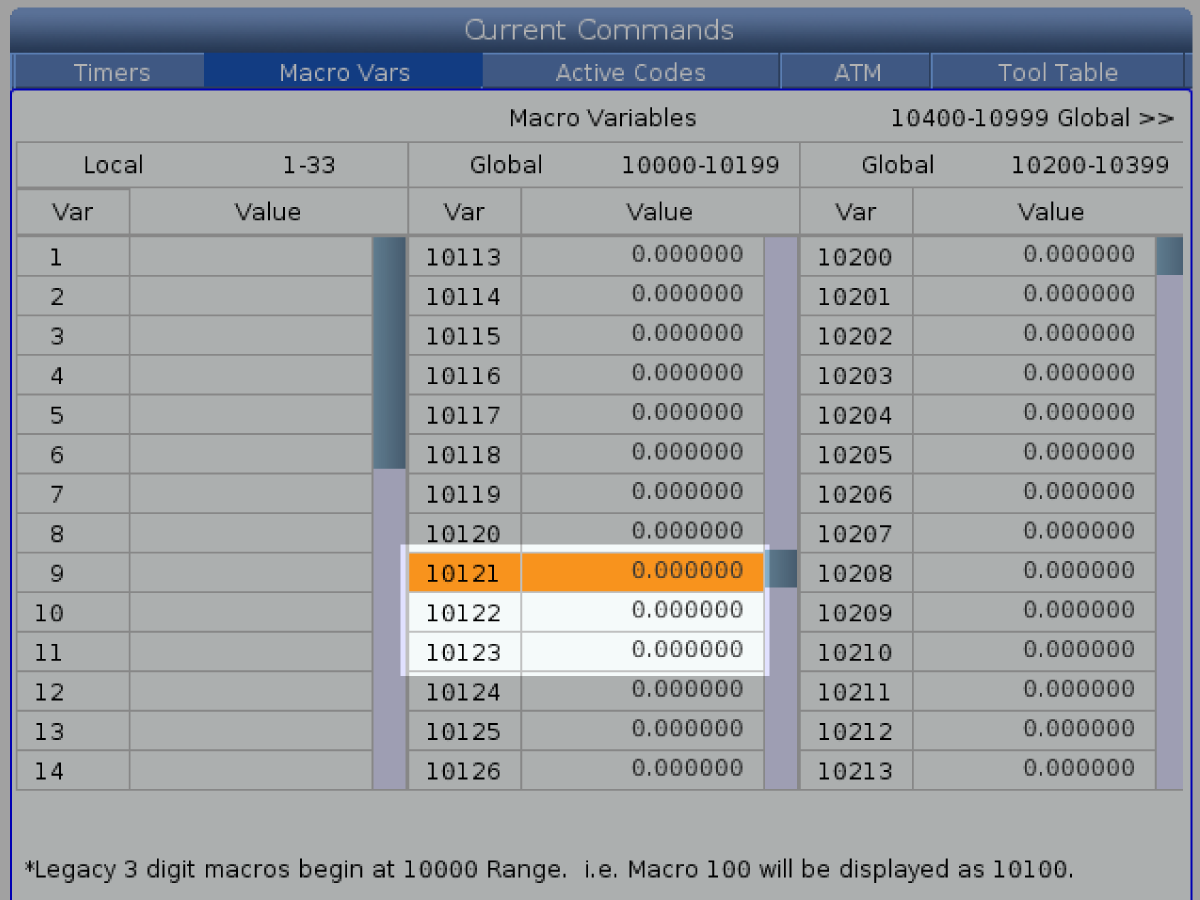
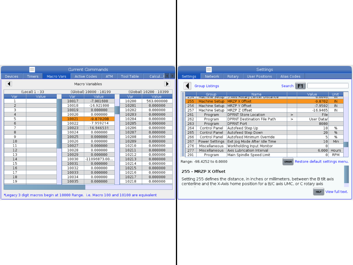
The program puts values in macro variables 10121, 10122, and 10123. Record those values.

8

Put the recorded values in these settings:

  • Enter the value for macro variable 10121 in setting 255; MRZP X Offset.
  • Enter the value for macro variable 10122 in setting 256; MRZP Y Offset.
  • Enter the value for macro variable 10123 in setting 257; MRZP Z Offset.

If you think that you possibly entered incorrect numbers, start the MRZP FINISH SET program again. The values that the program puts into the variables must be within five counts or less of the setting numbers.

 Note: Setting 9 determines if the values are shown in inches or millimeters.

Prerequisites

1

The probing system needs to be calibrated before performing this procedure.

Macro variables #10300; #10301; #10302; #10303; #10304; #10305 should be set to zero.

Work offsets G154 P80 / G154 P81 / G154 P82 are used to store the probing information, make sure they are cleared before starting the process.

TCPC / DWO needs to be enabled.

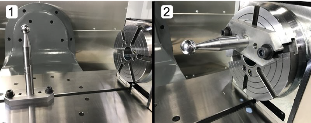
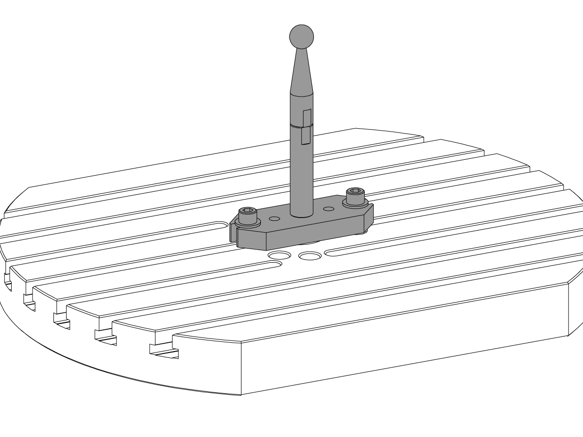
Setup the artifact as shown in the picture. For B axis [1] and A axis [2].

Recommended probing position are:

  • For the B axis: B-20°, B 0°, B+20°.
  • For the A axis: A 0°, A+90° A+180°


Perform the following steps for each rotary axis. In the event of alarm during the process refer to the Troubleshooting section at the end of the document.

UMC-750P - Single Axis MRZP Set

1

Setup the artifact.

Place the spindle probe in the spindle.

Install the Calibration Sphere Assembly onto the platter. Refer to prerequisites for the location.

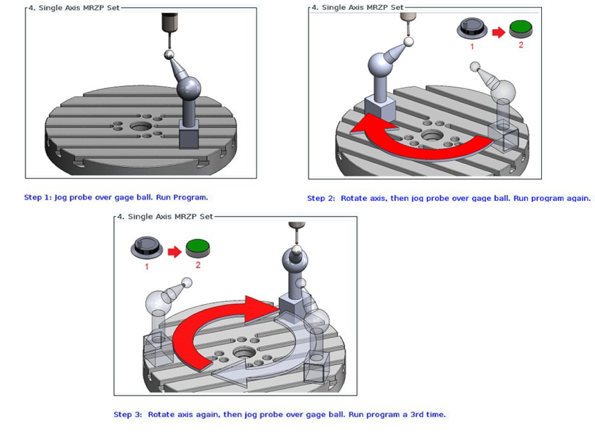
Note: You will probe the sphere 3 times with the rotary at 3 different positions. Make sure that the Sphere will stay within XYZ tarvel limits when attempting to run the probing cycle at different angles.

Jog the rotary axis in the position for the first cycle

Jog X and Y axis to align the probe tip with the center of the sphere within 0.1".

Jog the Z axis to position the probe tip 0.25 away from the sphere surface.

2

Generate the program.

Press EDIT and cursor over to the VPS tab.

Navigate into MRZP Calibration folder: PROBING ➡ CALIBRATION ➡ MRZP Calibration.

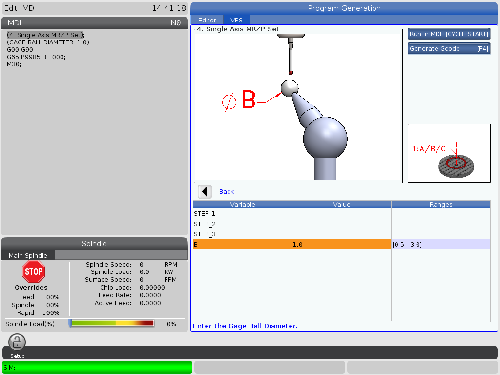
Open the A, B, or C Single - Axis Rough and Finish MRZP Set template.

In the template, STEP_1, STEP_2, STEP_3 are instructions on how to run the probing cycle.

Cursor down to B and enter the Calibration Sphere diameter.

Press Cycle Start to run the pogram in MDI or F4 for more options.

3

Run the probing cycles.

Run the probing cycle with the rotary at first position

When the first cycle is done, jog the the rotary to the second position.

Jog X and Y axis to align the probe tip with the center of the sphere within 0.1".

Jog the Z axis to position the probe tip 0.25 away from the sphere surface.

Run the same program again.

When the second cycle is done, jog the rotary to the third position.

Jog X and Y axis to align the probe tip with the center of the sphere within 0.1".

Jog the Z axis to position the probe tip 0.25 away from the sphere surface.

Run the same program for the third time.

After the last probing cycle Z axis will be sent to the Home position and control will output the MRZP offsets into the macro viraibles.

4

Enter the MRZP settings.

The control will calculate and output the Rotary Zero Points for master or slave rotary into the macro variables depending on the rotary settings configuration.

You do not need to specify which axis you run the MRZP for. The control will populate the MRZP macros based on the results of the 3 probing cycles. For example: if during 3 probe cycles at diferent rotary positions Y and Z coordinates for the center of the sphere has changed and the X axis coordinate stayed within 0.002" then the rotary rotates about the X axis.

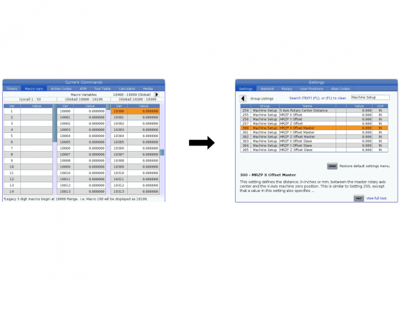
Enter the values from the macro variables into the settings as follows:

  • Macro variable #10300 represents the setting 300 MRZP X Offset Master
  • Macro variable #10302 represents the setting 302 MRZP Z Offset Master
  • Macro variable #10304 represents the setting 304 MRZP Y Offset Slave
  • Macro variable #10305 represents the setting 305 MRZP Z Offset Slave

Troubleshooting

List of the alarms that could be generated when running MRZP set.

  • SETTING 254 MUST BE SET TO ZERO FOR ACCURATE MRZP VALUES. The program checks if there is a value in the setting 254. Set the setting 254 to zero
  • PROBE IS NOT CALIBRATED / PLEASE CALIBRATE PROBE AND START PROCESS OVER. The program checks if the probe is calibrated. Calibrate the probe.
  • CALIBRATION UNIT IS TOO CLOSE THE CENTERLINE OF ROTATION PLEASE ADJUST IT AND START THE PROCESS OVER. The center of the calibration sphere is too close to the centreline of the rotary. Move the calibration sphere assembly away from the centreline of the rotary and start the process over.
  • ERROR / PLEASE INDICATE YOUR ROTARY SURFACE FLAT OR STRAIGHT WITHIN .002" / RESET YOUR TOOL CHANGE OFFSET IF NEEDED. The rotary is not squared to XYZ axes. Indicate the platter surface within 0.002"/ reset the toolchange offset for the tilting axis.
  • UNEXPECTED SURFACE FOUND. The probe tip is not aligned to the center of the calibration sphere within +/-0.1" / The probe tip is too close to the surface of the sphere. Position the probe stylus near the centreline of the calibration sphere within +/- 0.1" and 0.25" away from the surface of the sphere.
  • PROBING CYCLE IS COMPLETE / MRZP VALUES SETTING 255=#10121/ SETTING 256=#10122/ SETTING 257=#10123/ RUN THE PROGRAM AGAIN TO CLEAR MACROS AND OFFSETS USED DURING THIS PROCESS. The macro variable #10800 is not zero / work offsets G154 P80; G154 P81; G154 P82 is not zero. Reset the alarm and run the program again, in the next cycle program will clear the values.
  • MACROS AND OFFSETS HAVE BEEN CLEARED YOU MAY BEGIN TO PROBE THE NEXT AXIS. The program has cleared the values mentioned above. Reset the alarm and run the program again.

Introduction

This tells you how to set Machine Rotary Zero Point (MRZP) Rough Offsets. The MRZP Offsets are settings in the Haas CNC control that tell the control these distances:

  1. the distance of the tilt axis (B axis) centerline from the X-Axis home position
  2. the distance of the tilt axis (B axis) centerline from the Z-Axis home position
  3. the distance of the table rotary axis (C axis) centerline from the Y-Axis home position

Important: The spindle probe must be calibrated before doing this procedure. This makes sure the accuracy of the probe to the machine position is correct. Refer to the NEXT GENERATION CONTROL - PROBE CALIBRATION (VPS)

MRZP A-C or B-C Axis Rough Set

1

After calibrating the probe zero return all axes by pressing [ZERO RETURN], then [ALL], and then [A].

Check to see if VPS Editing is enabled by pressing [DIAGNOSTIC] and navigate to Parameters, then to Features. If it is not enabled contact your local HFO.

2

To calibrate MRZP press [EDIT] and navigate to VPS, then Probing, then Calibration, and then to MRZP Calibration. 

Select A-C or B-C Axis Rough Set

3

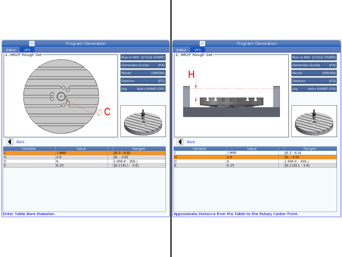
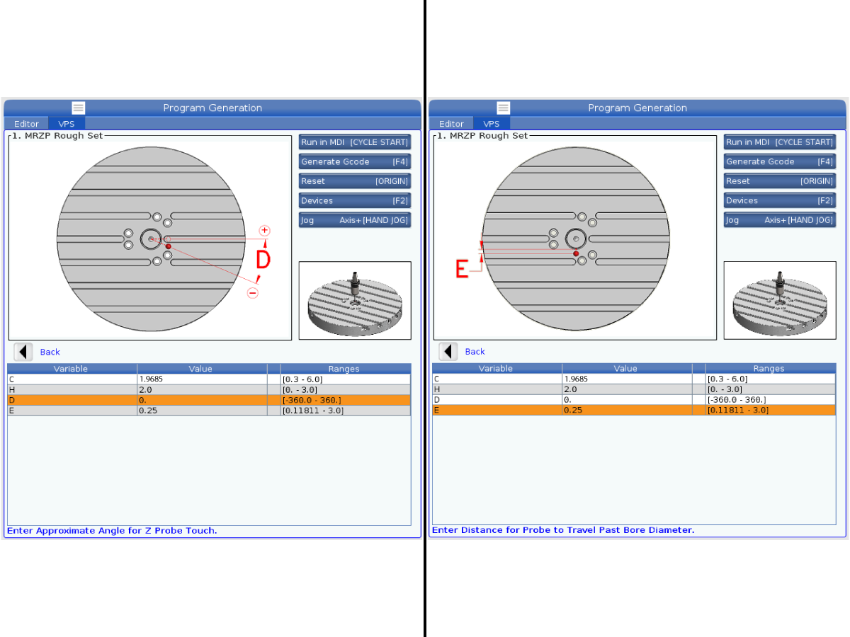
Dimension the Center Bore and set C equal to the Center Bore diameter.

Note: The Center Bore diameter may vary depending if the machine has a standard platter or Pallet Pool option.

Set H equal to the distance from the table to the rotary center point

  • All Non Pallet Pool UMC's = 2.0"
  • UMC-1000 Pallet Pool = 0.0"

4

Set D Approximate Angle for Z Probe Touch equal to 0.0

Set E Distance for Probe to Travel Past Bore Diameter equal to 0.25


5

Jog Probe to .1" above center of Platter Bore.

Press [CYCLE START] to begin probing cycle.

6

After the program is completed press [Current Commands] and navigate to Macro Variables.

Record the values for macro variables 10121, 10122, and 10123.

Press [Setting] and navigate to Machine Setup.

  • Go to setting 255 MRZP X Offset and enter the value for macro variable 10121.
  • Go to setting 256 MRZP Y Offset and enter the value for macro variable 10122.
  • Go to setting 257 MRZP Z Offset and enter the value for macro variable 10123.
Recently Updated

UMC Safe Zone - Calibration


Safe Zone Calibration

1

This tells you how to set Safe Zone Offsets. 

This procedures shows images that use both calibration assemblies.

 Important: The spindle probe must be calibrated before doing this procedure. This makes sure the accuracy of the probe to the machine position is correct. Refer to the Next Generation Control - Probe Calibration (VPS) procedure, in the diy.haascnc.com

2

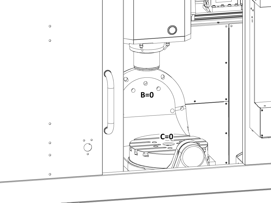
Return the B and C axis to its home position.

Command the spindle probe into the spindle.

3

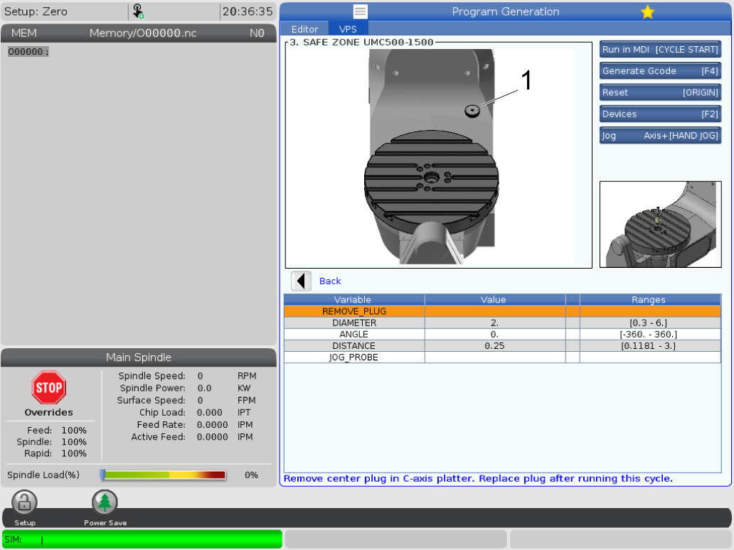
Press [EDIT] and navigate to the VPS tab. Press the [RIGHT ARROW] key and remove the center bore plug as prompted in the calibration set up.  

4

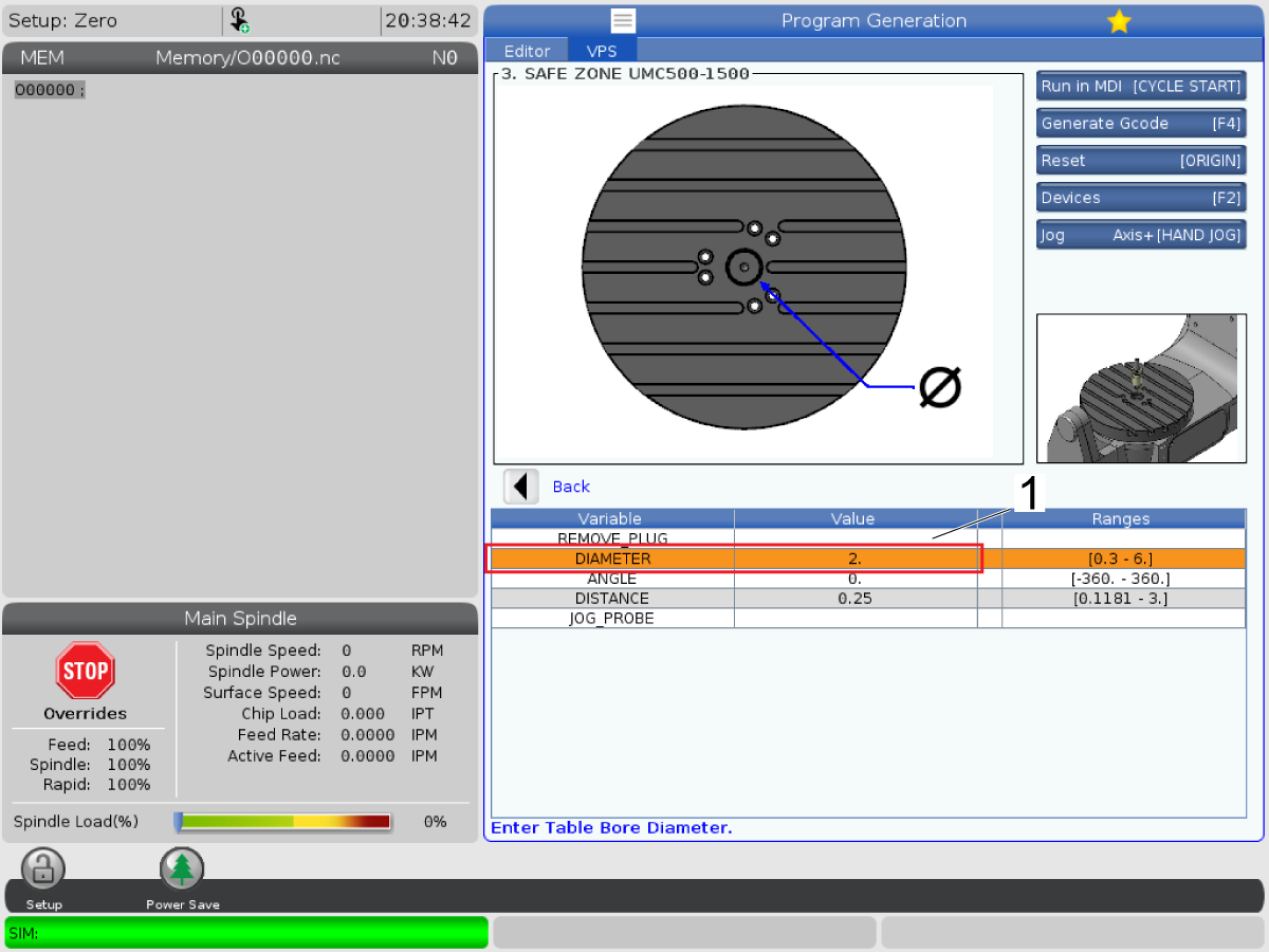
Input the approximate diameter of the center bore, use calipers to double check. 

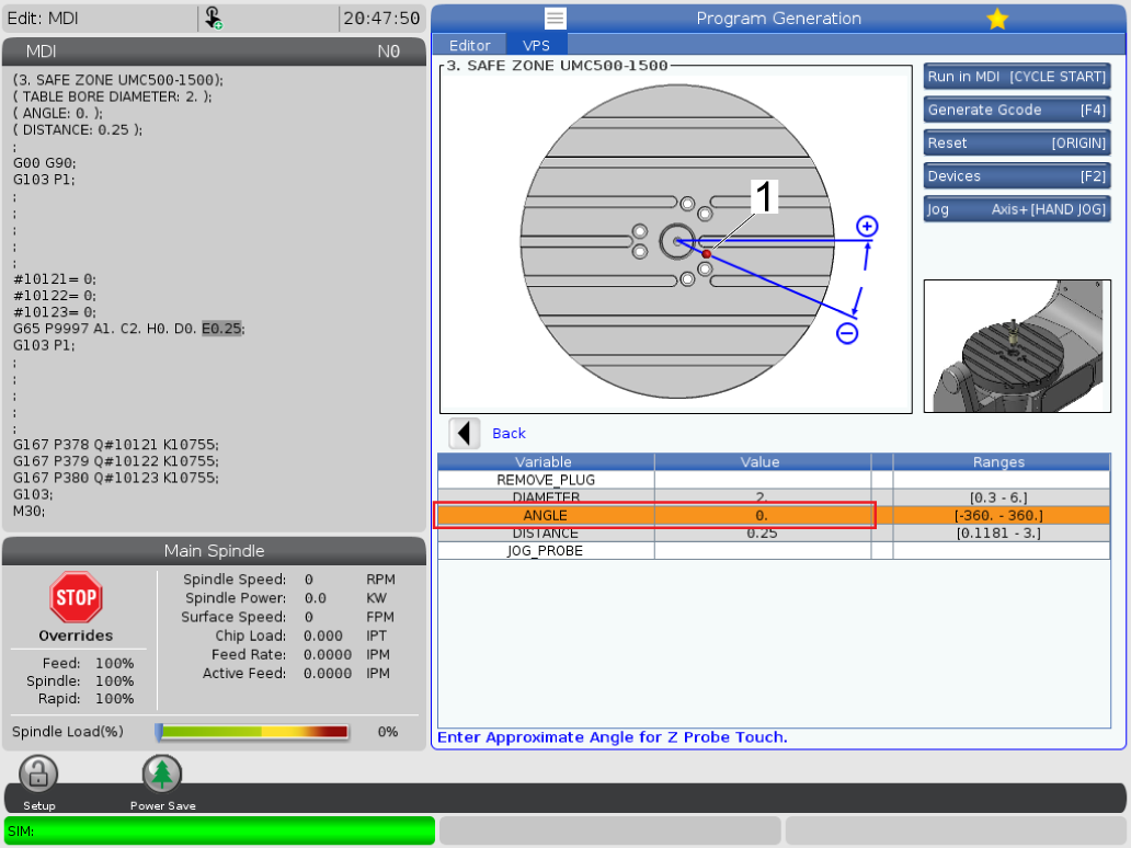
5

This input  is to set the angle at which the probe will come out before moving down to touch the platter. 

NOTE: This input is to avoid the probe incorrectly touching any of the platter plugs or missing the platter by going down in the T-slots instead. 

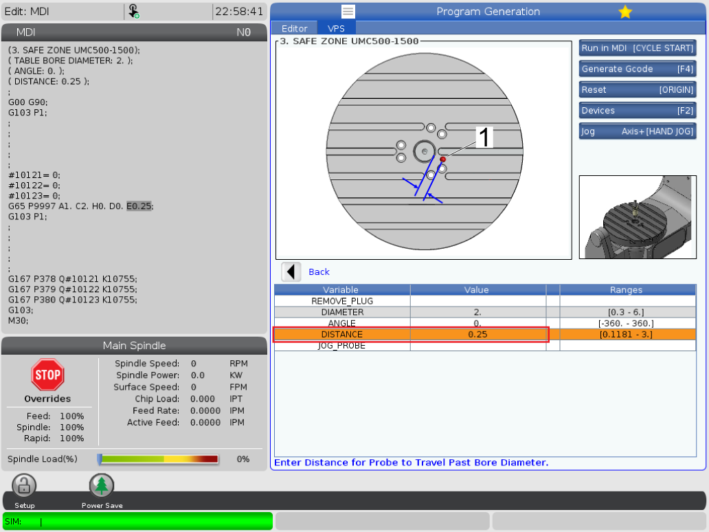
6

This input is to set the distance at which the probe will come out before moving down to touch the platter. 

 NOTE: This input works similar to the angle input as it is  to avoid the probe incorrectly touching any of the platter plugs or missing the platter by going down in the T-slots instead. Both inputs are needed to avoid plugs or T-slots. 

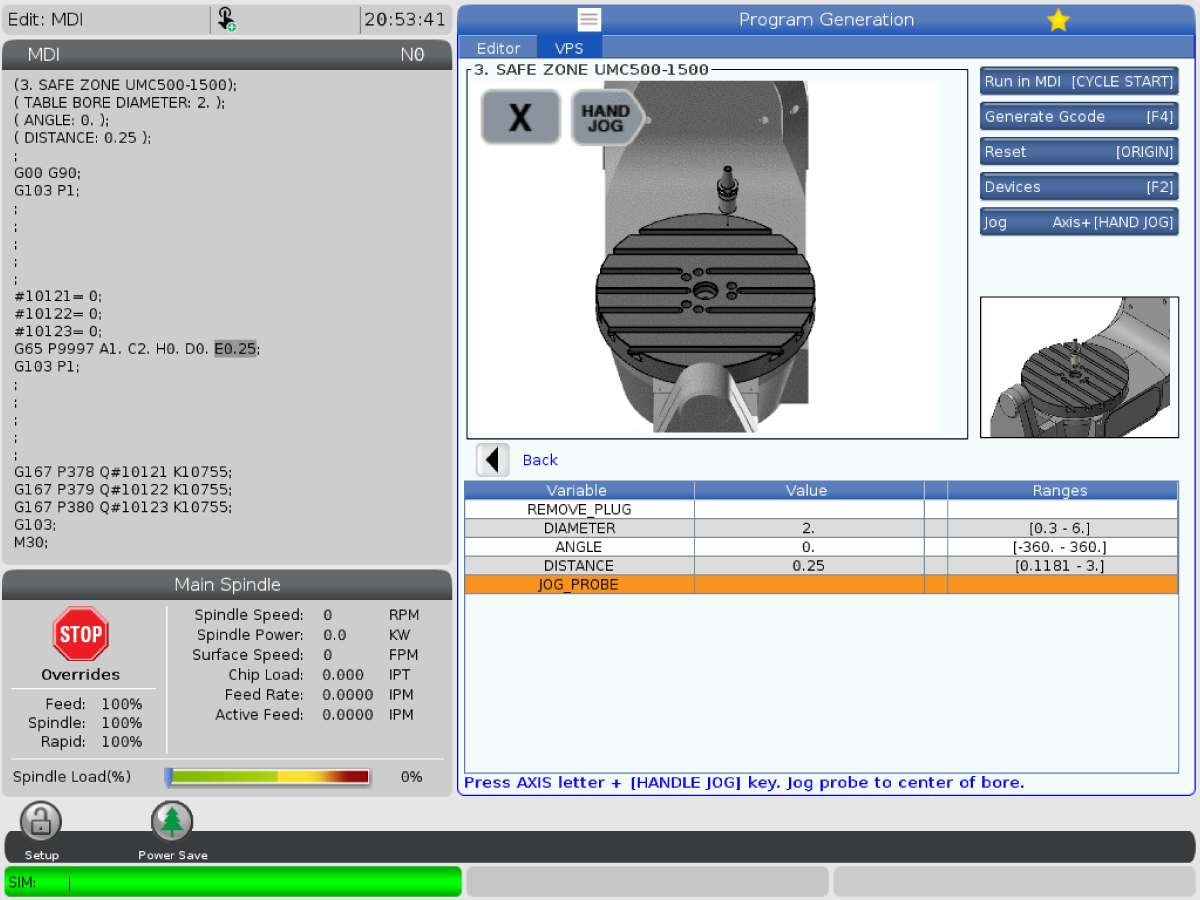
7

The final step is to jog the probe into position for calibration. This will be in the center of the bore on the platter. The VPS will instruct you to also jog the probe 0.25 in above the plane of the platter. 

Press [CYCLE START] to run the calibration or [F4] to output to MDI and review the code. 

8

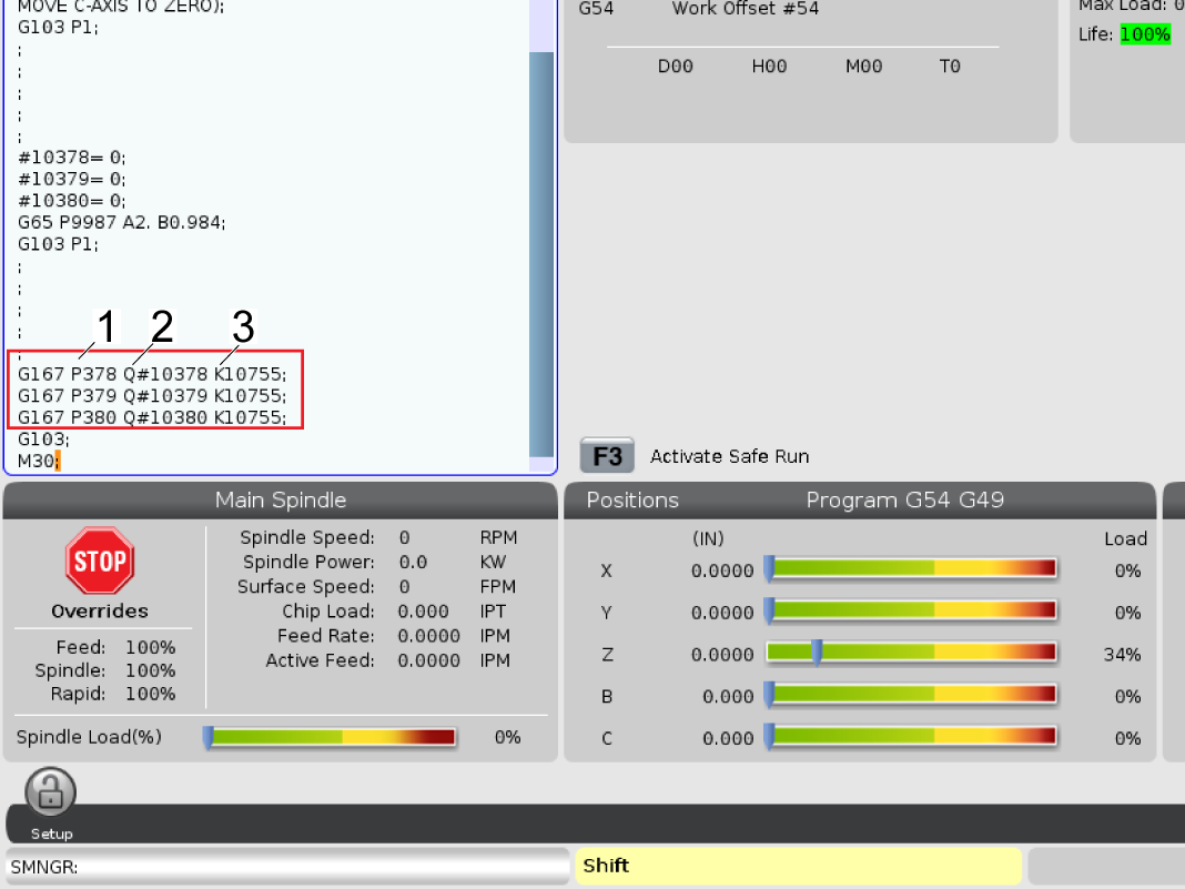
The Safe Zone program will populate the values that are found into the settings page using the code shown in the picture.

G167 provides the ability to write to settings, P code [1] is the setting number the program is writing to, Q code [2] is the value of the the Macro Variable the P code setting will be populated with, and the K code [3] essentially means it will keep these values in the setting once the program is over. 

Verify settings 378-380 are populated.

FIND DISTRIBUTOR
Feedback
Haas Logo

美元价格不包括关税、报关费用、保险费、增值税及运费。
USD prices DO NOT include customs duty, customs fees, insurance, VAT, or freight.

人民币价格包含关税、报关费用、货运保险和增值税, 但不包括运费。
CNY prices include customs duty, customs fees, insurance, and VAT. DOES NOT include freight.

Haas Delivered Price

This price includes shipping cost, export and import duties, insurance, and any other expenses incurred during shipping to a location in France agreed with you as a buyer. No other mandatory costs can be added to the delivery of a Haas CNC Product.

KEEP UP WITH THE LATEST HAAS TIPS AND TECHNOLOGY...

Sign up now!   

HAAS TOOLING ACCEPTS THE FOLLOWING:

  • Service & Support
  • Owners
  • Request Service
  • Operator Manuals
  • Haas Parts
  • Rotary Repair Request
  • Pre-Install Guides
  • Shopping Tools
  • Build & Price a New Haas
  • Available Inventory
  • The Haas Price List
  • CNCA Financing
  • About Haas
  • Careers
  • Certifications & Safety
  • Contact Us
  • History
  • Terms & Conditions
  • Haas Tooling Terms & Conditions
  • Privacy
  • Warranty
  • Haas Community
  • Haas Certification Program
  • Haas Motorsports
  • Gene Haas Foundation
  • Haas Technical Education Community
  • Events
  • Join the Conversation
  • Facebook
  • Twitter
  • Flickr
  • YouTube
  • LinkedIn
  • Instagram
  • TikTok
© 2022 Haas Automation, Inc – CNC Machine Tools

2800 Sturgis Rd., Oxnard, CA 93030 / Toll Free: 800-331-6746
Phone: 805-278-1800 / Fax: 805-278-2255

Cookie Notice

We use cookies to improve your user experience. Our Cookie Notice describes which cookies we use, why we use them, and how you can find more information about them. Please confirm you consent to us using analytics cookies. If you do not consent, you may still use our website with a reduced user experience.

Manage Settings

Cookie Notice

We use cookies to improve your user experience. Our Cookie Notice describes which cookies we use, why we use them, and how you can find more information about them. Please confirm you consent to us using analytics cookies. If you do not consent, you may still use our website with a reduced user experience.

Functional Cookies

Analytics Cookies