MyHaas Welkom,
!
Haas Tooling MyHaas/HaasConnect Aanmelden Aanmelden Haas Tooling MyHaas/HaasConnect Uitloggen Welkom, Mijn machines Laatste activiteit Mijn offertes Mijn account Mijn gebruikers Uitloggen
Zoek uw distributeur
  1. Taal selecteren
    1. English
    2. Deutsch
    3. Español - ES
    4. Español - MX
    5. Français
    6. Italiano
    7. Português
    8. Český
    9. Dansk
    10. Nederlands
    11. Magyar
    12. Polski
    13. Svenska
    14. Türkçe
    15. 中文
    16. Suomi
    17. Norsk
    18. الإنجليزية
    19. български
    20. Hrvatski
    21. Ελληνικά
    22. Română
    23. Slovenský
    24. Slovenščina
    25. 한국어
    26. 日本語
    27. Українська
  • machines Hoofdmenu
    • Verticale bewerkingscentra
      Verticale bewerkingscentra
      Verticale bewerkingscentra View All
      • Verticale bewerkingscentra
      • VF-serie
      • Universele machines
      • VR-serie
      • VP-5 prismatisch
      • Palletwisselaar VMC’s
      • Mini Mills
      • MoldMakers
      • Hogesnelheidsboorcentra
      • Boor/tap/frees-serie
      • Toolroom Mill Serie
      • Pocket Mill
      • Compact verticaal bewerkingscentrum
      • Portaalfreesmachine
      • SR-bladrouters
      • Extra grote VMC
      • Frezen met dubbele kolom
      • 3+2 positioneer-machines
    • Multi-asoplossingen
      Multi-asoplossingen
      Multi-asoplossingen View All
      • Multi-asoplossingen
      • Y-as-draaimachines
      • 5-assige freesmachines
    • Draaimachines
      Draaimachines
      Draaimachines View All
      • Draaimachines
      • ST-serie
      • Dubbele spil
      • Box Way-serie
      • Toolroom-draaimachines
      • Compacte draaimachine
      • Kamerfrees
      • Haas-staafdoorvoer
    • Horizontale freesmachines
      Horizontale freesmachines
      Horizontale freesmachines View All
      • Horizontale freesmachines
      • 50-conus
      • 40-conus
    • Draai- en indexeertafels
      Draai- en indexeertafels
      Draai- en indexeertafels View All
      • Draai- en indexeertafels
      • Draaitafels
      • Indexeertafels
      • 5-assige draaitafels
      • Extra lange draaitafels
    • Automatiseringssystemen
      Automatiseringssystemen
      Automatiseringssystemen View All
      • Automatiseringssystemen
      • Automatisering voor freesmachines
      • Draaimachine automatisering
      • Automatische werkstukbeladers
      • Automatiseringsmodellen
    • Desktop-machines
      Desktop-machines
      Desktop-machines View All
      • Desktop-machines
      • Desktop Freesmachine
      • Desktop draaimachine
      • Control Simulator, standaard
      • Control Simulator, Premium
    • Werkplaatsapparatuur
      Werkplaatsapparatuur
      Werkplaatsapparatuur View All
      • Werkplaatsapparatuur
      • Knie frees
      • Haas handbediende draaimachines
      • Haas-zaag
    • Fabricagemachines
      Fabricagemachines
      Fabricagemachines View All
      • Fabricagemachines
      • Lasersnijmachines
      • CNC-persremmen
    • SNELKOPPELINGEN Speciale serie  Speciale serie 
      EU-SERIE EU-SERIE SAMENSTELLEN EN PRIJS BEPALEN | PRIJSLIJST SAMENSTELLEN EN PRIJS BEPALEN | PRIJSLIJST Machines op voorraad Machines op voorraad WAT IS ER NIEUW WAT IS ER NIEUW UW EERSTE CNC UW EERSTE CNC
      WINKELEN VOOR GEREEDSCHAP
      • Een Haas samen stellen en de prijs bepalen
      • Prijslijst
      • Beschikbare voorraad
      • CNCA financiering
      WILT U MET IEMAND SPREKEN?

      Een Haas Factory Outlet (HFO) kan uw vragen beantwoorden en de beste mogelijkheden met u bespreken.

      CONTACT YOUR DISTRIBUTOR >
  • Opties Hoofdmenu
    • The Haas Control Waardeoptiepakketten
      Waardeoptiepakketten
      Waardeoptiepakketten View All
      • Waardeoptiepakketten
    • Product Image Spillen
      Spillen
      Spillen View All
      • Spillen
    • Product Image Gereedschapswisselaars
      Gereedschapswisselaars
      Gereedschapswisselaars View All
      • Gereedschapswisselaars
    • Product Image 4e- | 5e-as
      4e- | 5e-as
      4e- | 5e-as View All
      • 4e- | 5e-as
    • Product Image Revolvers en aangedreven gereedschappen
      Revolvers en aangedreven gereedschappen
      Revolvers en aangedreven gereedschappen View All
      • Revolvers en aangedreven gereedschappen
    • Product Image Tasten
      Tasten
      Tasten View All
      • Tasten
    • Haas beheer van spanen en koelmiddel Beheer van spanen en koelmiddel
      Beheer van spanen en koelmiddel
      Beheer van spanen en koelmiddel View All
      • Beheer van spanen en koelmiddel
    • De Haas besturing De Haas besturing
      De Haas besturing
      De Haas besturing View All
      • De Haas besturing
    • Product Image Productopties
      Productopties
      Productopties View All
      • Productopties
    • Product Image Gereedschap en opspanning
      Gereedschap en opspanning
      Gereedschap en opspanning View All
      • Gereedschap en opspanning
    • Product Image Werkstukopspanning
      Werkstukopspanning
      Werkstukopspanning View All
      • Werkstukopspanning
    • Product Image 5-assige oplossingen
      5-assige oplossingen
      5-assige oplossingen View All
      • 5-assige oplossingen
      • 5 Easy Steps to 5-Axis
    • Product Image Automatisering
      Automatisering
      Automatisering View All
      • Automatisering
    • SNELKOPPELINGEN Speciale serie  Speciale serie 
      EU-SERIE EU-SERIE SAMENSTELLEN EN PRIJS BEPALEN | PRIJSLIJST SAMENSTELLEN EN PRIJS BEPALEN | PRIJSLIJST Machines op voorraad Machines op voorraad WAT IS ER NIEUW WAT IS ER NIEUW UW EERSTE CNC UW EERSTE CNC
      WINKELEN VOOR GEREEDSCHAP
      • Een Haas samen stellen en de prijs bepalen
      • Prijslijst
      • Beschikbare voorraad
      • CNCA financiering
      WILT U MET IEMAND SPREKEN?

      Een Haas Factory Outlet (HFO) kan uw vragen beantwoorden en de beste mogelijkheden met u bespreken.

      CONTACT YOUR DISTRIBUTOR >
  • Why Haas Hoofdmenu
      Ontdek het verschil dat Haas maakt
    • Waarom Haas
    • MyHaas
    • Onderwijscommunity
    • Industrie 4.0
    • HAAS-CERTIFICERING
    • Ervaringen van klanten
  • Service Hoofdmenu
      Welkom bij Haas Service
      SERVICE HOME Bedieningshandleidingen Instructieprocedures Gidsen voor het verhelpen van storingen Preventief onderhoud Haas-onderdelen Haas Tooling Video’s
  • Video’s Hoofdmenu
  • Haas-gereedschap Hoofdmenu
MyHaas Welkom,
!
Haas Tooling MyHaas/HaasConnect Aanmelden Aanmelden Haas Tooling MyHaas/HaasConnect Uitloggen Welkom, Mijn machines Laatste activiteit Mijn offertes Mijn account Mijn gebruikers Uitloggen
Zoek uw distributeur
  1. Taal selecteren
    1. English
    2. Deutsch
    3. Español - ES
    4. Español - MX
    5. Français
    6. Italiano
    7. Português
    8. Český
    9. Dansk
    10. Nederlands
    11. Magyar
    12. Polski
    13. Svenska
    14. Türkçe
    15. 中文
    16. Suomi
    17. Norsk
    18. الإنجليزية
    19. български
    20. Hrvatski
    21. Ελληνικά
    22. Română
    23. Slovenský
    24. Slovenščina
    25. 한국어
    26. 日本語
    27. Українська
×

Resultaten zoekopdracht

Web Pages

Images

    • <
    • 1
    • >

Haas Cobot 10 (HC10) - DM/DT/UMC-350 - Installation - AD0716

Service Home Instructieprocedure Haas Cobot 10 (HC10) - DM/DT/UMC-350 - Installatie - AD0716

Haas Cobot 10 (HC10) - DM/DT/UMC-350 - Installatie - AD0716

- Spring naar sectie - Back to Top

5.3 DM/DT/MM/DC-1/UMC-350 Installatie

Recently Updated Last updated: 10/12/2023

Haas Cobot 10 (HC10) - DM/DT/MM/DC-1/UMC-350 - Installatie


AD0716

Revisie D - 11/2025

Introduction

Updated

Deze procedure laat zien hoe u de Haas 10KG Cobot (HC10) installeert.

Opmerking: De door Haas ontworpen werkcel, bestaande uit een CNC-machine en een robot, is beoordeeld op naleving van de CE-vereisten. Wijzigingen of variaties in het ontwerp van de Haas-cel moeten worden beoordeeld op naleving van de toepasselijke normen en vallen onder de verantwoordelijkheid van de gebruiker / integrator.

Machinevereisten:

  • 100.24.000.1001 versie of hoger
  • HR5.51H.16.beta.20231213.zip versie of HR6.4.9.tmp20240919.zip versie.
  • DT/DM/MM/SMM/DC-1/UMC-350 Gebouwd na datum:  (zie machinevereisten in een van beide procedures) 
    • Haas Automatische deur 
    • Haas Automatisch venster
       Opmerking: de MM/SMM, DM-3, DT-3 en DC-1 zijn alleen beschikbaar voor de optie zijlader (93-1001053).
    • Opmerking: MM/SMM-machines zonder transformator hebben een splitterkabel nodig die moet worden besteld voor achteraf geïnstalleerde cobots. De splitterkabel kan worden besteld als 93-5067.

  • 34-349xB I/O-kaart of hoger
  • 93-1000610 JOGHANDWIEL MET AFSTANDSBEDIENING TOUCH LCD (RJH-XL) JOGHANDWIEL MET AFSTANDSBEDIENING - XL  

Gereedschapsvereisten:

  • Kleine platte schroevendraaier

Fixing / Anchoring Requirements

  • The Haas 10KG Cobot (HC10) is configured and sold by Haas with a pedestal/table that is sufficiently stable when used according to Haas defined part size and weight limits. 
IMPORTANT:  For more information directly on the Hans Cobot, refer to the Hans Robot Operation Manual for Elfin Software.

There are 3 scenarios in which the cobot option can be installed on a Haas machine:

  1. Cobot option was ordered at the same time as the machine. Both the cobot and the machine are being installed together.
  2. Cobot option is ordered so that it can be installed on a previously installed machine.
  3. Cobot option was previously installed on a machine, but will now be moved to a different Haas machine.

In scenarios 2 and 3, additional parts will need to be ordered under the Serial Number of the Haas machine. See the tables below for what parts are needed in the different scenarios.

Scenario 1 - Cobot and Machine are ordered and installed together

Component Part Number Description
NO ADDITIONAL PARTS NEED TO BE ORDERED WHEN COBOT AND MACHINE ARE ORDERED TOGETHER

Scenario 2 - Cobot being field installed on existing Haas Machine

Component Part Number Description
CHECK TO SEE IF HAAS MACHINE ALREADY HAS THESE FEATURES & PARAMETERS BEFORE ORDERING
Robot Feature Unlock Parameter 93-1001031 Kit activates the robot feature on the Haas machine. To check if you need this kit, go to the Features tab on the Haas Control and check if the Robot option is highlighted. This kit does not include any physical parts.
Load Type Safety Parameters 93-1000997 Front Automation Safety Parameters - Kit is needed when the cobot will be loading parts through the front door of the Haas machine. This kit does not include any physical parts and the autodoor option would need to be purchased and installed separately.
OR  
93-1000996 Side Automation Safetly Parameters - Kit is needed when the cobot will be loading parts through the side window of the Haas machine. This kit does not include any physical parts and the autowindow option would need to be purchased and installed separately.

Scenario 3 - Cobot is being transferred from one machine to a different Haas Machine

Component Part Number Description
Cobot Integration Kit See Integration Kit Compatibility Chart Kit is needed to install parts on the Haas machine to interface with the cobot. This includes the interface box, door switches, etc... as well as the Robot Unlock Feature parameter. This kit only needs to be purchased when transferring a cobot to a new Haas machine since these parts are normally included when a cobot is ordered. 
Load Type Safety Parameters 93-1000997 Front Automation Safety Parameters - Kit is needed when the cobot will be loading parts through the front door of the Haas machine. This kit does not include any physical parts and the autodoor option would need to be purchased and installed separately.
OR  
93-1000996 Side Automation Safetly Parameters - Kit is needed when the cobot will be loading parts through the side window of the Haas machine. This kit does not include any physical parts and the autowindow option would need to be purchased and installed separately.
Safety Device 08-1899 Multi-Sided Light Curtain Kit - Kit is needed if the safety device is NOT going to be transferred from the first machine and the second Haas machine needs it's own safety device. This kit makes a 4-sided protective barrier.
OR  
08-1948 5-Sided Light Curtain Kit - Kit is needed when the safety device is NOT going to be transferred from the first machine machine and the second Haas machine needs it's own safety device. This kit makes a 5-sided protective barrier.
OR  
08-1987 Laser Area Scanner Kit - Kit is needed when the safety device is NOT going to be transferred from the first machine machine and the second Haas machine needs it's own safety device. This area scanner has a sensing distance of 4meters.

Machine Setup

1

Robot met voorlader:

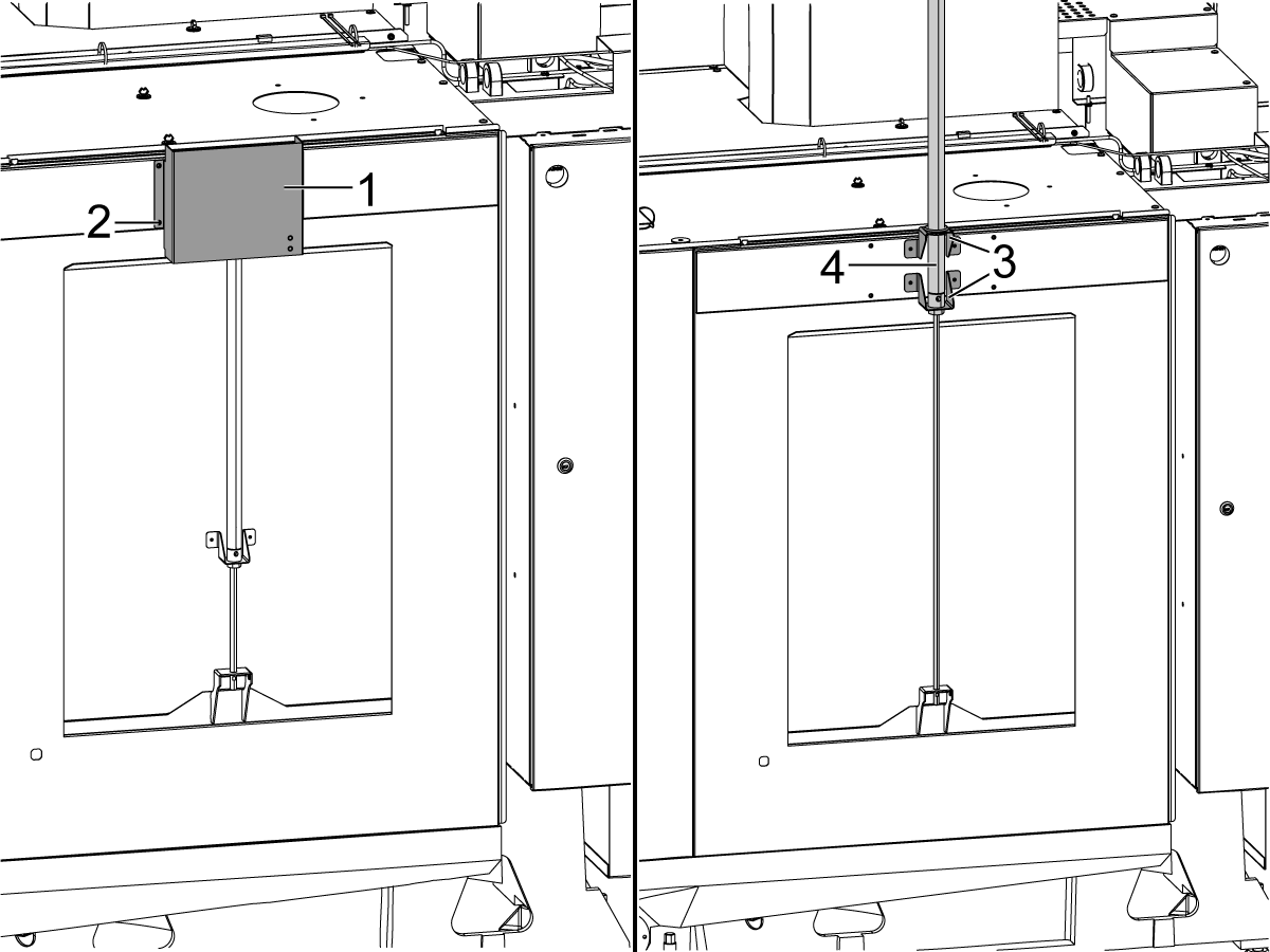
Schroef de boorgeleider [1] voor de nabijheidssensor [2] op de bovenkant van de behuizing.

Boor en tap 2x 10-32 gaten door de zijkant van de behuizing.

  • Boor maat: #21 of 5/32"
  • Tik op 10-32 NF

Verwijder de boorgeleider [1]. 

Installeer de nabijheidsschakelaar deur open [2] op deze gaten aan de zijkant van de behuizing.

Schakel de nabijheidssensor in om de gewenste locatie van de activeringsvlag [3] op de deur te vinden. Zodra de activeringsvlag [3] zich op een goede locatie bevindt om de benaderingssensor te activeren, markeert u de locatie van het gat. 

Installeer de activeringsvlag [3] met zelftappende schroeven aan de zijkant van de deur. 

Leid de kabel in de schakelkast zoals afgebeeld op de foto.

Sluit de kabel van de nabijheidsschakelaar aan op SIO PCB P27. 

2

Robot met zijlader:

Verwijder het deksel [1] en de hardware [2] om de luchtcilinder [4] van het Automatische venster bloot te leggen. Til de luchtcilinder [4] omhoog zodat de beugels [3] en de luchtcilinder zijn bevestigd zoals afgebeeld.

Sluit de meegeleverde grijze en gele luchtleidingen aan op het luchtcilinder van het Automatische Venster. De poorten op de luchtcilinder hebben grijze en gele kabelbinders om aan te geven waar de leidingen op elkaar aansluiten.

Plaats de afdekking [2] over de luchtcilinder van het Automatische venster.

3

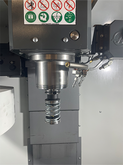
  • De veer-duwstang is gemaakt met een schacht om op een 25 mm of 1 inch gereedschapshouder te passen
  • Dit gereedschap moet een gereedschapshouder in de gereedschapscarrousel opnemen.
  • Programmeer de volgende stappen aan het begin van elk  programma om ervoor te zorgen dat het werkstuk goed in de klem zit:
    • Vind de veer-duwstang boven het werkstuk
    • Verplaats de Z-as om de veer ongeveer 0,50 inch of 12,7 mm samen te drukken
    • Open de gereedschapsklem met een vertraging van één seconde
    • Sluit de gereedschapsklem met een vertraging van één seconde

Opmerking: Het artikelnummer voor de veerduwstang is: 

  • 30-12642 VEERDUWSTANG.  De houder van 25 mm of 1,0 inch wordt apart verkocht.

Cobot Installation

1

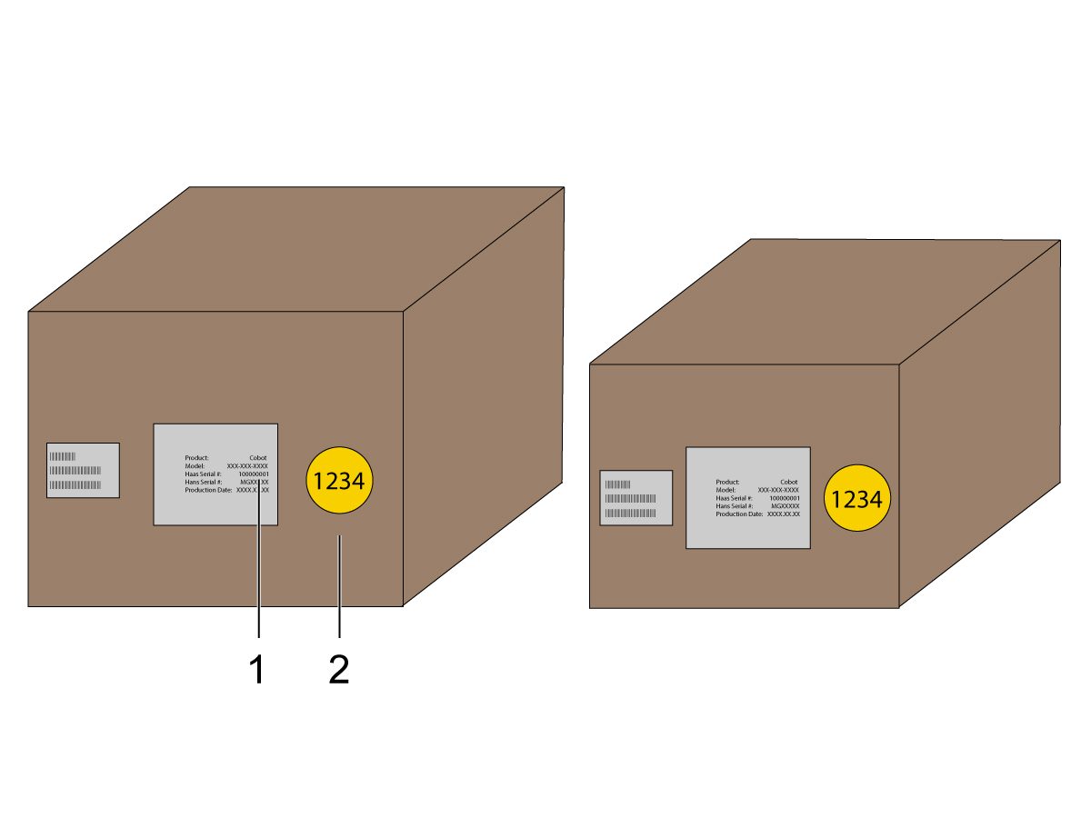
Controleer of de cobot en zijn besturingskast van dezelfde overeenkomende set met overeenkomende serienummers zijn.

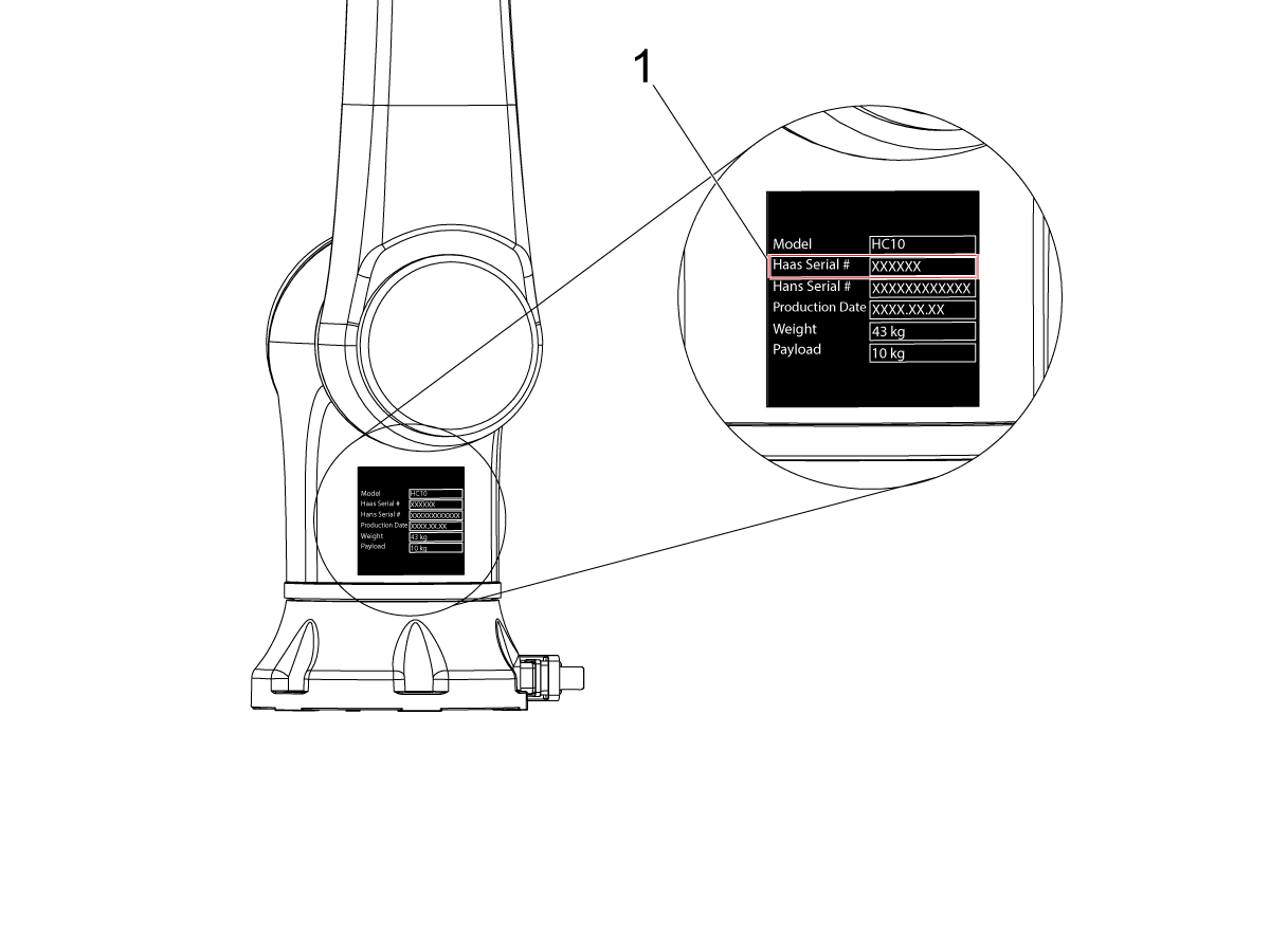
Er is een witte sticker met het serienummer van Haas [1]. Zorg ervoor dat deze op beide dozen hetzelfde zijn.

Er is een gele cirkel sticker met een identificatienummer [2]. Zorg ervoor dat deze op beide dozen hetzelfde zijn.

2

Meet deze afmetingen vanaf de machineschort tot aan de zijkant van het voetstuk.

  De volgende afmetingen zijn aanbevolen afstanden. De positie kan afhankelijk van de gebruikerstoepassing variëren. Raadpleeg de volgende stappen voor de positionering op de cobot en de onderdelentafel voor cobots met voorlader of zijlader.

Aanbevolen wordt om de Haas Cobot 10 te combineren met het Haas Cobot voetstuk. Deze sokkel is zo geconfigureerd dat hij voldoende stabiel is bij gebruik volgens de door Haas gedefinieerde limieten voor productgrootte en gewicht.

3

Laden aan de voorkant:

Plaats het voetstuk en de werkstuktafel op de volgende locatie ten opzichte van de machine:

Afmeting Imperial (inch) Metrisch (cm)
Voorkant van de machine naar de voorkant van het voetstuk [1] 13 inch 33 cm
Links van de machine naar de linkerkant van het voetstuk [2] 24 inch 61 cm
Voorkant van de machine naar de hoek linkervoor van de werkstuktafel [3] 8 inch 20,3 cm
Voorkant van de machine naar de hoek rechtsvoor van de werkstuktafel [4] 42,25 inch 107 cm
Links van de machine naar de hoek linksvoor van de werkstuktafel [5] 6,25 inch 15,9 cm

4

Laden aan de zijkant:

Plaats het voetstuk en de werkstuktafel op de volgende locatie ten opzichte van de machine:

Afmeting Imperial (inch) Metrisch (cm)
Voorkant van de machine naar de linkerkant van het voetstuk [1] 21 inch 53,4 cm
Rechts van de machine naar de voorkant van het voetstuk [2] 13 inch 33 cm
Voorkant van de machine naar de linkerkant van de werkstuktafel [3] 3 inch 7,6 cm
Rechts van de machine naar de voorkant van de werkstuktafel [4] 27 inch 68,6 cm

5

Veranker het voetstuk in de grond. Nivelleer het voetstuk met een waterpas.

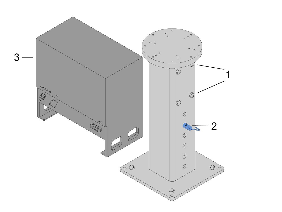
Stel de gewenste hoogte in door de stelschroeven [1] los te draaien en vervolgens de gaffel-pen [2] aan te passen. Draai de stelschroeven [1] weer vast voordat u de robot installeert. Plaats een waterpas op de bovenkant van het voetstuk terwijl u de (x4) zeskantbouten aan de basis gebruikt om het niveau in het X- en Y-vlak in te stellen.

Plaats de cobotbesturingskast [3] direct naast het voetstuk om voldoende speling voor de kabels te garanderen. 

Opmerking: De lay-outs in de vorige stappen hebben een voetstukhoogte van 24 inch (61 cm).

6

Verwijder de robot uit de verzenddoos. 

 LET OP: Installeer de adapterplaat tussen het voetstuk en de robot indien nodig. 

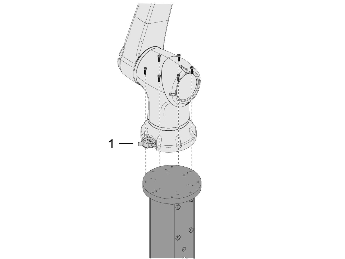
Installeer de cobot bovenop het voetstuk.

 OPMERKING: Zorg ervoor dat de cobotkabelconnector [1] haaks staat met de voorkant van de machine. 

BELANGRIJK: De cobot weegt ongeveer 40 lbs en moet worden opgetild met een apparaat dat dat gewicht veilig kan optillen.

Verwijder de robotlifthardware na het installeren van de robot.

7

In de verpakking van de cobot zit een kleine zak [1] gevuld met reserveonderdelen, inclusief: 

  • Zekering
  • Schroeven (x2)
  • Toetsen besturingskast

Er is een medium zak [2] gevuld met een extra M12-connector. Deze kabel kan worden gebruikt om in- en uitgangen voor de eind-I/O-module te configureren. 

Er is een grote zak [3] gevuld met papier en een USB-stick gedownload met de cobotsoftware.

Zorg ervoor dat u deze reserveonderdelen ergens veilig bewaard voor toekomstig gebruik. 

Robot Electrical & Air - Installation

 DANGER: Working with the electrical services required for CNC machines is extremely hazardous and can result in serious injury or death.

Before connecting line wires to the CNC:

  • Turn off all power to the machine at the source.
  • Perform a Lockout-Tagout (LOTO) procedure to ensure the power remains off during service.
  • Verify that power has been disconnected by using an AC voltage detector on all incoming lines.

If you are uncertain about how to safely disconnect power or perform LOTO procedures:

  • Do not proceed.
  • Contact qualified personnel or obtain appropriate assistance before continuing.

Failure to follow these precautions may result in electrical shock, equipment damage, or fatal injury.

 Danger: Before beginning any work inside the control cabinet, verify that the High Voltage indicator light on the 320V Power Supply / Vector Drive has been off for a minimum of five (5) minutes. This waiting period ensures that residual voltage has dissipated and reduces the risk of electric shock.

Certain service procedures involve high-risk electrical components and may pose serious injury or fatality hazards. Technicians must not attempt any procedure unless they have a complete understanding of the steps involved and the associated risks.

If there is any uncertainty regarding a procedure, contact your Haas Factory Outlet (HFO) to arrange for a qualified service technician.

1

Connect Interface Box to Haas Machine:

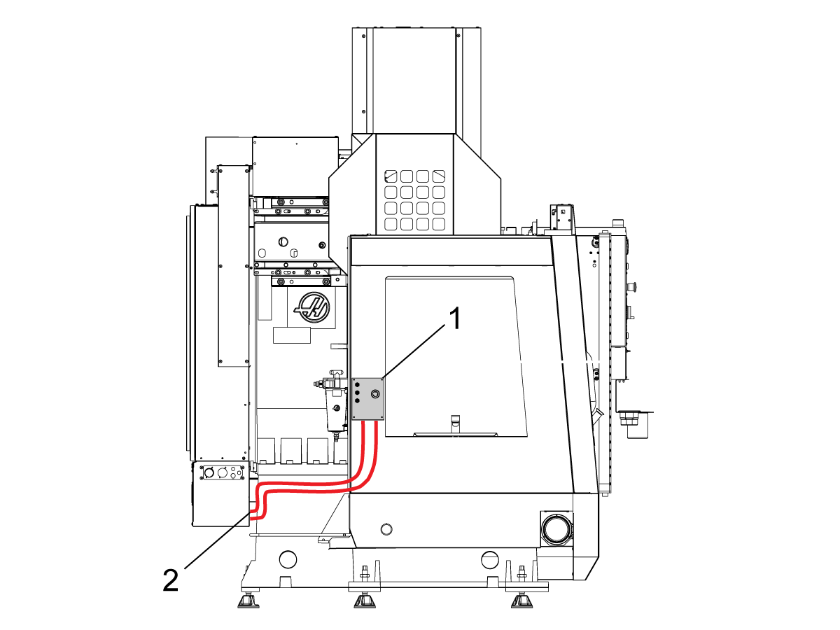
The robot safety devices interface box 32-9018 has magnetic mounts to attach to the machine sheet metal. Mount the interface box [1] as shown in the picture.

Route the interface electrical cables [2] along the enclosure with the magnetic mounts and zipties. Route the cable through the bottom of the electrical cabinet.

NOTE: For information on upgrading the interface box to the Robot Safety Devices Interface Box, refer to the Robot Safety Devices Interface Box - Installation - AD0703. 

2

Connect Interface Box to Haas Control Cabinet:

Connect cable 33-8562C E-STOP terminal block to TB-1B [1] and connect the Setup mode terminal block to TB-3B [1] on the SIO PCB.  

Plug the user relay into K9 and K10 [2].

Verify the jumper is installed on the SIO PCB at JP1.

Connect the pigtail cable labeled P1 SIO to the SIO PCB at P1 [3]

NOTE: If the machine has a Regen Vector Drive, unplug cable 33-0634 FILTER OV TO IOPCB P1 from P1 SIO and plug it into the connector FILTER OV FAULT on cable 33-8562C. If the machine does not have a Regen Vector Drive, do not plug anything into the connector FILTER OV FAULT.

Connect the RJ-45 cable [4] to Ethernet to USB adapter [5] (33-0636).  Connect the USB connector end to the Maincon PCB J8 top port. Add a ferrite filter [6] to the USB adapter.

Mount the 24VDC Power Supply [7] to the left side of the control cabinet and plug into connector labeled 24V PS on cable 33-8562C. Connect cable 33-1281 [8] to the 24VDC Power Supply [7] and plug into P3 on the PSUP PCB. 

3

For MM/SMM CM/CL machines Without XMR

If P3 is occupied by a jumper connected from P3 [10] to P7 [9] on the PSUP PCB, a splitter cable is needed to allow the 24VDC power supply [7] to be connected to the 120VAC connectors on the PSUP. Connect the male connector of the splitter cable to P3 [10] and then connect the jumper from that cable to P7 [9] and also cable 33-1281 [8].

Note: Make sure that the jumper cable is connected where the red lines up with the red from the splitter cable.

4

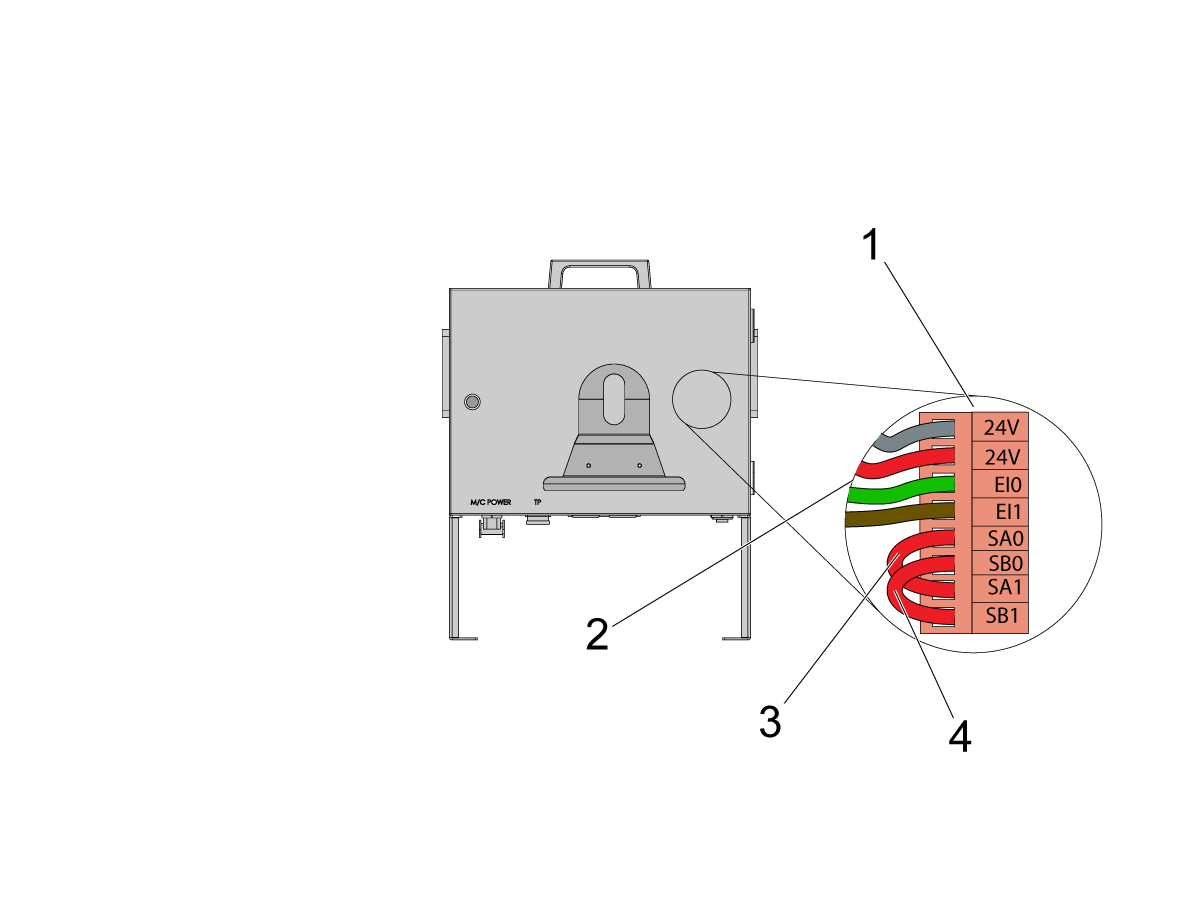
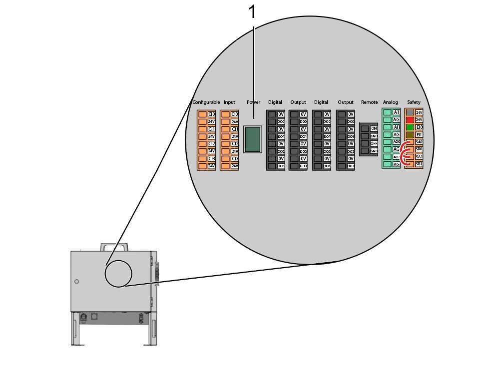
Inside the Cobot control box, install part of the robot signals cable (33-1272 or 33-1351).  To do so, remove the safety connector [1] from the Cobot control box in order to install the different colored wires into their respective location

33-1272 / 33-1351 cables [2] going to safety connector:

  • Gray wire to top 24V
  • Red wire to bottom 24V
  • Green wire to EI0
  • Brown wire to EI1
  • Jumper [3] from SA0 to SA1
  • Jumper  [4] from SB0 to SB1

 NOTE: The rest of the wires from this cable are not used. Put some electrical tape on each wire lead and Ziptie the leftover unused wires. 

5

Important: After installing all the cables from the robot signal cable, make sure that the fuse [1] remains installed at all times to protect the Cobot control box.

6

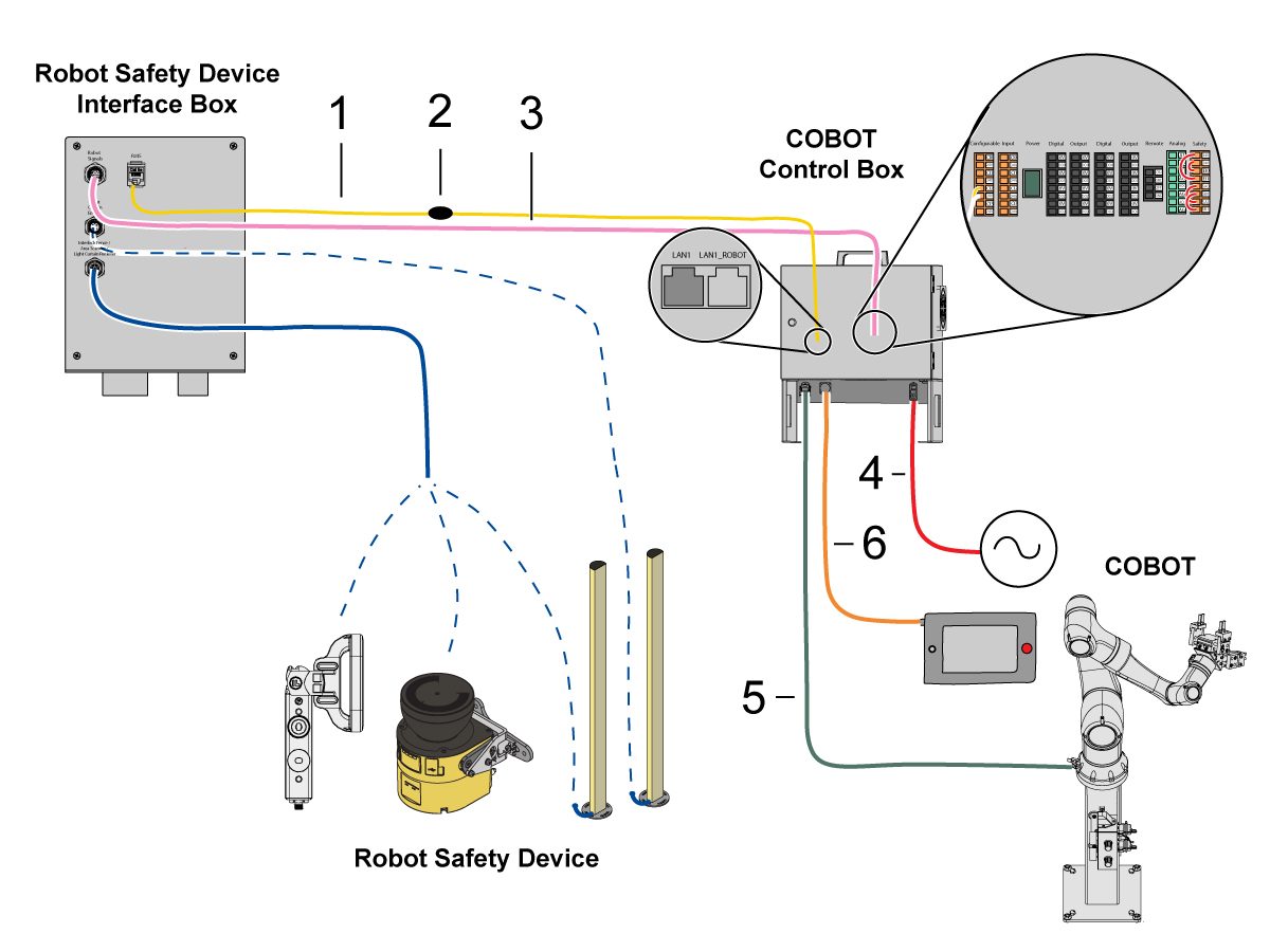
Connect Cobot to the Interface Box:

Connect the RJ45 ethernet cable [1] from the Cobot Control Box to the interface box. Add a ferrite filter [2] to the RJ-45 cable.

Connect the robot signals cable [3] from the Cobot Control Box to the interface box. 

Connect the 120 VAC Cobot Power Cable [4] to the external power source. 

Connect the robot power cable [5] from the control box to the Cobot.

Connect the teach pendant cable [6] from the control box to the teach pendant. 

NOTE: For more information regarding interlock fence, area scanner or light curtain installation, refer to the Robot Safety Device section below.

7

Make sure the Remote Jog Handle is installed onto the machine.

NOTE: For more information on the RJH-XL installation, refer to Remote Job Handle - Touch Large (RJH-XL) - Installation - AD0533. 

8

Steps 7 thru 10 are wiring and hose routing instructions for the pneumatic grippers. Refer to the grippers installation section lower on this page for the mechanical installation.

Install the dual air solenoid assembly on to the side of the pedestal while giving the airlines enough slack. Make sure it's in a position where it will not be in the way. Route the airline [1] under the machine back towards the CALM cabinet as shown.

9

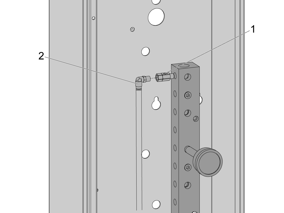
Inside the CALM cabinet, remove a plug from one of the CALM manifold ports and install the check valve [1] (58-1863) onto the port's fitting. Route the input airline [2] from the dual air solenoid assembly (from previous step) into the CALM cabinet and connect the airline to the check valve.

Turn the machine air supply ON.

10

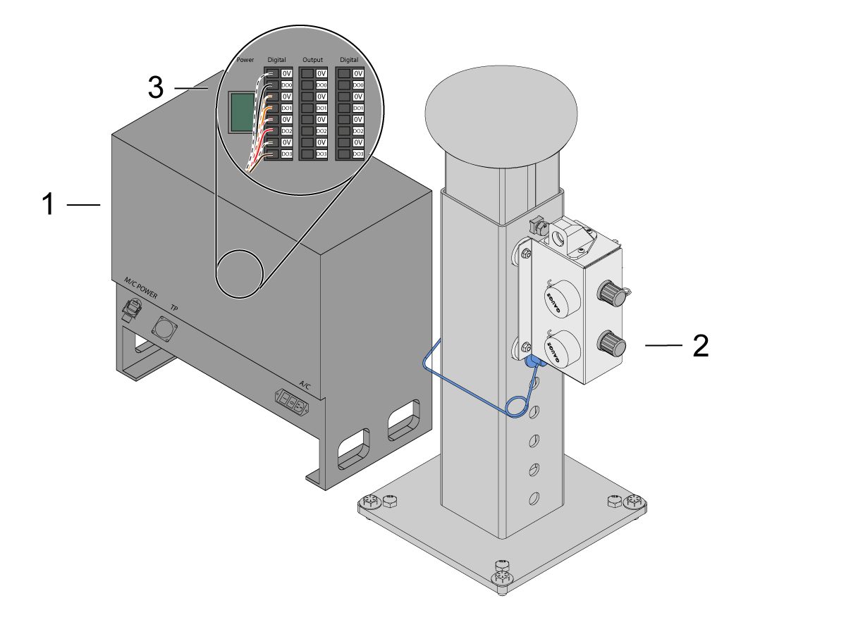
Make sure to power OFF the control box [1].

Connect the solenoid cable from the dual air solenoid assembly [2] into the Digital Output on the Cobot control box [1]. Remove the connector from Cobot control box.

11

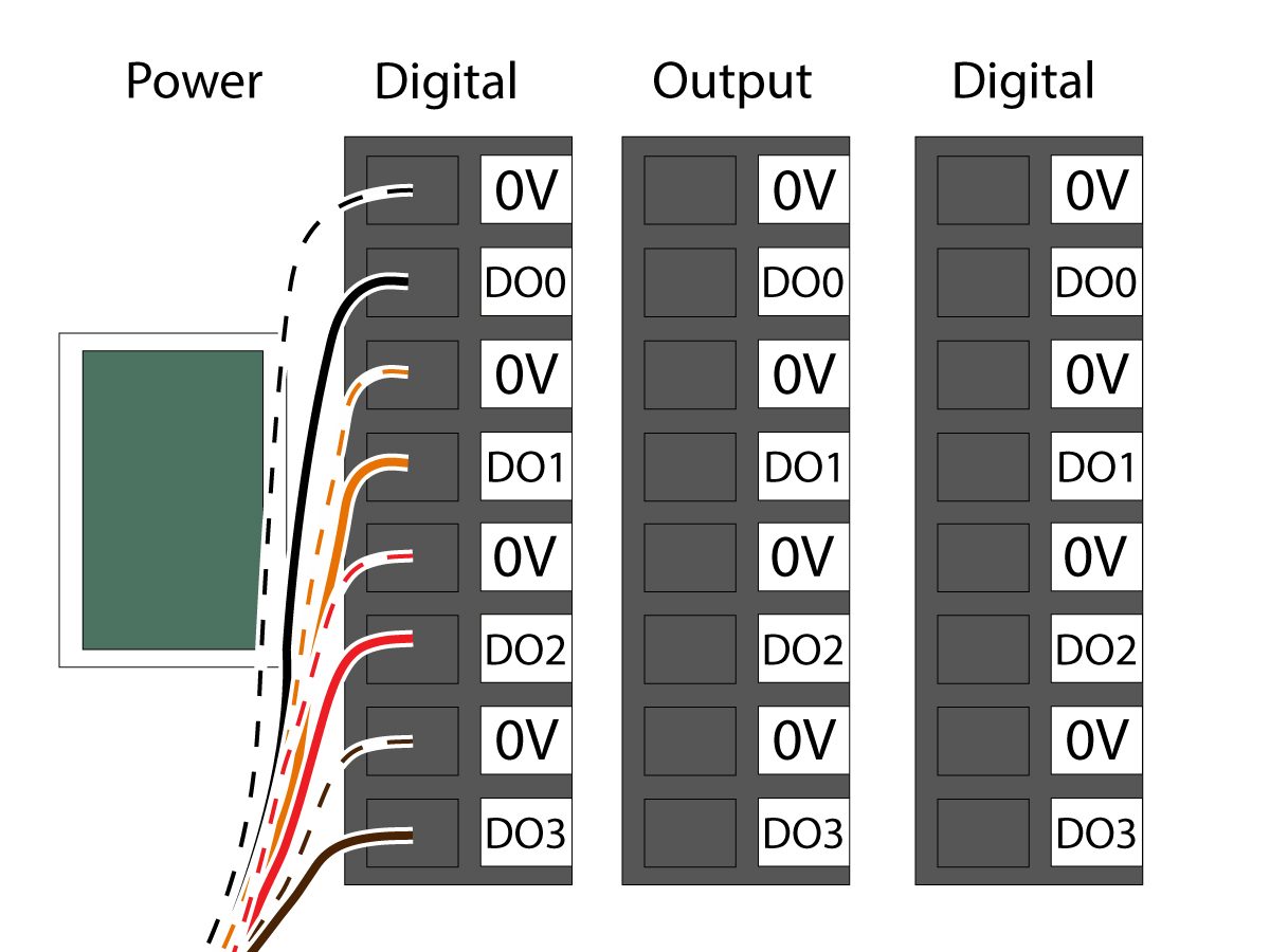
Connect the gripper solenoid power cable (33-1276 / 33-1341) to the Digital Output terminal inside the control box. Install the different colored wires into their respective location:

  • Black/white cable into 0V
  • Black cable into DO0
  • Orange/white cable into 0V
  • Orange cable into DO1
  • Red/white cable into 0V
  • Red cable into DO2
  • Brown/white cable into 0V
  • Brown cable into DO3

Power ON the control box.

Robot Safety Device

BELANGRIJK: BEDIEN DE ROBOT NIET TOTDAT U DE WERKING VAN DE VEILIGHEIDSINRICHTING CORRECT HEBT GECONFIGUREERD EN GETEST.

Lichtgordijn:

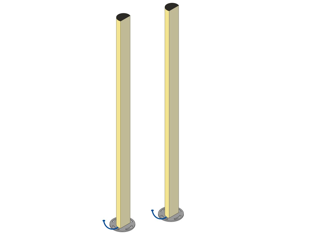
Cobot-verpakkingen worden geleverd met de lichtgordijnzender en -ontvanger als standaard veiligheidsvoorziening. Volg de onderstaande procedure voor installatie van het lichtgordijn: 

Installatie lichtgordijn

OPMERKING: Als de gebiedsscanner of de HC10 Machine Ready-set is besteld, is er ook een 1M lichtgordijnontvanger en zender. Deze worden geleverd met alle cobots. 

Robothek:

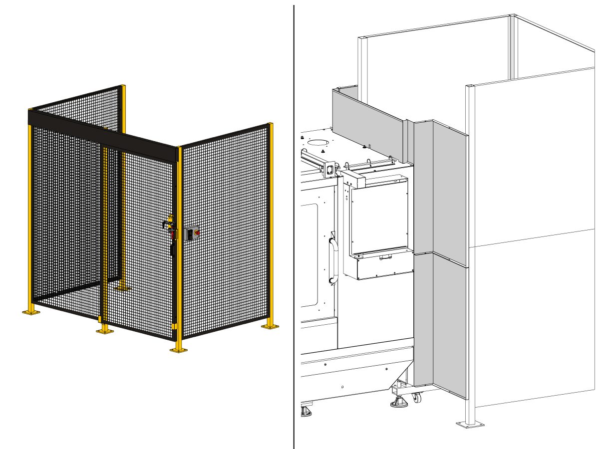
Als de machine is uitgerust met de hek-optie, moeten het robothek en de deurvergrendeling op de machine worden geïnstalleerd. Volg de onderstaande procedure voor installatie:

Installatie robotafrastering

Nadat het hek is geïnstalleerd, installeert u het hekpaneel tussen de machine en het robothek, beginnend met het paneel dat eerst aan de bovenkant van de machine wordt bevestigd.

Opmerking: De plaatwerken wandpanelen die het hek verbinden met de machinebehuizing moeten worden geïnstalleerd met de meegeleverde zelftappende schroeven en zullen niet in lijn liggen met de gaten.

Gebiedsscanner: 

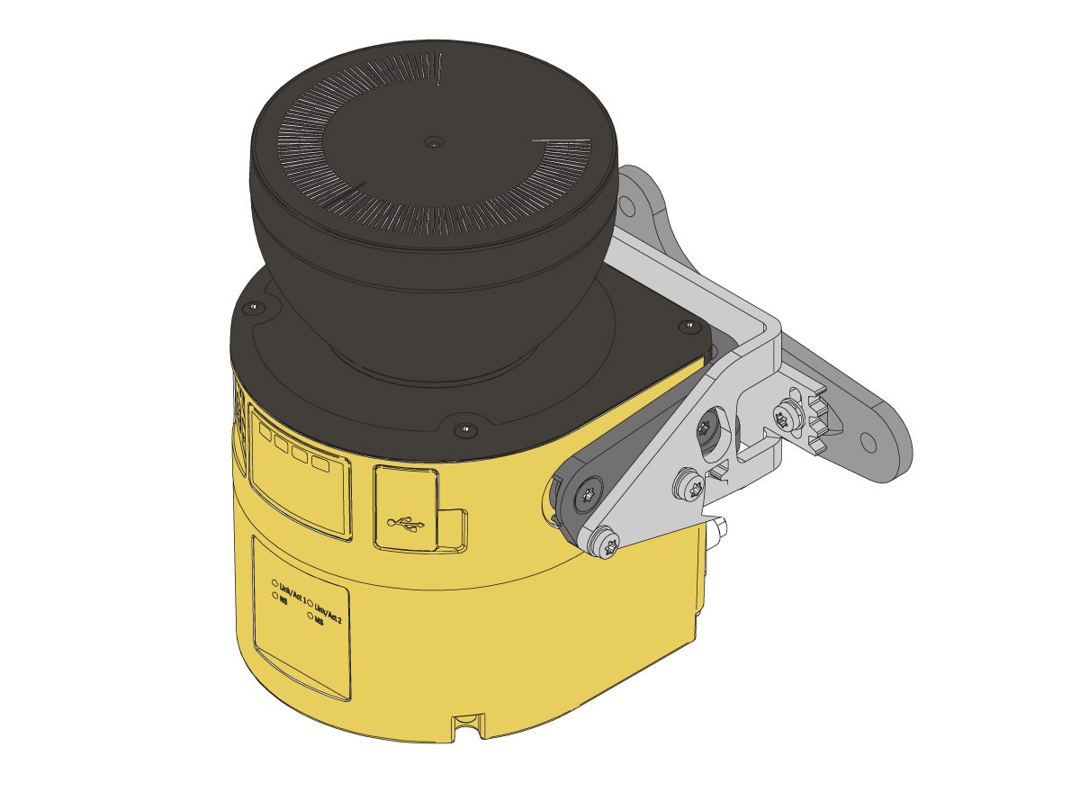
Als de machine is uitgerust met de optie gebiedsscanner, moet de gebiedsscanner worden geïnstalleerd en geconfigureerd voor de ruimte. Volg de onderstaande procedure voor installatie: 

Installatie van de gebiedsscanner

First Power-UP

1

Zet de Haas-machine op ON. 

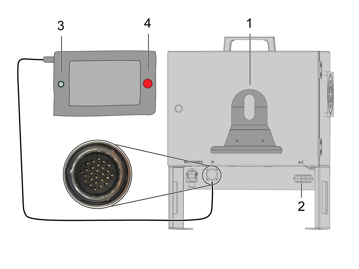
Schakel de cobot in door de aan/uit-schakelaar [1] om te draaien.

Zet de Cobot teach-paneel op ON door op de cirkel [2] te drukken. 

Zorg ervoor dat E-STOP [3] op het Cobot teach-paneel is uitgeschakeld. 

Om de taal te wijzigen, klikt u op het taalkeuzemenu. Kies EN voor Engels. Om deze wijziging van de instelling te bevestigen, zal het cobot-teachpaneel een pop-up hebben met de vraag om de gebruikersnaam en het wachtwoord in te wisselplaat. 

Voer "admin" in voor zowel de gebruikersnaam als het wachtwoord. 

2

Opmerking: Het cobot-teachpaneel heeft een pop-up met de vraag om de gebruikersnaam en het wachtwoord in te wisselplaat. Om in te loggen op de teach-paneel gebruikt u deze inloggegevens:

  • Gebruikersnaam = admin
  • Wachtwoord = admin

Ga naar de Run (Uitvoer)-modus. Druk op Inschakelen. 

Ga naar de Jog-modus [1].

Verplaats elke verbinding naar zijn nullocatie met de knoppen Nul verplaatsen [2]. 

3

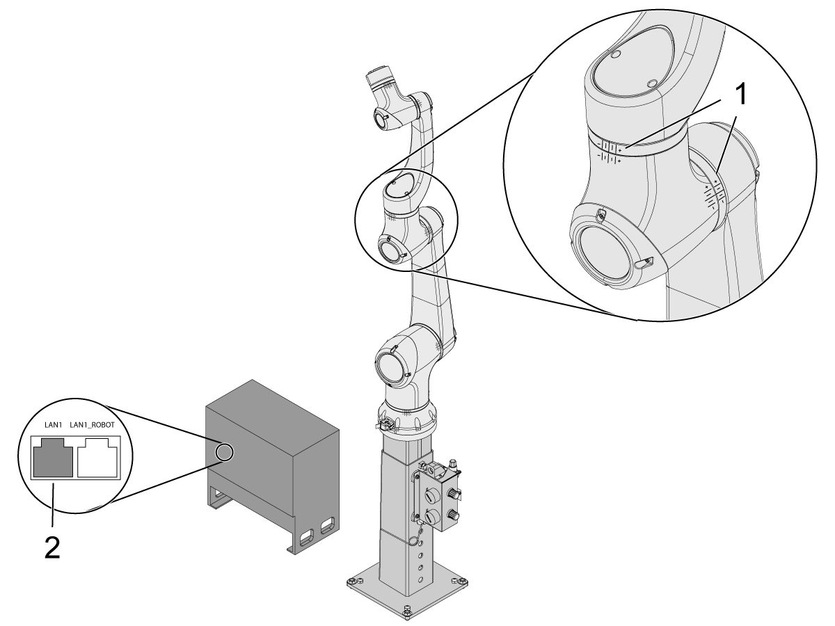
Zodra de robot zich op zijn nullocatie bevindt, controleert u of de hash-lijnen [1] zijn uitgelijnd aan weerszijden van elk gewricht op de cobot. 

 BELANGRIJK: Als eventuele hash-lijnen [1] niet zijn uitgelijnd, jog het specifieke gewricht dienovereenkomstig totdat alle hash-lijnen [1] zijn uitgelijnd. Deze positie wordt in de volgende stap ingesteld als de nieuwe nulpositie van de cobot.  

Sluit een ethernetkabel [2] van de cobotbesturingskast aan op een computer.

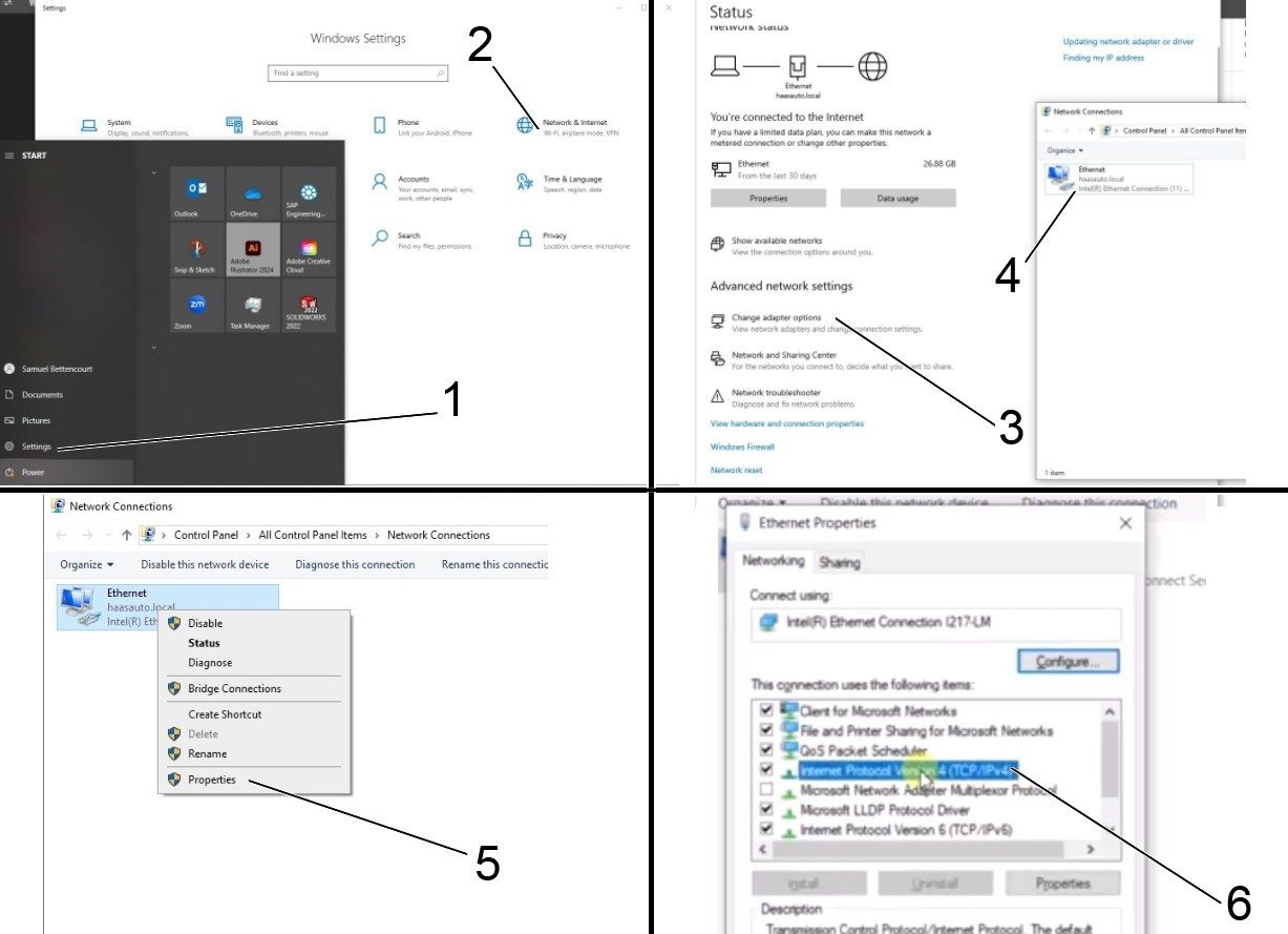
Wijzig op de computer de adapterinstelling om de ethernetpoort in te schakelen. 

Opmerking: Zie de volgende stappen voor hulp bij het wijzigen van de adapterinstellingen.

4

Als u de adapterinstellingen wilt wijzigen, opent u de instellingenpagina [1] op de computer en klikt u vervolgens op Netwerk & Internet [2] waarmee de netwerkstatuspagina wordt weergegeven.

Klik op Adapteropties wijzigen [3] en klik vervolgens met de rechtermuisknop op Ethernet [4] en open het venster Eigenschappen [5]. Selecteer van daaruit de optie Internet Protocol versie 4 (TCP/IPv4) [6] en klik op OK . 


5

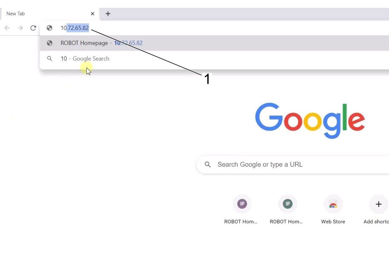
De ethernet-instellingen zijn nu correct. Open een webbrowservenster en typ het IP-adres van de cobot[1]. 

Opmerking: Dit is hetzelfde proces als bij het aansluiten van een laptop op een HRP-1/2/3. Voor meer informatie over het verbinden met de cobot via ethernet, raadpleegt u de video op de HRP-Troubleshooting -pagina die zich in het gedeelte Connect en Jog Haas Robot bevindt. 

6

Download HRTool via HBC. Navigeer in het servicegedeelte van HBC naar Utilities (Hulpprogramma's) > Documents en Software (Documenten en software) > 01 Control Software (Besturingssoftware) > 01 Next Generation Control (Besturing van de volgende generatie)> 10 Cobot Software (Cobotsoftware) > HRTool.zip.

Pak de map uit en navigeer naar HRToolsMaind.exe.

Voer het IP-adres van de cobot in dat u onder het tabblad Systems (Systemen) vindt.  Klik op Instelling. 

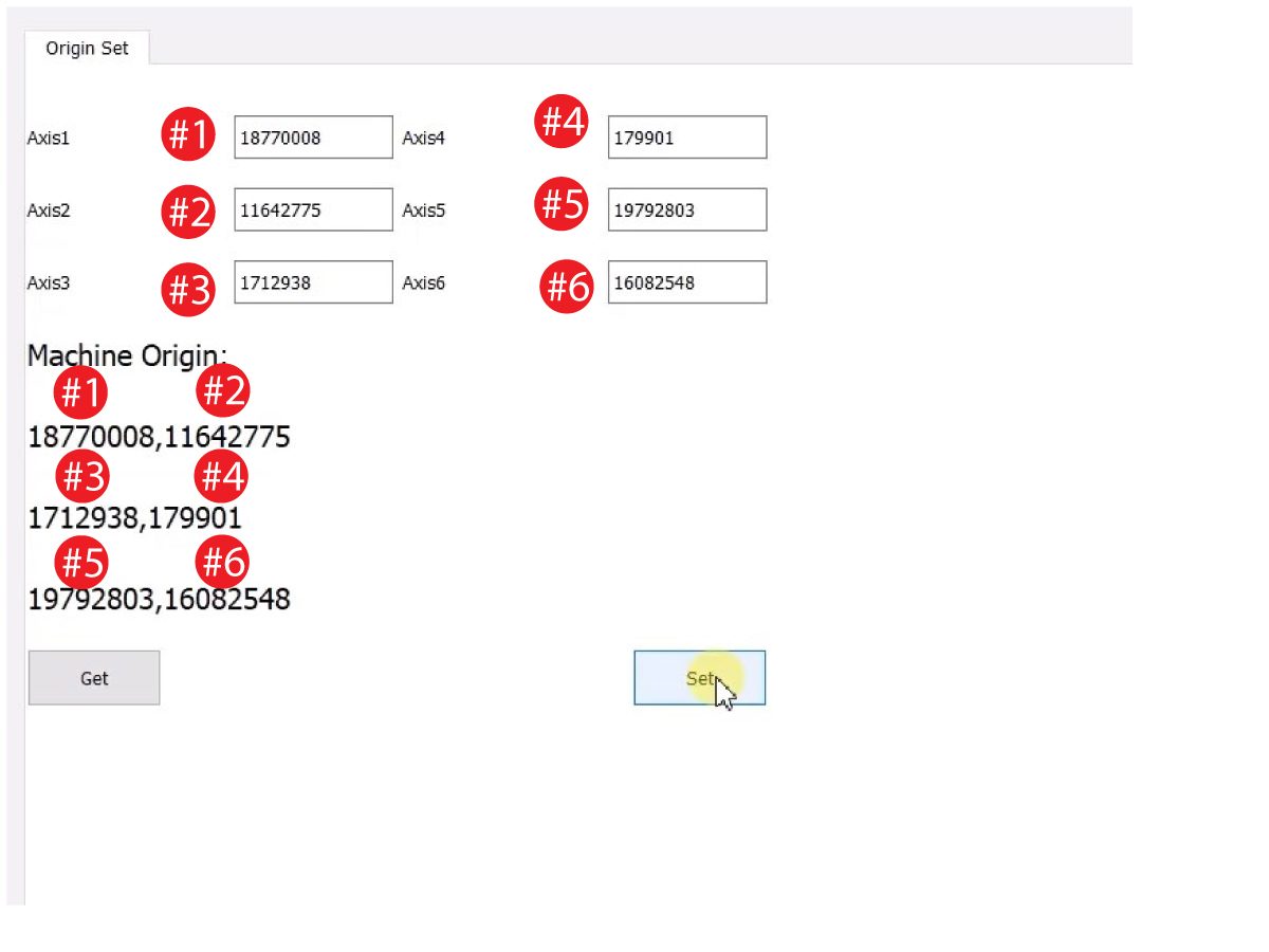
Ga naar het tabblad Config (Configuratie) op HRTool.

Klik op "get" (verkrijgen) om de werkelijke versus theoretische encoderwaarden te zien. 

Klik op "set" (instellen) om de theoretische waarde in te stellen op de werkelijke encoderwaarden. Deze stap stelt de huidige positie van de cobot in als zijn nieuwe uitgangspositie. 

7

Zorg ervoor dat de werkelijke en theoretische encoderwaarden van elk gewricht overeenkomen. 

OPMERKING: Als de waarden niet overeenkomen, druk dan opnieuw op "Set" (Instellen). 

8

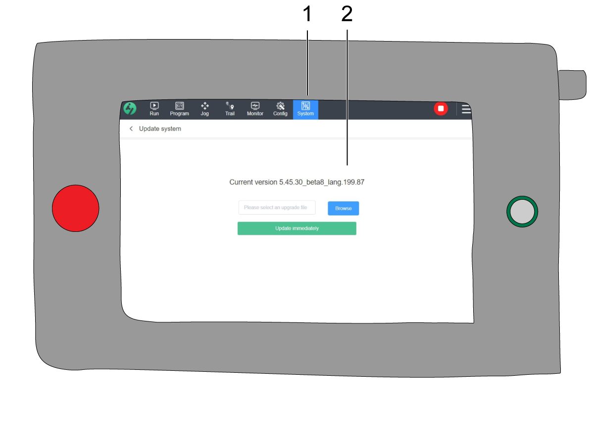
Navigeer op het teach-paneel naar System (Systeem) [1] en vervolgens naar Update System (Systeem bijwerken). 

Controleer of de Cobot-firmware [2] ofwel:

  • HR5.51H.16.beta.20231213.zip
  • HR6.4.9.tmp.20240919.zip

OPMERKING: Firmwareversie HR6.4.9.tmp.20240919.zip is compatibel met cobots van elke grootte.

Raadpleeg de sectie Haas Cobot - Onderhoud voor de firmware-updateprocedure. 

9

Schakel de Haas CNC in.

Laat alle assen teruglopen naar het nulpunt.

Plaats de service-USB-sleutel.  Ga in Onderhoudsmodus.

Ga naar Parameters> Fabriek tabblad.  Verander het volgende:

  • 1278 [1278:] Robot gereed Noodstop ingeschakeld op WAAR
  • 2191 [694:] LICHTGORDIJN TYPE naar LC_TYPE_1
  • 2194 [:] Schakelaar voordeur volledig open inschakelen naar WAAR

Notitie: Machines met softwareversie 100.20.000.1010 of hoger moet de volgende parameter wijzigen:

  • 2192 [:] Activeerder drempel lichtgordijn naar 0

Druk op [SETTING].

Stel de instellingen in:

  • 372 werstuk lader type naar 3: Robot.
  • 376 Lichtgordijn ingeschakeld naar Aan


10

Druk op het Haas-paneel op [CURRENT COMMANDS].

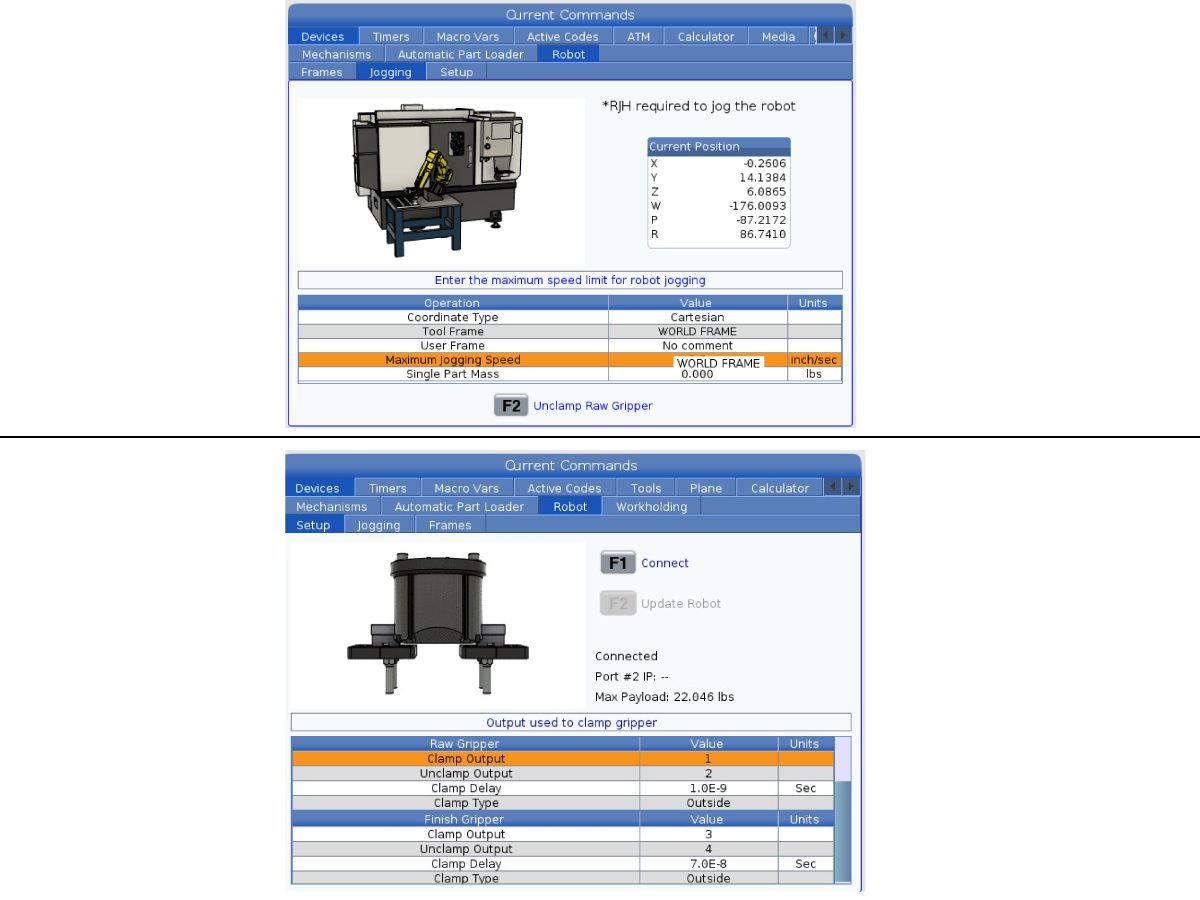
Ga naar de tab Apparaten>Robot>Joggen . Verander het volgende:

  • Maximale joggingsnelheid naar 7,9 inch/sec

 Opmerking: de joggingstappen op de RJH zijn een percentage van deze maximumsnelheid. Om de afstand die de robot aflegt bij elke jogwielklik te verkleinen, moet de maximale jogsnelheid naar een lagere waarde worden gewijzigd.

Ga naar het Opstelling tabblad. Verander het volgende:

  • Maximale robotsnelheid tot 118 in/sec (2000 mm/sec). 
  • Voer de Netto massa van de grijper in. Raadpleeg de lay-outtekeningen op onze website (Enkele grijper lay-outtekening OF Dubbele grijper lay-outtekening) om de juiste waarde voor deze instelling te krijgen

WAARSCHUWING: Als deze waarde verkeerd wordt ingesteld, kan dit ertoe leiden dat de robotarm niet correct beweegt. 

 
  • Aantal grijpers naar het aantal grijpers.
  • Grijper onbewerkte stukken klemmen uitgang naar 1.
  • Uitgang ontspannen grijper onbewerkte stukken op 2.
  • Grijper onbewerkte stukken Klemvertraging tot de duur van vastklemmen/ontspannen in sec.
  • Grijper onbewerkte stukken klemtype naar OD/ID kaart.
  • Uitgang klemmen nafreesgrijper op 3.
  • Uitgang ontspannen nafreesgrijper op 4.
  • Nafreesgrijper vertraging klem tot de duur van vastklemmen/ontspannnen in sec.
  • Grijper onbewerkte stukken klemtype naar OD/ID kaart.

Security Risk Level

1

IMPORTANT: Make sure to perform an appropriate risk-assessment and met all appropriate safety requirements. 

2

Based off the risk assessment, set the appropriate security risk level on the Cobot teach pendant. Navigate to Config > General Restrictions and tap of the desired security risk level [1] from 0 - 5.

Use the  "admin" code in the safety verification to change the security level.

NOTE: When the security risk level is lower, the robot will have a lower maximum speed, force, etc. When the security risk level is higher, the robot will have a higher maximum speed, force, etc. 

This security risk level will calculate the maximum allowable force, speed, power, momentum, elbow speed and elbow force [2] that the Cobot will withstand before Alarm 9150.10017 Collison Stop Error is triggered. 

IMPORTANT: The robot's programmed speed cannot be greater than the allowable speed from the security risk level. 

NOTE: For more information regarding alarms, refer to the Haas Cobot - Troubleshooting Guide. 

Activation

1

Download and load the configuration files by logging into the HAAS SERVICE PORTAL.

Download the safety automation option front/side configuration files.

Load the option configuration patch file to the control. Refer to the NEXT GENERATION CONTROL - CONFIGURATION FILE - DOWNLOAD/LOAD procedure.

2

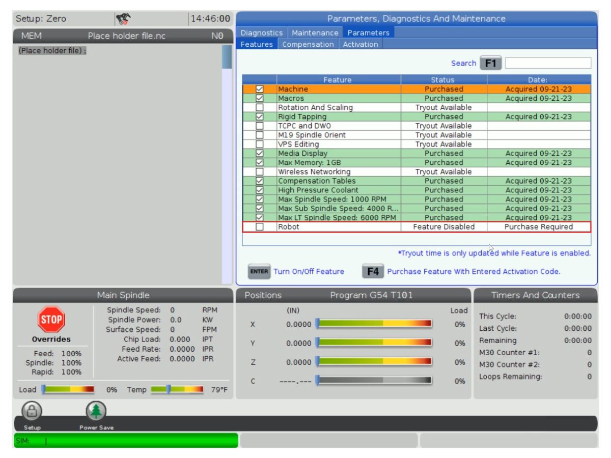
Go to Parameters > Features > Robot to verify that the robot feature has appeared on the bottom.

3

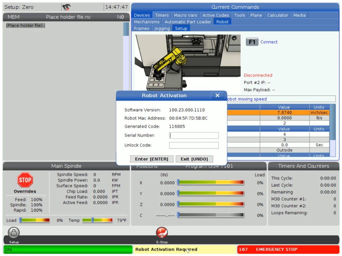
Press [CURRENT COMMANDS].

Go to Devices>Robot>Setup tab [1].

Press [E-Stop].

Press [F1] to connect the robot[2].

The first time connecting a robot to a machine, the robot feature will need to be unlocked. This popup shows the machine's current software version, robot mac address and a generated code. Enter this information into HBC in order to receive the unlock code.

4

On HBC, go to the Service tab [1].

On the left hand side of the screen, click on Activations [2], and then select Cobot Installation [3] to begin the process to the get the Cobot unlock code.

The first step is to enter the Machine Serial Number [4] and the Cobot Serial Number [5] in the fields on HBC.

Once you have entered the correct information, press Next [6] in the bottom right corner and continue through the steps until you receive the unlock code.

Note: Make sure you are on the Cobot Installation tab [3] and not the Robot Installation tab. The Robot Installation is only used for the Haas Robot Packages. Using the Robot Installation for the Haas Cobots will result in an invalid unlock code.

5

Enter the Cobot's Haas Serial Number[1] and the unlock code to connect the robot to the machine. 

 Note: This step can only be completed by a HFO Service Technician.

 Note: The machine needs to be activated before the Cobot is activated. Follow the Machine Activation / Time Extension - NGC procedure.

When the robot has connected with the machine, a yellow message saying Robot Activation Successful should appear at the bottom of the Haas screen.

6

Release the [E-STOP] and press RESET to clear the alarms. 

Press the [HANDLE JOG] button. 

Press the [CURRENT COMMANDS]  and go to Devices > Robot > Jogging tab.

 Note: The robot in setup mode can only be handle jogged while the F2 button the RJH is pressed. See Setup/Run mode section below.

On the Remote Handle Jog Touch press the Joint button to go into the Joints Coordinates.

Move the robot to an accessible location to install the grippers.

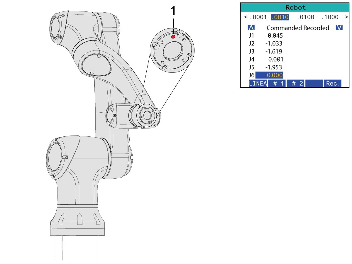
Jog J6 to 0.0000 position. The location hole should be centered on top.

Note: Press [E-STOP] before working on the robot.

Gripper Installation

1

Turn off the machine air by turning the valve in the Air/Lube cabinet and pull the pressure relief valve to release the air in the system.

2

For the Dual Action Gripper:

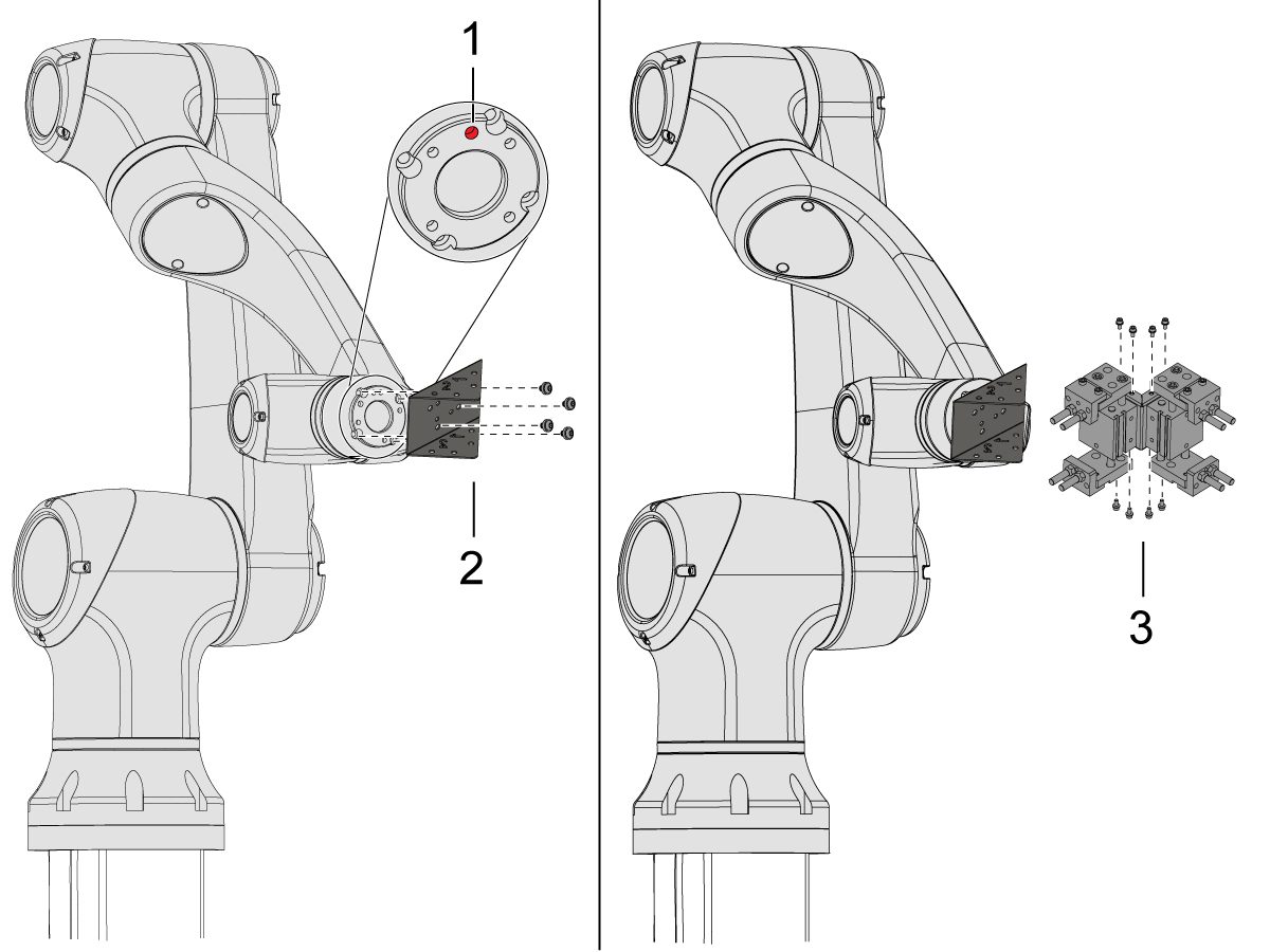
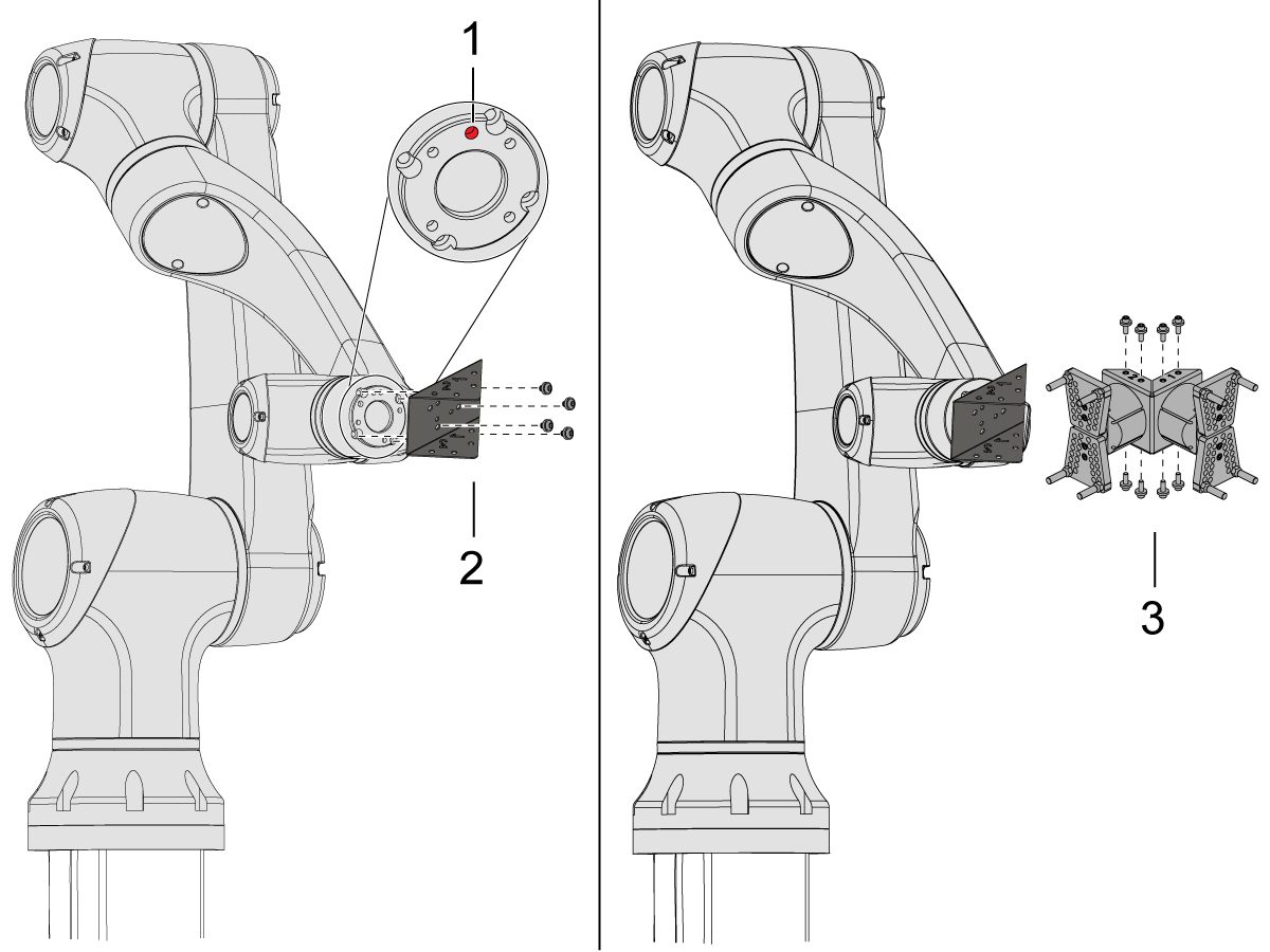
There are two versions of the dual-action grippers for this section, both of which have the same installation process.

Jog the robot so that the location hole [1] is centered on top.

Install the adapter plate [2] onto the end of the robot arm.

Install the dual gripper assembly [3] onto the adapter plate [2].

NOTE: Make sure to install Gripper 1 (which has the orange and purple zip ties) onto the Gripper 1 adapter plate section. 

3

For the Angled Single Action Gripper:

Jog the robot so that the location hole [1] should be centered on top.

Install the angle adapter plate [2] to the end of the robot arm.

Install the single gripper assembly [3] onto the angle adapter plate [2]. 

4

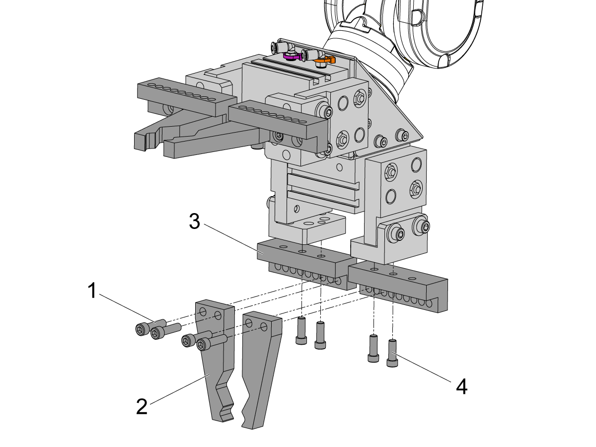
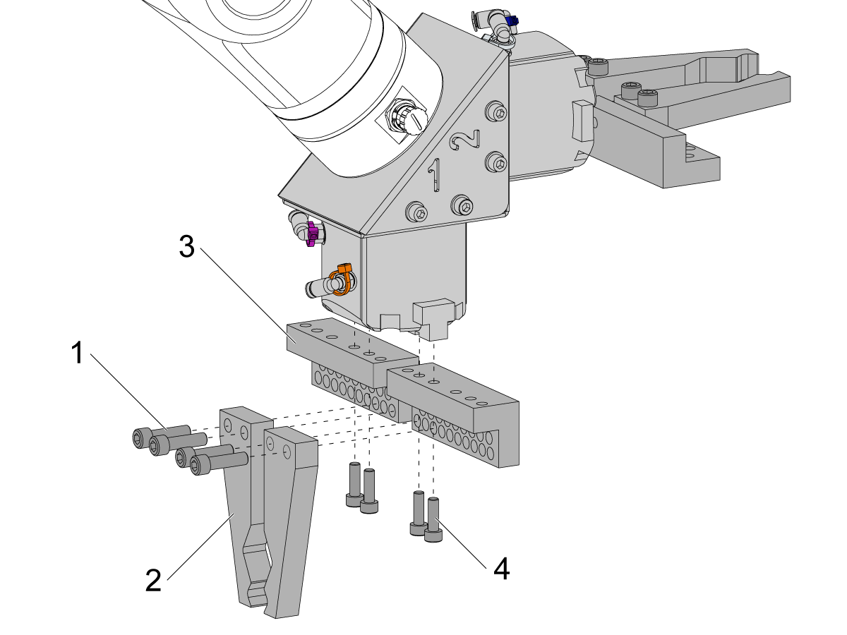
To install the bar gripper fingers, remove the slug gripper plates from the gripper bodies.

Install the Bar Gripper Bolt Plates [3] with (x8) SHCS M6 screws [4]. Torque to 10 ft-lbs.

Install the Bar Gripper Fingers [2] with (x8) SHCS 1/4-20 [1]. Torque to 13 ft-lbs.

5

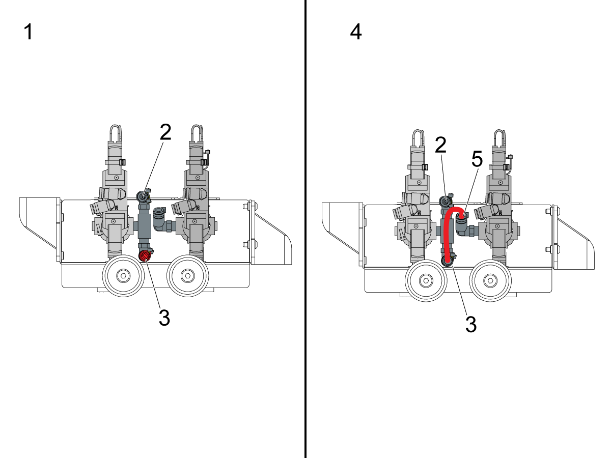
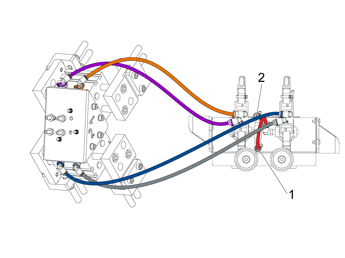
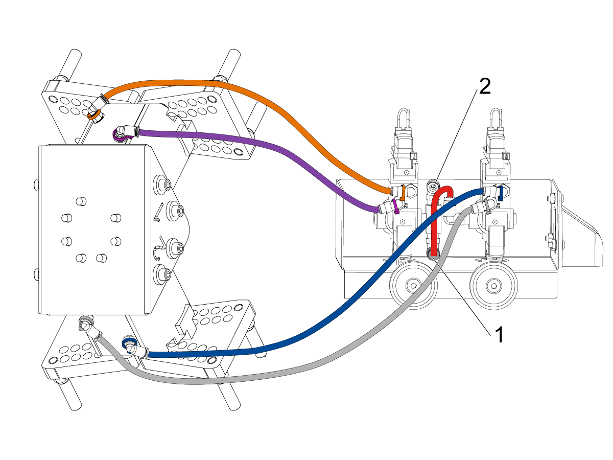
Configure the dual air solenoid assembly used for pneumatic grippers depending on single [1] or dual [2] gripper configuration. 

For single grippers [1], connect the incoming air to the to the fitting [2] and keep the plug in the other end of the fitting [3] as shown in the image.

For dual grippers [4], remove the plug in the fitting [3] and attach a small air hose to the second solenoid [5]. Then connect the incoming air hose to the fitting [2] so that both solenoids are receiving air.

6

For the Single Gripper:

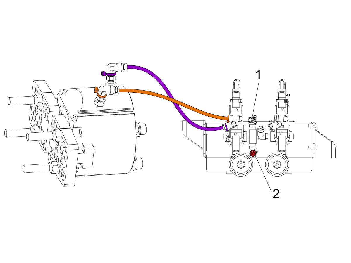
Route the (x2) air lines from the gripper to the same color coded fitting on the dual air solenoid assembly. 

Secure the air lines by wrapping them in cable conduit. Use the velcro straps to attach the cable conduit to the Cobot. Make sure there is enough slack so that cables aren't strained when Cobot is fully extended.

Insert the input air hose to the used solenoid's fitting [1]. 

Make sure the plug is installed onto the unused solenoid's fitting [2]. 

7

For the Dual Gripper:

Route the (x2) air lines from gripper #1 to the same color coded fitting on the dual air solenoid assembly. 

Route the (x2) air lines from gripper #2 to the same color coded fitting on the dual air solenoid assembly. 

Secure the air lines by wrapping them in cable conduit. Use the velcro straps to attach the cable conduit to the Cobot. Make sure there is enough slack so that cables aren't strained when Cobot is fully extended.

Insert the short airline [1] connecting the first solenoid with the second. 

Insert the input air hose to the fitting [2]. 

Parts Table Assembly

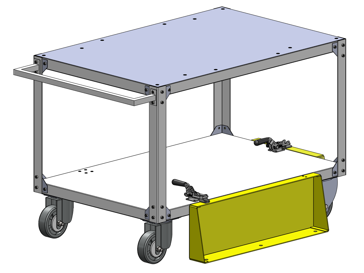
If the parts table option was ordered, follow the procedure below for assembly instructions:

Haas Robot - Parts Table Assembly

NOTE: If HC10 MACHINE READY KIT was purchased, there is no need to install the wheels if mounting the parts table directly into the wooden pallet. 

Verification

Test the E-stop:

  • Press each E-STOP button located on the Haas Pendant, RJH-XL, and Cobot Teach Pendant. Make sure the machine generates 107 EMERGENCY STOP alarm.  If the E-STOP button does not generate a 107 EMERGENCY STOP alarm verify the wiring. Load the latest configuration files to enable the RJH-XL.

Test the Robot Safety Device:

Make sure that there is an E-STOP or light curtain triggered icon on the Haas pendant when the robot safety device is triggered. 

  • Fence - Insert the key into the interlock, verify that the two red LED lights in the front of the interlock are OFF. Remove the key from the interlock, verify that the two red LED lights are ON. 
  • Area Scanner - Step inside the protective field, verify that the red LED lights up on the area scanner. Step outside the protective field, verify that the green LED lights up.
  • Light Curtain - Interfere the light curtain beams, verify that the light curtain triggered icon appears on the Haas pendant. Press [RESET]. Step outside of the light curtain beams, verify no icon appears on the Haas pendant. 

NOTE: If the light curtain triggered icon does not show, verify wiring, alignment and factory setting: 2191 [694:] LIGHT CURTAIN TYPE is set to LC_TYPE_1.

Test the Operation of the Grippers:

  • Verify that both grippers clamp and unclamp correctly.
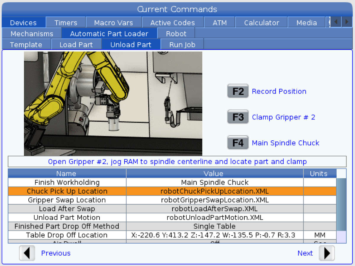
  • Press the [CURRENT COMMANDS]  and go to Devices > Robot > Jogging tab.
  • Press [F2] to clamp/unclamp the Finish Gripper.
  • Press [F3] to clamp/unclamp the Raw Gripper.

Test the Remote Jog Handle:

  • Undock the Remote Jog Handle
  • Press the [HANDLE JOG] button. 
  • Press the [CURRENT COMMANDS]  and go to Devices > Robot > Jogging tab.
  • On the Remote Handle Jog press the Joint button to go into the Joints Coordinates.
  • Move the robot to a safe location.

IMPORTANT: If a yellow warning message appears saying "Please activate Light Curtain or Cell Safe" while trying to job the robot, verify the safety parameter was applied by re-uploading the configuration files from HBC. 

Verify Safe / Run Mode Operation

All Haas CNC machines are equipped with a key switch on the side of the control pendant to lock and unlock setup mode. The robot will have the following behaviors depending on what mode is selected. 

  • When the Haas control is in Run mode, mode 1, triggering the robot safety device stops all motion. This motion can not be started until the robot safety device is no longer triggered.
  • When the Haas control is in Set up mode, mode 2, speed limited motion such as jogging an axis of the robot can be performed in order to program a robot's path of motion, pick up position, set a robot's tool center point, (an offset), load and pick up parts from the spindle or part holder in the machine, etc. The programmed path will also be able to be run slowly to prove out the programmed path of the robot. The robot in setup mode can only be handle jogged while the F2 button the RJH is pressed.

Haas Robot - Quick Start Guide

Stel na het installeren van de robot een taak op volgens de onderstaande procedure.

Haas Robot - Snelstartgids

Disable the Robot

Om de robot uit te schakelen om de machine in stand-alone-modus te laten draaien. Druk op [SETTING]. Wijzig de volgende instellingen:

  • 372 Werkstuk lader type naar 0: GEEN
  • 376 Lichtgordijn ingeschakeld naar Uit

Recently Viewed Items

You Have No Recently Viewed Items Yet

Feedback
Haas Logo

Leveringsprijs Haas

Deze prijs is inclusief verzendkosten, export- en invoerrechten, verzekeringen en andere kosten tijdens verzending naar een locatie in Frankrijk die met u als koper is overeengekomen. Er kunnen geen andere verplichte kosten worden toegevoegd aan de levering van een Haas CNC-product.

BLIJF OP DE HOOGTE VAN DE NIEUWSTE TIPS EN TECHNOLOGIE VAN HAAS…

Meld u nu aan!   

HAAS TOOLING ACCEPTEERT HET VOLGENDE:

  • Service en ondersteuning
  • Eigenaren
  • Service aanvragen
  • Bedieningshandleidingen
  • Haas-onderdelen
  • Reparatieverzoek voor draaitafel
  • Handleidingen voor het voorinstalleren
  • Winkelen voor gereedschap
  • Een nieuwe Haas samenstellen en prijs bepalen
  • Beschikbare voorraad
  • De prijslijst van Haas
  • CNCA financiering
  • Over Haas
  • Toegankelijkheidsverklaring
  • DNSH-verklaring
  • Naleving van exportvoorschriften
  • Carrières
  • Certificeringen en veiligheid
  • Neem contact met ons op
  • Geschiedenis
  • Algemene voorwaarden
  • Algemene voorwaarden Haas Tooling
  • Privacy
  • Garantie
  • Haas-gemeenschap
  • HAAS-certificeringsprogramma
  • Haas Motorsports
  • Gene Haas Foundation
  • Haas gemeenschap technisch onderwijs
  • Evenementen
  • Doe mee aan de conversatie
  • Facebook
  • X
  • Flickr
  • YouTube
  • LinkedIn
  • Instagram
  • TikTok
© 2026 Haas Automation, Inc - CNC werktuigmachines

This site is protected by reCAPTCHA and the Google Privacy Policy and Terms of Service apply.

2800 Sturgis Rd., Oxnard, CA 93030 / Toll Free: 800-331-6746
Phone: 805-278-1800 / Fax: 805-278-2255