My Haas Welcome,
!
Haas Tooling MyHaas/HaasConnect Sign In Register Haas Tooling MyHaas/HaasConnect Sign Out Welcome, My Machines Latest Activity My Quotes My Account My Users Sign Out
Find Your Distributor
  1. Select Language
    1. English
    2. Deutsch
    3. Español - ES
    4. Español - MX
    5. Français
    6. Italiano
    7. Português
    8. Český
    9. Dansk
    10. Nederlands
    11. Magyar
    12. Polski
    13. Svenska
    14. Türkçe
    15. 中文
    16. Suomi
    17. Norsk
    18. الإنجليزية
    19. български
    20. Hrvatski
    21. Ελληνικά
    22. Română
    23. Slovenský
    24. Slovenščina
    25. 한국어
    26. 日本語
    27. Українська
  • machines Main Menu
    • Vertical Mills
      Vertical Mills
      Vertical Mills View All
      • Vertical Mills
      • VF Series
      • Universal Machines
      • VR Series
      • VP-5 Prismatic
      • Pallet-Changing VMCs
      • Mini Mills
      • Mold Machines
      • High-Speed Drill Centers
      • Drill/Tap/ Mill Series
      • Toolroom Mills
      • Pocket Mill
      • Compact Mills
      • Gantry Series
      • SR Sheet Routers
      • Extra-Large VMC
      • Double-Column Mills
      • 3+2 Positioning Machines
    • Multi-Axis Solutions
      Multi-Axis Solutions
      Multi-Axis Solutions View All
      • Multi-Axis Solutions
      • Y-Axis Lathes
      • 5-Axis Mills
    • Lathes
      Lathes
      Lathes View All
      • Lathes
      • ST Series
      • Dual-Spindle
      • Box Way Series
      • Toolroom Lathes
      • Chucker Lathe
      • Pocket Lathe
      • Haas Bar Feeders
    • Horizontal Mills
      Horizontal Mills
      Horizontal Mills View All
      • Horizontal Mills
      • 50-Taper
      • 40-Taper
    • Rotaries & Indexers
      Rotaries & Indexers
      Rotaries & Indexers View All
      • Rotaries & Indexers
      • Rotary Tables
      • Indexers
      • 5-Axis Rotaries
      • Extra-Large Rotaries
    • Special Series
      Special Series
      Special Series View All
      • Special Series
      • EU_Series_Redirect
    • Automation Systems
      Automation Systems
      Automation Systems View All
      • Automation Systems
      • Mill Automation
      • Lathe Automation
      • Automatic Parts Loaders
      • Automation Models
    • Desktop Machines
      Desktop Machines
      Desktop Machines View All
      • Desktop Machines
      • Desktop Mill
      • Desktop Lathe
      • Control Simulator, Standard
      • Control Simulator, Premium
    • Shop Equipment
      Shop Equipment
      Shop Equipment View All
      • Shop Equipment
      • Knee Mill
      • Haas Manual Lathes
      • Haas Saws
    • Fabrication Machines
      Fabrication Machines
      Fabrication Machines View All
      • Fabrication Machines
      • Laser Cutting Machines
      • CNC Press Brakes
    • QUICK LINKS Special Series  Special Series 
      EU SERIES EU SERIES BUILD & PRICE | PRICE LIST BUILD & PRICE | PRICE LIST In-Stock Machines In-Stock Machines WHAT’S NEW WHAT’S NEW YOUR FIRST CNC YOUR FIRST CNC
      SHOPPING TOOLS
      • Build & Price a Haas
      • Price List
      • Available Inventory
      • CNCA Financing
      WANT TO TALK TO SOMEONE?

      A Haas Factory Outlet (HFO) can answer your questions, and walk you through your best options.

      CONTACT YOUR DISTRIBUTOR >
  • Options Main Menu
    • The Haas Control Value Option Packages
      Value Option Packages
      Value Option Packages View All
      • Value Option Packages
    • Product Image Spindles
      Spindles
      Spindles View All
      • Spindles
    • Product Image Tool Changers
      Tool Changers
      Tool Changers View All
      • Tool Changers
    • Product Image 4th- | 5th-Axis
      4th- | 5th-Axis
      4th- | 5th-Axis View All
      • 4th- | 5th-Axis
    • Product Image Turrets & Live Tooling
      Turrets & Live Tooling
      Turrets & Live Tooling View All
      • Turrets & Live Tooling
    • Product Image Probing
      Probing
      Probing View All
      • Probing
    • Haas Chip & Coolant Management Chip & Coolant Management
      Chip & Coolant Management
      Chip & Coolant Management View All
      • Chip & Coolant Management
    • The Haas Control The Haas Control
      The Haas Control
      The Haas Control View All
      • The Haas Control
    • Product Image Product Options
      Product Options
      Product Options View All
      • Product Options
    • Product Image Tooling & Fixturing
      Tooling & Fixturing
      Tooling & Fixturing View All
      • Tooling & Fixturing
    • Product Image Workholding
      Workholding
      Workholding View All
      • Workholding
    • Product Image 5-Axis Solutions
      5-Axis Solutions
      5-Axis Solutions View All
      • 5-Axis Solutions
      • 5 Easy Steps to 5-Axis
    • QUICK LINKS Special Series  Special Series 
      EU SERIES EU SERIES BUILD & PRICE | PRICE LIST BUILD & PRICE | PRICE LIST In-Stock Machines In-Stock Machines WHAT’S NEW WHAT’S NEW YOUR FIRST CNC YOUR FIRST CNC
      SHOPPING TOOLS
      • Build & Price a Haas
      • Price List
      • Available Inventory
      • CNCA Financing
      WANT TO TALK TO SOMEONE?

      A Haas Factory Outlet (HFO) can answer your questions, and walk you through your best options.

      CONTACT YOUR DISTRIBUTOR >
  • Why Haas Main Menu
      Discover the Haas Difference
    • Why Haas
    • MyHaas
    • Education Community
    • Industry 4.0
    • Haas Certification
    • Customer Testimonials
  • Service Main Menu
      Welcome to Haas Service
      SERVICE HOME Operator’s Manuals How-To Procedures Troubleshooting Guides Preventive Maintenance Haas Parts Haas Tooling Videos
  • Videos Main Menu
  • Main Menu
    • View All
    • View All
    • View All
    • View All
      • HTEC Curriculum Support
      • Haas Value Option Packages (VOP) Journey
    • View All
      • Haas 10 kg Cobot Package
      • Cobot Kits
      • DC-1 Drill Center
      • CNC Sales News
      • Do More With Your Haas
    • View All
    • View All
      • contact-us-test
      • 4 - AUTOMATION SYSTEMS
      • Carousel-V2
      • expert test
      • Demo_Day_Trident-test
      • Link Test
      • image-sale-tag-test
      • article-list-test
      • Haas 25 kg Robot Package
      • test-algolia-page
    • View All
    • View All
    • View All
    • View All
      • calc-test
    • View All
    • QUICK LINKS Special Series  Special Series 
      EU SERIES EU SERIES BUILD & PRICE | PRICE LIST BUILD & PRICE | PRICE LIST In-Stock Machines In-Stock Machines WHAT’S NEW WHAT’S NEW YOUR FIRST CNC YOUR FIRST CNC
      SHOPPING TOOLS
      • Build & Price a Haas
      • Price List
      • Available Inventory
      • CNCA Financing
      WANT TO TALK TO SOMEONE?

      A Haas Factory Outlet (HFO) can answer your questions, and walk you through your best options.

      CONTACT YOUR DISTRIBUTOR >
  • Haas Tooling Main Menu
  • Haas Service Parts Main Menu

My Haas Welcome,
!
Haas Tooling MyHaas/HaasConnect Sign In Register Haas Tooling MyHaas/HaasConnect Sign Out Welcome, My Machines Latest Activity My Quotes My Account My Users Sign Out
Find Your Distributor
  1. Select Language
    1. English
    2. Deutsch
    3. Español - ES
    4. Español - MX
    5. Français
    6. Italiano
    7. Português
    8. Český
    9. Dansk
    10. Nederlands
    11. Magyar
    12. Polski
    13. Svenska
    14. Türkçe
    15. 中文
    16. Suomi
    17. Norsk
    18. الإنجليزية
    19. български
    20. Hrvatski
    21. Ελληνικά
    22. Română
    23. Slovenský
    24. Slovenščina
    25. 한국어
    26. 日本語
    27. Українська
×

Search Results

Web Pages

Images

    • <
    • 1
    • >

VF-4 Pallet Pool - 5 + 1 Station - Installation - AD0803

Service Home How To Procedures VF-4 Pallet Pool - 5 + 1 Station - Installation - AD0803

VF-4 Pallet Pool - 5 + 1 Station - Installation - AD0803

- Jump to Section - Back to Top

4.4 VF-4 PP - 5 + 1 Station

Recently Updated Last updated: 11/07/2024

VF-4 Pallet Pool - 5 + 1 Station - Installation


Revision E - 03/2026

Introduction

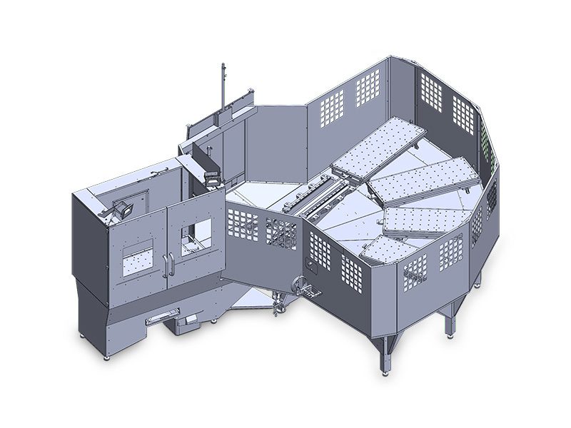
The following procedure will show you how to install a 5 station Pallet Pool on the following machines:

  • VF-4
  • VF-4SS

The Next Generation software on the machine must be version 100.22.000.1010 or higher.

The Pallet Pool option is not field installable.

The VF-4 must be level and anchored before the Pallet Pool can be installed. Refer to the VMC-Installation procedure.

The Pallet Pool option has a room for a total of 6 pallets that can be installed on a VF-4 with the Pallet Pool option.

The Pallet Pool has 2 servo axes. The PR axis rotates the Pallet Pool saddle and the PS axis extends and retracts the Pallet Pool saddle to load/unload the pallets.

Pre-Requisites to Pallet Pool Installation

1

Updated

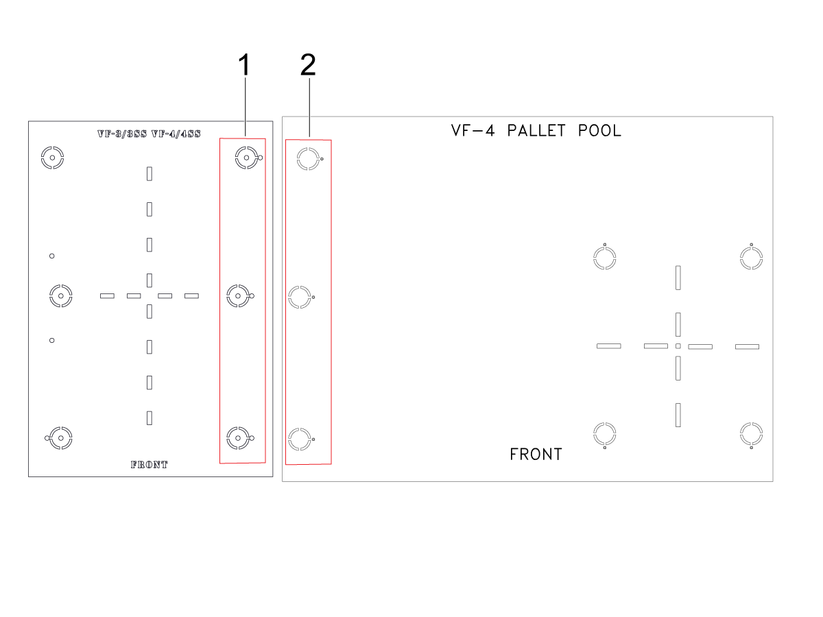
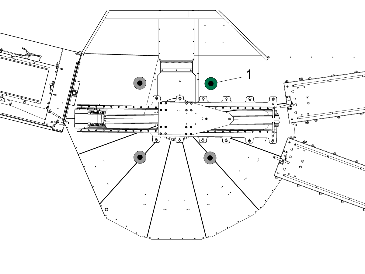
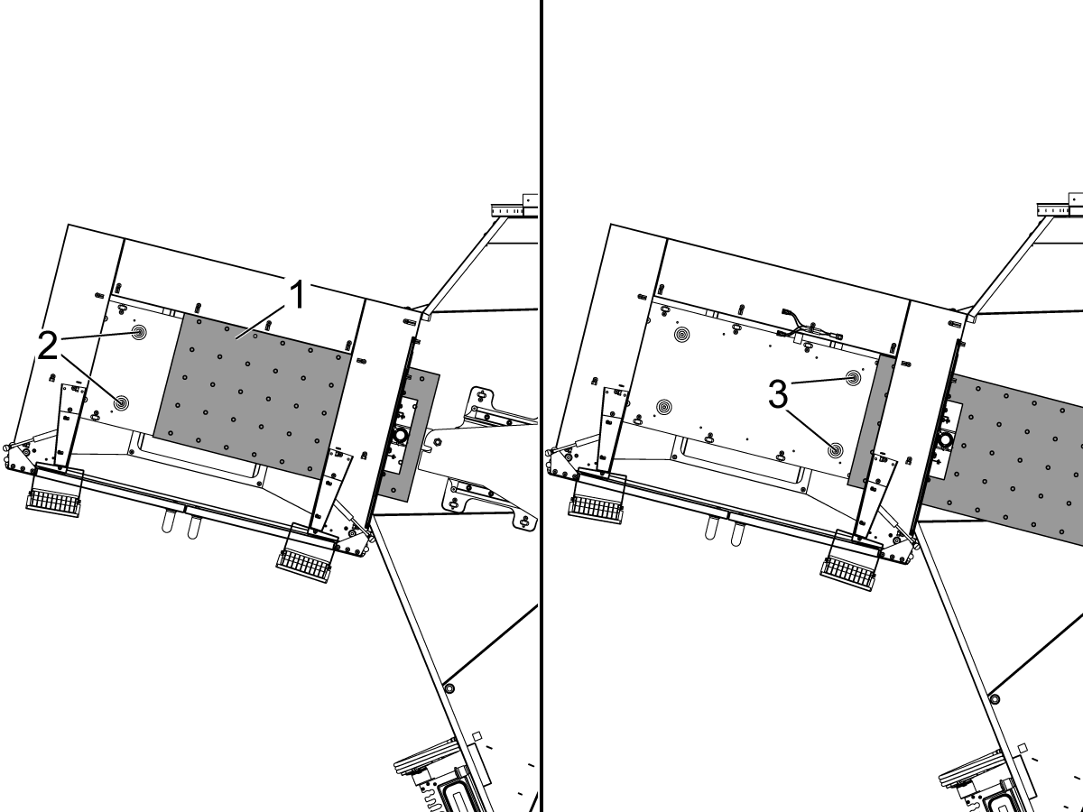
The machine and Pallet Pool should be placed using the anchoring templates. Place the templates over one another so that the points in boxes [1] and [2] line up with each other. View the image for reference.

Important: To ensure that the Pallet Pool does not become mis-aligned, it is required that the machine and Pallet Pool be anchored after leveling. Refer to the following link: Anchoring Instructions.

The VF-4 must be level and anchored before the Pallet Pool can be installed. Refer to the VMC-Installation procedure.


2

Updated

If the VF-4 pallet pool machine is ordered with the 120 pocket SMTC AND the quad-auger with conveyor system, the conveyor will be shipped coming out the right side of the machine to help with counter balancing the weight of the tool changer. 

The conveyor MUST be moved to come out the left side of the machine to make room for the pallet pool to fit against the right side of the machine at install.

This should be done before placing the VF-4/SS in its final position if space is limited or can be done after installation of the machine, only if there is enough to pull out the conveyor and reinsert it through the left side of the machine in its final installation location.

Leveling Screws Hardware

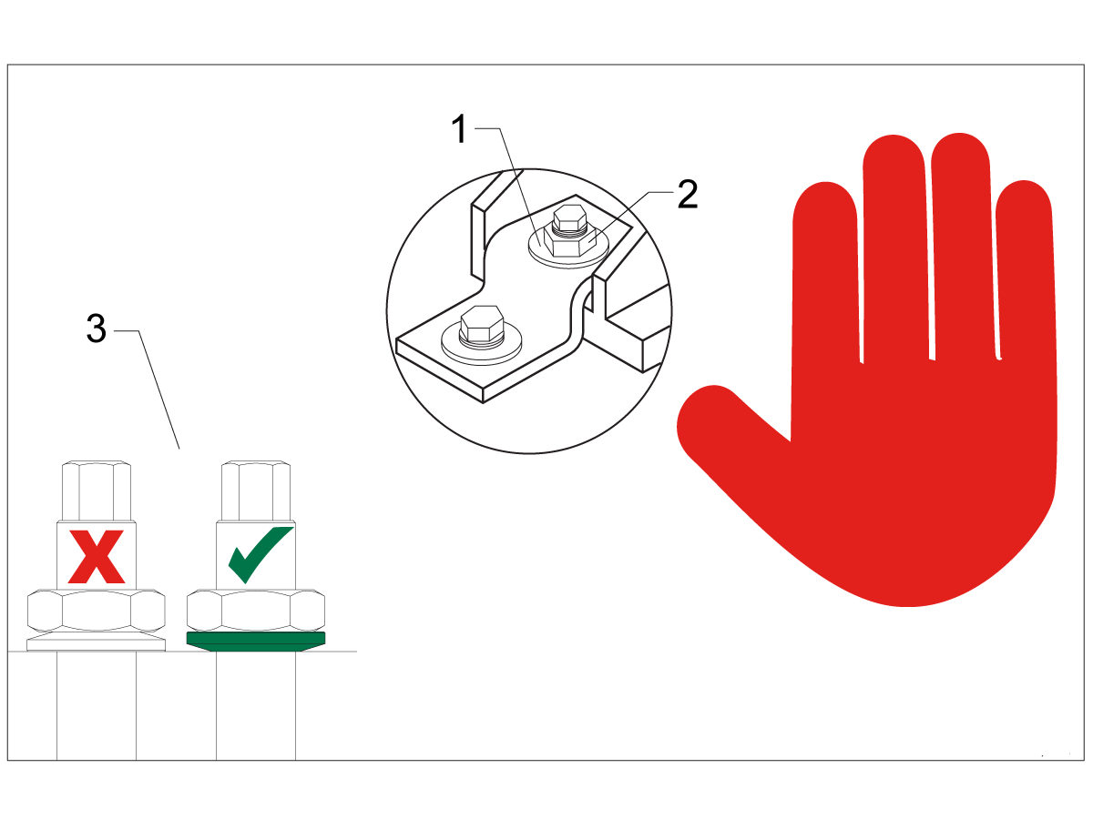
Note: The washers [1] and nuts [2] are installed during shipping and should be saved for installation and not be discarded.

Note: The washer orientation [3] is important.  The conical part of the washer should be against the casting,  see illustration.

Mating the Pallet Pool

1

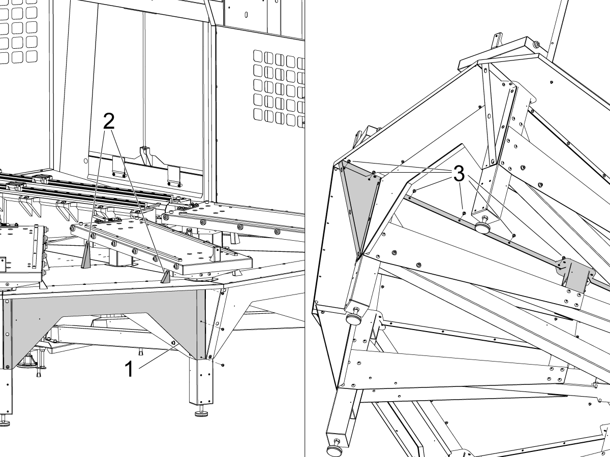
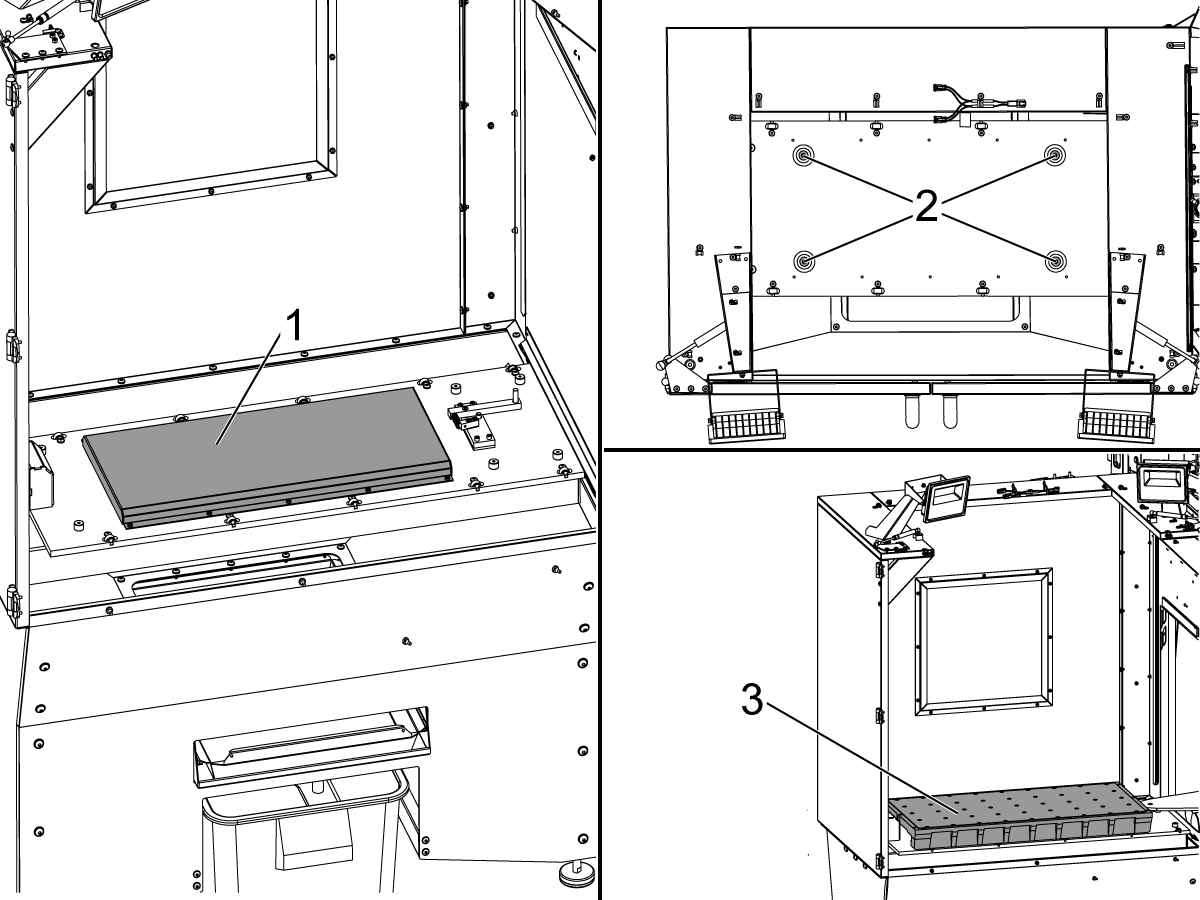
Install the two side drip pans [1] that lead to the VF-4 auto-window as shown followed by the middle drip pan [2].

2

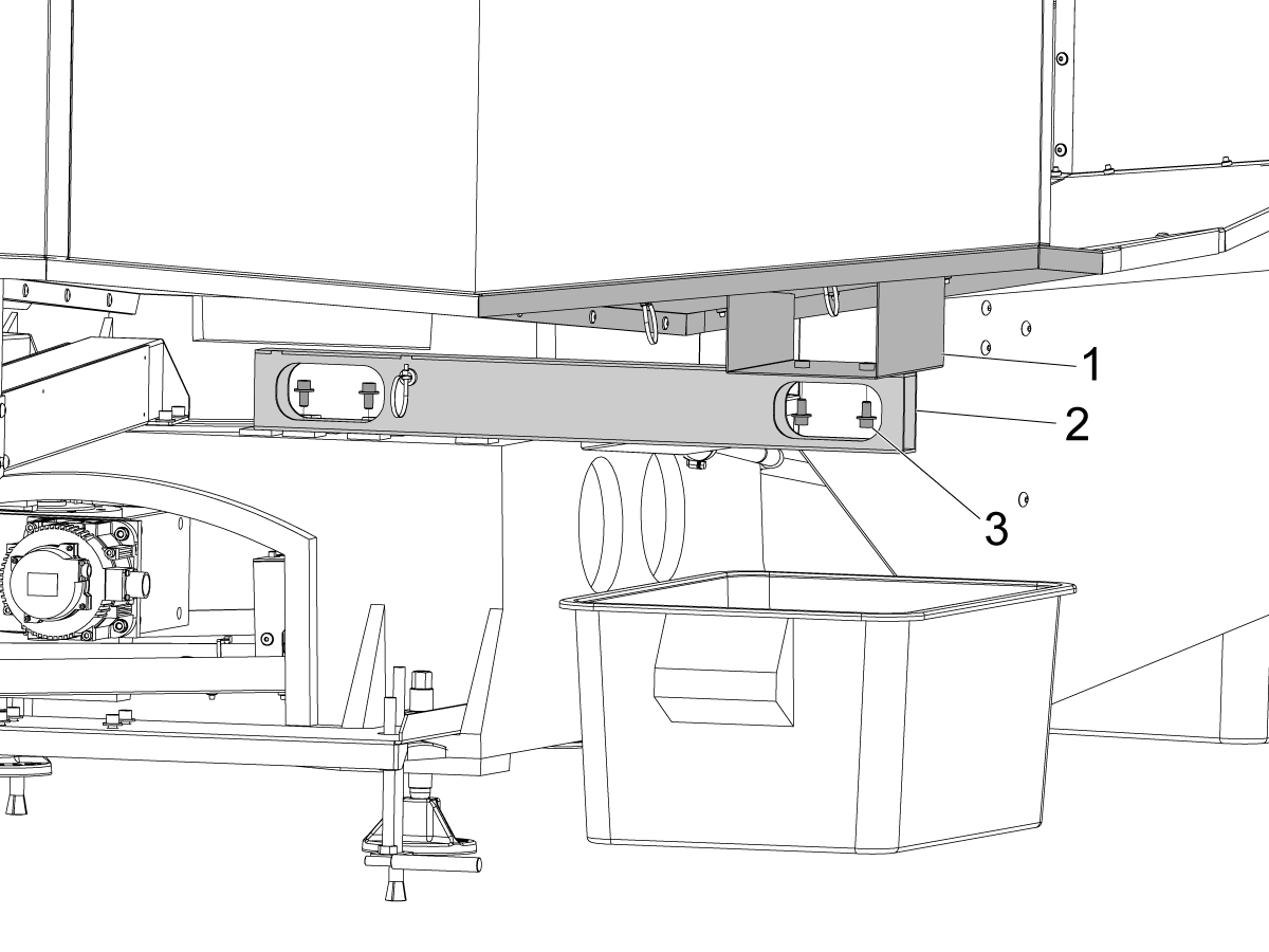
Install the pallet pool drip pan support [2] to help support the drip pan [1] . Use the provided hardware [3] to attach the support to the cast base and the drip pan.

3

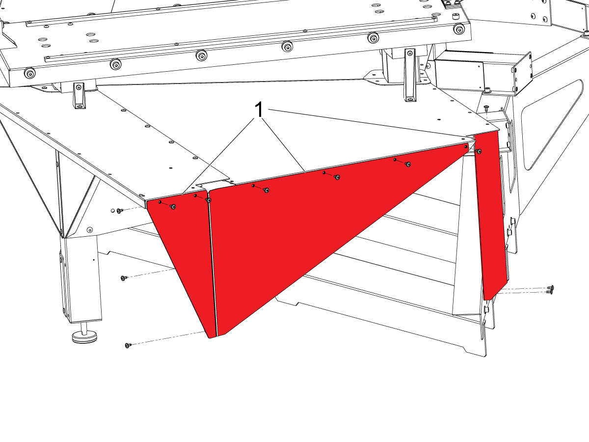
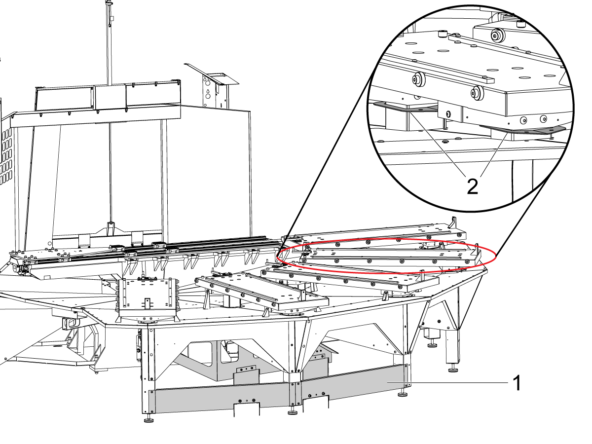
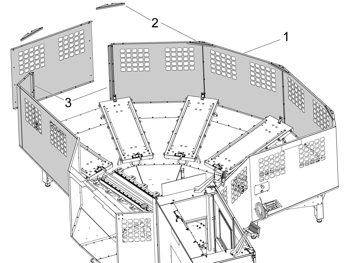
Install the sheet metal walls [1] and crossbar [2] shown. The cut out in the crossbar [2] will be the guide for where to move in the pallet pool to the machine.

4

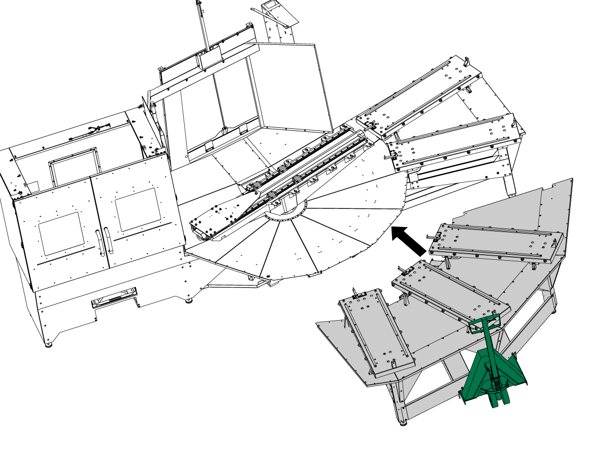
Use a pallet jack or forklift to move the pallet pool close to the machine. When moving the pallet pool into the machine, center the cross bar opening on the pallet pool around the sheet metal bracket that covers the air cylinder on the auto window of the machine.

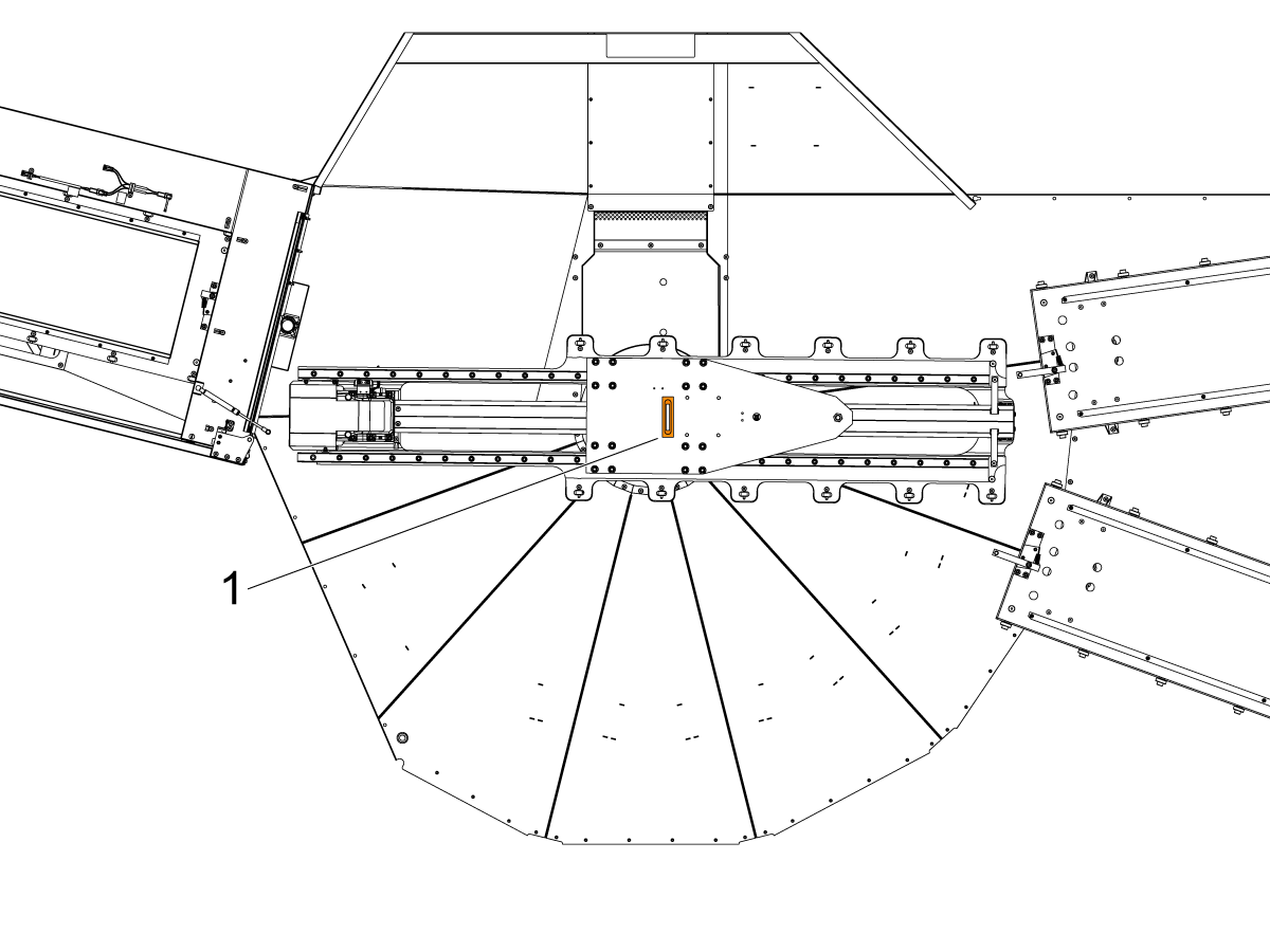
A decal has been placed on the rear of the pallet pool to indicate where the pallet forks should lift the pallet pool from.

 IMPORTANT: Do NOT attach the 3 station module before moving the pallet pool into the machine. Do NOT try to lift the whole pallet pool from the 3 station module, it will not properly hold the pallet pool.

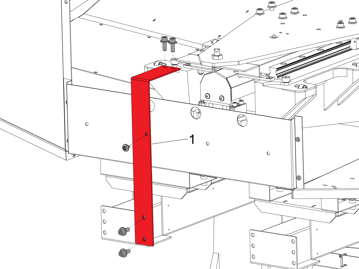
Shipping Brackets Removal

1

Remove the shipping bracket [1] from the Pallet Pool by removing the hardware and removing the bracket from the Pallet Pool's saddle.


2

Remove the Trolley Plate shipping bracket [1] by removing the two nuts and bolts.

3

Remove the latch covers [1] from the pallet pool by loosening the bolts and sliding off the latch cover.

Attach Load Station

1

Use a pallet jack or fork lift to lift the load station into position. 


2

Insert the provided the 8 bolts [1] to attach the load station to the pallet pool support arms.

Note: Use a screwdriver or something similar to help align the load station bolt hole before putting in the bolts.

3

Attach the pallet pool drip pan to the load station using the  1/4-20 button head bolts [1]. 

4

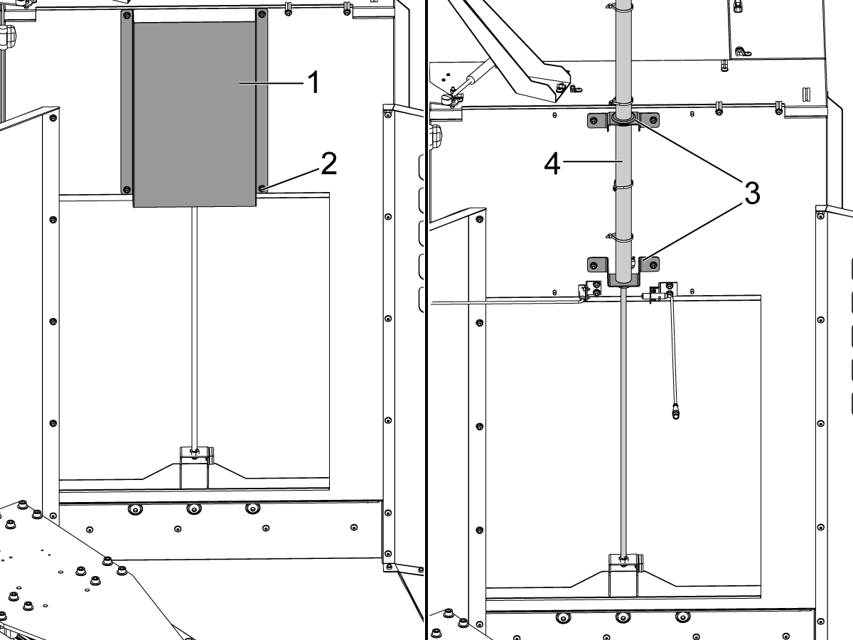
Remove the cover [1] and its hardware [2] to expose the air cylinder [4] of the automatic window on the load station and raise the air cylinder [4] so that the brackets [3] and air cylinder are attached as shown. Once the air cylinder is raised, reattach the cover [1].

Repeat this process for the air cylinder of the Auto Window on the VF-4. The gray and yellow air line tubing coming from the lube panel will need to be connected to the Auto Window air cylinder, the ports on the air cylinder will have gray and yellow zip ties to show where each tubing connects.

Note: Machines built June 2024 and later will now be equipped with the new clamp sensors on the Auto Windows, for proper sensor adjustment/alignment refer to the Clamp Sensor Alignment section of the VMC - Auto Window - Installation procedure.

5

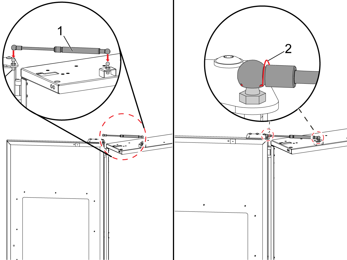
The load station door gas springs are in a zip lock bag zip tied to the load station doors.

Remove the retaining rings [2] from both sides of the gas spring [1].

Open the door and place the gas spring [1] on the ball studs as shown.

Install the retaining rings [2] on each side of the gas spring. 

Repeat this step for the second load station door.

6

The shipping feet [1] on the bottom of the pallet pool can be either taken off or folded in by loosening the screw and tucking them under the load station. 

Electrical and Pneumatic Connections

 Caution: When you do maintenance or repair on CNC machines and their components, you must always follow basic safety precautions. This decreases the risk of injury and mechanical damage.

  • Set the main circuit breaker to the [OFF] position.

 Danger: Before beginning any work inside the control cabinet the High Voltage indicator light on the 320V Power Supply / Vector Drive must have been off for at least 5 minutes.

Some service procedures can be dangerous or life-threatening. DO NOT attempt a procedure that you do not fully understand. If you have any doubts about doing a procedure contact your Haas Factory Outlet (HFO) and schedule a service visit.

1

Make sure the main circuit breaker is in the [OFF] position and wait until the Vector Drive High-Voltage light turns off.

Route the cables from the load station down the side of the load station under the pallet pool drip pan down to the electrical connection bracket.

Connect the Auto-Wind OP (cable 32-1147) to PP Inner Door Open on the electrical bracket.

Connect the Auto-Wind CL (cable 32-1179) to PP Inner Door Closed on the electrical bracket.

Connect the Autowindow Ext (cable 33-1402) to Window Open on the electrical bracket.

Connect the PP Load Door (cable 33-1401) to Pallet Load Door Open on the electrical bracket.

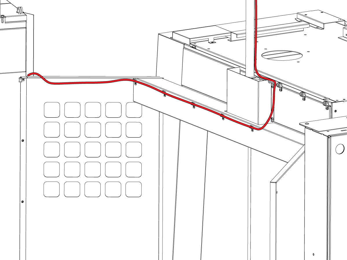
2

Attach the Autowindow Ext (cable 33-1402), which runs to the top of the pallet pool load station, to the prox sensor connection on the machine's auto window.  Run the cable along the top of the Pallet Pool as shown.

3

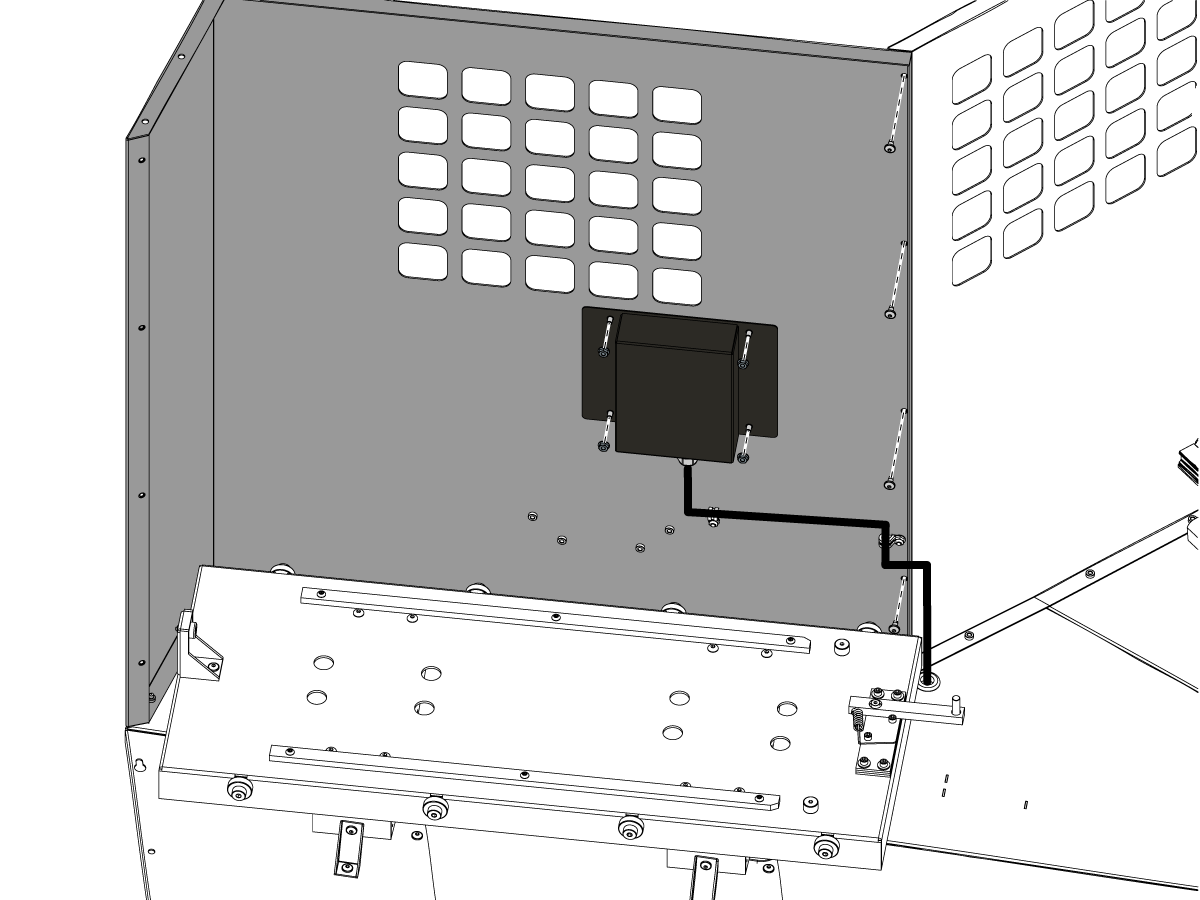
Route the pallet pool cables into the control cabinet as shown in the illustration.

 Note: The PR (Pallet Rotate) and PS (Pallet Slide) amps are already installed at the factory.

Note: Remove the panel under the electrical cabinet for access to the cables routed from the pallet pool.

Connect the PR motor encoder cable to Maincon PCB channel 15. Install the ferrite filter bead on the motor encoder cable.
Connect the PS motor encoder cable to Maincon PCB channel 16. Install the ferrite filter bead on the motor encoder cable.

Connect the PR motor power cable to the amplifier labeled PR. Install the ferrite filter bead on the motor power cable.

Connect the PS motor power cable to the amplifier labeled PS. Install the ferrite filter bead on the motor power cable.

Install the conduit on the cables going from the electrical connection bracket, the wires from the PS and PR motors, the work light cable and the pneumatic air hoses for the Pallet Pool inner auto window to the electrical cabinet and the CALM cabinet.

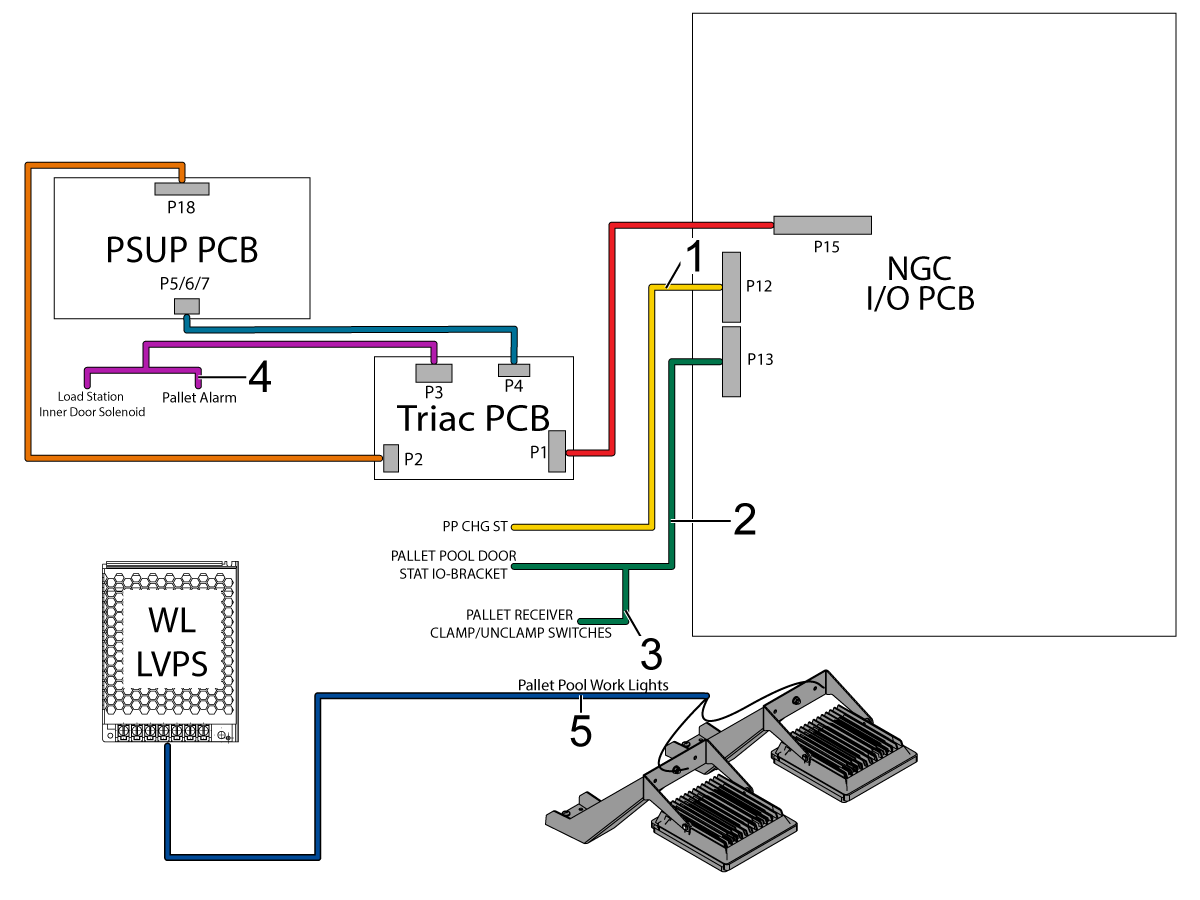
4

Remove the jumper from P12 and connect PP CHG ST (cable 33-1163) [1] to P12 on the  IOPCB.

Connect PALLET POOL DOOR STAT IO-BRACKET (cable 33-1114) [2] to P13 on the IOPCB.

Connect the Pallet Clamp wire to TSA SW NC PROX (cable 32-2348).

Connect the Pallet Unclamp wire to PP DOOR OPEN NO PROX (cable 32-0767). 

Note: The pallet clamp and unclamp connections are located under the electrical cabinet.

Connect PALLET ALARM (cable 33-1160) [4] to the pigtail on PP LOAD INNER (cable 33-1400) at P3 on the SMTC/Triac PCB.

For machines with CAN Lube panel, connect PALLET ALARM (cable 33-1160) [4]  to PP PALLET ALARM (cable 33-1613) which is plugged in at P3 on the SMTC/Triac PCB.

Connect the Pallet Load Station worklights (cable 33-5840) [5] to the Work Light LVPS power supply.

Make sure all the Pallet Pool status bracket connectors are plugged into the correct location.

5

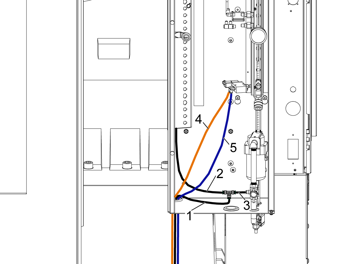
Route the air line with the T-fitting [1] from the pallet pool cable conduit into the lube panel as shown.

A small piece of air hose will need to be cut to connect to the air line in the lube cabinet [3].

Connect the air hose from the machine air gun [2] to the T-fitting as shown.

Route the orange [4] and blue [5] hoses from the inner load station window air cylinder to the bottom solenoid in the lube panel as shown. The ports on the solenoid will have orange and blue zip ties to show where each hose is connected.

6

Attach load station cable cover [1] to the side of the load station to cover the routed cables.

Note: Do not pinch the cables when putting on the cover.


Parameters and Settings

1

Set the main circuit breaker to the ON position.

Push [POWER ON].

Zero Return all the Axes

Do the following to enable the pallet pool option on a VF-4.  

Important:  You will need to do this step if you perform a option 5 clean install option on a VF-4 with a pallet pool.

Set setting 382 Disable Pallet Changer to None.

Note: Machine may need to cycle power for parameters to display. 

Find the Haas Pallet Pool Parameters decal near the lifting decal on the Pallet Pool machine. Write down the values.

Use the USB Service key to go into Service Mode.

Press [DIAGNOSTIC] Go to the PARAMETERS> Factory setting tab.

Set the Grid and TC offsets for PR and PS axis
 
  1. 15.078 PR-Axis Tool Change Offset = Use the decal value.
  2. 15.140 PR-Axis Grid Offset = Use the decal value.
  3. 16.078 PS-Axis Tool Change Offset = Use the decal value.
  4. 16.140 PS-Axis Grid Offset = Use the decal value.
  5. Zero Return after the grid offset is adjusted.

Base Level Pallet Pool

1

Verify all outer supports feet are NOT touching the floor.

Make sure the pallet pool sit on 3 points, the leveling foot that is not touching the puck is the one closest to the machine control cabinet [1].

The distance from the floor to the bottom on the Pallet Pool base should be approximately 3.5 inches.

2

Move the saddle to its home position if it is not already, place the bubble level on the trolley plate and rough level with respect to X & Y. 

NOTE: Rough level by adjusting the 3 leveling feet without adjusting the 4th in the air.

Once the base is leveled on the 3 points, bring the 4th leveling screw down to touch the pad.

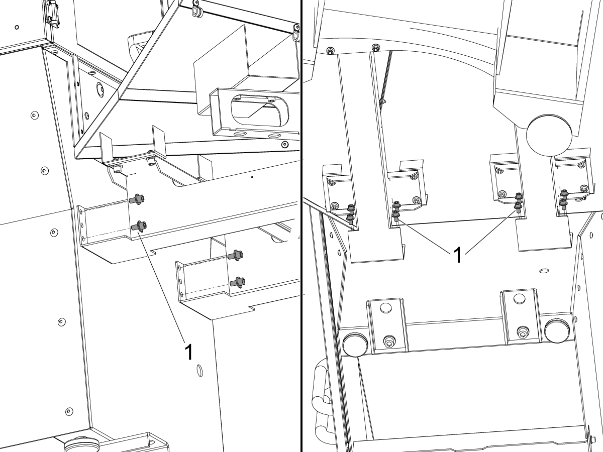
Attach The 3 Station Module

1

Remove the shipping brackets [1] on the side of the 3 station module.

2

Use a pallet jack to move in the 3 station module [1] to the main pallet pool assembly.

Make sure to lift the module [1] higher than the main pallet pool for easier movement into the main assembly.

3

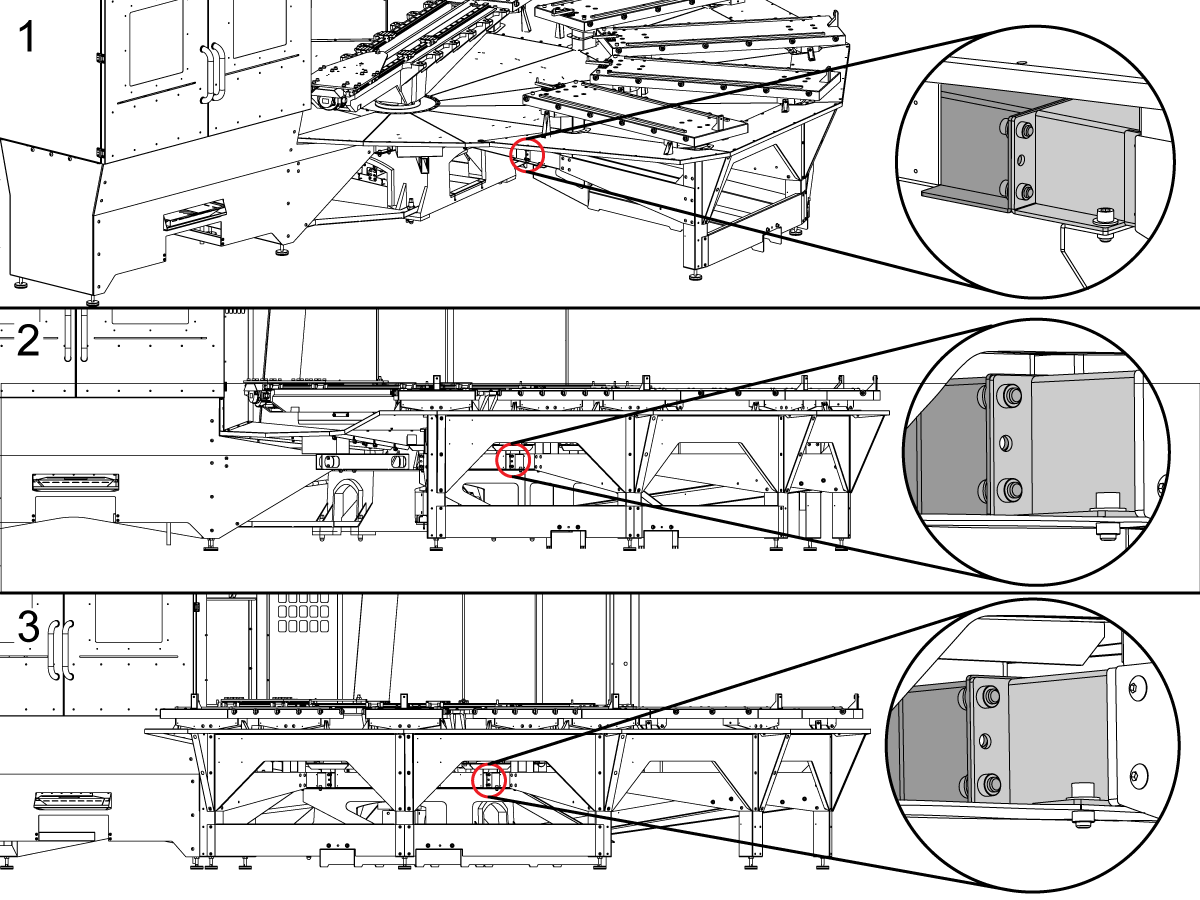
With the pallet jack still lifting the module while it is fully moved into the main assembly, install the top outer corner bolt to the bulkhead under station B as shown in [1]. Install the remaining 3 bolts under that bulkhead and verify all bolts are hand tight. 

Lower the pallet jack so that the module will line up the bulkhead underneath station C [2] and install the bolts at the bulkhead, verify they are hand tight before moving to the next bulkhead.

Lower the pallet jack again so that the module will line up the bulkhead underneath station D [3] and install the bolts at the bulkhead, verify they are hand tight.

Note: An alignment rod can be used in the middle hole of the bulkheads to help line up the bulkhead holes when installing the bolts.

4

If it is not already, completely lower the pallet jack and remove it from the module.

Remove the module's lifting mechanism [1] and push down the brackets [2] underneath station E. Screw down those plates with the screws provided.

5

At this point, the holes on the main pallet pool assembly and the 3 station module should line up, if they do not adjust the module legs until the holes are lined up.

Once the holes are lined up install the sheet metal bolts [1] underneath station E. Also make sure to get the bolts underneath station E shown with [3].

Install the legs [2] for station E.

6

Install the rest of of the bolts along where the module meets the main pallet pool [1].

Once all the bolts are installed and the module is fully attached to the main assembly go back underneath and completely tighten the bulkhead bolts.

If the pallet pool has any feet remaining in the air, go ahead and touch them down to the ground. Do not put any weight on them at this time, they will need weight when adjusting the shelves.

Shipping Support Bracket Removal Pallet Pool

1

Bring down the outer feet of the Pallet Pool and have them just touch the ground.

Remove the two shipping support brackets [1] from the pallet pool.

Note: The shipping support brackets are not painted red but do need to come off the pallet pool to install the inner leveling feet in the following section.

2

Once the shipping support brackets [1] have been taken off, they can be stored on the pallet pool. They can be stored on the main frame supports under the drip pans.

Attach Inner Leveling Feet

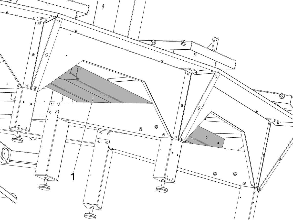
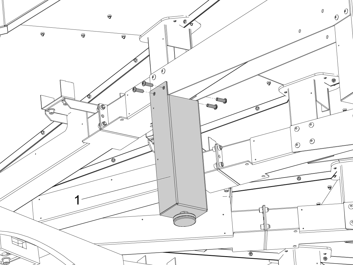
1

Take the support leg [1] and place it under the support arm. Use the provided hardware to attach the support leg to the support arm. Repeat this for all 5 support arms.

Bring down the support feet and have them touch the ground. Do not put any weight on them at this time, they may need some adjustment when adjusting the shelves.

Assigning Missing Pallets on Scheduler

1

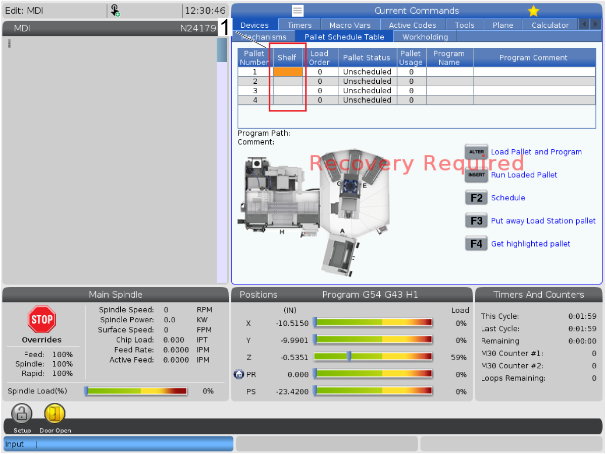
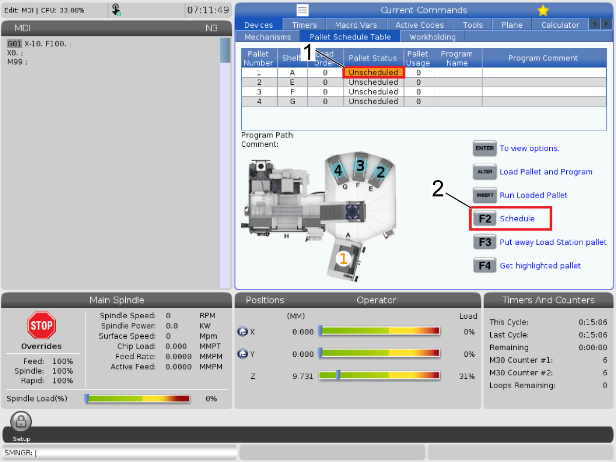
It is possible to enter a condition where the shelves in the pallet scheduling page are not assigned [1]. This will not allow the PR and PS to zero return or recover the machine. 

This section will explain how to assign the missing shelves, if your machine is not in this condition please skip to the next section. 

First, press [CURRENT COMMANDS] and navigate to the Pallet Schedule Table tab.

2

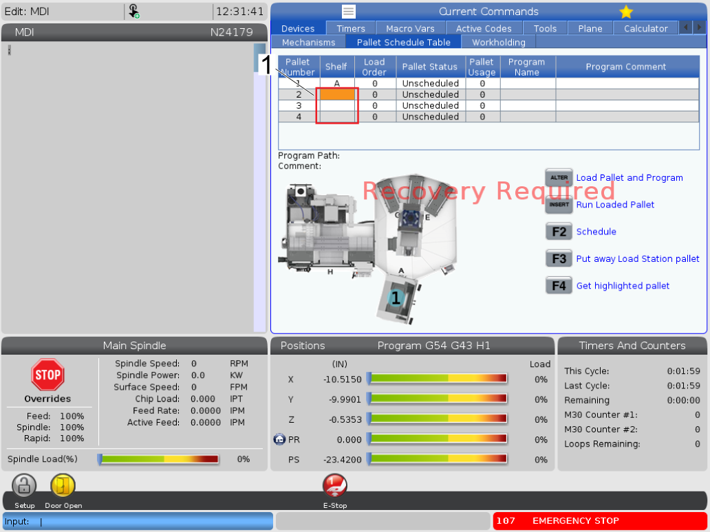
Press [EMERGENCY STOP] [1] and highlight the shelf tab on pallet number one.

With [EMERGENCY STOP] pressed, type the letter A and press [ENTER]. This will assign shelf A to pallet number 1 [2].

3

Repeat the previous step for the remaining pallet numbers in alphabetical number [1].

NOTE: The shelves can be re-assigned at any point  however the user chooses by repeating the same process (e.g. pallet number 3 can be assigned shelf B).

Align Pallet Drop Off Station

1

Insert the Service Key USB and put the machine in Service Mode.

Make sure there are no obstructions inside the machine or inside the pallet pool area. Pull out all the [E-STOPS] and [RESET] the alarms.

Press [ZERO RETURN] and then press [ALL]. The machine will zero return all the axes.

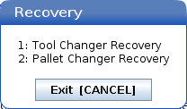
Once all the axis are zero returned press [RECOVER]. A pop up box will appear, select [2] for Pallet Changer Recovery.

2

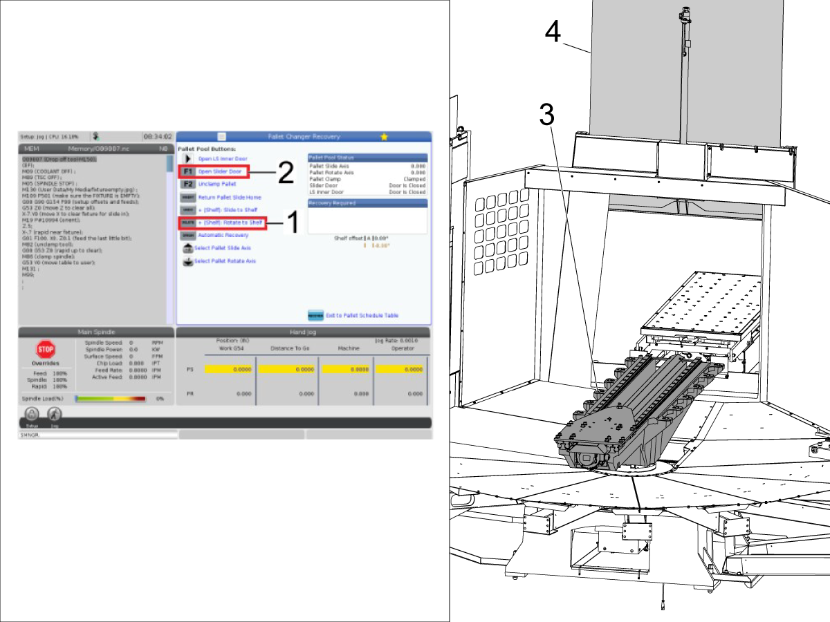
Press [G] and then the [DELETE] [1] button. This will rotate the saddle [3] towards station G (as shown in the image).

Press [F1] [2] to open the auto window [4].

3

Jog the X & Y axes to the positions the values in Factory Settings 1.310 and 2.310, respectively. 

Adjust the height on the pallet pool evenly if needed to be able to slide the pallet from the machine to the saddle.

In the Pallet Changer Recovery page press [F2] to unclamp the pallet [1] in the machine and try to manually slide the pallet [1] onto the pallet saddle [2]. Adjust Factory Setting 2.310 to adjust the y-axis position if necessary.

If more adjustment is needed once Factory Setting 2.310 is adjusted, adjust Factory Setting 2146 to adjust the shelf G PR offset.

Once the pallet saddle [2] and the receiver are properly aligned, manually jog the PR axis 4 degrees off and jog the PS and PR axes to manually hook the pallet.

Once the pallet is hooked and fully extended onto the receiver, set parameter 2136 [:] SHELF G SLIDE OFFSET.

In the Pallet Changer Recovery page while the pallet in the machine is hooked, press [INSERT] to return the pallet slide to home.

4

Once the pallet is moved off of the receiver, remove the nylon washers [1] that are on the (4) surrounding pins.

Align Pallet Loading Station

1

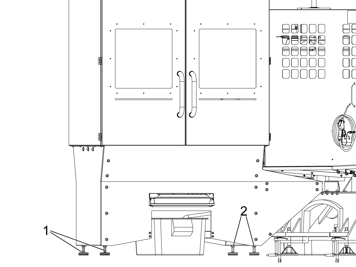
Level the load station by placing a bubble level on the load station table and adjusting the outer most feet [1].

2

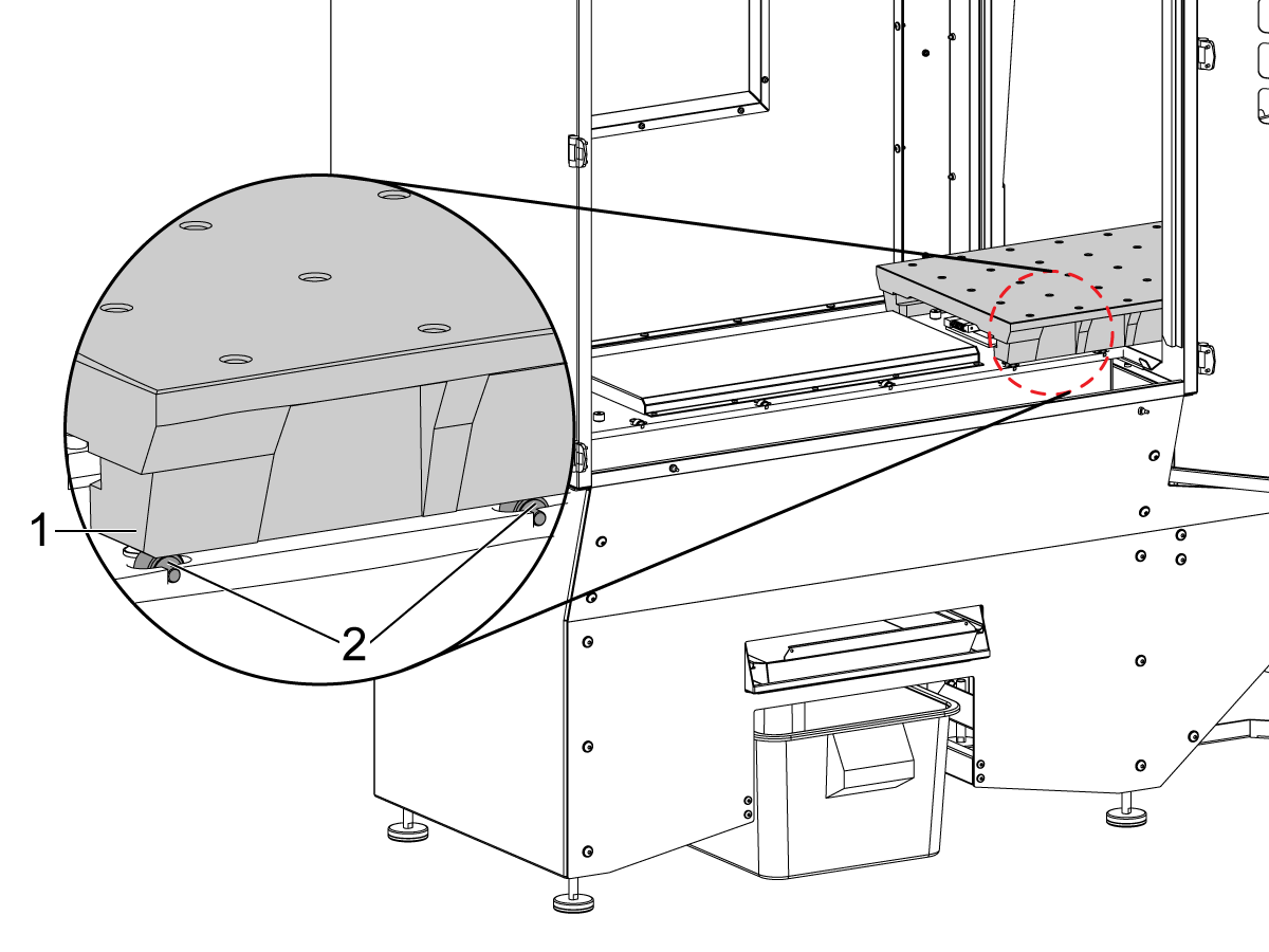
Once the loading station is leveled, manually jog the pallet [1] into the load station until it is above the first two rollers [2].

Adjust the outermost leveling feet of the load station until the rollers [2] just barely make contact with the pallet [1].

The pallet should run smoothly across all of the rollers. Once the pallet rolls smoothly across all of the rollers, touch the inner feet to the ground if they are not yet.

At this point, use the Pallet Changer Recovery page to send the pallet into the Load Station and rotate the trolley plate out so that the pallet is no longer hooked on the trolley plate and verify that the locking mechanism dowel pin latches the pallet correctly.

If the locking mechanism is not latching the pallet properly, adjust the inner feet to help adjust the locking mechanism.

Important: Do not over adjust the inner leveling feet.

Jog the pallet out of the load station and proceed to the next step.

Note: If there are still issues when sending the pallet into the load station, use the following steps to further adjust the load station alignment.

3

Follow this step if there are still issues when sending the pallet into the load station.

Remove the sheet metal cover [1] from the load station table.

Loosen the (4) bolts [2] that secure the load station table.

After slowly jog the pallet [3] into the load station, but do not unhook it from the trolley.

4

Follow this step if there are still issues when sending the pallet into the load station.

Slowly hand jog the pallet [1] off the load station so that the first two bolts [2] on the load station table are visible. Tighten the bolts [2].

Continue jogging the pallet [2] out of the load station so that the other (2) bolts [3] are showing. Tighten the bolts [3].

Once all bolts are tightened, torque them to 50 ft-lbs in a star pattern.

After the bolts are torqued, reattach the sheet metal piece that was removed in the previous step.

Align Pallet Shelves For Stations B, C, D, E, & F

1

Use the Pallet Changer Recovery page to pick up the pallet and rotate it to shelf E and hand jog the PS axis until the pallet is over the first two rollers of the load station.

The pallet should run smoothly across all of the rollers. If it does not run smoothly, use the outer and inner leveling feet to help adjust and make a smoother shelf loading process.

Use the Pallet Changer Recovery page to send the pallet into shelf E and rotate the trolley plate out so that the pallet is no longer hooked on the trolley plate and verify that the locking mechanism dowel pin latches the pallet correctly.

Note: Refer to the next step for a more in depth explanation for how the locking mechanism dowel pin should latch the pallet correctly.

If the locking mechanism is not latching the pallet properly, adjust the leveling feet to help adjust the locking mechanism.

Repeat this for shelves  F, D, C, & B in that order.

This can be an iterative process and it may be required to adjust the leveling feet back and forth when adjusting the shelves.

Note: We recommend using a roughly 6ft long level to align the station by putting the level on the rollers of the saddle and adjusting the station till the station rollers touch the level. 

2

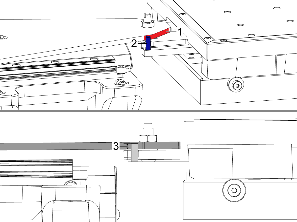
There should have been grease added to the trolley plate at [1] and on all of the dowel pins [2] in the pallet latch mechanisms, if this grease has rubbed off in shipping add more grease to these locations.

It should also be verified that the dowel pin in the pallet station latching mechanism makes at least 0.25 inches [3] of contact with the trolley plate. If this is not the case, adjust shelf leveling feet to ensure the right amount of contact is being made at each pallet shelf.

Loading Other Pallets

1

Attach the provided I-bolts to the pallet shown. Attach lifting straps or safety hooks to the I-bolts. Use a fork lift to lift the pallet and into pallet station B. 

Note: Make sure when lowering the pallet to not lower it onto the latch.

Note: The pallets can be loaded into the load station but keep an eye on the back wall when bringing in the pallet as to not hit the load station with the forklift.

Undo the I-bolts from the pallet and use the Pallet Recovery Page to move the pallet from station B to the other pallet stations. 

Repeat till all the pallets are in the pallet pool. Verify that the Pallet Scheduler Table page matches what is in the machine. 

Note: When loading the pallets into the pallet Load Station, make sure to use a proper lifting mechanism. Each pallet weighs approximately 365 lbs.

Attach Remaining Sheet Metal Walls

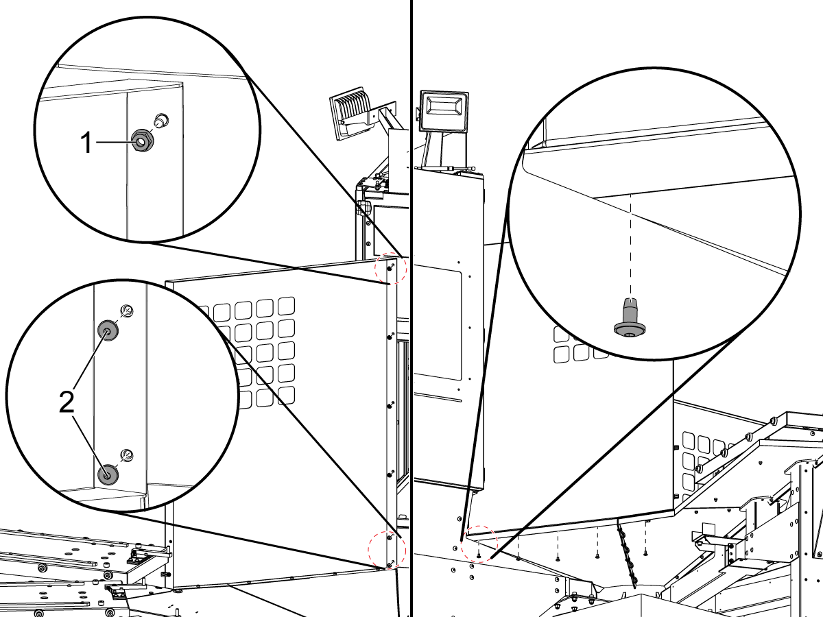
1

Install the sheet metal wall closest to the load station use the four (4) nuts [1] and two (2) bolts [2] on the vertical edge. Use the five (5) bolts to secure it underneath.

2

Install the next sheet metal wall using all bolts in the same locations as the previous wall and install the E-Stop junction box as shown.

3

Install the remaining sheet metal walls [1] and the cross bars [2] in between. Install the two removable wall rails [3] before installing the final piece of the wall. 

Setting Up Pallet Stations

1

Please refer to the PALLET POOL OPERATORS MANUAL for how to load the pallets onto the machine using the Pallet Scheduling Table.

 Important: If there is no pallet on the pallet arm then the PR will go into the station at a 4 degree offset when the pallet arm is commanded into slide to a specified station using the recovery page. It goes in at a 4 degree offset to avoid hitting the pallet locking mechanism on the pallet stations, therefore when in the recovery page and the control asks if the pallet arm is holding a pallet it MUST be answered correctly or a collision may happen between the pallet arm and the pallet locking mechanism.

2

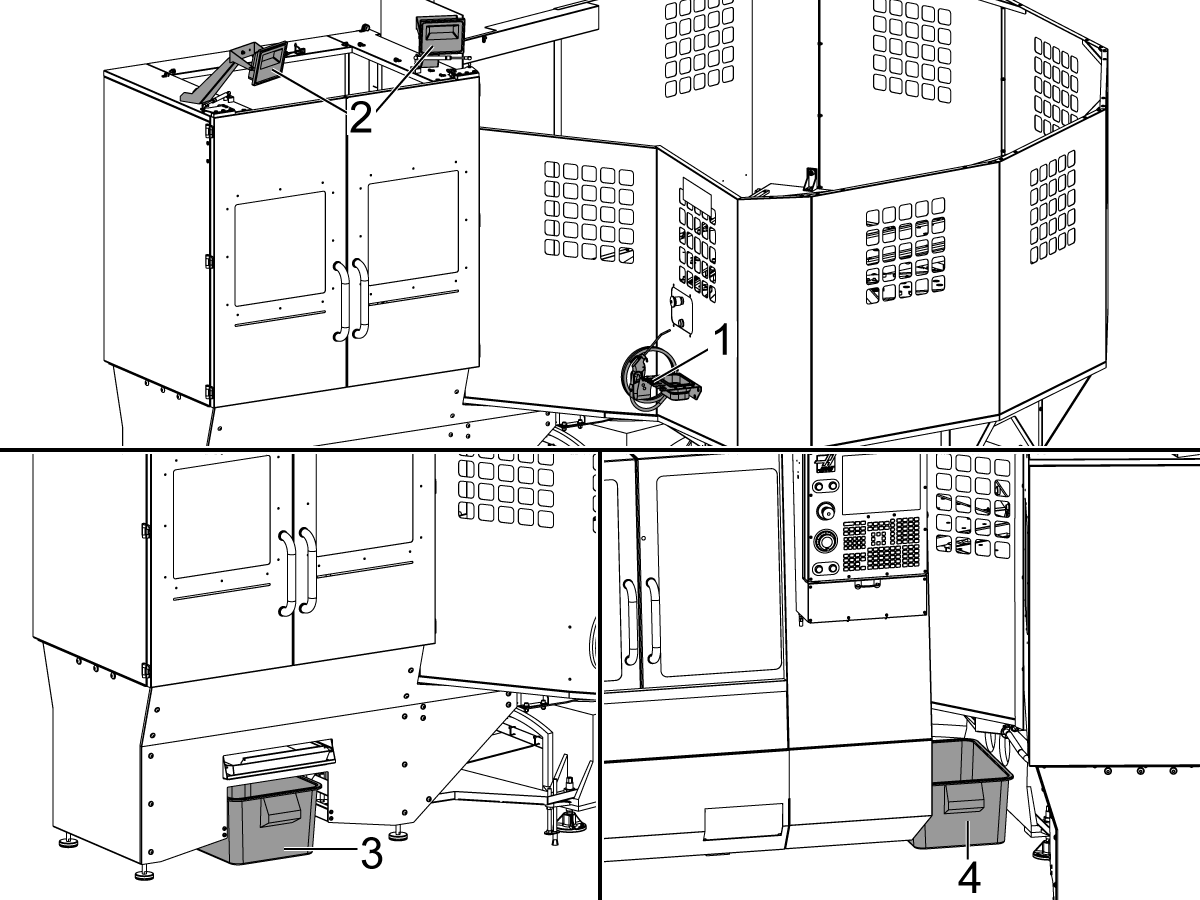
Install the tray and air gun [1] and the load station worklights [2] on the pallet pool as shown.

Place the provided totes under the Pallet Pool coolant discharge trays to catch the coolant and chips that drains from the pallets. One tote goes under the load station [3] and the other goes where the machine and pallet pool meet [4].

Empty the totes as needed. 

Test the pick up / drop off operation on the remaining stations by using the pallet pool recovery functions.  

Important: Each pallet has a max capacity of 750 lbs.

Verification

Load the pallets into all of the stations and the load station, leaving the machine receiver without a pallet. 

WARNING: Do NOT run this program unless ALL pallets are loaded into the machine and the Pallet Schedule Table matches the machine's pallets locations.

Put the machine at 25% rapid and run the following program to verify that the machine cycles through all the pallets correctly.

M50 P1 ;

M50 P2 ;

M50 P3 ;

M50 P4 ;

M50 P5 ;

M30 ;

Recently Viewed Items

You Have No Recently Viewed Items Yet

Feedback
Haas Logo

Haas Delivered Price

This price includes shipping cost, export and import duties, insurance, and any other expenses incurred during shipping to a location in France agreed with you as a buyer. No other mandatory costs can be added to the delivery of a Haas CNC Product.

KEEP UP WITH THE LATEST HAAS TIPS AND TECHNOLOGY...

Sign up now!   

HAAS TOOLING ACCEPTS THE FOLLOWING:

  • Service & Support
  • Owners
  • Request Service
  • Operator Manuals
  • Haas Parts
  • Rotary Repair Request
  • Pre-Install Guides
  • Shopping Tools
  • Build & Price a New Haas
  • Available Inventory
  • The Haas Price List
  • CNCA Financing
  • About Haas
  • Accessibility Statement
  • DNSH Statement
  • Export Compliance
  • Careers
  • Certifications & Safety
  • Contact Us
  • History
  • Terms & Conditions
  • Haas Tooling Terms & Conditions
  • Privacy
  • Warranty
  • Haas Community
  • Haas Certification Program
  • Haas Motorsports
  • Gene Haas Foundation
  • Haas Technical Education Community
  • Events
  • Join the Conversation
  • Facebook
  • X
  • Flickr
  • YouTube
  • LinkedIn
  • Instagram
  • TikTok
© 2026 Haas Automation, Inc – CNC Machine Tools

This site is protected by reCAPTCHA and the Google Privacy Policy and Terms of Service apply.

2800 Sturgis Rd., Oxnard, CA 93030
Toll Free: (888) 817-4446 / Fax: 805-278-8554