MyHaas 환영합니다,
!
Haas Tooling 게스트 주문 이력 MyHaas/HaasConnect 로그인 등록 Haas Tooling 내 계정 Order History Return History MyHaas/HaasConnect 로그아웃 환영합니다, 내 기계 최근 활동 내 견적 내 계정 내 사용자 로그아웃
담당 대리점 찾기
  1. 언어 선택
    1. English
    2. Deutsch
    3. Español - España
    4. Español - México
    5. Français
    6. Italiano
    7. Português
    8. Český
    9. Dansk
    10. Nederlands
    11. Magyar
    12. Polski
    13. Svenska
    14. Türkçe
    15. 中文
    16. Suomi
    17. Norsk
    18. الإنجليزية
    19. български
    20. Hrvatski
    21. Ελληνικά
    22. Română
    23. Slovenský
    24. Slovenščina
    25. 한국어
    26. 日本語
    27. Українська
  • 기계 Main Menu
    • Haas 수직 밀 수직 밀
      수직 밀
      수직 밀 View All
      • 수직 밀
      • VF 시리즈
      • 유니버설 기계
      • VR 시리즈
      • VP-5 프리즈매틱
      • 팔레트 교환 VMC
      • 미니밀
      • 몰드 기계
      • 고속 드릴 센터
      • 드릴/탭/밀 시리즈
      • 툴룸 밀
      • 컴팩트 밀
      • 갠트리 시리즈
      • SR 시트 라우터
      • 초대형 VMC
      • 이중 컬럼 밀
      • 제어 시뮬레이터
      • 밀 자동 공작물 적재장치
      • VMC/UMC 측면 적재 자동 공작물 적재장치
      • 컴팩트한 자동 공작물 적재장치
    • Product Image 멀티 축 솔루션
      멀티 축 솔루션
      멀티 축 솔루션 View All
      • 멀티 축 솔루션
      • Y축 선반
      • 5축 밀
    • Haas 선반 선반
      선반
      선반 View All
      • 선반
      • ST 시리즈
      • 이중 스핀들
      • 박스 웨이 시리즈
      • 툴룸 선반
      • 척커 선반
      • HAAS 봉재 이송장치 V2
      • 선반 자동 공작물 적재장치
    • Haas 수평 밀 수평 밀
      수평 밀
      수평 밀 View All
      • 수평 밀
      • 50-테이퍼
      • 40-테이퍼
    • Haas 로터리 및 인덱서 로터리 및 인덱서
      로터리 및 인덱서
      로터리 및 인덱서 View All
      • 로터리 및 인덱서
      • 회전 테이블
      • 인덱서
      • 5축 로터리
      • 초대형 로터리
    • Product Image 자동화 시스템
      자동화 시스템
      자동화 시스템 View All
      • 자동화 시스템
      • 밀 자동화
      • 선반 자동화
      • 자동화 모델
    • Haas 드릴 센터 데스크톱 기계
      데스크톱 기계
      데스크톱 기계 View All
      • 데스크톱 기계
      • 데스크톱 밀
      • 데스크톱 선반
    • Haas 공장 장비 공장 장비
      공장 장비
      공장 장비 View All
      • 공장 장비
      • 밴드쏘
      • 니형 밀
      • 표면 연마기, 2550
      • 표면 연마기, 3063
      • 레이저 절삭 기계
    • 빠른 링크 특별 시리즈  특별 시리즈 
      EU 시리즈 EU 시리즈 제작 및 가격 | 가격 목록 제작 및 가격 | 가격 목록 재고품 기계 재고품 기계 신제품 신제품 첫 CNC 첫 CNC
      공구 쇼핑
      • Haas 제품 제작 및 가격
      • 가격 목록
      • 사용 가능한 재고
      • CNCA 파이낸싱
      상담을 받고 싶으신가요?

      Haas Factory Outlet (HFO)은 고객님의 질문에 답변을 드리며 가장 좋은 선택지를 안내해 드립니다.

      CONTACT YOUR DISTRIBUTOR >
  • 옵션 Main Menu
    • Product Image 스핀들
      스핀들
      스핀들 View All
      • 스핀들
    • Product Image 공구 교환장치
      공구 교환장치
      공구 교환장치 View All
      • 공구 교환장치
    • Product Image 4 | 5축
      4 | 5축
      4 | 5축 View All
      • 4 | 5축
    • Product Image 터렛 및 라이브 툴링
      터렛 및 라이브 툴링
      터렛 및 라이브 툴링 View All
      • 터렛 및 라이브 툴링
    • Product Image 검사
      검사
      검사 View All
      • 검사
    • Haas 칩 및 절삭유 관리 칩 및 절삭유 관리
      칩 및 절삭유 관리
      칩 및 절삭유 관리 View All
      • 칩 및 절삭유 관리
    • Haas Control Haas Control
      Haas Control
      Haas Control View All
      • Haas Control
    • Product Image 제품 선택 사항
      제품 선택 사항
      제품 선택 사항 View All
      • 제품 선택 사항
    • Product Image 툴링 및 픽스처링
      툴링 및 픽스처링
      툴링 및 픽스처링 View All
      • 툴링 및 픽스처링
    • Product Image 워크홀딩
      워크홀딩
      워크홀딩 View All
      • 워크홀딩
    • Product Image 5축 솔루션
      5축 솔루션
      5축 솔루션 View All
      • 5축 솔루션
      • 5 Easy Steps to 5-Axis
    • Product Image 자동화
      자동화
      자동화 View All
      • 자동화
    • 빠른 링크 특별 시리즈  특별 시리즈 
      EU 시리즈 EU 시리즈 제작 및 가격 | 가격 목록 제작 및 가격 | 가격 목록 재고품 기계 재고품 기계 신제품 신제품 첫 CNC 첫 CNC
      공구 쇼핑
      • Haas 제품 제작 및 가격
      • 가격 목록
      • 사용 가능한 재고
      • CNCA 파이낸싱
      상담을 받고 싶으신가요?

      Haas Factory Outlet (HFO)은 고객님의 질문에 답변을 드리며 가장 좋은 선택지를 안내해 드립니다.

      CONTACT YOUR DISTRIBUTOR >
  • Why Haas Main Menu
      Haas의 차이를 알아보세요
    • Haas여야만 하는 이유
    • MyHaas
    • 교육 커뮤니티
    • Industry 4.0
    • Haas 인증
    • 고객 사용후기
  • 서비스 Main Menu
      Haas Service 에 오신 것을 환영합니다
      서비스 홈 조작자 설명서 방법 절차 문제해결 가이드 예방적 유지관리 Haas 부품 Haas Tooling 동영상
  • 동영상 Main Menu
×

검색 결과

Web Pages

Images

    • <
    • 1
    • >
MyHaas 환영합니다,
!
Haas Tooling 게스트 주문 이력 MyHaas/HaasConnect 로그인 등록 Haas Tooling 내 계정 Order History Return History MyHaas/HaasConnect 로그아웃 환영합니다, 내 기계 최근 활동 내 견적 내 계정 내 사용자 로그아웃
담당 대리점 찾기
  1. 언어 선택
    1. English
    2. Deutsch
    3. Español - España
    4. Español - México
    5. Français
    6. Italiano
    7. Português
    8. Český
    9. Dansk
    10. Nederlands
    11. Magyar
    12. Polski
    13. Svenska
    14. Türkçe
    15. 中文
    16. Suomi
    17. Norsk
    18. الإنجليزية
    19. български
    20. Hrvatski
    21. Ελληνικά
    22. Română
    23. Slovenský
    24. Slovenščina
    25. 한국어
    26. 日本語
    27. Українська
×

검색 결과

Web Pages

Images

    • <
    • 1
    • >

UMC C-Axis Rotary Encoder Ring - Replacement - AD0497

서비스 홈 방법 절차 UMC C축 로터리 인코더 링 - 교체 - AD0497

UMC C축 로터리 인코더 링 - 교체 - AD0497

- 섹션으로 건너뛰기 - Back to Top

10.2 UMC ROTARY ENCODER RING - REPLACEMENT

Recently Updated Last updated: 06/13/2025

UMC C-Axis Rotary Encoder Ring - Replacement


AD0497

Revision A 06/2025

Introduction

This procedure details the replacement of the 3" C-Axis Encoder on all UMC machines and the 3" B-Axis Encoder on UMC -500/SS machines only.

Laser calibration is required to update the compensation table for the corresponding rotary axis following the encoder replacement. 

This document applies to the following Service Kits:

  • 93-3923  ENCDR NON-CONT KIT 3"ID SER HI-RES

Used on B & C-Axis:

  • UMC-500/SS

Used on C-Axis:

  • UMC-750/SS
  • UMC-1000/SS
  • UMC-1250/SS
  • UMC-1500-DUO/SS

Tools Required:

  • 99-2130 ANTI-OXIDANT COMPOUND ELECTRICAL
  • 99-2147 DIELECTRIC GREASE PACK SUPER LUBE
  • 0.008" Mylar Shim

C-Axis Encoder Ring Replacement

1

: Warning: Only certified service personnel should perform this procedure. Reorientation of Z-pulse or Trip-Flag will require laser calibration to populate rotary compensation tables with new, correct, values.

Zero-return all Axis.

Press [EMERGENCY STOP].

2

Handle jog B to +120°.

Remove the C-Axis bottom cover.

3

Press [SETTING].

Navigate to the Rotaty tab.

Un-Check the 4th Axis.

4

Press [DIAGNOSTIC].

Navigate to Parameters > Factory.

Set 7.083 C-Axis Linear Scale Enabled to "Scale Disabled".

Power off the machine.

5

Uninstall the encoder read-head [1] by disconnecting the encoder cable [2] and removing the bolts and washers.

6

Note the Z-Pulse orientation before removing the encoder ring hub.

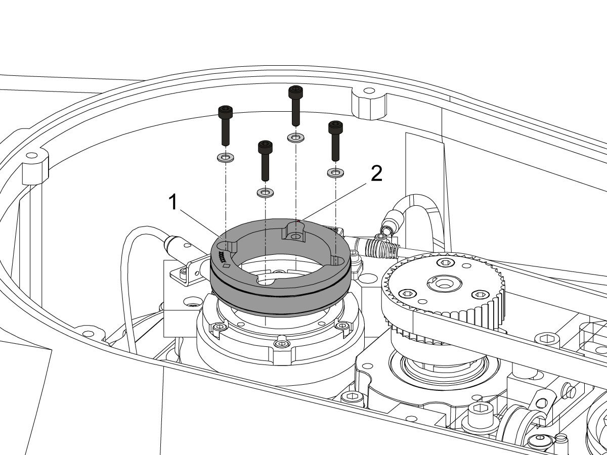
Uninstall the encoder ring hub [1] by removing the screws and washers mounting the encoder ring hub to the taper-lock. 

7

Mount and loosely install the encoder ring hub [1] from the service kit with the provided hardware, SHCS 10-32 X 3/4 (x4) and WASHER #10 FLAT (x4).

Verify the Z-Pulse is in the same location as the ring that was uninstalled. 

 Note: Do not torque mounting screws yet.

8

Turn on the machine.

Zero return all axis.

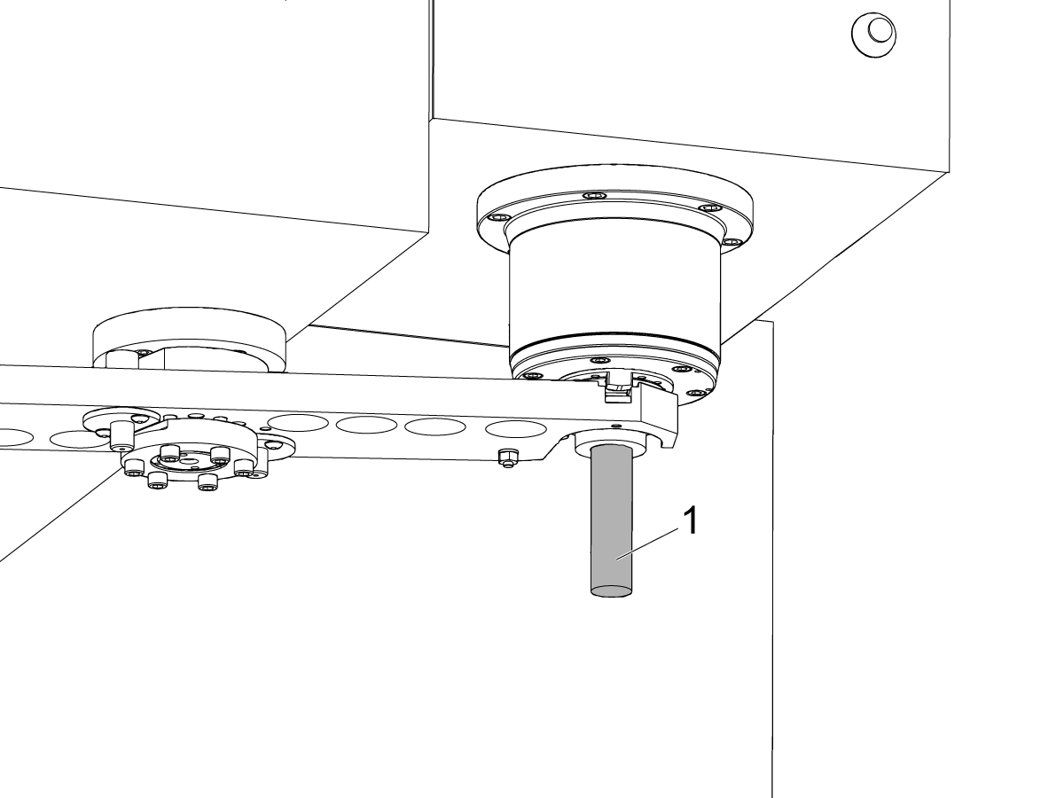
 Warning: Do not place the Mag Base anywhere near the Encoder.

Check and document the runout on the OD of the scale encoder ring hub using the upper-most diameter, as shown.

Adjust as necessary. TIR must be 0.0005" or less.

Torque the 4 bolts of the encoder ring hub to 30 in-lbf in the star pattern.

After torquing, double check the runout to verify the ring hub has not shifted.

9

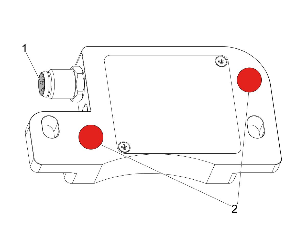
Clean the back surface of the encoder read-head and the mounting surface.

Add a small amount of silicone dielectric grease to encoder cable connection [1]. Grease should be a thin layer, but cover all the pins.

Apply two small drops of anti-oxidant (99-2130) to the mounting surface on the read head in the locations shown [2].

10

Connect the encoder cable [4] to the encoder read-head.

Insert cable by carefully lining up electrical pins with cable connector.

Install the encoder read-head [1] from the service kit with the provided hardware,  SHCS 8-32 x 1/2 bolts (x2) [2] and Washer .17ID x .4OD (2x) [3].

 Note: Do not torque mounting screws yet.

11

Set the gap between the scale ring and read-head as shown [1] using the appropriate mylar shim (0.008").

 Note: Do not use a metal shim.

Starting on the left side of the read-head [2], torque the two read-head mounting bolts to 20 in-lbf.

After torquing, double check the gap with the shim to verify the read-head has not shifted.

12

Reinstall the C-Axis bottom cover being sure no tools, shims, etc. have been left in the casting.

13

Press [SETTING].

Navigate to the Rotaty tab.

Check the 4th Axis.

Rotate the B-Axis back to zero when done.

14

Press [DIAGNOSTIC].

Navigate to Parameters > Configuration > Axis > B > Travel Limits.

Change: 6.108 B-Axis Positive Travel Limit from 180 to 110.

15

Press [DIAGNOSTIC].

Navigate to Parameters > Factory.

Set 7.083 C-Axis Linear Scale Enabled to "Scale Linear".

Power cycle the machine.

16

Zero-Return the C-Axis.

Zero-Return All Axis.

Set new Tool Change offset by following the UMC - X and Y Axes - Tool Change Offsets and the Side-Mount Tool Changer - Z-Axis Tool Change Offset - NGC procedures.

17

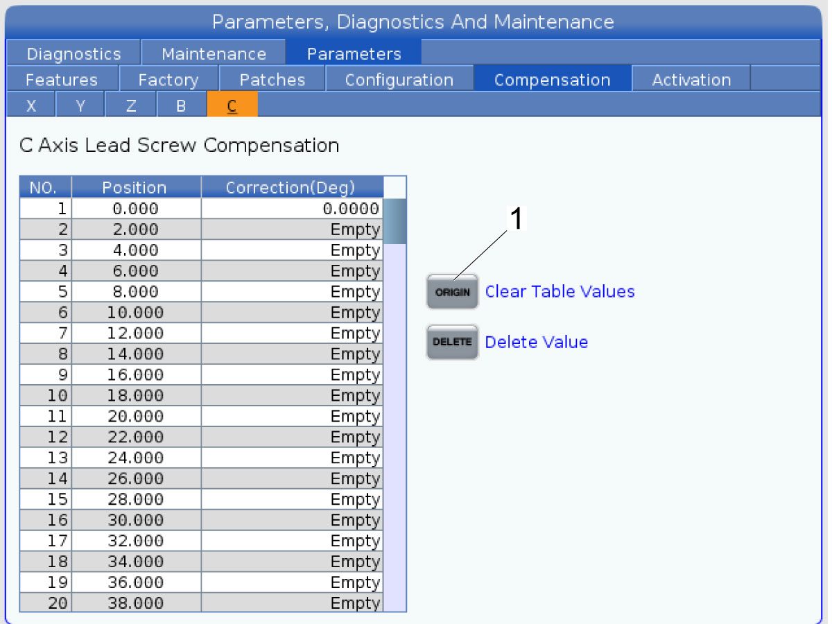
Clear the Compensation table for the C-Axis.

Press [DIAGNOSTIC].

Navigate to Parameters > Compensation > C.

Press [ORIGIN].

To update compensation table values for the C-Axis a laser calibration is required. The calculated compensation values will then be entered into the C-Axis Compensation Table.

B-Axis Encoder Ring Replacement

 Note: These step apply only to the UMC-500/SS B-Axis.

1

: Warning: Only certified service personnel should perform this procedure. Reorientation of Z-pulse or Trip-Flag will require laser calibration to populate rotary compensation tables with new, correct, values.

Zero-return all Axis.

Press [EMERGENCY STOP].

2

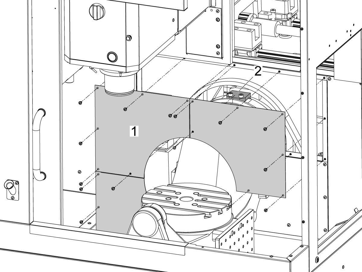
Remove the bulkhead sheet metal [1] to access the B-Axis hard stop [2]. 

3

Rotate the B-Axis approximately 100 degrees, or until there is enough room to access the hard stop [1].

Remove the B-Axis hard stop [1].

4

Remove the two rear sheet metal panels [1] to access the B-Axis components.

5

Insert a service key and enter service mode.

Press [DIAGNOSTIC].

Navigate to Parameters > Configuration > Axis > B > Travel Limits.

Change: 6.108 B-Axis Positive Travel Limit from 110 to 365.

6

Handle jog B to +180°.

Remove the C-Axis bottom cover.

7

Press [DIAGNOSTIC].

Navigate to Parameters > Factory.

Set 6.083 B-Axis Linear Scale Enabled to "Scale Disabled".

Power off the machine.

8

Disconnect all of the cables and hoses [1] running to the C-Axis through the B-Axis encoder ring. 

 Note: Mark the cables and hose to make reconnecting them easier later in this procedure. 

Remove the corrugated conduit [2].

9

Uninstall the encoder read-head [1] by disconnecting the encoder cable [2] and removing the bolts and washers.

10

Note the Z-Pulse orientation before removing the encoder ring hub.

Uninstall the encoder ring hub [1] by removing the screws and washers mounting the encoder ring hub to the taper-lock. 

11

Mount and loosely install the encoder ring hub [1] from the service kit with the provided hardware, SHCS 10-32 X 3/4 (x4) and WASHER #10 FLAT (x4).

Verify the Z-Pulse is in the same location as the ring that was uninstalled. 

 Note: If the Z-Pulse is in the wrong location the B-Axis will not zero return correctly and can damage the cables and hoses.

 Note: Do not torque mounting screws yet.

12

Route all of the cables and hoses [1] for the C-Axis through the corrugated conduit [2] and through the B-Axis encoder ring. 

Reconnect all of the cables and hoses to their original locations in the C-Axis.

13

Turn on the machine.

Zero return all axis.

 Note: The B-Axis should zero return in the Clockwise direction.

 Warning: Do not place the Mag Base anywhere near the Encoder.

Check and document the runout on the OD of the scale encoder ring hub using the upper-most diameter, as shown.

Adjust as necessary. TIR must be 0.0005" or less.

Torque the 4 bolts of the encoder ring hub to 30 in-lbf in the star pattern.

After torquing, double check the runout to verify the ring hub has not shifted.

14

Clean the back surface of the encoder read-head and the mounting surface.

Add a small amount of silicone dielectric grease to encoder cable connection [1]. Grease should be a thin layer, but cover all the pins.

Apply two small drops of anti-oxidant (99-2130) to the mounting surface on the read head in the locations shown [2].

15

Connect the encoder cable [1] to the encoder read-head.

Insert cable by carefully lining up electrical pins with cable connector.

Install the encoder read-head [2] from the service kit with the provided hardware,  SHCS 8-32 x 1/2 bolts (x2) [4] and Washer .17ID x .4OD (2x) [3].

 Note: Do not torque mounting screws yet.

16

Set the gap between the scale ring and read-head as shown [1] using the appropriate mylar shim (0.008").

 Note: Do not use a metal shim.

Starting on the left side of the read-head [2], torque the two read-head mounting bolts to 20 in-lbf.

After torquing, double check the gap with the shim to verify the read-head has not shifted.

17

Reinstall the C-Axis bottom cover being sure no tools, shims, etc. have been left in the casting.

 Note: You will have to set a new tool change offset and update compensation table values for the B-Axis. This will require laser calibration.

18

Rotate the B-Axis to the same position when the hard stop was removed. 

Install the B-Axis hard stop [1].

19

Press [DIAGNOSTIC].

Navigate to Parameters > Configuration > Axis > B > Travel Limits.

Change: 6.108 B-Axis Positive Travel Limit from 365 to 110.

Rotate the B-Axis back to zero when done.

20

Press [DIAGNOSTIC].

Navigate to Parameters > Factory.

Set 6.083 B-Axis Linear Scale Enabled to "Scale Linear".

Power cycle the machine.

21

Zero-Return the B-Axis.

Zero-Return All Axis.

Set new Tool Change offset by following the UMC - X and Y Axes - Tool Change Offsets and the Side-Mount Tool Changer - Z-Axis Tool Change Offset - NGC procedures.

22

Install the bulkhead sheet metal [1] once the B-Axis hard stop [2] has been installed. 

23

Install the two rear sheet metal panels [1].

24

Clear the Compensation table for the B-Axis.

Press [DIAGNOSTIC].

Navigate to Parameters > Compensation > B.

Press [ORIGIN].

To update compensation table values for the B-Axis a laser calibration is required. The calculated compensation values will then be entered into the B-Axis Compensation Table.

Recently Viewed Items

You Have No Recently Viewed Items Yet

피드백
Haas Logo

美元价格不包括关税、报关费用、保险费、增值税及运费。
USD prices DO NOT include customs duty, customs fees, insurance, VAT, or freight.

人民币价格包含关税、报关费用、货运保险和增值税, 但不包括运费。
CNY prices include customs duty, customs fees, insurance, and VAT. DOES NOT include freight.

Haas 납품 가격

이 가격에는 구매자인 귀사와 합의된 프랑스 국내 지역으로 배송 중에 발생하는 배송 비용, 수출 및 수입 관세, 보험료 및 그 외 모든 비용이 포함됩니다. Haas CNC 제품의 납품에는 그 외 의무 비용이 추가되지 않습니다.

최신 HAAS 팁 및 기술을 확인해 보세요…

지금 가입하기!   

HAAS TOOLING ACCEPTS THE FOLLOWING:

  • 서비스 및 지원
  • 소유자
  • 서비스 요청
  • 조작자 설명서
  • Haas 부품
  • 로터리 수리 요청
  • 사전 설치 가이드
  • 공구 쇼핑
  • Haas 신규 제품 제작 및 가격
  • 사용 가능한 재고
  • Haas 가격 목록
  • CNCA 파이낸싱
  • Haas 소개
  • DNSH 문
  • 채용
  • 인증 및 안전
  • 연락처
  • 이력
  • 이용약관
  • Haas Tooling 이용 약관
  • 개인정보 보호
  • 보증
  • Haas 커뮤니티
  • Haas 인증 프로그램
  • Haas Motorsports
  • Gene Haas 재단
  • Haas 기술 교육 커뮤니티
  • 이벤트
  • SNS 참여
  • Facebook
  • X
  • Flickr
  • YouTube
  • LinkedIn
  • Instagram
  • TikTok
© 2025 Haas Automation Inc. - CNC 공작 기계

This site is protected by reCAPTCHA and the Google Privacy Policy and Terms of Service apply.

2800 Sturgis Rd., Oxnard, CA 93030 / Toll Free: 800-331-6746
Phone: 805-278-1800 / Fax: 805-278-2255