Moj Haas Dobrodošli,
!
Haas Tooling MyHaas/HaasConnect Vpis Registrirajte Haas Tooling MyHaas/HaasConnect Izpis Dobrodošli, Moji stroji Zadnja dejavnost Moje ponudbe Moj račun Moji uporabniki Izpis
Poiščite distributerja
  1. Izberite jezik
    1. English
    2. Deutsch
    3. Español - ES
    4. Español - MX
    5. Français
    6. Italiano
    7. Português
    8. Český
    9. Dansk
    10. Nederlands
    11. Magyar
    12. Polski
    13. Svenska
    14. Türkçe
    15. 中文
    16. Suomi
    17. Norsk
    18. الإنجليزية
    19. български
    20. Hrvatski
    21. Ελληνικά
    22. Română
    23. Slovenský
    24. Slovenščina
    25. 한국어
    26. 日本語
    27. Українська
  • stroji Main Menu
    • Vertikalni rezkarji
      Vertikalni rezkarji
      Vertikalni rezkarji View All
      • Vertikalni rezkarji
      • v nizu
      • Univerzalni stroji
      • Serija VF
      • VP-5 prizmatično
      • VMC z menjavo palet
      • Rezkalni stroji Mini Mills
      • Kalupni stroji
      • Visokohitrostni vrtalni centri
      • Serija Drill/Tap/Mill
      • Rezkarji Toolroom Mill
      • Pocket Mill
      • Kompaktni rezkarji
      • Serija Gantry
      • SR usmerjevalniki pločevine
      • Izjemno velik vertikalni obdelovalni center (VMC)
      • Rezkarji z dvema stebroma
      • Stroji za obdelovanje z uporabo 3+2-osnega pozicioniranja
    • Večosne rešitve
      Večosne rešitve
      Večosne rešitve View All
      • Večosne rešitve
      • Stružnice z Y-osjo
      • 5-osni rezkarji
    • Stružnice
      Stružnice
      Stružnice View All
      • Stružnice
      • Serija ST
      • Dvojno-vreteno
      • Serija drsnih vodil
      • Stružnice Toolroom Lathe
      • Stružnica Chucker
      • Žepna stružnica
      • Podajalec palic Haas
    • Horizontalni rezkarji
      Horizontalni rezkarji
      Horizontalni rezkarji View All
      • Horizontalni rezkarji
      • 50-konusni
      • 40-konusni
    • Rotacijske mize in indekserji
      Rotacijske mize in indekserji
      Rotacijske mize in indekserji View All
      • Rotacijske mize in indekserji
      • Vrtljive mize
      • Indekserji
      • 5-osne vrtljive mize
      • Zelo velike vrtljive mize
    • Avtomatizirani sistemi
      Avtomatizirani sistemi
      Avtomatizirani sistemi View All
      • Avtomatizirani sistemi
      • Avtomatizacija rezkarja
      • Avtomatizacija stružnice
      • Avtomatske naprave za nalaganje kosov
      • Modeli avtomatizacije
    • Namizni stroji
      Namizni stroji
      Namizni stroji View All
      • Namizni stroji
      • Namizni rezkar
      • Namizna stružnica
      • Simulator krmilja, standardni
      • Simulator krmilja, Premium
    • Oprema za delavnice
      Oprema za delavnice
      Oprema za delavnice View All
      • Oprema za delavnice
      • Rezkar za koleno
      • Haas ročne stružnice
      • Žage Haas
    • Stroji za proizvodnjo
      Stroji za proizvodnjo
      Stroji za proizvodnjo View All
      • Stroji za proizvodnjo
      • Laserski rezalni stroj
      • CNC stiskalnice
    • HITRE POVEZAVE Posebna serija  Posebna serija 
      EU SERIJA EU SERIJA IZDELAVA IN CENA | CENIK IZDELAVA IN CENA | CENIK Stroji na zalogi Stroji na zalogi KAJ JE NOVEGA? KAJ JE NOVEGA? VAŠ PRVI CNC VAŠ PRVI CNC
      ORODJA ZA NAKUPOVANJE
      • Sestavi in preveri ceno Haas
      • Cenik
      • Razpoložljiv inventar
      • Financiranje CNCA
      SE ŽELITE S KOM POGOVORITI?

      Tovarniška izpostava Haas (HFO) lahko odgovori na vaša vprašanja in vam predstavi vaše najboljše možnosti.

      CONTACT YOUR DISTRIBUTOR >
  • Možnosti Main Menu
    • The Haas Control Paketi možne vrednosti
      Paketi možne vrednosti
      Paketi možne vrednosti View All
      • Paketi možne vrednosti
    • Product Image Vretena
      Vretena
      Vretena View All
      • Vretena
    • Product Image Menjalci orodja
      Menjalci orodja
      Menjalci orodja View All
      • Menjalci orodja
    • Product Image 4. | 5. os
      4. | 5. os
      4. | 5. os View All
      • 4. | 5. os
    • Product Image Revolverji in gnana orodja
      Revolverji in gnana orodja
      Revolverji in gnana orodja View All
      • Revolverji in gnana orodja
    • Product Image Merjenje s sondo
      Merjenje s sondo
      Merjenje s sondo View All
      • Merjenje s sondo
    • Obvladovanje odrezkov in emulzije Haas Obvladovanje odrezkov in emulzije
      Obvladovanje odrezkov in emulzije
      Obvladovanje odrezkov in emulzije View All
      • Obvladovanje odrezkov in emulzije
    • Krmilje Haas Krmilje Haas
      Krmilje Haas
      Krmilje Haas View All
      • Krmilje Haas
    • Product Image Opcije izdelka
      Opcije izdelka
      Opcije izdelka View All
      • Opcije izdelka
    • Product Image Orodje in vpenjanje
      Orodje in vpenjanje
      Orodje in vpenjanje View All
      • Orodje in vpenjanje
    • Product Image Vpenjanje obdelovanca
      Vpenjanje obdelovanca
      Vpenjanje obdelovanca View All
      • Vpenjanje obdelovanca
    • Product Image 5-osne rešitve
      5-osne rešitve
      5-osne rešitve View All
      • 5-osne rešitve
      • 5 Easy Steps to 5-Axis
    • Product Image Avtomatizacija
      Avtomatizacija
      Avtomatizacija View All
      • Avtomatizacija
    • HITRE POVEZAVE Posebna serija  Posebna serija 
      EU SERIJA EU SERIJA IZDELAVA IN CENA | CENIK IZDELAVA IN CENA | CENIK Stroji na zalogi Stroji na zalogi KAJ JE NOVEGA? KAJ JE NOVEGA? VAŠ PRVI CNC VAŠ PRVI CNC
      ORODJA ZA NAKUPOVANJE
      • Sestavi in preveri ceno Haas
      • Cenik
      • Razpoložljiv inventar
      • Financiranje CNCA
      SE ŽELITE S KOM POGOVORITI?

      Tovarniška izpostava Haas (HFO) lahko odgovori na vaša vprašanja in vam predstavi vaše najboljše možnosti.

      CONTACT YOUR DISTRIBUTOR >
  • Why Haas Main Menu
      Spoznajte Haasovo razliko
    • Zakaj Haas?
    • MyHaas
    • Skupnost za izobraževanje
    • Industrija 4.0
    • Certifikat Haas
    • Pričevanja strank
  • Servis Main Menu
      Dobrodošli v Haas Service
      DOMAČA STRAN ZA SERVIS Priročniki za operaterja Postopki z navodili Navodila za odpravljanje napak preventivno vzdrževanje Deli Haas Haas Tooling Videoposnetki
  • Videoposnetki Main Menu
Moj Haas Dobrodošli,
!
Haas Tooling MyHaas/HaasConnect Vpis Registrirajte Haas Tooling MyHaas/HaasConnect Izpis Dobrodošli, Moji stroji Zadnja dejavnost Moje ponudbe Moj račun Moji uporabniki Izpis
Poiščite distributerja
  1. Izberite jezik
    1. English
    2. Deutsch
    3. Español - ES
    4. Español - MX
    5. Français
    6. Italiano
    7. Português
    8. Český
    9. Dansk
    10. Nederlands
    11. Magyar
    12. Polski
    13. Svenska
    14. Türkçe
    15. 中文
    16. Suomi
    17. Norsk
    18. الإنجليزية
    19. български
    20. Hrvatski
    21. Ελληνικά
    22. Română
    23. Slovenský
    24. Slovenščina
    25. 한국어
    26. 日本語
    27. Українська
×

Iskalni rezultati

Web Pages

Images

    • <
    • 1
    • >

3 - Lathe - Installation

Lathe - Interactive Service Manual


  • 1 - Lathe - Introduction
  • 2 - Lathe - Specifications
  • 3 - Lathe - Installation
  • 1 – Stružnica – Uvod
  • 2 – Stružnica – Specifikacije
  • 3 – Stružnica – Namestitev
  • 4 – Stružnica – Vreteno
  • 5 – Stružnica – C-os
  • 6 – Stružnica – Sklop indekserja revolverja
  • 7 – Stružnica – Gnano orodje
  • 8 – Stružnica – Hidravlična pogonska enota (HPU)
  • 9 – Stružnica – Konjiček
  • 10 – Stružnica – Protivreteno
  • 11 – Stružnica – Merjenje
  • 12 – Stružnica – Odjemalec kosov
  • 13 – Stružnica – Gibanje osi
  • 14 – Stružnica – Mazalni sistemi
  • 15 – Stružnica – Električno krmiljenje
  • 16 – Stružnica – Odstranjevanje odrezkov in emulzije
  • 17- Vpenjanje obdelovancev pri struženju
  • 18 – Stružnica – Avtomatska vrata
  • 19 – Stružnica – Zaprt sistem
  • 20 – Stružnica – Vzdrževanje
  • 21 – Stružnica – Aplikacije
  • 22 – Stružnica – Avtomatski nalagalni sistem (APL)
  • 23 – Stružnica – Podajalec palic Haas
  • 24 – Stružnica – Robotski paket Haas
  • 25 - Lathe - CAN Bus Systems

Go To :

  • 3.1 Stružnica – Namestitev
  • 3.2 Sidranje

3.1 Stružnica – Namestitev

Recently Updated

ST stružnica – Namestitev – NGC


Revizija E - 06/2026

Uvod

Ta postopek vam pokaže, kako namestiti ST stružnico.

Potrebna orodja:

  • Raven natančnosti strojnika, 0,0005" Divizije
  • T-2181A CNC orodje za dvojno izravnavo 

Če želite ugotoviti, ali imate stroj s ponovnim zagonom, glejte: Stroj serije ST - Identifikacija

Izravnava strojne opreme vijakov

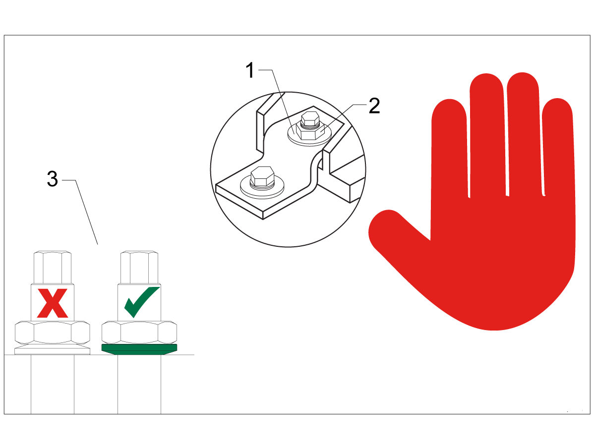
Note: The washers [1] and nuts [2] are installed during shipping and should be saved for installation and not be discarded.

Note: The washer orientation [3] is important.  The conical part of the washer should be against the casting,  see illustration.

Odstranite zaviralnik rje

To safely and effectively remove rust inhibitor from way covers and other non-painted surfaces:

Initial Scraping

  • Use a plastic scraper to remove the bulk of the rust inhibitor.
  • Avoid using metal tools to prevent scratching or damaging the surface.

 Important: Do not use scotch-brite or metal scrapers, these will scratch the way covers.

Chemical Cleaning

  • Spray the affected areas with a heavy-duty citrus cleaner or Simple Green.
  • Ensure full coverage of all non-painted surfaces coated with rust inhibitor.

Soak Time

  • Allow the cleaner to soak for several minutes to loosen remaining residue.

Wipe Down

  • Use a clean shop towel to thoroughly wipe off the softened rust inhibitor.

Rust Proofing

  • Apply mineral spirits or WD-40 to all exposed metal surfaces to prevent future rust formation.

Important: Always wear gloves and eye protection when handling chemical cleaners. Dispose of used towels and cleaning agents according to local environmental regulations.

 Important: To avoid any contamination of the way cover seals with the sticky residue. Do not move any of the axes until all the rust inhibitor has been removed.

Rust Inhibitor - Safety Data Sheet (SDS)

Zračna povezava

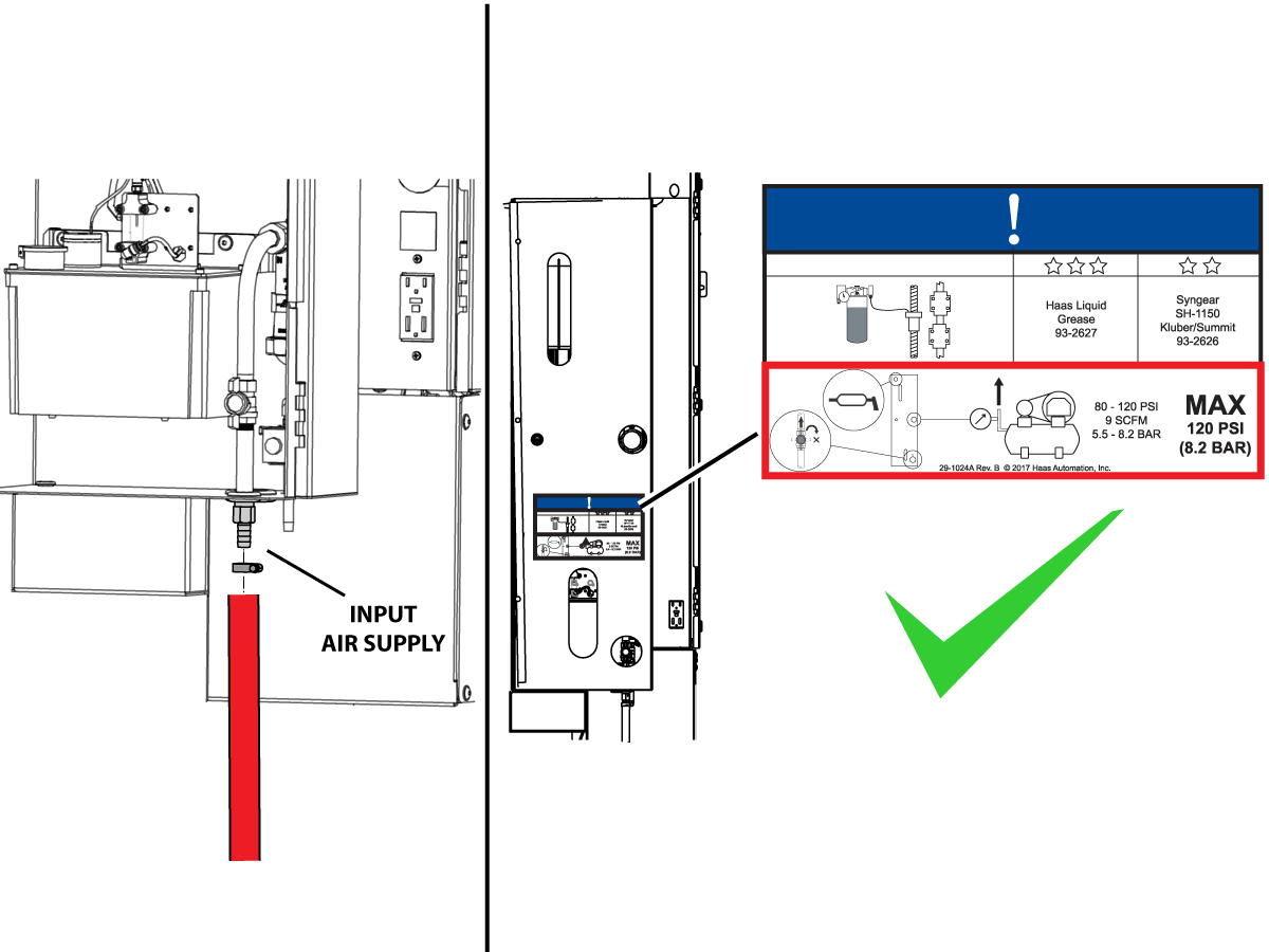
Connect the air supply at the lube panel.

 Note: For air requirements refer to the decal that is located on the lube cabinet door.

Follow the Air Gun and Hose Installation procedure to install or replace the Air Gun.

 Note: Some installation kits will come with a spare air gun assembly.

Električna napeljava

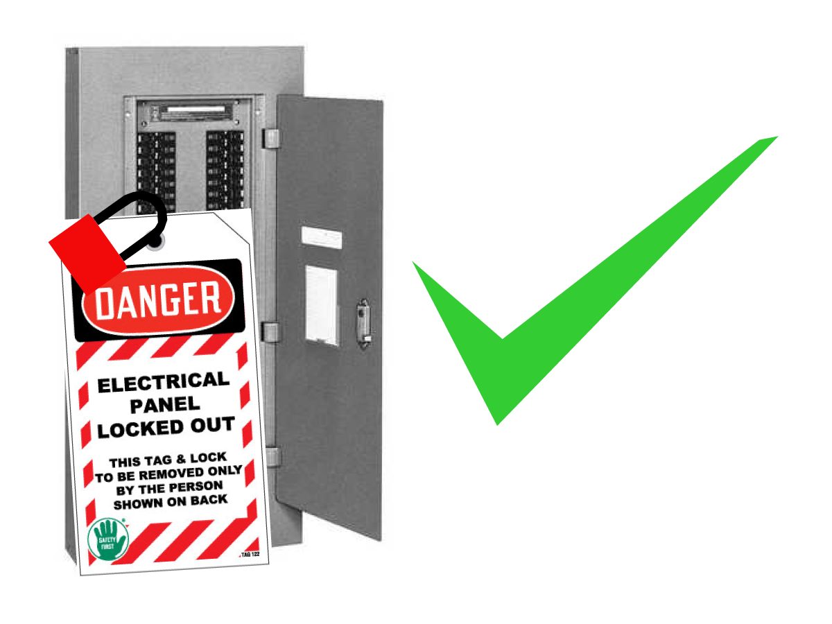
 DANGER: Working with the electrical services required for CNC machines is extremely hazardous and can result in serious injury or death.

Before connecting line wires to the CNC:

  • Turn off all power to the machine at the source.
  • Perform a Lockout-Tagout (LOTO) procedure to ensure the power remains off during service.
  • Verify that power has been disconnected by using an AC voltage detector on all incoming lines.

If you are uncertain about how to safely disconnect power or perform LOTO procedures:

  • Do not proceed.
  • Contact qualified personnel or obtain appropriate assistance before continuing.

Failure to follow these precautions may result in electrical shock, equipment damage, or fatal injury.

1

Initial Control Inspection

Danger: At this point, there should be no electrical connection to the machine. Electrical panel must be closed and secured. When main switch is on, there is HIGH VOLTAGE throughout the electrical panel (including the circuit boards and logic circuits) and some components operate at high temperatures. Therefore, exercise extreme caution when working in the panel.

  • Set the main breaker switch at the upper right of the electrical panel on the back of the machine to OFF.
  • Using a screwdriver, unlock the two latches on the panel door, unlock the cabinet with the key and open the door.
  • Take sufficient time to check all the components and connectors associated with the circuit boards. Look for any cables that have become disconnected, look for any signs damage and loose parts in the bottom of the panel box. If there are any signs that the machine was mishandled, call the factory before proceeding.

2

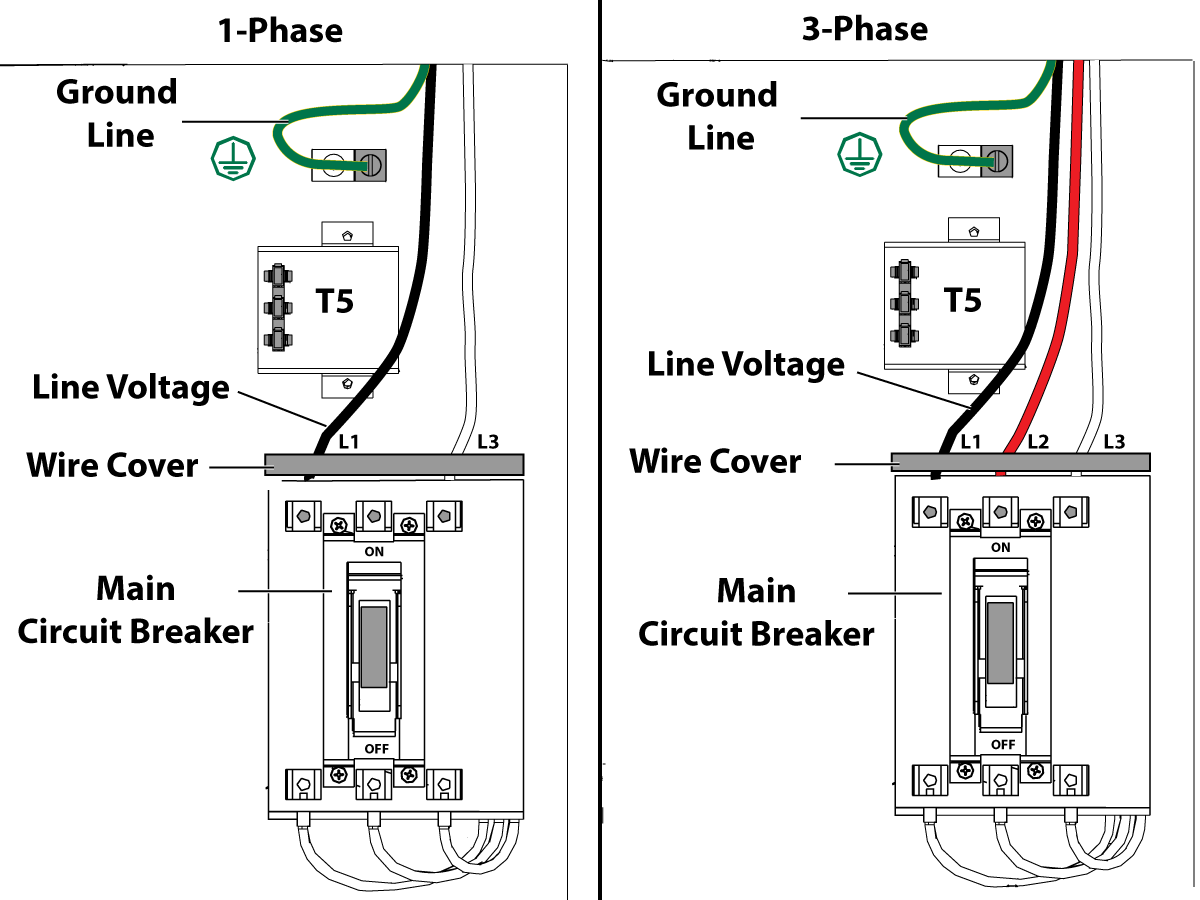
1-Phase Machines: Insert each power lead into the wire cover.  Connect the two power leads to L1 and L3 terminals on top of the main circuit breaker.

3-Phase Machines: Insert each power lead into the wire cover.  Connect the three power leads to L1, L2 and L3 terminals on top of the main circuit breaker.

Connect the separate ground line to the ground bus to the left of the terminals.

For 3-phase machines, check to see what type of power configuration is supplying the machine. Take voltage measurements of each power lead to ground line. Then refer to RD0084 - Input Power Configurations to determine which power lead should be connected to the L1 terminal based of the voltage readings and power configuration.

Refer to Haas Main Circuit Breaker - Torque Specifications for what value to torque the circuit breaker power leads.

 Note: Make sure that the leads actually go into the terminal-block clamps . (A poor connection will cause the machine to run intermittently or have other problems, such as servo overloads.) To check, simply pull on the wires after the screws are tightened.

3

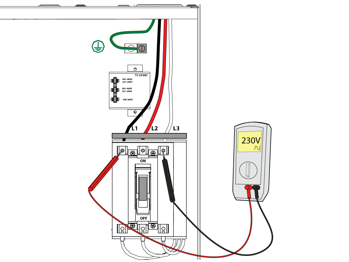
After the line voltage is connected to the machine, make sure that main circuit breaker (at top-right of rear cabinet) is OFF . Remove the Lockout / Tagout and Turn ON the power at the source. Using a digital voltmeter and appropriate safety procedures: 

1-Phase Machines: Measure the AC voltage across L1 & L3 at the main circuit breaker.  The AC voltage must be between 220 - 250 volts .
Note: Lower or higher than this voltage can generate low/high voltage alarms.

3-Phase Machines : Measure the AC voltage between all three pair phases at the main circuit breaker. 

The AC voltage must be between 195 and 260 volts (360 and 480 volts for high voltage option).

SMinimill - Reboot: The AC voltage must be between 198 and 242 volts for machines without a high voltage transformer.  Refer to the Minimill/SMinimill - Identification document.

 Note: Wide voltage fluctuations are common in many industrial areas; minimum and maximum voltage supplied to a machine while it is in operation must be known. U.S. National Electrical Code specifies that machines should operate with a variation of +5% to -5% around an average supply voltage. If problems with line voltage occur, or low line voltage is suspected, an external transformer may be used. If you suspect voltage problems, voltage should be checked every hour or two during a typical day to be sure it does not fluctuate more than +5% or -5% from an average.

4

Important: With the main circuit breaker turned OFF.

Check the transformer taps at the bottom-right corner of the rear cabinet.

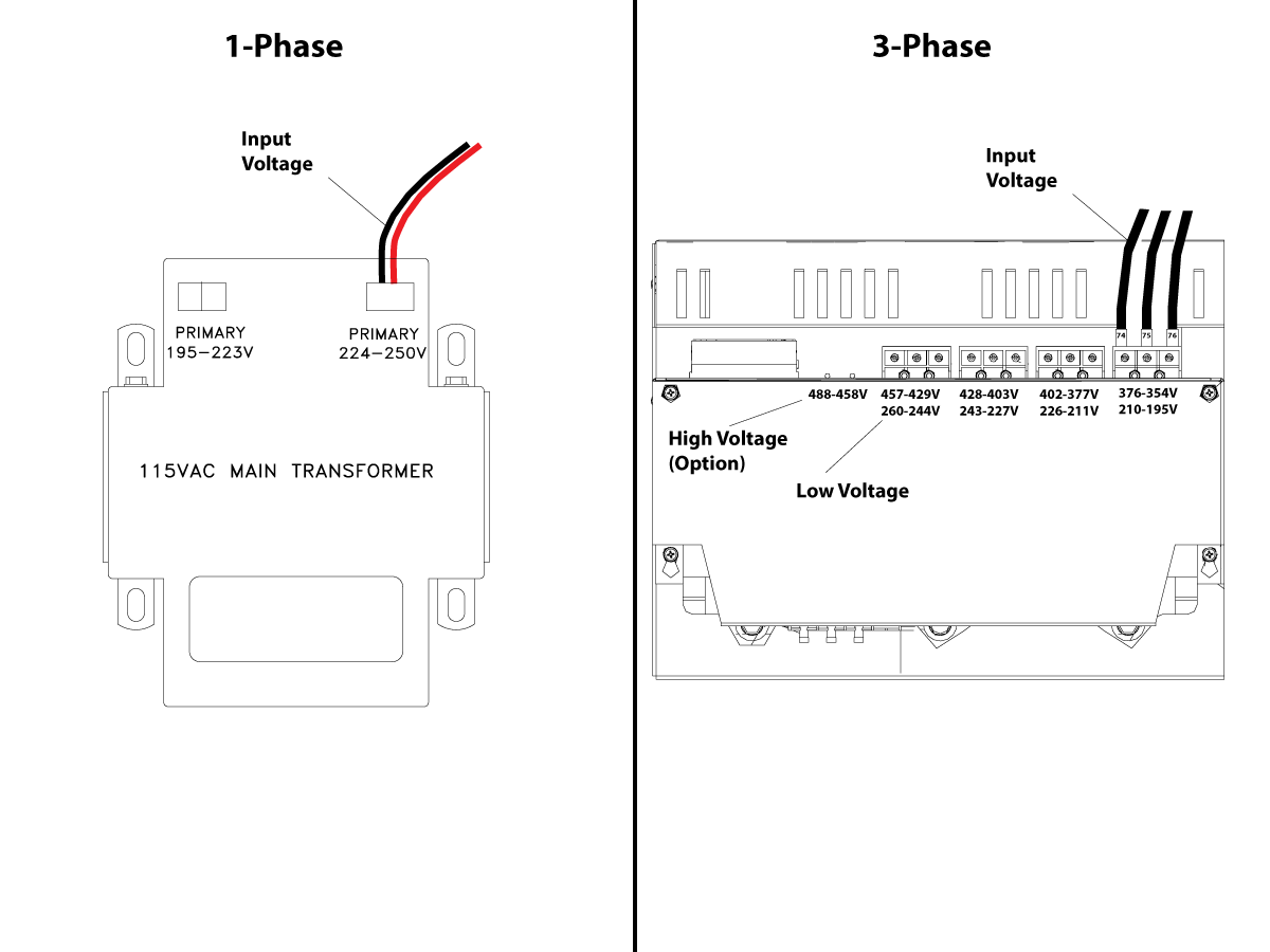
1-Phase Machines: The input voltage cable must be moved to the connector which corresponds to the average voltage measured in the above step.

3-Phase Machines:  The input voltage cables labeled 74, 75, and 76 must be moved to the terminal block triple which corresponds to the average voltage measured in the above step.

5

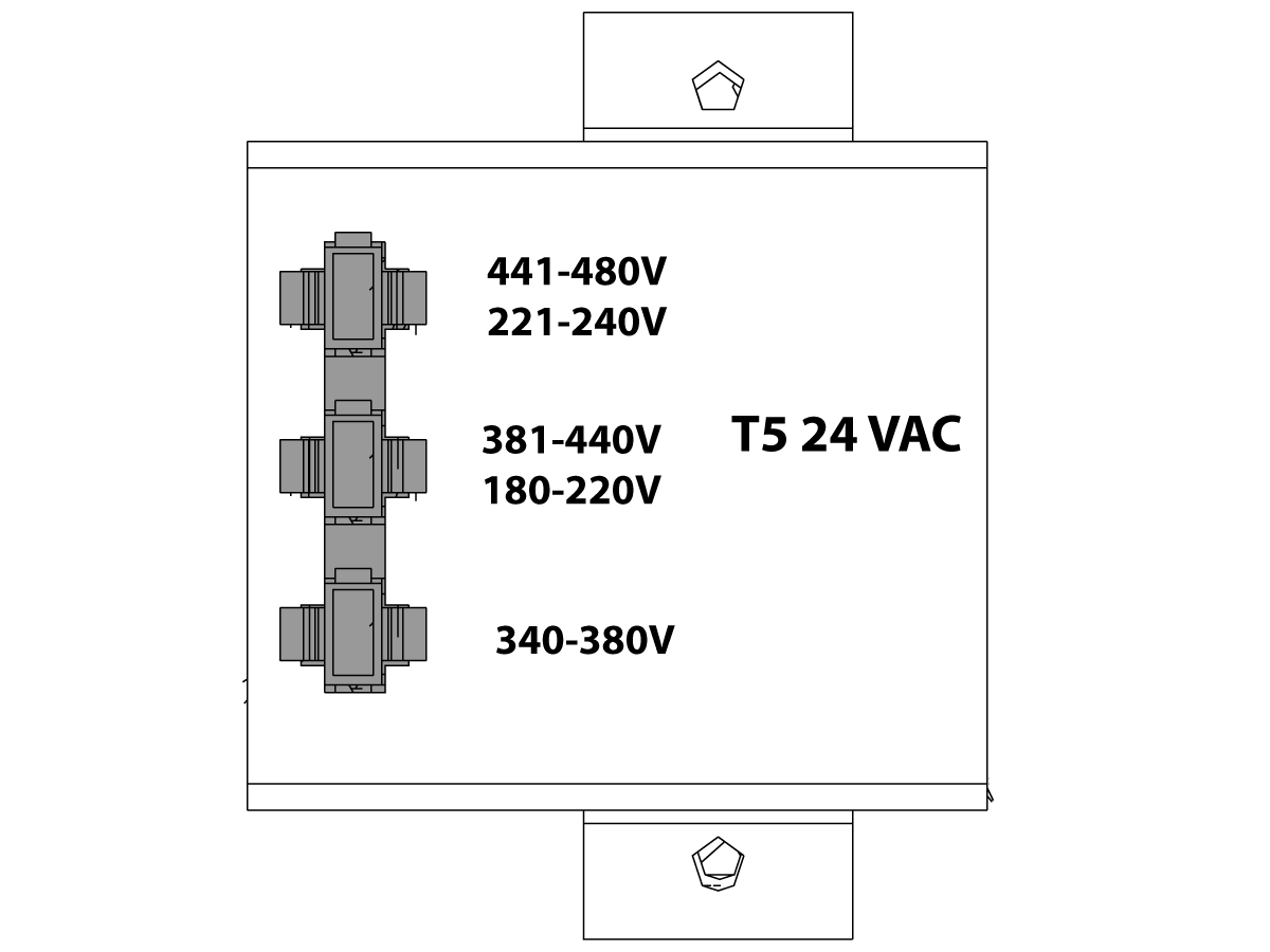
Transformer T5 supplies 24VAC used to power the main contactor. There are two versions of this transformer for use on a 240 and 400V machines. The 240V transformer has two input connectors located about two inches from the transformer, which allow it to be connected to either 180-220V or 221-240V.

Users that have 220V-240V RMS input power should use the connector labeled 221-240V, while users with 190-220V input power should use the connector labeled 180-220V. Failure to use the correct input connector will result in either overheating of the main contactor or failure to reliably engage the main contactor.

The 480V (option) T5 transformer has three input connectors, labeled 340-380V, 381-440V and 441-480V.

Users with 340-380V 50/60Hz power should use the 340-380V connector while users with 380V-440V 50/60Hz power should use the 381-440V connector.

Important: Set the main circuit breaker to ON. Check for evidence of problems, such as the smell of overheating components or smoke. If such problems are indicated, immediately set the main circuit breaker to OFF and call the factory before proceeding.

After the power is on, measure the voltage across the bottom terminals on the main circuit breaker. It should be the same as the measurements where the input power connects to the main breaker. If there are any problems, check the wiring.

6

Apply power to the control by pressing the Power-On switch on the front panel.

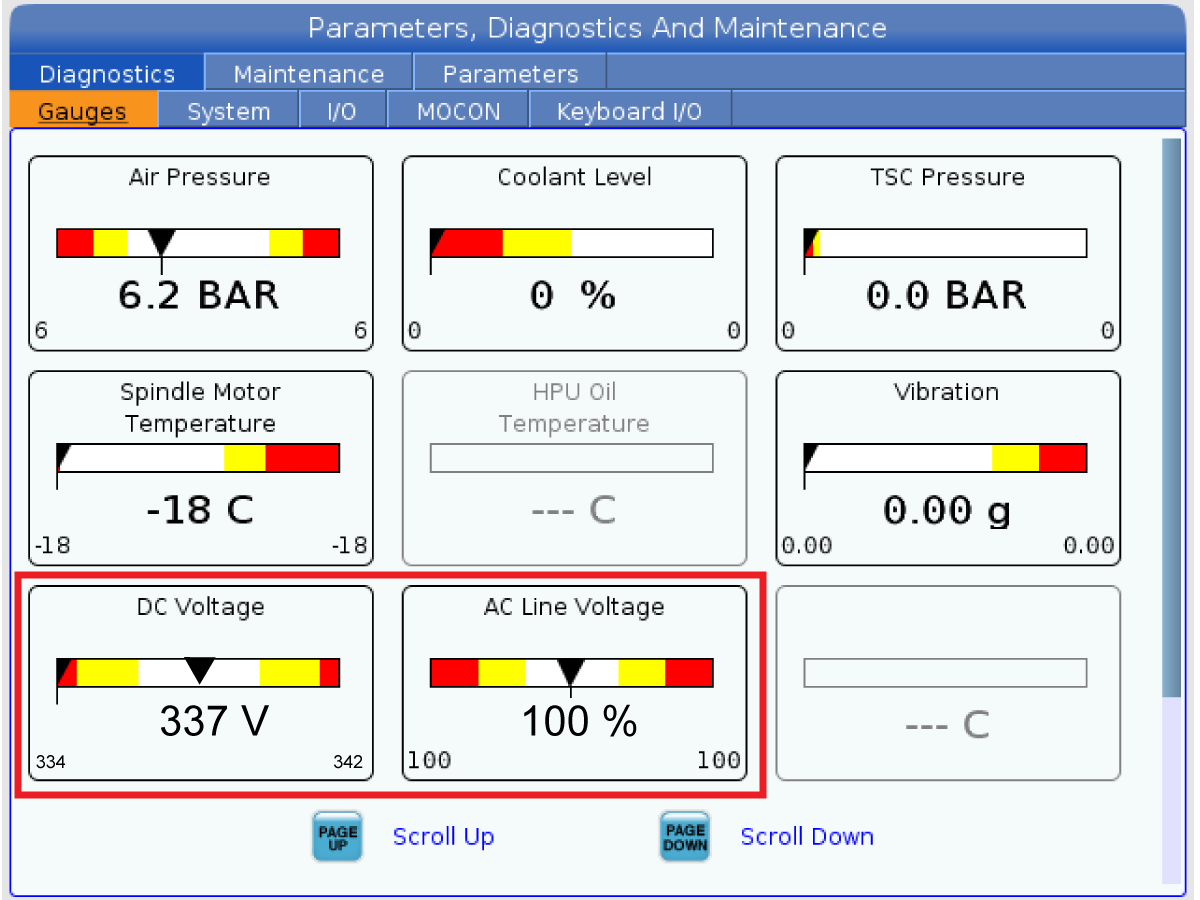
Check the DC Voltage and AC Line Voltage gauges in Diagnostics. The DC Voltage gauge must read between 310 - 360V. The AC Line Voltage must be between 90 and 105 percent. If the voltage is outside these limits, turn off the power and recheck steps 2 and 3. If the voltage is still outside these limits, call the factory.

7

Electrical power must be phased properly to avoid damage to your equipment. The Power Supply Assembly PC board incorporates a "Phase Detect" circuit with neon indicators. When the orange neon is lit (NE5), the phasing is incorrect. If the green neon is lit (NE6), the phasing is correct. If both neon indicators are lit, you have a loose wire; check the connections. Adjust phasing by setting the source power to off and then swapping L1 and L2 of the incoming power lines at the main circuit breaker.

Danger: ALL POWER TO CNC MUST BE TURNED OFF LOCKOUT-TAGOUT AT THE SOURCE PRIOR TO ADJUSTING PHASING. ALWAYS DOUBLE CHECK THE INCOMING LINES WITH AN AC VOLTAGE DETECTOR.

Turn off the power and set the main circuit breaker to OFF. Close the door, lock the latches, and turn the power back on.

Remove the key from the control cabinet and give it to the shop manager.

8

Activation

When the machine is properly placed and connected to both air and electrical power, it is ready for final installation (removing shipping blocks, leveling, spindle sweep, etc.) and software activation. The HFO service technician does this. Contact the local HFO to schedule the work.

IMPORTANT:  Machines equipped with motion sensors must be rough‑leveled before attempting to arm the motion sensor.  For detailed instructions, refer to Service Notification - SA0007.  Access to this document is restricted to Haas Factory Outlet personnel.

Odstranjevanje oklepajev

Updated

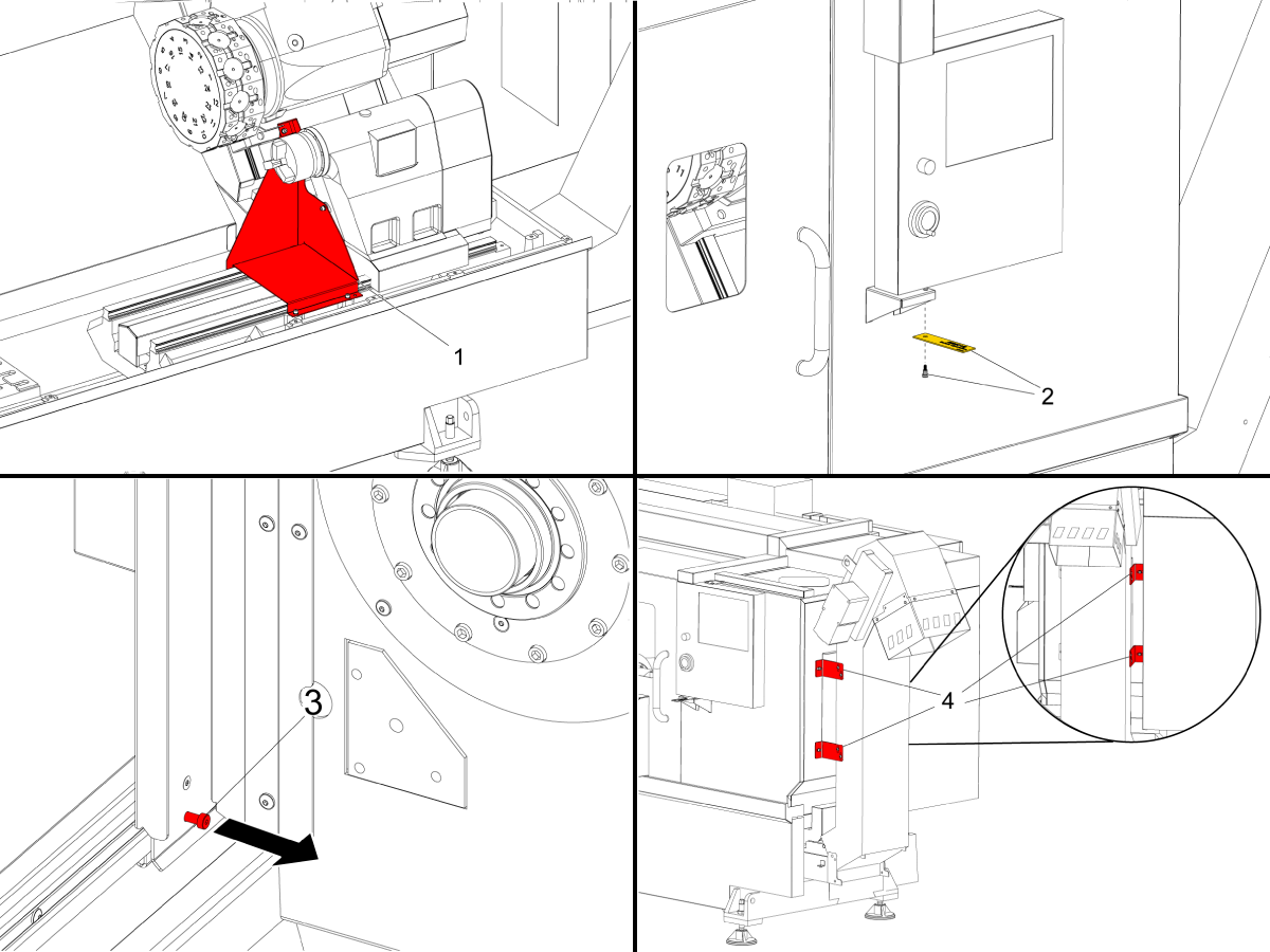
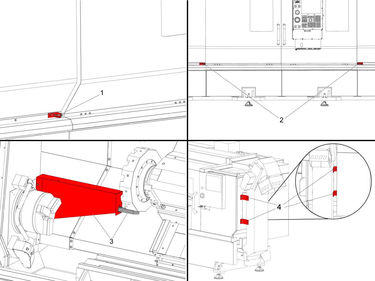
Za stroje serije ST-10-35 in stružnice DS-30Y

Odstranite odprtino za nosilni nosilec [1].

Odstranite ramenski vijak na nadzorni plošči [2]. Stroji z omarico za obešalo imajo nosilec za transport na desni strani krmilnika. 

Odstranite ramenski vijak na nadzorni plošči [3].

Odstranite nosilne nosilce transporterja odrezkov [4]. Privijte navojne luknje v ploščatem jeklu z vijaki nosilca za transport.

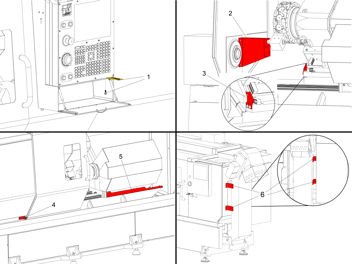
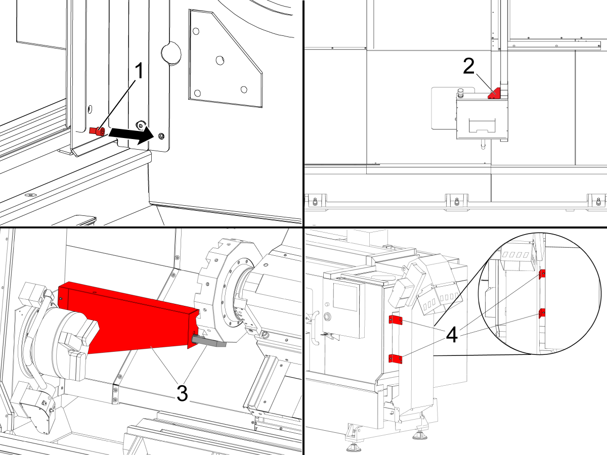
Za stružnice ST-30/35/DS-30Y pred ponovnim zagonom

Odstranite ramenski vijak na nadzorni plošči [1]. 

Odstranite nosilni nosilec za vreteno [2].

Odstranite nosilni nosilec osi Y [3].

Odstranite nosilec za vrata [4].

Odstranite drugi nosilec za vreteno [5]. Glejte Odstranjevanje nosilca DS za pošiljanje AD0065.

Odstranite transportni trak nosilni nosilci [6].

Za stružnice ST-40/40L/45/45L/50/55 pred ponovnim zagonom

Odstranite nosilce vrat. Za ST-40/45 obstaja en nosilec. Za ST-40L / 45L / 50/55 obstajata dva nosilca [1,2].

Odstranite nosilni nosilec vretena [3].

Odstranite transportni trak nosilni nosilci [4].

Namestite obešalo na stroj.

Za navodila o namestitvi obeska glejte:

ST-40/45/50/55 - obesek - namestitev

Za stroje serije ST-40-55 za ponovni zagon in stroje DS-40Y:

Odstranite ramenski vijak na nadzorni plošči [1].

Odstranite transportni nosilec za konzolo krmilnika [2].

Odstranite nosilni nosilec vretena [3].

Odstranite transportni trak nosilni nosilci [4].

OPOMBA: Za identifikacijo ST-stružnic pred ponovnim zagonom strojev glejte različico stroj serije ST - Identifikacija.

Updated

Za stroje DS-40Y:

Odstranite drugi nosilec za vreteno[1].

ST-10 / 10Y / 15 / 15Y izravnava

1

Ničelno vrnite vsako os eno za drugo ali pritisnite [POWER UP]. Pojdite skozi postopek izravnave.
Ponovite te korake, da dosežete pravilno raven stroja.

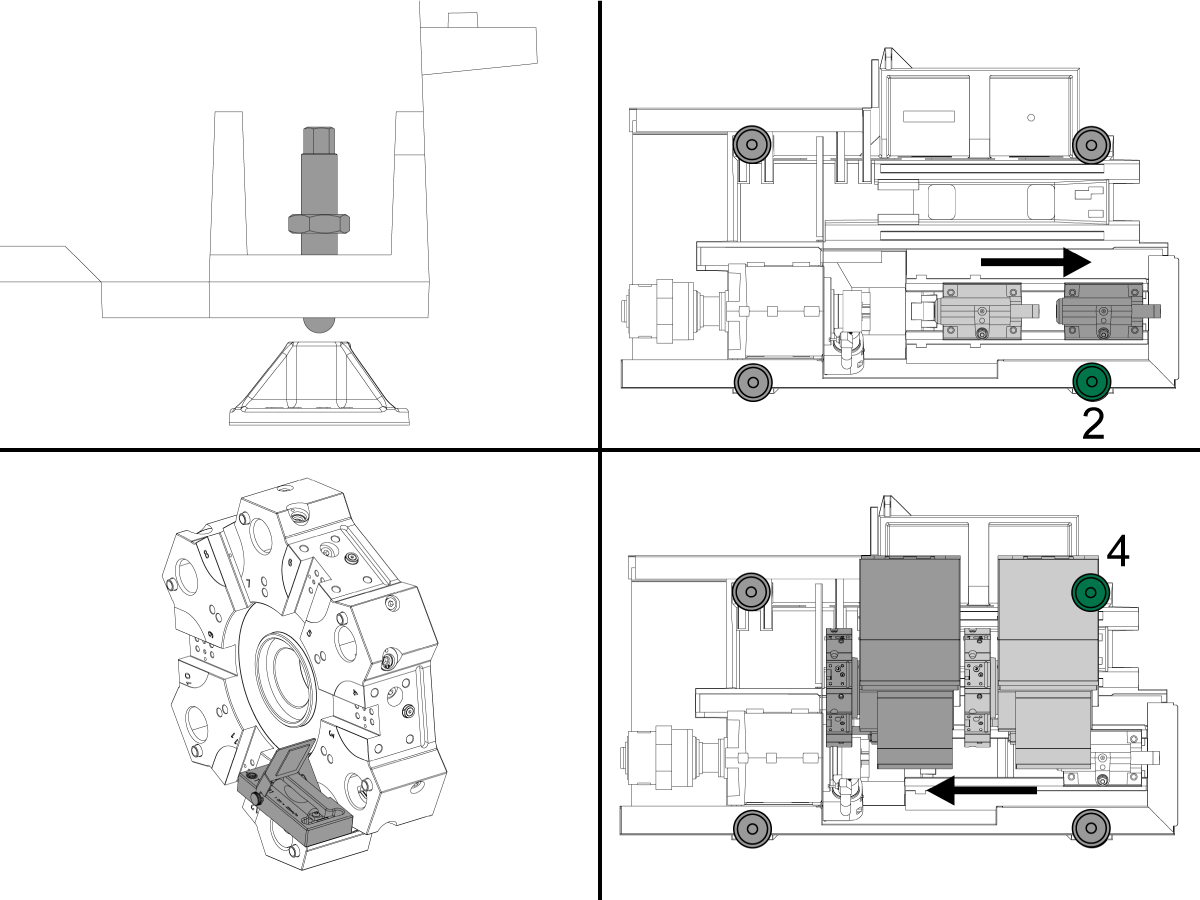
2

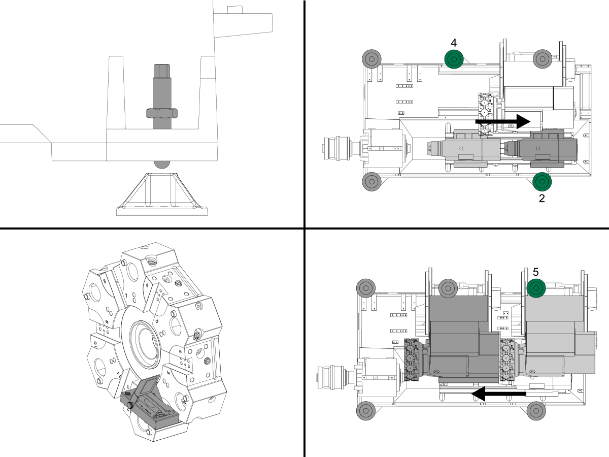
S štirimi vijaki za izravnavanje vogalov nastavite višino stroja na 3,0" nad tlemi. Zavrtite vsak vijak, tako da imata enako napetost.

Dvignite vijak 2, tako da je s podloge.

Premaknite konjiček ali drugo vreteno v referenčno pozicijo.

Orodje T-2181A namestite na odprtino tako, da je vzporedno s tlemi.

Priključite gred v sredino osi X, nato pa potisni stolp usmerite vreteno na osi Z, kolikor je to mogoče.

Poglejte manjšo raven, ki je vzporedna z osjo Z in dvignite ali spustite vijak 4, da centrirate mehurček.

3

Zdaj si oglejte večjo raven, ki je vzporedna s stranico kupole in dvignite ali spustite vijak 1, da centrirate mehurček.

Za preverjanje zasuka v stroju pomaknite vrv vzdolž osi Z nazaj v osnovni položaj.

Z večjim nivojem dvignite ali spustite vijak 2, da centrirate mehurček in počakate 10 sekund, da se mehurček naseli.

Potegnite odprtino nazaj proti vretenu in dvignite ali spustite vijak 1, da centrirate mehurček. Nadaljujte s premikanjem kupole iz domačega položaja v vreteno in prilagajajte vijaka 1 in 2, dokler se zasuk ne odstrani. 

Zategnite zaporne matice, pri čemer pazite, da vijakov ne dvignete ali spustite.

Preverite, da je stroj raven, tako da premikate odprtino vzdolž osi Z in preverite, ali je zasuk nastavljen, in nastavite do nastavitve.

ST-20 / 20Y / 25 / 25Y izravnava

1

Ničelno vrnite vsako os eno za drugo ali pritisnite[POWER UP]. Pojdite skozi postopek izravnave. Ponovite te korake, da dosežete pravilno raven stroja.

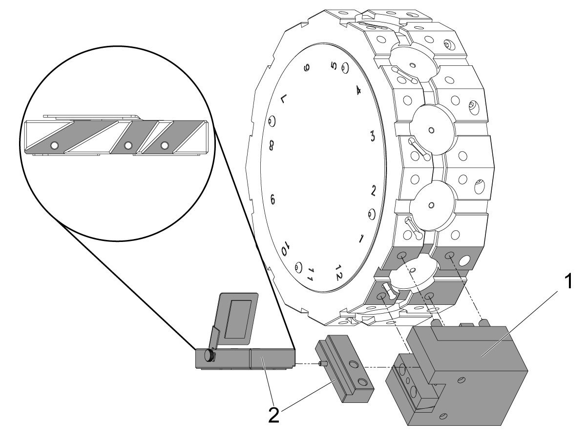
Opomba: Če ima vaš stroj kupolo BMT, v žep 1 namestite držalo orodja BMT65OD-1 [1]. Sestavite T-2181A [2], tako da je raven vzporedna s tlemi. Obstajajo tri reže, odvisno od kota klina stroja. Z držalom orodja pritrdite nivo ali s pomočjo vijakov pritrdite raven v držalo orodja.

2

S štirimi vijaki za izravnavanje vogalov nastavite višino stroja na 3,0" nad tlemi. Zavrtite vsak vijak, tako da imata enako napetost.

Dvignite vijaka 2 in 4, tako da sta odklenjena.

Premaknite konjiček ali drugo vreteno v referenčno pozicijo.

Orodje T-2181A namestite na odprtino tako, da je vzporedno s tlemi.

Tirna vrvica v sredino osi X nato potisni stolp proti vretenu na osi Z, kolikor je to mogoče.

Poglejte manjšo raven, ki je vzporedna z osjo Z in dvignite ali spustite vijak 5, da centrirate mehurček.

3

Zdaj si oglejte večjo raven, ki je vzporedna s stranico kupole in dvignite ali spustite vijak 1, da centrirate mehurček.

Za preverjanje zasuka v stroju pomaknite vrv vzdolž osi Z nazaj v osnovni položaj.

Z večjim nivojem dvignite ali spustite vijak 2, da centrirate mehurček in počakate 10 sekund, da se mehurček naseli..

Potegnite odprtino nazaj proti vretenu in dvignite ali spustite vijak 1, da centrirate mehurček. Nadaljujte s premikanjem odprtine od domačega položaja do vretena in nastavite vijaka 1 in 2, dokler se zasuk ne odstrani.

Ročno spustite vijak 4 na blazinico in uporabite ključ in privijte samo za 10 °.

Ne zategujte več, ker boste spremenili nivo stroja.

Zategnite zaporne matice, pri čemer pazite, da vijakov ne dvignete ali spustite.

Preverite, da je stroj raven, tako da premikate odprtino vzdolž osi Z in preverite, ali je zasuk nastavljen, in nastavite do nastavitve.

ST-30 / 30Y / 35 / 35Y / 40Y in DS-30Y/40Y izravnava

1

Ničelno vrnite vsako os eno za drugo ali pritisnite [POWER UP]. Pojdite skozi postopek izravnave. Ponovite te korake, da dosežete pravilno raven stroja.

 Opomba: Če ima vaš stroj BMT revolversko glavo, namestite Držalo orodja BMT OD-1 [1] do žepa 1. Sestavite T-2181A [2], tako da je raven vzporedna s tlemi. Obstajajo tri reže, odvisno od kota klina stroja. Z držalom orodja pritrdite nivo ali s pomočjo vijakov pritrdite raven v držalo orodja.

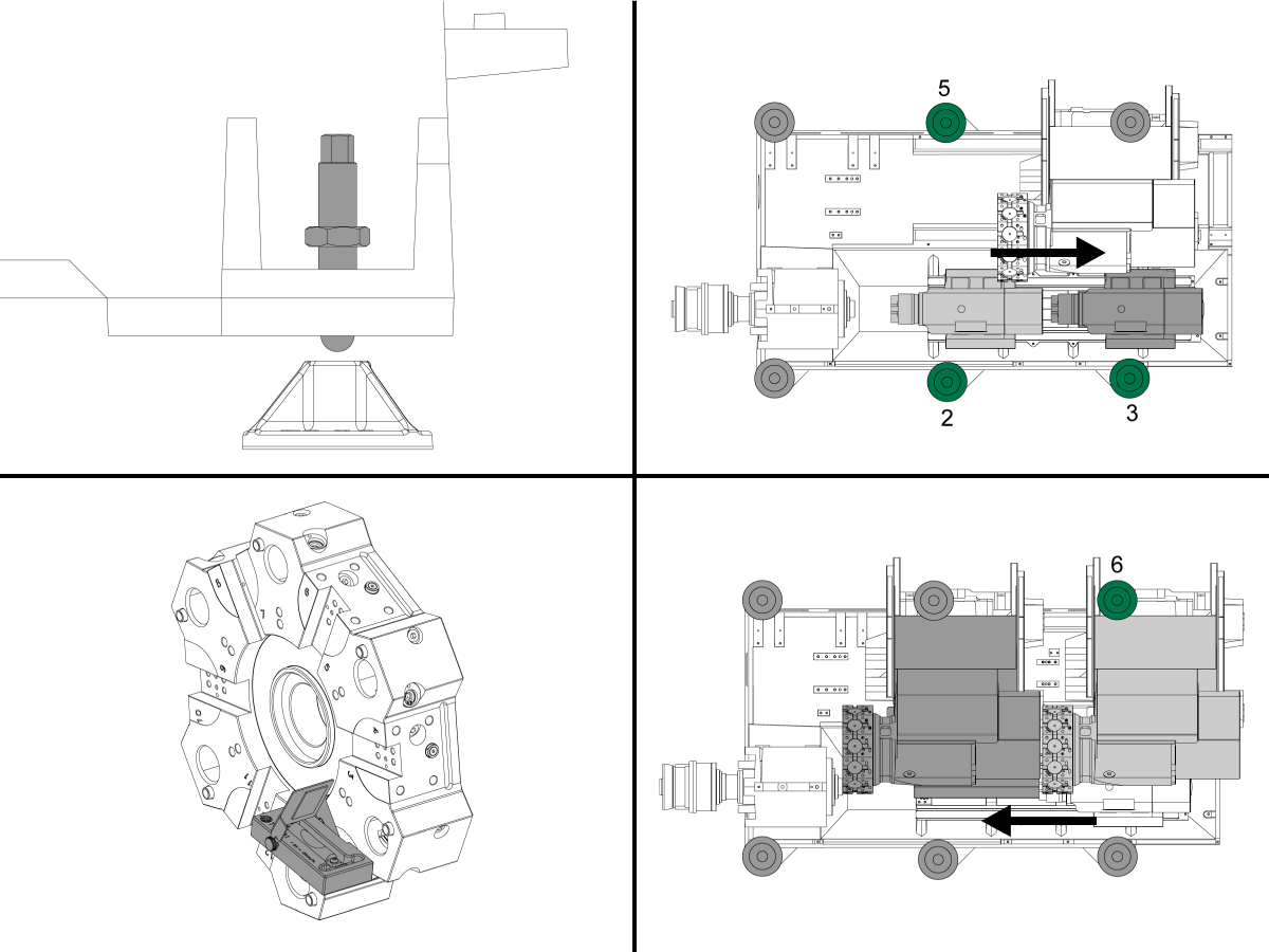
2

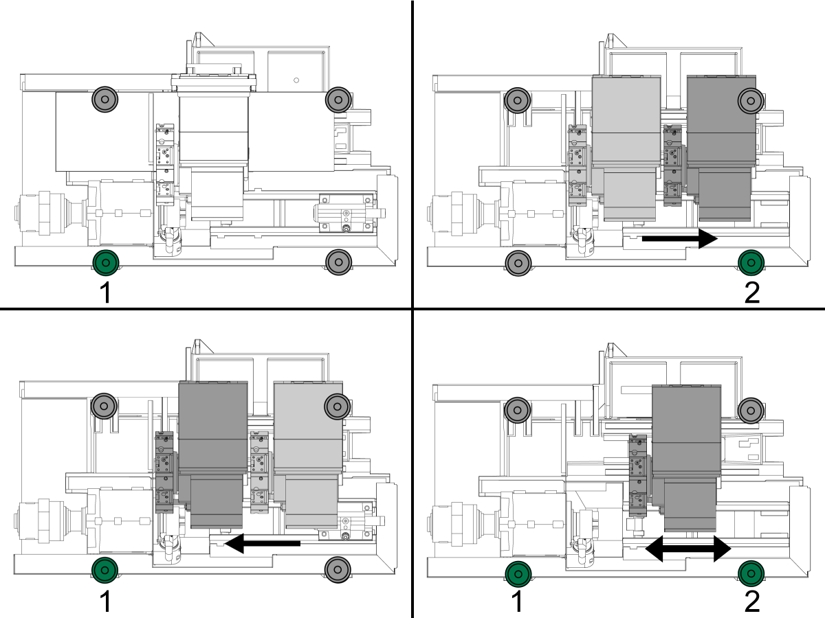
S štirimi vijaki za izravnavanje vogalov nastavite višino stroja na 3,0" nad tlemi. Zavrtite vsak vijak, tako da imata enako napetost.

Dvignite vijake 2, 3 in 5, tako da so odklonjeni z blazinic.

Premaknite konjiček ali drugo vreteno v referenčno pozicijo

Orodje T-2181A namestite na odprtino tako, da je vzporedno s tlemi.

Tirna vrvica v sredino osi X nato potisni stolp proti vretenu na osi Z, kolikor je to mogoče.

Poglejte manjšo raven, ki je vzporedna z osjo Z in dvignite ali spustite vijak 6, da centrirate mehurček.

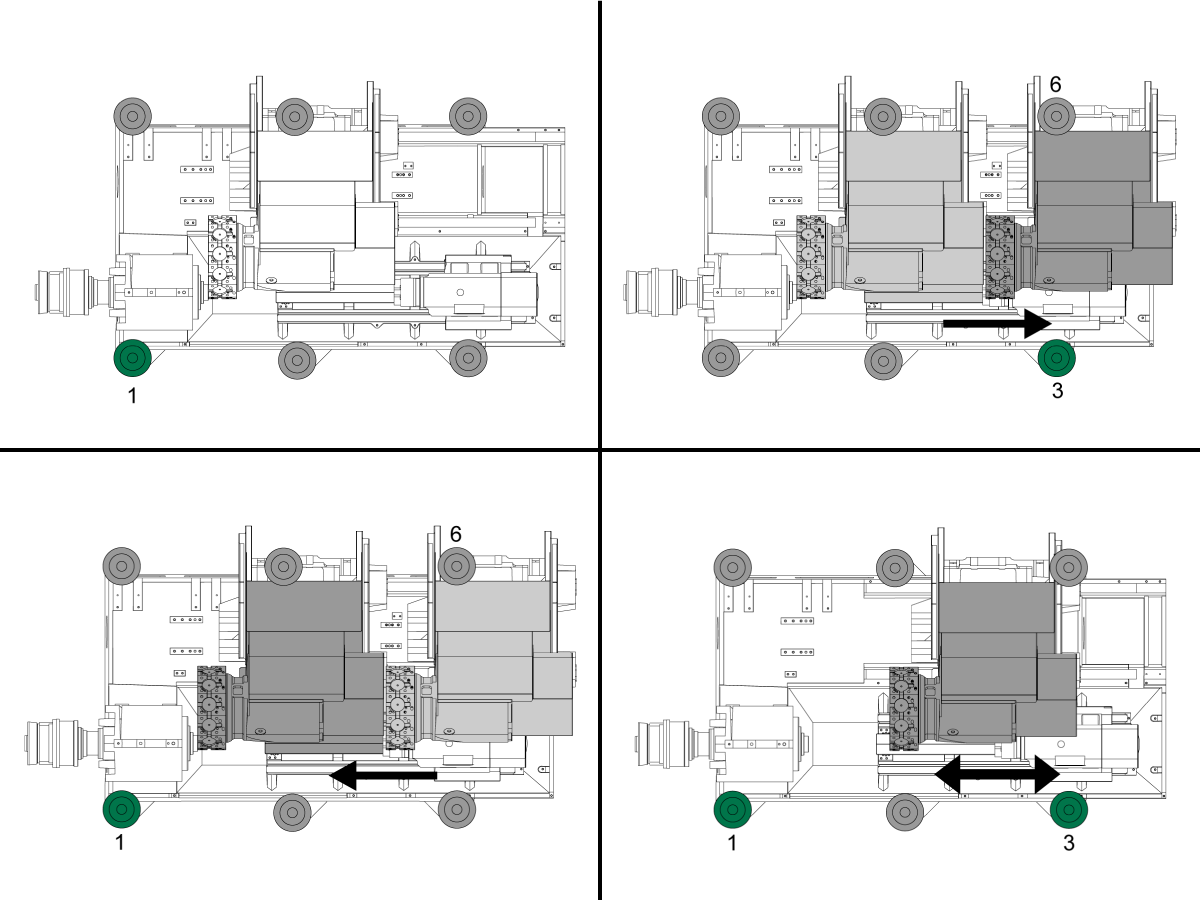
3

Zdaj si oglejte večjo raven, ki je vzporedna s stranico kupole in dvignite ali spustite vijak 1, da centrirate mehurček.

Za preverjanje zasuka v stroju pomaknite vrv vzdolž osi Z nazaj v osnovni položaj.

Z večjim nivojem dvignite ali spustite vijak 3, da centrirate mehurček in počakate 10 sekund, da se mehurček naseli..

Potegnite odprtino nazaj proti vretenu in dvignite ali spustite vijak 1, da centrirate mehurček. Nadaljujte s premikanjem odprtine od domačega položaja do vretena in nastavite vijaka 1 in 3, dokler se zasuk ne odstrani.

Ročno spustite vijaka 2 in 5 na blazinice in uporabite ključ in privijte le za 10 °.

Ne zategujte več, ker boste spremenili nivo stroja.

Zategnite zaporne matice, pri čemer pazite, da vijakov ne dvignete ali spustite.

Preverite, da je stroj raven, tako da premikate odprtino vzdolž osi Z in preverite, ali je zasuk nastavljen, in nastavite do nastavitve.

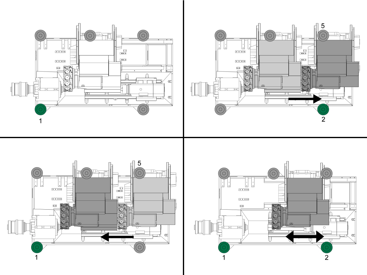
ST-40 / 40L / 45 / 45L / 50/55 Izravnava

1

Ničelno vrnite vsako os eno za drugo ali pritisnite [POWER UP]. Pojdite skozi postopek izravnave.
Ponovite te korake, da dosežete pravilno raven stroja.

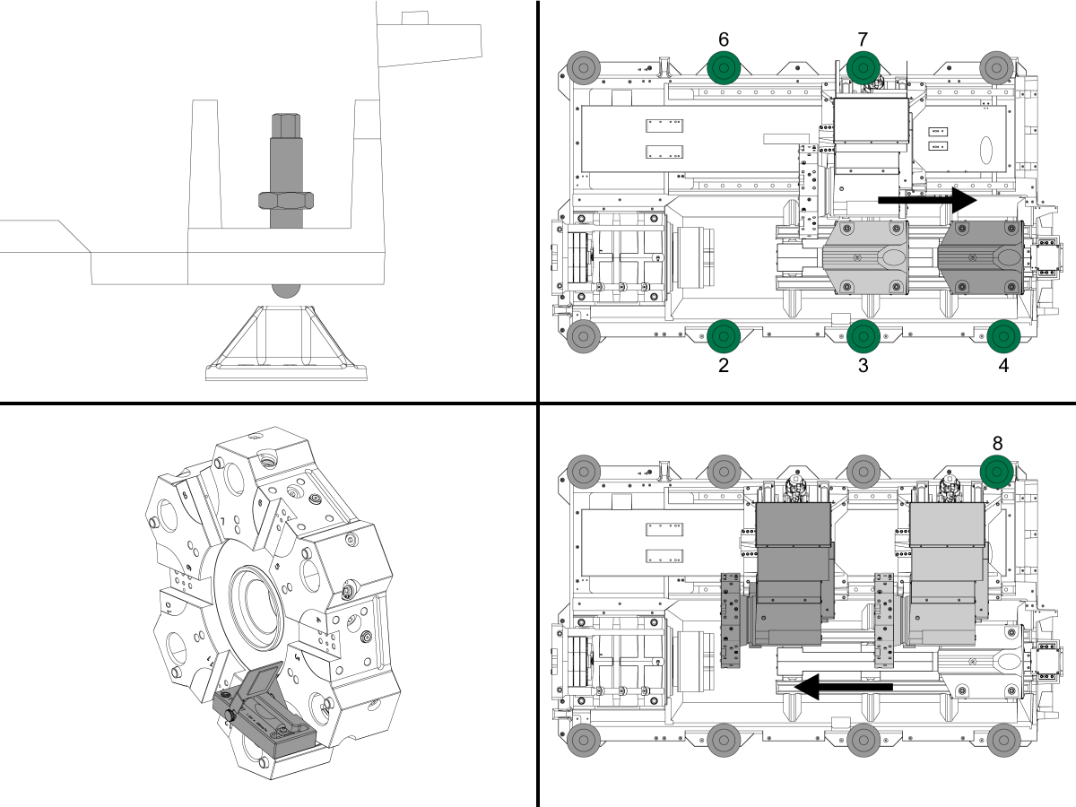
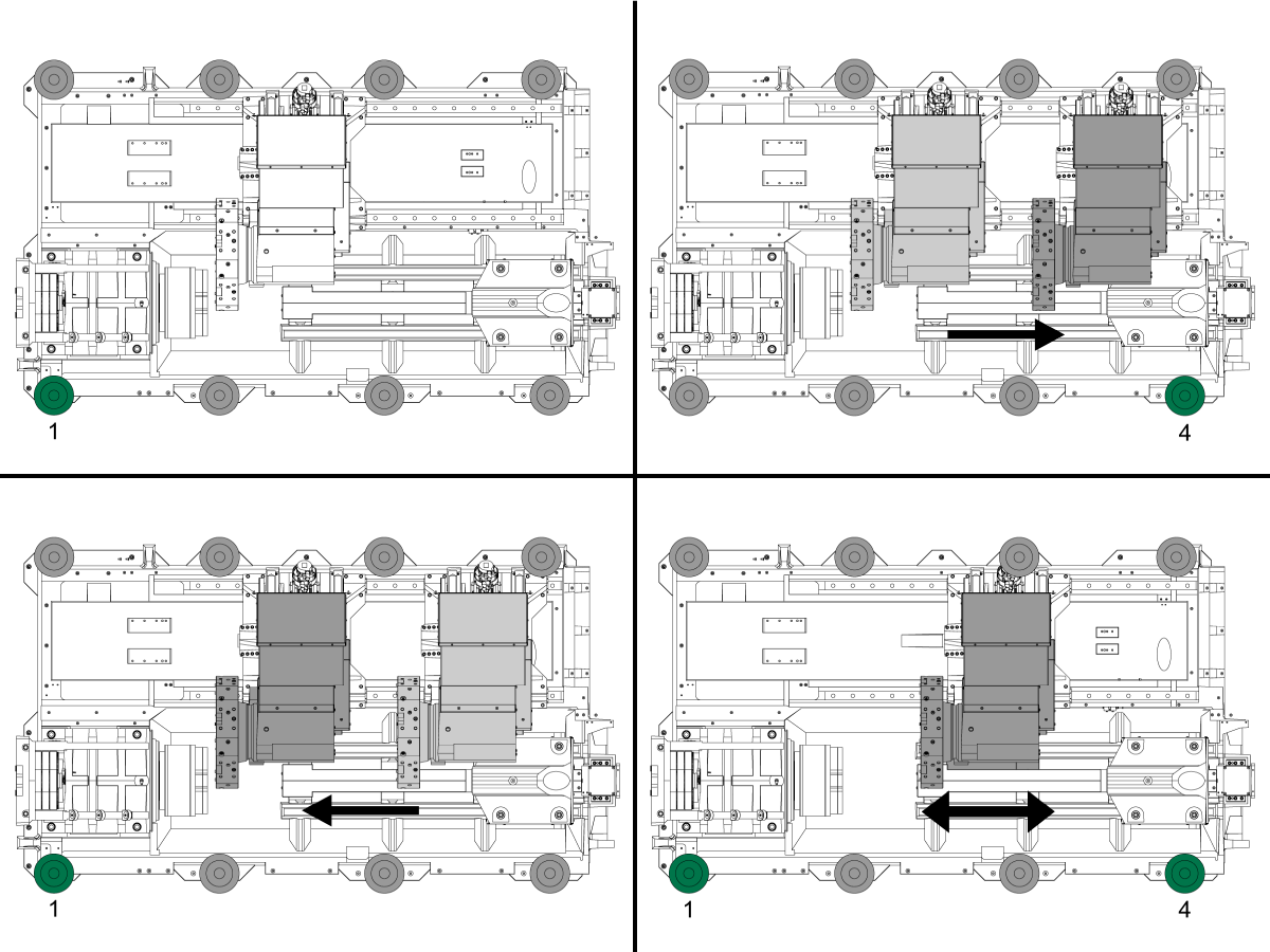
2

S štirimi vijaki za izravnavanje vogalov nastavite višino stroja na 3,0" nad tlemi. Zavrtite vsak vijak, tako da imata enako napetost.

Dvignite vijake 2, 3, 4, 6 in 7, tako da so izven blazinic.

Premaknite konjiček ali drugo vreteno v referenčno pozicijo

Orodje T-2181A namestite na odprtino tako, da je vzporedno s tlemi.

Tirna vrvica v sredino osi X nato potisni stolp proti vretenu na osi Z, kolikor je to mogoče.

Poglejte manjšo raven, ki je vzporedna z osjo Z in dvignite ali spustite vijak 8, da centrirate mehurček.

3

Zdaj si oglejte večjo raven, ki je vzporedna s stranico kupole in dvignite ali spustite vijak 1, da centrirate mehurček.

Za preverjanje zasuka v stroju pomaknite vrv vzdolž osi Z nazaj v osnovni položaj.

Z večjim nivojem dvignite ali spustite vijak 4, da centrirate mehurček in počakate 10 sekund, da se mehurček naseli..

Potegnite odprtino nazaj proti vretenu in dvignite ali spustite vijak 1, da centrirate mehurček. Nadaljujte s premikanjem kupole iz domačega položaja v vreteno in prilagajanjem vijakov 1 in 4, dokler se zasuk ne odstrani.

Ročno spustite vijake 2, 3, 6 in 7 na blazinice in uporabite ključ in privijte le za 10 °.

Ne zategujte več, ker boste spremenili nivo stroja.

Zategnite zaporne matice, pri čemer pazite, da vijakov ne dvignete ali spustite.

Preverite, da je stroj raven, tako da premikate odprtino vzdolž osi Z in preverite, ali je zasuk nastavljen, in nastavite do nastavitve.

Preverjanje mazanja

1

Run the spindle run-in program.

 Note: For 10K spindles and above use a balanced tool holder

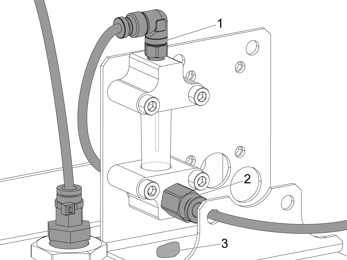
Examine the sight glass, make sure the correct number of drops are fall through the sight glass.

Examine the fittings [1,2] on top of the oil pump tank.

The oil collects on top of the oil pump tank [3] either behind or in front of the sight glass bracket, underneath the leaking fitting.

Tighten any leaking fittings.

2

Go to the Maintenance tab.

Press [F2] to cycle an axis lubrication test.

Inspect the gauge on the lubrication system.  Make sure it holds pressure.

Delovanje stroja

1

Updated

Preizkusite delovanje emulzije - Večstopenjska črpalka emulzije

Če je vaš stroj opremljen s črpalko emulzije z več stopnjami, izvedite naslednje delovanje:

  • Prepričajte se, da so priključki cevi na črpalki emulzije z več stopnjami priključeni in pritrjeni. 
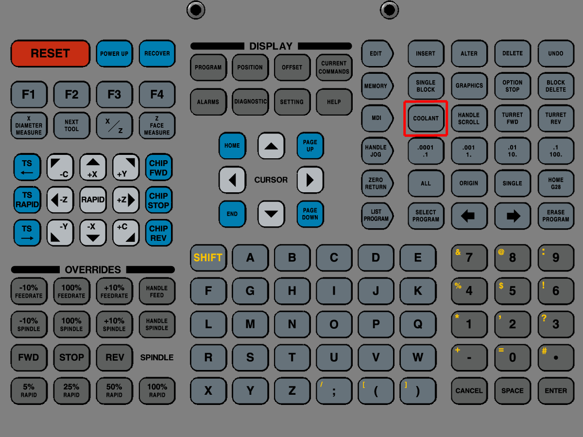
  • Zaženite emulzijo s pritiskom  [COOLANT] na konzoli krmilnika.
  • Preverite puščanje okoli priključkov črpalke emulzije in cevi.

2

Updated

Preizkusite delovanje visokotlačnega hladilnega sredstva (HPC)

Če je vaš stroj opremljen s sistemom visokotlačne emulzije, izvedite naslednje delovanje:

  • V [MDI] izdajte ukaz: M88; G04 P10.; M89;
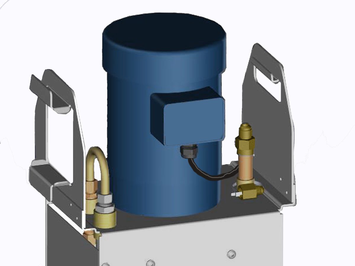
  • Preverite, ali se motor črpalke HPC vklopi.
  • Preverite tesnjenje na priključku razdelilnika hladilne tekočine in cevi.

3

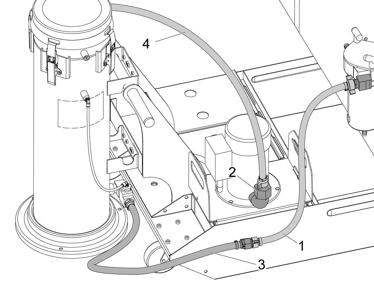
Namestitev pomožnega filtra hladilne tekočine

  • Če vaš stroj vključuje možnost Pomožni filter hladilne tekočine, izvedite postopek namestitve

Za navodila o tem, kako izvajati Postopek namestitve pomožnega filtra hladilne tekočine glejte:

Namestitev pomožnega filtra hladilne tekočine
Chips and Coolant- coolant refill. Product of Haas CNC machine tools.

4

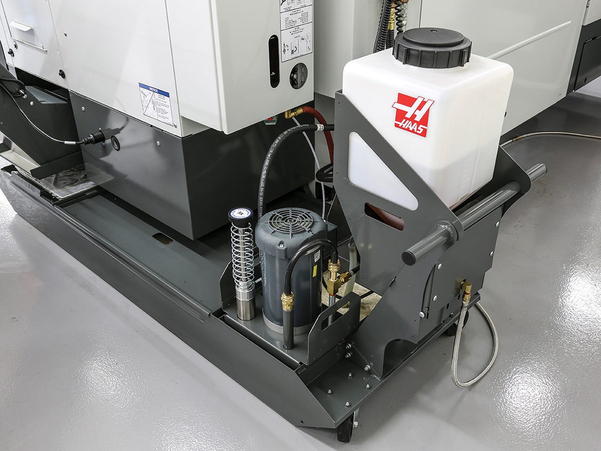
Kalibracija napolnite hladilno tekočino 

  • Če vaša naprava vključuje možnost Dolivanje hladilne tekočine, izvedite postopek umerjanja.

Za navodila o namestitvi in izvedbi postopka umerjanja hladilne tekočine ponovno glejte:

Kalibracija ponovnega polnjenja emulzije

5

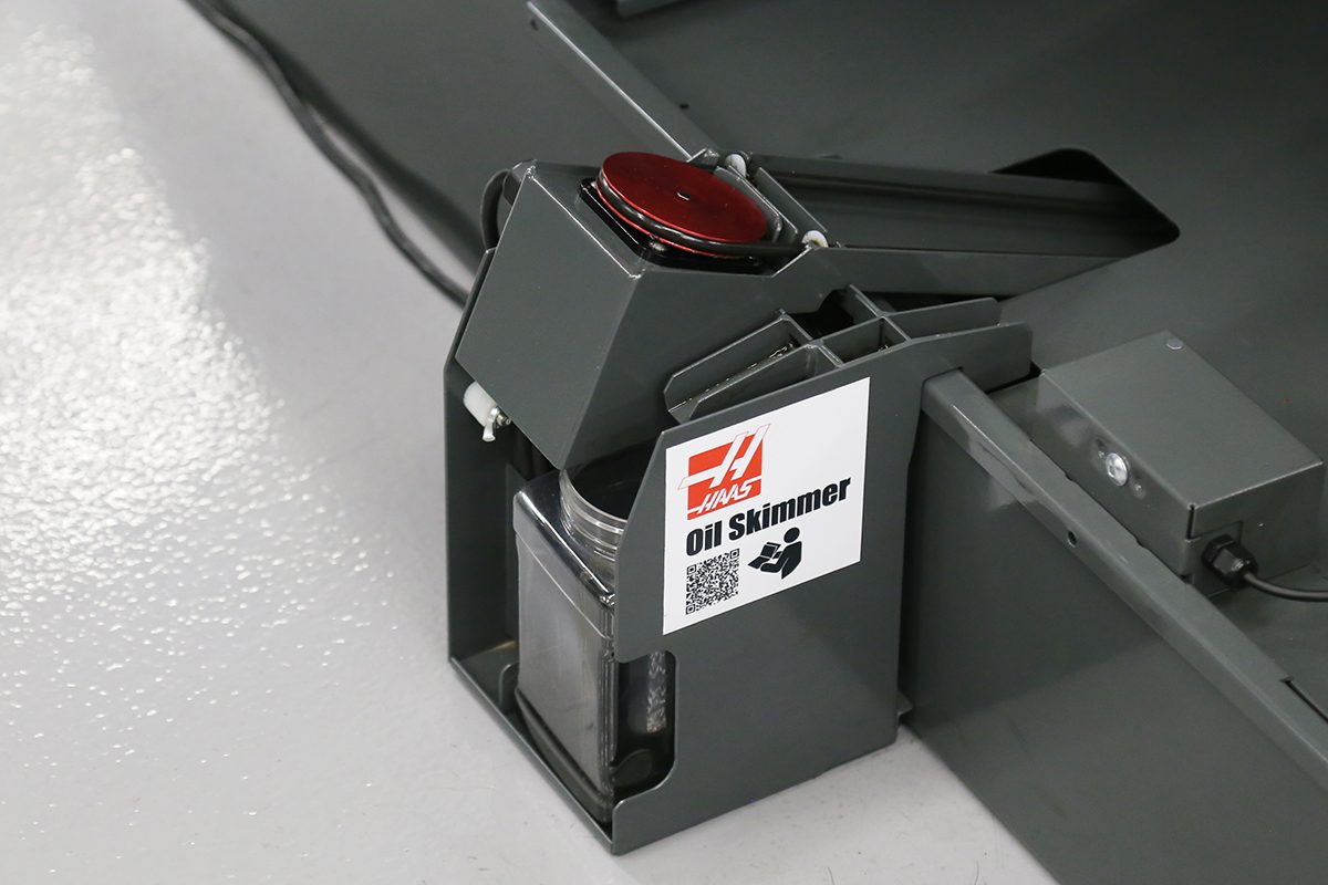
Namestitev kurilnega olja

  • Če vaša naprava vključuje možnost Oil Skimmer, izvedite postopek namestitve

Za navodila o izvedbi postopka namestitve Oil Skimmer glejte:

Namestitev kurilnega olja

6

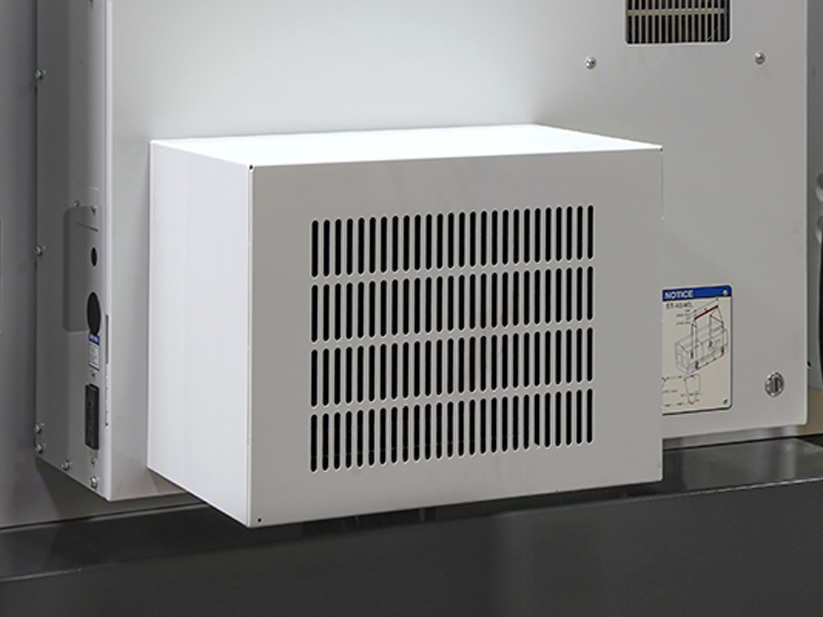
Namestitev hladilnika kabineta

  • Če vaša naprava vključuje možnost Cabinet Cooler, izvedite postopek namestitve

Za navodila o tem, kako izvajati Postopek namestitve hladilnika kabineta glejte:

Namestitev hladilnika kabineta
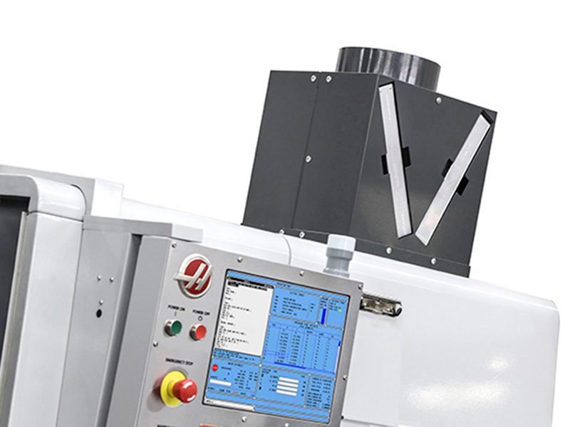
Chips and Coolant Excel Exhaust. Product of Haas CNC machine tools.

7

Namestitev izpušnega prostora v ohišju

  • Če vaša naprava vključuje opcijo Izpušni prostor, izvedite postopek namestitve

Za navodila o tem, kako izvajati Priloga Proces namestitve izpušnih plinov glejte:

Namestitev izpušnega prostora v ohišju

8

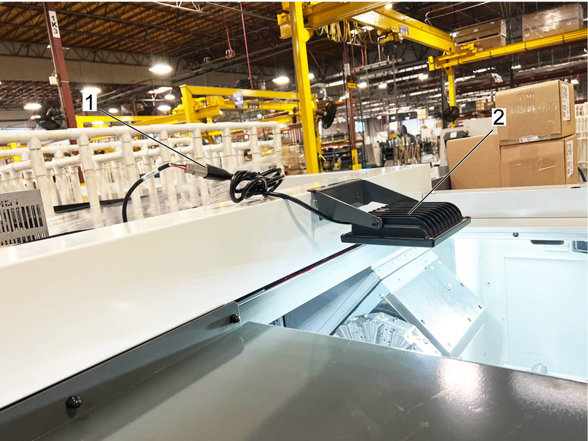
Namestitev 24V magnetne delovne luči

Za navodila o tem, kako izvesti postopek namestitve magnetne delovne luči, si oglejte:

Namestitev 24V magnetne delovne luči za stružnico

9

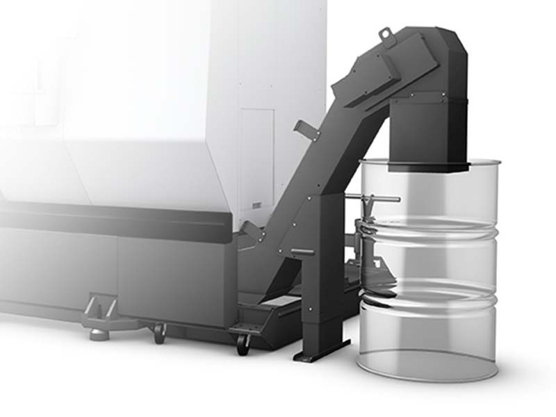
Namestitev transportnega čipa

  • Če vaša naprava vključuje možnost Chip Conveyor, izvedite postopek namestitve

Za navodila o izvedbi postopka namestitve Chip Conveyor glejte:

Namestitev transportnega čipa

10

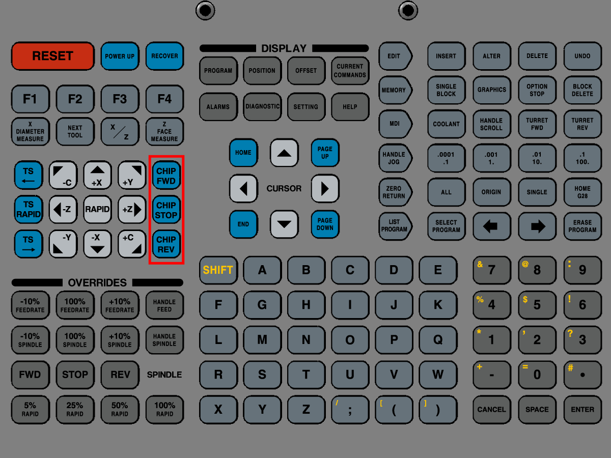
Preizkusni transportni čipi

  • Preizkusite transporter čipov s pritiskom na [CHIP FWD],  [CHIP STOP], in [CHIP REV] gumbi na obesku za upravljanje

11

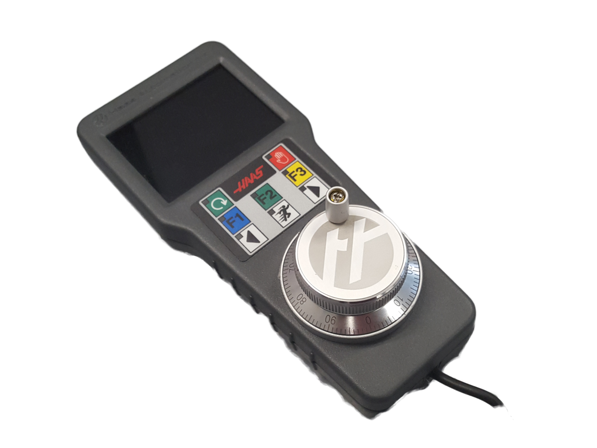
Namestitev daljinskega ročaja Jog Color

  • Če vaša naprava vključuje možnost Remote Jog Handle Color, izvedite postopek namestitve

Za navodila o tem, kako izvajati Postopek namestitve oddaljene ročice Jog Color (glejte:

Namestitev RJH-C

12

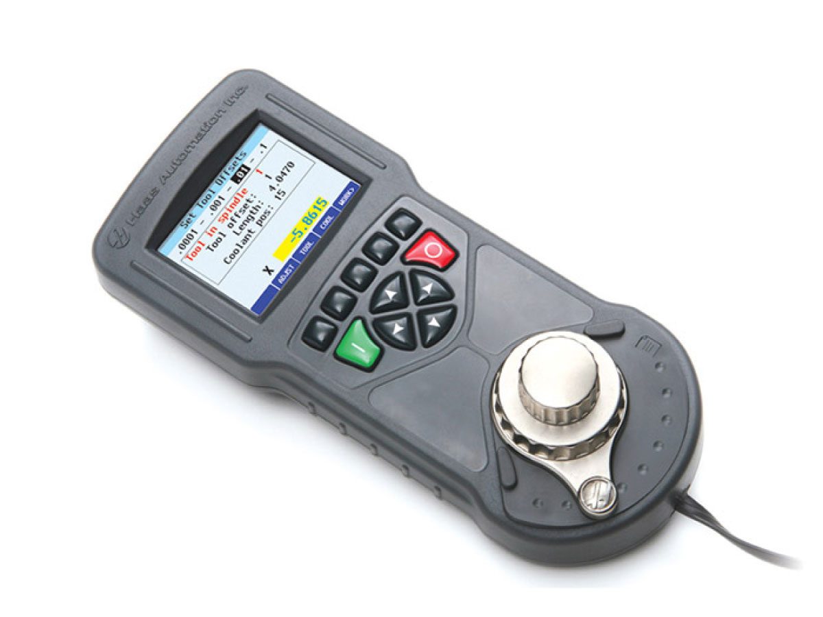
Namestitev daljinskega ročaja Jog Touch

  • Če vaša naprava vključuje možnost Remote Jog Handle Touch, izvedite postopek namestitve

Za navodila o tem, kako izvajati Postopek namestitve na daljavo Jog Handle Touch glejte:

Namestitev RJH-T

13

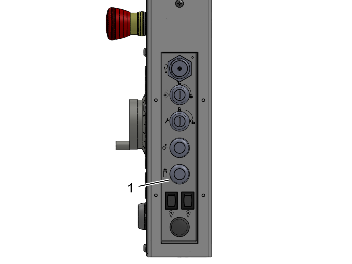
Preizkusite zapore vrat

  • Pojdi na MDI. Vtipkajte S500 M3; Pritisnite [ENTER]. Prepričajte se, da naprava ni v načinu nastavitve. Preverite ključno stikalo na strani obeska.
  • Z odprtimi vrati pritisnite [CYCLE START]. Stroj bi moral ukazati, da se vrata zaprejo in pritisk[CYCLE START].
  • Z zaprtimi vrati pritisnite [CYCLE START]. Zaporni zatič se iztegne in vreteno se začne vrteti.
  • Medtem ko so ključavnice, poskusite odpreti vrata. 
  • Vreteno se ne sme nehati vrteti, ampak če se vreteno ustavi, je potrebna ponovna nastavitev. 

14

Preizkus samodejnega zračnega curka (AJB)

Odprite ventil primarnega zraka. To dovaja zrak v stroj.

Preizkusite AJB:

  • M12: Glavna vretena Air Jet Blast ON
  • M13: Ustrezno pihanje glavnega vretena Air Jet OFF
Moji stroji
  • M112: Ventilator sekundarnega zračnega curka vretena vklopljen
  • M113: Utripanje sekundarnega zračnega vretena vretena OFF

Več informacij o teh kodah najdete v spodnjem priročniku za stružnico.

Priročnik za upravljavca stružnice

15

Preizkusite možnost samodejnih vrat

  • Pokličite samodejna vrata s pomočjo gumba Samodejna vrata na strani obeska.
  • Če se naprava alarmira, ne zapre pravilno ali se močno zapre, preverite, ali je stikalo za zaklepanje vrat ročno in na monitorju pravilno vklopljeno.
  • Če pride do neusklajenosti, prilagodite varnostno stikalo vrat tako, da ga premaknete noter ali ven, da zagotovite pravilno vpenjanje ključa stikala.

16

Preizkusne varnostne značilnosti

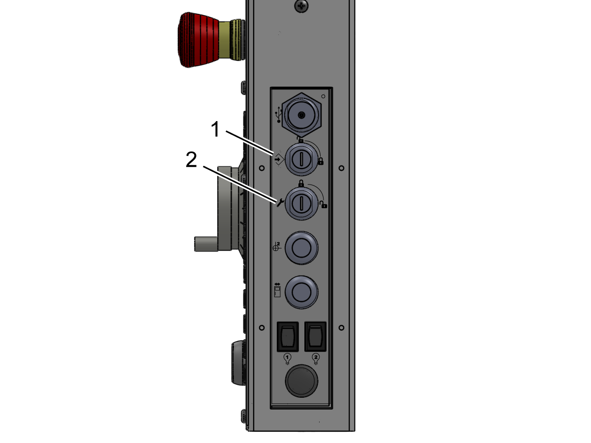
  • Preverite stikalo za zaklepanje pomnilnika, tako da preverite, da v nastavitvah ali programih ni mogoče spremeniti nastavitev ali programov [1].
  • Preizkusite stikalo za zagon / nastavitev, tako da preverite, ali se funkcije stroja v odklenjenem položaju lahko izvajajo v načinu nastavitve [2].
  • Preverite, ali sta nameščena Interlock in aktuator & kabel pravilno speljan.
  • Preverite, ali je okno (ali vrata za dostop do T / S) zapah je nameščen na vsakem stranskem oknu.
  • Preverite, ali se zapah zaskoči, da ohrani okno ali vrata v zgornjem položaju.
  • Preverite, ali okno ali vrata ključavnica je nameščena na vsakem stranskem oknu.
  • Preverite, ali okno ali vrata ključavnice zaprte v spodnjem položaju.
  • Preverite, ali vse ključavnice vrat stružnice delujejo kot zgoraj navedena okna in vrata.

17

Umerjanje avtomatskega prednastavitve orodja (ATP) 

  • Če vaša naprava vključuje možnost ATP, izvedite postopek umerjanja

Za navodila o izvedbi postopka kalibracije ATP glejte:

ATP kalibracija

18

WIPS-L Namestitev in kalibracija 

  • Če vaš stroj vsebuje možnost WIPS-L, namestite in izvedite postopek umerjanja

Za navodila o namestitvi in izvedbi postopka kalibracije WIPS-L glejte:

WIPS-L Namestitev
Kalibracija WIPS-L
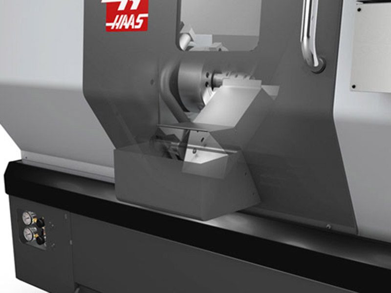
Parts Catcher. Product of Haas CNC machine tools.

19

Lovilec testnih delov (PCAT)

Če vaša naprava vključuje možnost PCAT, izvedite testni postopek.

  • Odprite TRENUTNE KOMANDE okno na nadzor
  • S smernimi tipkami se pomikate do naprav in do lovilca delov
  • Odpri vrata
  • Uporabite F2 za razširitev in izvlečenje lovilca delov
  • Preverite, ali se PCAT podaljša in vrne, ko so vrata odprta
  • Nato preverite PCAT se odpre in vrne, ko so vrata zaprta
  • Preverite, ali se vrata PCAT v celoti odpirajo s PCAT

  OPOMBA: Če PCAT med vračanjem trči na vrata, obvestite Haasa

20

Namestitev Wi-Fi kamere

  • Če vaša naprava vključuje možnost Wi-Fi Camera, izvedite postopek namestitve

Za navodila o izvedbi postopka namestitve kamere Wi-Fi glejte:

Namestitev Wi-Fi kamere

21

Namestitev mini transporterja

  • Če vaša naprava vključuje možnost mini transporterja, izvedite postopek namestitve

Za navodila o izvedbi postopka namestitve mini transporterja glejte:

Namestitev mini transporterja

22

Updated

Preizkusite C-os

Preizkus vpetosti C-osi:

  • Pritisnite [C] nato [HANDLE JOG] za orientacijo in vklop C-osi
  • Zavrtite JOG kolesce, da premaknete C-os.

Preizkus prekinitve C-osi:

  • Za vklop zavore vretena v načinu MDI vnesite ukaz M14, nato pritisnite [CYCLE START] , pri zaprtih vratih stroja. 
  • Odprite vrata in preverite, ali je vpenjalna glava zaklenjena v položaj
  • Če želite odklopiti zavoro, vnesite M15 v MDI. Zaprite vrata in nato pritisnite  [CYCLE START]

Načrt vzdrževanja stružnice

Naj bodo vaši Haas stroji v največji možni zmogljivosti, hkrati pa se izogibajte nenačrtovanim izpadom. Vzdrževalni program vam omogoča, da upravljate svoj urnik, ne pa da vas zasačijo nepravočasna presenečenja. Za priporočene intervale vzdrževanja glejte spodnjo povezavo.

Načrt vzdrževanja stružnice

3.2 Sidranje

Recently Updated

Navodila za sidranje (Drop-in ekspanzijsko sidro)


AD0456

Introduction

This procedure will show you how to install the Drop-In expansion style anchors to a Haas CNC.

NOTE: If the machine was built before Jan 2020 or is a VS or HDC series machine, please refer to the epoxy style anchoring procedure (AD0212) click here.

For instructions on how to anchor the various components for the Haas Cobot kits refer to the Haas Cobot - Anchoring instruction page.

This procedure applies to the following Service Kits:

Mill
Model Part Number
DC-1 93-1001018
DC-2 93-1001019
DC-4 93-1001211
DT/DM-1, DT/DM-2 93-1000601
DT/DM-3 93-1001136
EC-400/VC-400

93-1000567

See Note Below

EC-500/50 93-1001145
EC-1600/UMC-1600H 93-1000535
EC-630 93-1000856
GM-1 93-1001115
GM-1XT 93-1001235
GM-2-3AX 93-1000574
GM-2-5AX 93-1000542
GR-510 93-1000574
GR-712 93-1000574
MM/SMM Reboot 93-1001016
UMC-350HD 93-1000780
UMC-400/SS 93-1001224
UMC-500/SS 93-1000379
UMC-750/SS (NON REBOOT) 93-1000380
UMC-750/SS (REBOOT)  93-1001324
UMC-1000/SS (REBOOT) 93-1001324
UMC-1250/SS 93-1000644
UMC-1500-DUO/SS-DUO 93-1000871
VF-1/2, VF-2TR, VF-2SS 93-1000534
VF-2YT, VF-2SSYT, VM-2 93-1000549
 VF-3/3SS, VF-4/4SS 93-1000550
VF-3YT/3YTSS, VF-3YT/50, VF-5/40, VF-5/40TR, VF-5/40XT, VF-5SS, VF-5/50, VF-5/50TR, VF-5/50XT, VM-3, VMT-750 93-1000548
VF-6/40, VF-6SS, VF-6/40TR, VF-7/40, VF-6/50, VF-6/50TR, VF-7/50, VM-6 (Base with 8 leveling feet) Built between January 2020 and September 6th 2023 93-1000547
VF-8/40, VF-9/40, VF-8/50, VF-9/50, VR-8, VR-9 (Base with 8 leveling feet) Built between January 2020 and October 6th 2023 93-1000546
VF-10/40, VF-12/40, VF-10/50, VF-12/50 (Base with 8 leveling feet) 93-1000545
VF-11/40, VF-11/50, VR-11 (Base with 8 leveling feet) 93-1000544
VF-6/6TR/6SS/7/10/12 both 40T & 50T and VM-6 (Base with 6 leveling feet) Built September 7th 2023 and later 93-1000999
VF-8/9/11/14 both 40T & 50T and VR-8/9/11/14 (Base with 6 leveling feet) Built October 7th 2023 and later 93-1001000
VS-3 93-1000870
Updated
Note: For EC-400 anchor kit 93-1000567 only. EC-400 Anchor Template 96-0286 only permits 7 of the 8 anchor locations to be utilized. The anchor spot under the front door is inaccessible due to improper enclosure spacing. This is corrected with EC-400 Anchor Template 96-0286A, which shifts the front anchor location to a more accessible spot. 
 
Pallet Pool/RPL
Model Part Number
UMC-500PP 93-3526
UMC-750PP (V1) See Note Below
UMC-750PP (V2) 93-3527
UMC-1000PP (V2) 93-3527
UMC-1250PP See Note Below
EC-400PP 93-3525
VF-2YTPP See Note Below
VF-4 PP See Note Below
Robot Pallet Loader See Note Below
Note: There is currently no 93-xxxx service kit for the following models:
  • (30-12644B + 96-0316A) UMC-750 Pallet Pool (V1)
  • (30-12644B + 96-0364) VF-2YT Pallet Pool
  • (30-12644B + 96-0383) VF-4 Pallet Pool
  • (30-12644B + 96-0388) Robot Pallet Loader

You would need to order individual parts,  please contact your Local Haas Factory Outlet for availability.

Lathe
Model Part Number
ST-10/10Y/15/15Y 93-1000378
ST-10L/10LY/15L/15LY 93-1000855
ST-20/25/20Y/25Y 93-1000552
ST-20L/20LY/25L/25LY/28L/28LY 93-1001005
ST-30/35/30Y/35Y, DS-30Y (REBOOT ONLY) 93-1000541
ST-30L/35L/LY 93-1001079
ST-40 93-1000540
ST-40/40Y (Reboot) 93-1000819
ST-40L 93-1000539
ST-40L (Reboot) 93-1000820
ST-40S/45S/SY  93-1001012
ST-50/55 93-1000538
TL-1 93-1000537
TL-2 93-1000536
Extended Liner System
ST-10/10L/10Y/10LY 93-1000844
93-1000845

Tools required:

  • Paint markers
  • Painters Tape
  • Pipe cleaner brush
  • 5 lb. Sledge Hammer
  • SDS Plus Hammer Drill
    Note:  The SDS-Plus Hammer drill should be rated for 1" bit.

Video Instructions

Anchor Template Placement

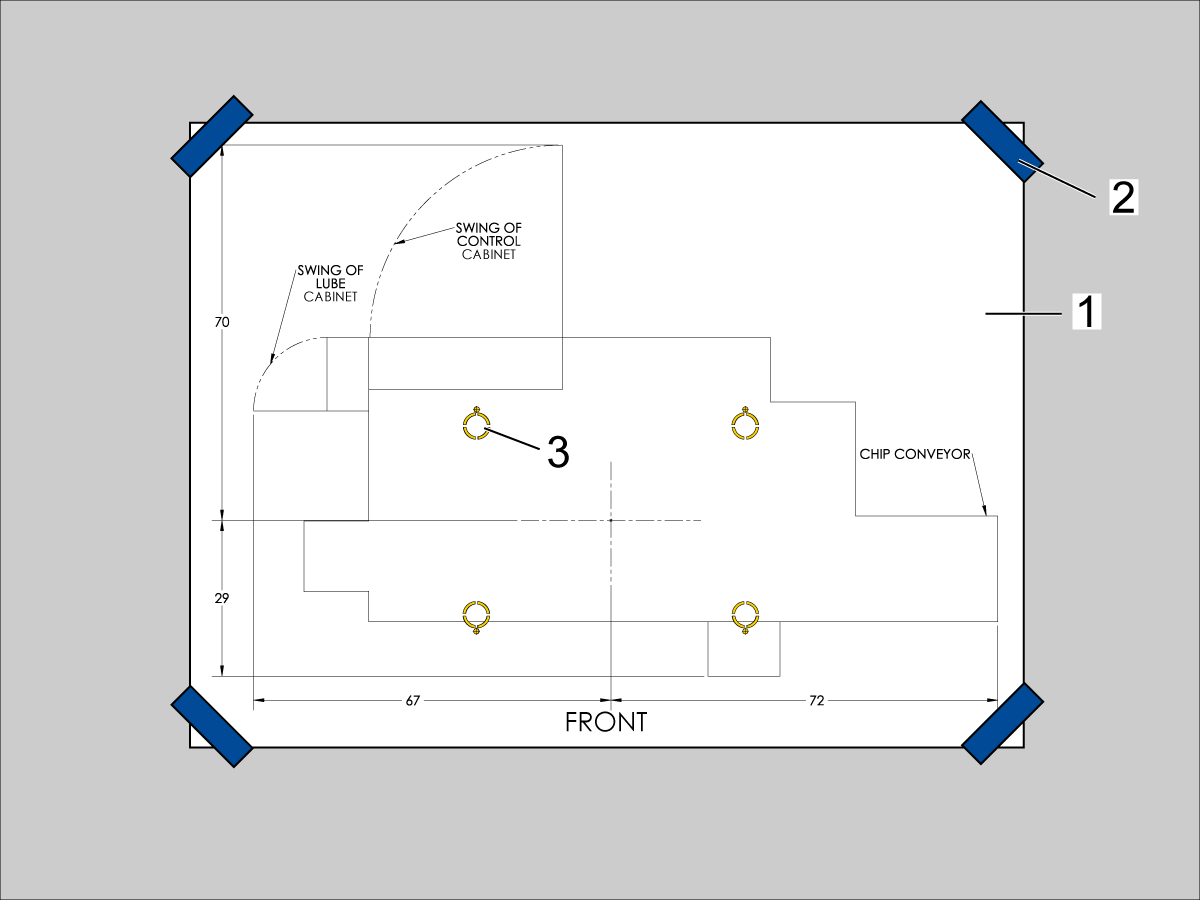
  1. Unroll machine anchoring template [1].
  2. Use centerlines and provided reference sheet dimensions, measure distances to nearest allowable obstructions.
  3. Once position is established, taped the corners [2] of the anchoring template to the foundation.  Keep the template as flat as possible.
  4. Spray paint the foundation in the cutout areas of the template [3].
  5. Let the paint dry for 5-10 minutes.
  6. Remove the anchoring template [1].

Drill Holes and Set the Anchors

Use the provided SDS-Plus Style drill for the following steps:

  • Drill specified number of 5/8" holes at depth 2.00 - 2.25" each.  
    • Drill bit should be perpendicular to foundation.
  • Clean the holes with pipe cleaner.
  • Use compressed air and a vacuum to clear holes.
  • Repeat for the number of leveling pads.
  • Cover the holes with tape to protect from unwanted debris while the other holes are drilled.
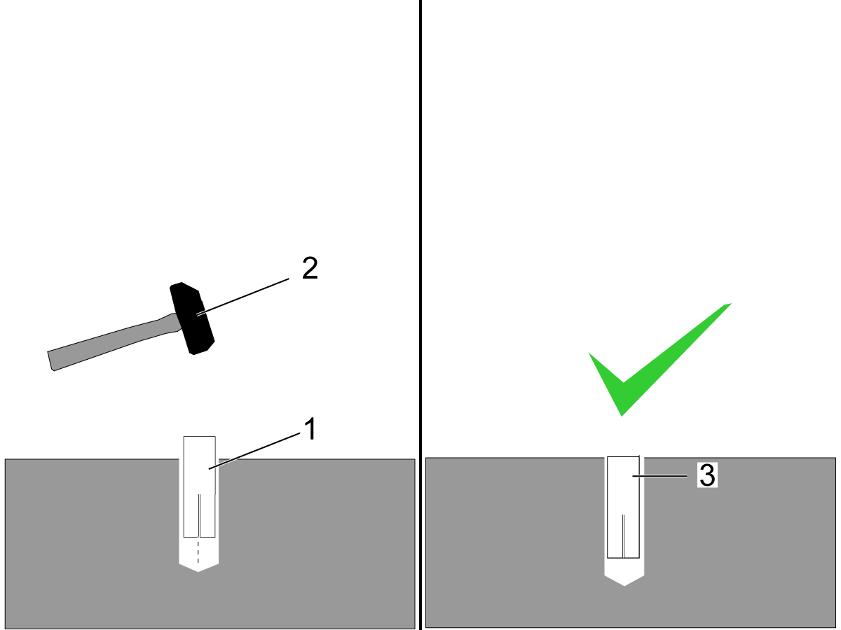
  • Using the hammer [2] set the drop-in anchor [1] flush with the concrete [3].

    Note:  Do not use the set tool to drive the anchor.  
  • Use the provided setting tool [1] and hammer [2], to seat the anchor in the concrete.
  • Make sure that the anchors are seated flush [3], use the setting tool as a gauge.
    Note:  Be careful not to overdrive the anchor [4] to far inside the hole.

Machine Placement

  1. Once the anchors are set, place the leveling pads on the spray painted cross-hairs.
  2. Place the machine on the leveling pads.
  3. Set the machine height.
  4. Level the machine
  5. Tighten down the machine locknuts.

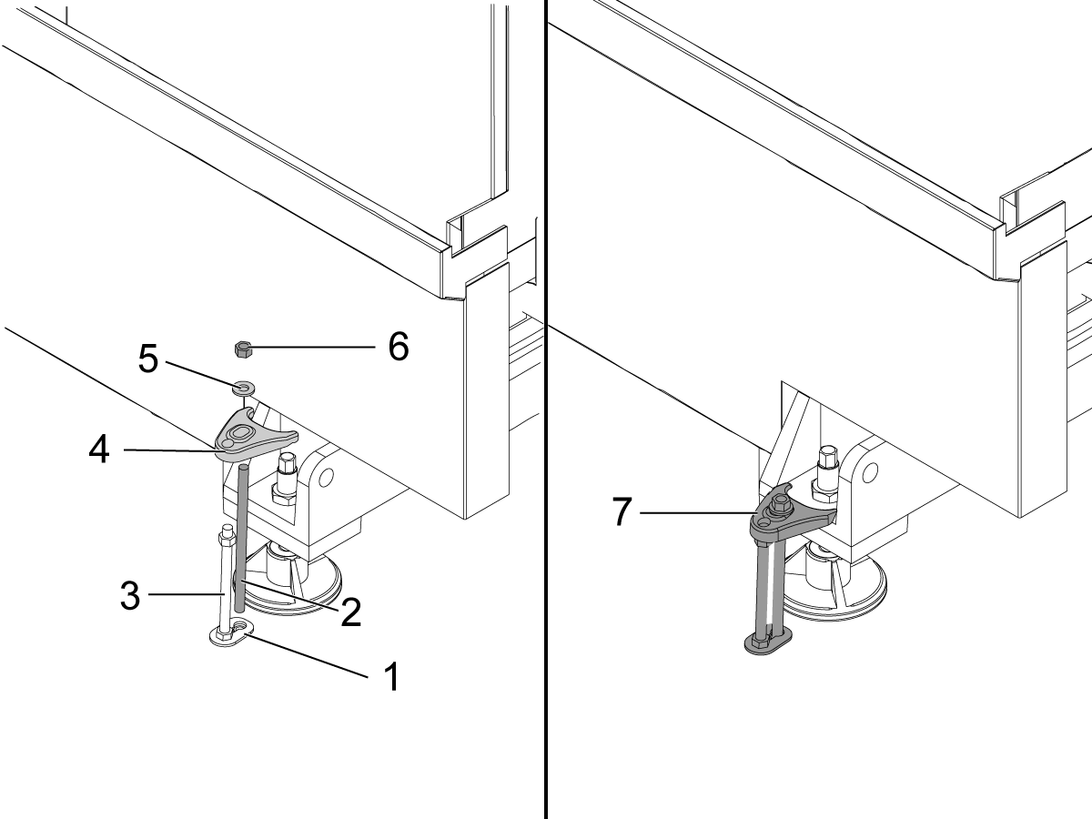
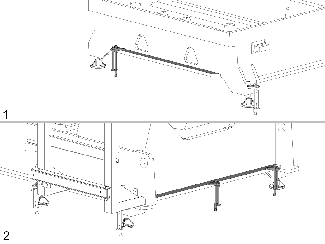
Anchoring Strap Installation

  1. Place the thrust plate flush [1] with the foundation.
  2. Thread stud [2] into the anchor location using two lock nuts.
  3. Place 1/2-13 hex nut on the 1/2-13 hex bolt [3] on top of the thrust plate.
  4. Place the anchoring strap [4].
  5. Place the washer [5] on the threaded rod.
  6. Thread the 1/2-13 hex nut [6] into the threaded rod.
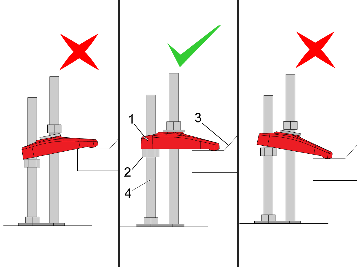
  7. Be sure the anchoring strap [7] remains parallel to the clamped casting surface.
  8. Torque 1/2-13 hex nut to 25ft-lbs (34 nm).

Make sure that the anchor strap [1] is level on the hex nut [2] and the machine base [3].

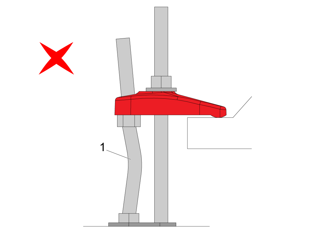
NOTE: Make sure the threaded stud [4] is perpendicular to the floor and not bent. 

Make sure the threaded stud welded to the base is not bent as shown in the image [1].

If this occurs make sure that the anchor holes are drilled straight and re-drill them if necessary. 

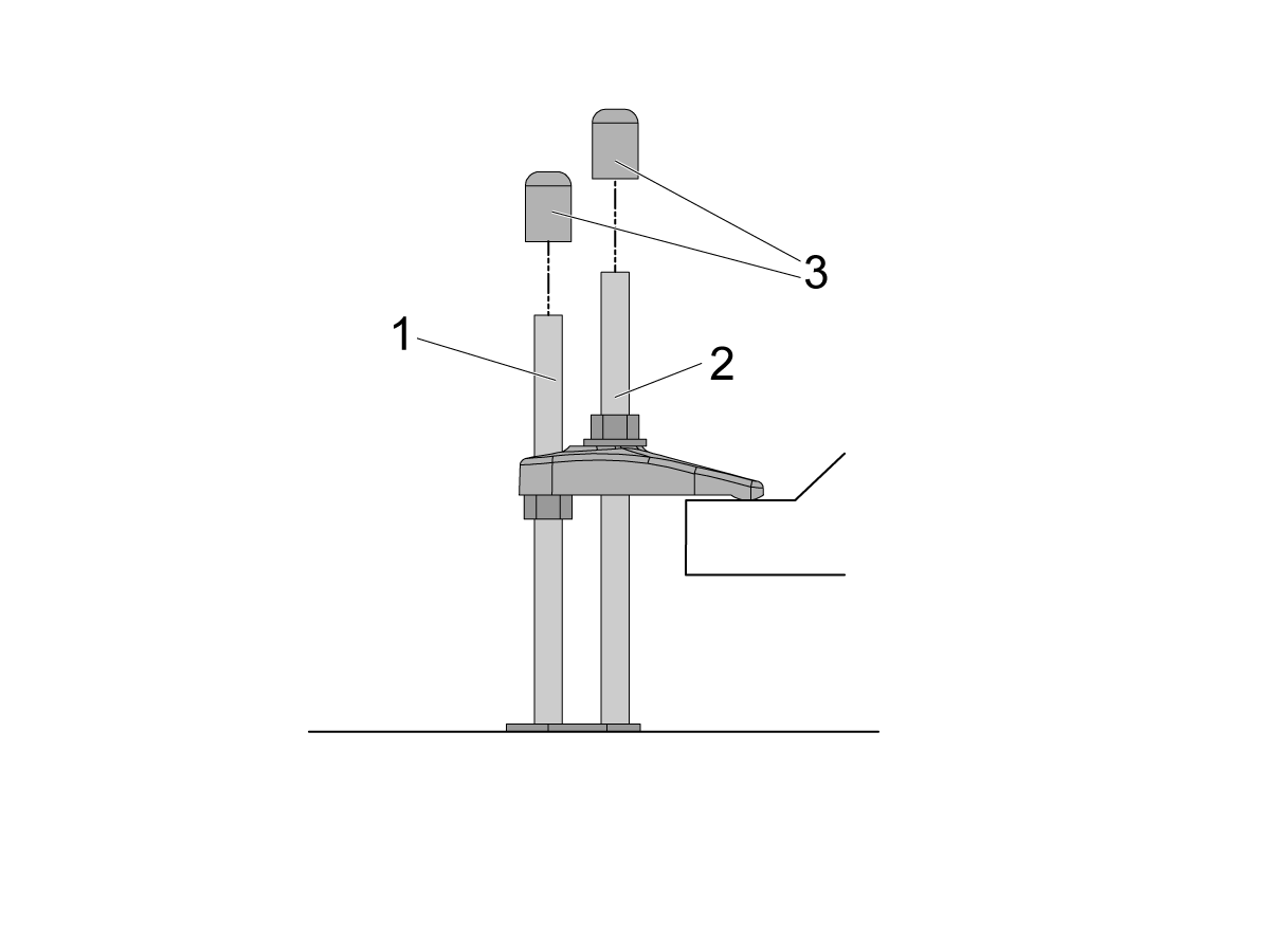
If there is clearance on the anchor [1] and stud [2] place the end caps [3] on the ends as shown in the image. Place these caps on all all anchors.

NOTE: The UMC-1250/SS does not have the anchoring fingers on the base foot. The indicated holes on the anchoring layout will have them anchoring down the base flange as shown in the image. Image [1] is the front of the machine, while image [2] is the back of the machine. 

Recently Viewed Items

You Have No Recently Viewed Items Yet

Povratne informacije
Haas Logo

HAAS dobavljena cena

Ta cena vključuje stroške pošiljanja, izvozne in uvozne dajatve ter vse druge stroške, ki nastanejo med pošiljanjem na lokacijo v Franciji, dogovorjeno z vami kot kupcem. Za dostavo CNC produkta Haas se ne sme zaračunati nobenih drugih obveznih stroškov.

BODITE OBVEŠČENI O NAJNOVEJŠIH NASVETIH IN TEHNOLOGIJI PODJETJA HAAS…

Prijavite se zdaj!   

HAAS TOOLING SPREJEMA NASLEDNJE:

  • Servis in podpora
  • Lastniki
  • Zahteva za servis
  • Priročniki za operaterja
  • Deli Haas
  • Zahteva za popravilo delilnika
  • Navodila za prednamestitev
  • Orodja za nakupovanje
  • Sestavi in preveri ceno novega Haas
  • Razpoložljiv inventar
  • Cenik Haas
  • Financiranje CNCA
  • O podjetju Haas
  • Izjava o dostopnosti
  • Izjava DNSH
  • Skladnost z izvoznimi predpisi
  • Zaposlitev
  • Certifikati in varnost
  • Kontaktirajte nas
  • Zgodovina
  • Pogoji in določbe
  • Pogoji in določbe Haas Tooling
  • Zasebnost
  • Garancija
  • Skupnost Haas
  • Certifikacijski program Haas
  • Motošport Haas
  • Fundacija Gena Haas
  • Haas skupnost za tehnično izobraževanje
  • Dogodki
  • Pridružite se pogovoru
  • Facebook
  • X
  • Flickr
  • YouTube
  • LinkedIn
  • Instagram
  • TikTok
© 2026 Haas Automation, Inc – Orodja CNC stroja

This site is protected by reCAPTCHA and the Google Privacy Policy and Terms of Service apply.

2800 Sturgis Rd., Oxnard, CA 93030 / Toll Free: 800-331-6746
Phone: 805-278-1800 / Fax: 805-278-2255