/2026-04-VOP-SquareComponent.jpg/_jcr_content/renditions/cq5dam.thumbnail.319.319.png) 增值选件套
增值选件套
 主轴
主轴
 刀库
刀库
 第 4 轴 |第 5 轴
 刀塔和动力刀
 探测
探测
 切屑和冷却液管理
 Haas 控制系统
 产品选项
产品选项
 刀具和夹具
刀具和夹具
 工件夹具
工件夹具
 5 轴解决方案
 自动化
自动化

修订版 E - 2026 年 6 月
此过程将介绍如何安装 ST 车床。
所需工具:
若要识别您的机床是否为重启机床,请参阅: ST 系列机床版本 - 识别
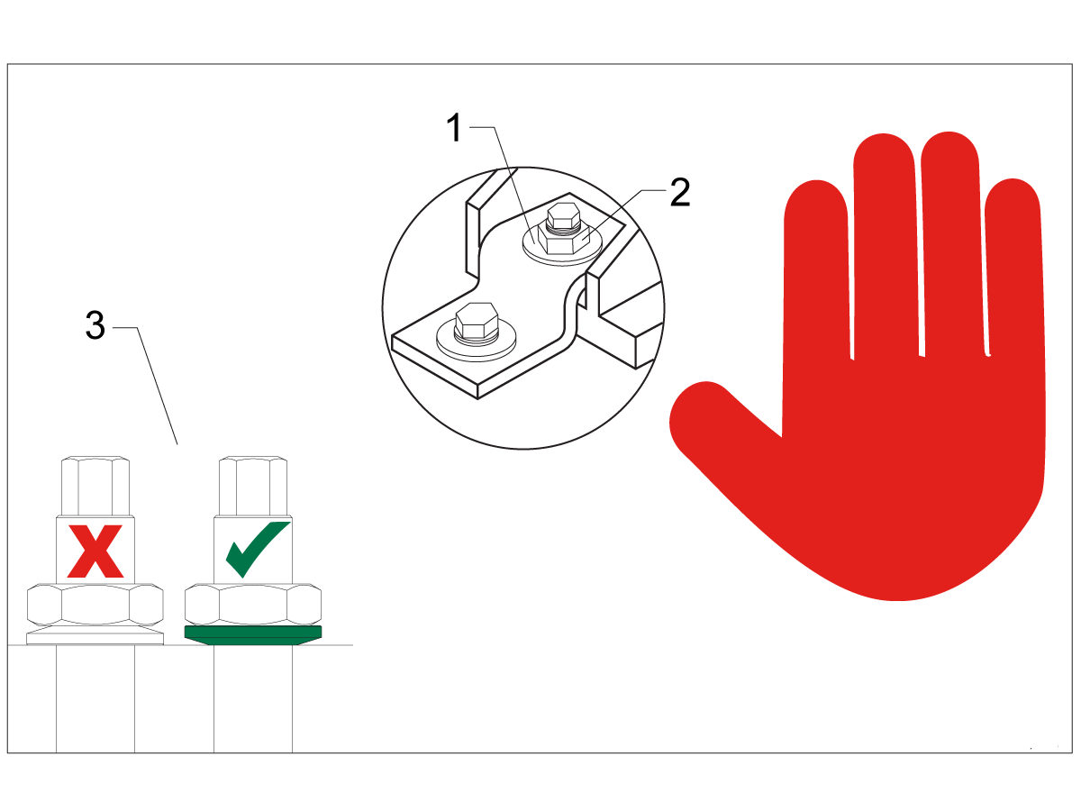
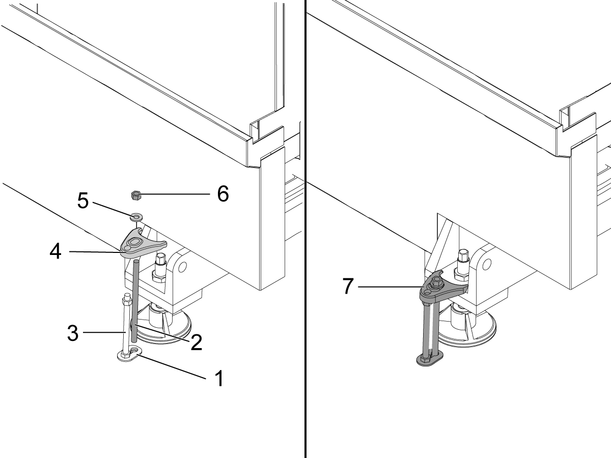
Note: The washers [1] and nuts [2] are installed during shipping and should be saved for installation and not be discarded.
Note: The washer orientation [3] is important. The conical part of the washer should be against the casting, see illustration.
To safely and effectively remove rust inhibitor from way covers and other non-painted surfaces:
Initial Scraping
Important: Do not use scotch-brite or metal scrapers, these will scratch the way covers.
Chemical Cleaning
Soak Time
Allow the cleaner to soak for several minutes to loosen remaining residue.
Wipe Down
Use a clean shop towel to thoroughly wipe off the softened rust inhibitor.
Rust Proofing
Apply mineral spirits or WD-40 to all exposed metal surfaces to prevent future rust formation.
Important: Always wear gloves and eye protection when handling chemical cleaners. Dispose of used towels and cleaning agents according to local environmental regulations.
Important: To avoid any contamination of the way cover seals with the sticky residue. Do not move any of the axes until all the rust inhibitor has been removed.
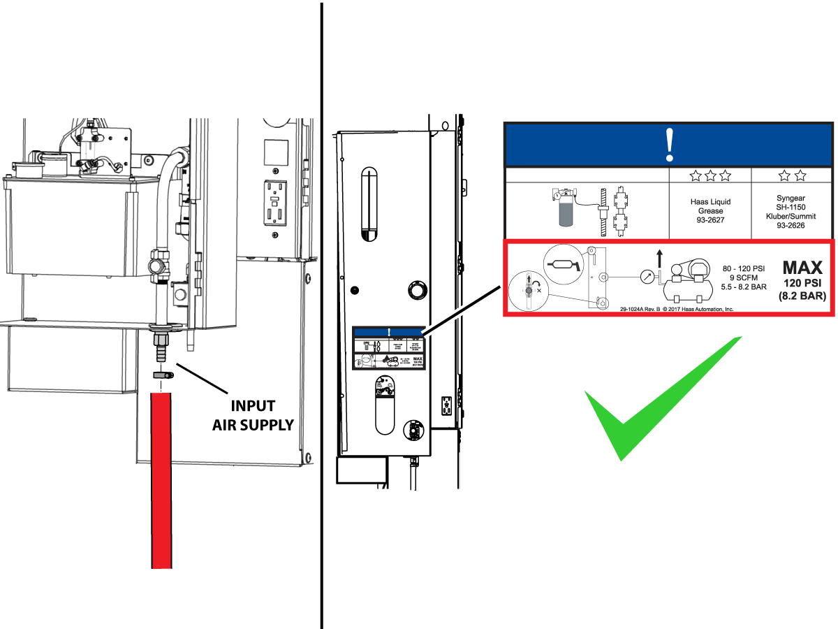
Connect the air supply at the lube panel.
Note: For air requirements refer to the decal that is located on the lube cabinet door.
Follow the Air Gun and Hose Installation procedure to install or replace the Air Gun.
Note: Some installation kits will come with a spare air gun assembly.
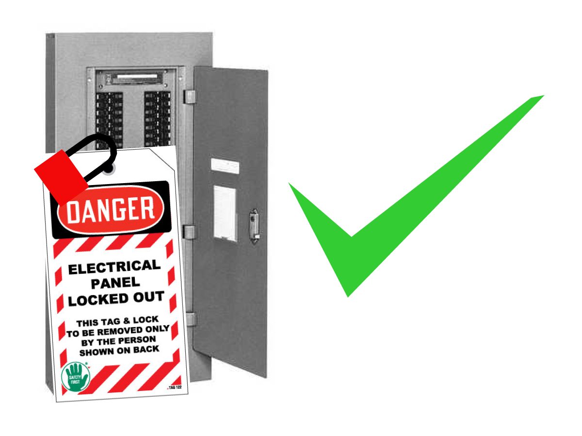
DANGER: Working with the electrical services required for CNC machines is extremely hazardous and can result in serious injury or death.
Before connecting line wires to the CNC:
If you are uncertain about how to safely disconnect power or perform LOTO procedures:
Failure to follow these precautions may result in electrical shock, equipment damage, or fatal injury.
Initial Control Inspection
Danger: At this point, there should be no electrical connection to the machine. Electrical panel must be closed and secured. When main switch is on, there is HIGH VOLTAGE throughout the electrical panel (including the circuit boards and logic circuits) and some components operate at high temperatures. Therefore, exercise extreme caution when working in the panel.
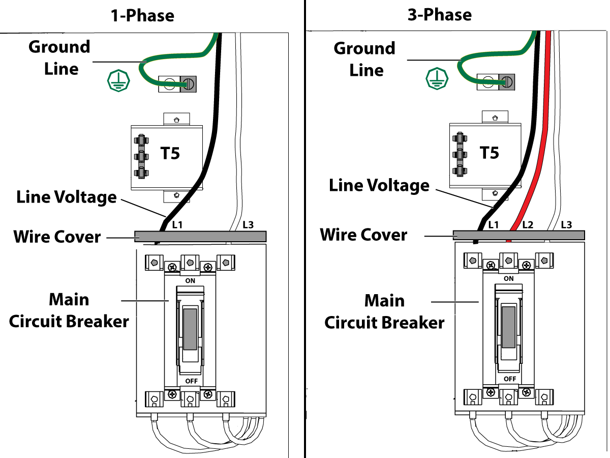
1-Phase Machines: Insert each power lead into the wire cover. Connect the two power leads to L1 and L3 terminals on top of the main circuit breaker.
3-Phase Machines: Insert each power lead into the wire cover. Connect the three power leads to L1, L2 and L3 terminals on top of the main circuit breaker.
Connect the separate ground line to the ground bus to the left of the terminals.
For 3-phase machines, check to see what type of power configuration is supplying the machine. Take voltage measurements of each power lead to ground line. Then refer to RD0084 - Input Power Configurations to determine which power lead should be connected to the L1 terminal based of the voltage readings and power configuration.
Refer to Haas Main Circuit Breaker - Torque Specifications for what value to torque the circuit breaker power leads.
Note: Make sure that the leads actually go into the terminal-block clamps . (A poor connection will cause the machine to run intermittently or have other problems, such as servo overloads.) To check, simply pull on the wires after the screws are tightened.
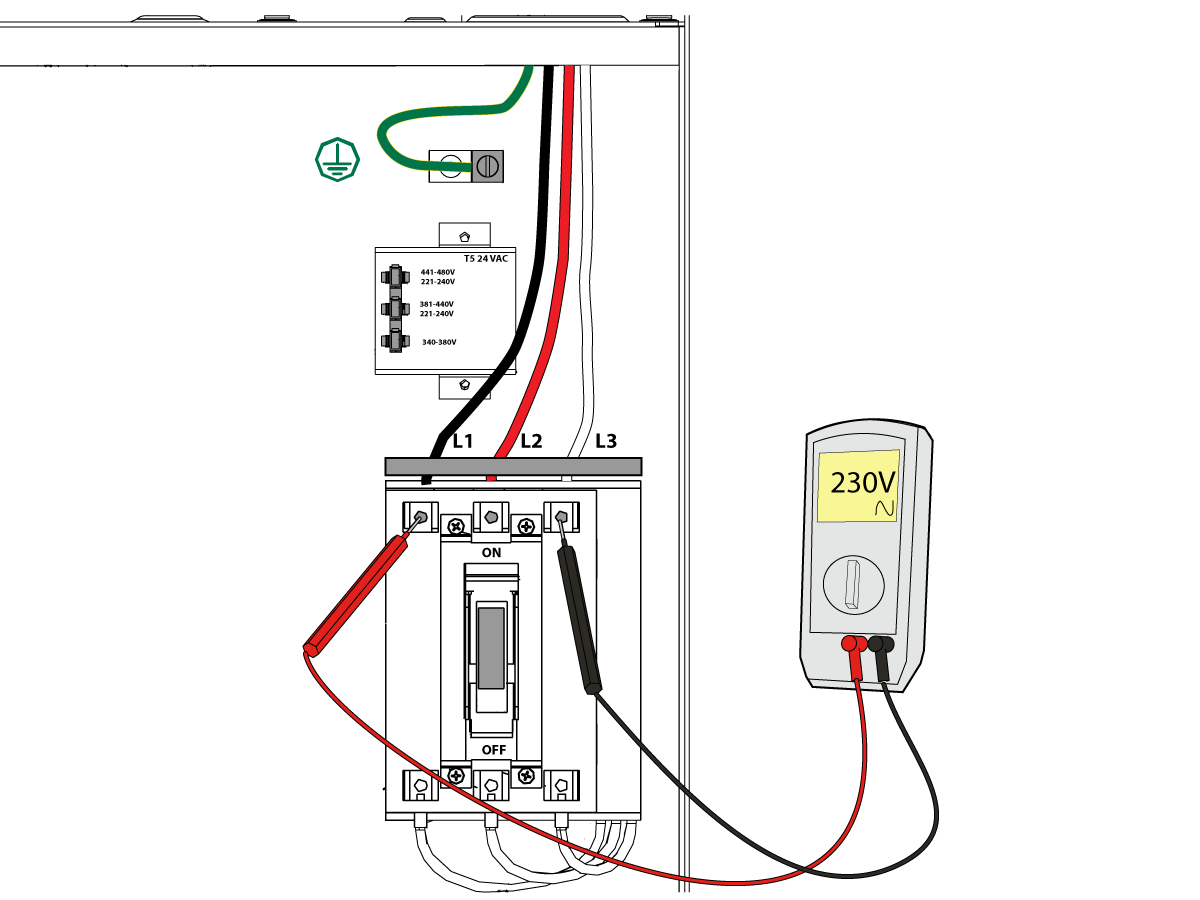
After the line voltage is connected to the machine, make sure that main circuit breaker (at top-right of rear cabinet) is OFF . Remove the Lockout / Tagout and Turn ON the power at the source. Using a digital voltmeter and appropriate safety procedures:
1-Phase Machines: Measure the AC voltage across L1 & L3 at the main circuit breaker. The AC voltage must be between 220 - 250 volts .
Note: Lower or higher than this voltage can generate low/high voltage alarms.
3-Phase Machines : Measure the AC voltage between all three pair phases at the main circuit breaker.
The AC voltage must be between 195 and 260 volts (360 and 480 volts for high voltage option).
SMinimill - Reboot: The AC voltage must be between 198 and 242 volts for machines without a high voltage transformer. Refer to the Minimill/SMinimill - Identification document.
Note: Wide voltage fluctuations are common in many industrial areas; minimum and maximum voltage supplied to a machine while it is in operation must be known. U.S. National Electrical Code specifies that machines should operate with a variation of +5% to -5% around an average supply voltage. If problems with line voltage occur, or low line voltage is suspected, an external transformer may be used. If you suspect voltage problems, voltage should be checked every hour or two during a typical day to be sure it does not fluctuate more than +5% or -5% from an average.
Important: With the main circuit breaker turned OFF.
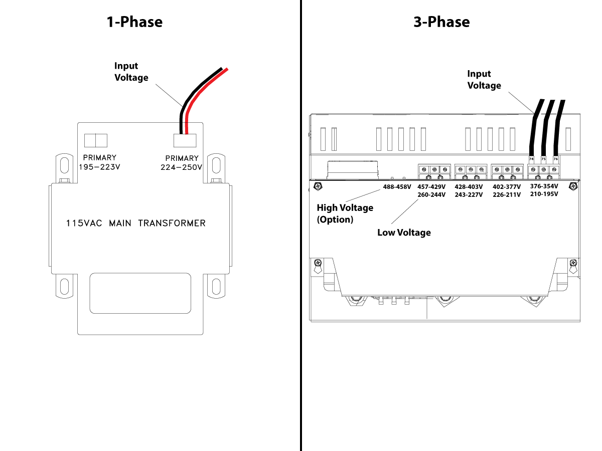
Check the transformer taps at the bottom-right corner of the rear cabinet.
1-Phase Machines: The input voltage cable must be moved to the connector which corresponds to the average voltage measured in the above step.
3-Phase Machines: The input voltage cables labeled 74, 75, and 76 must be moved to the terminal block triple which corresponds to the average voltage measured in the above step.
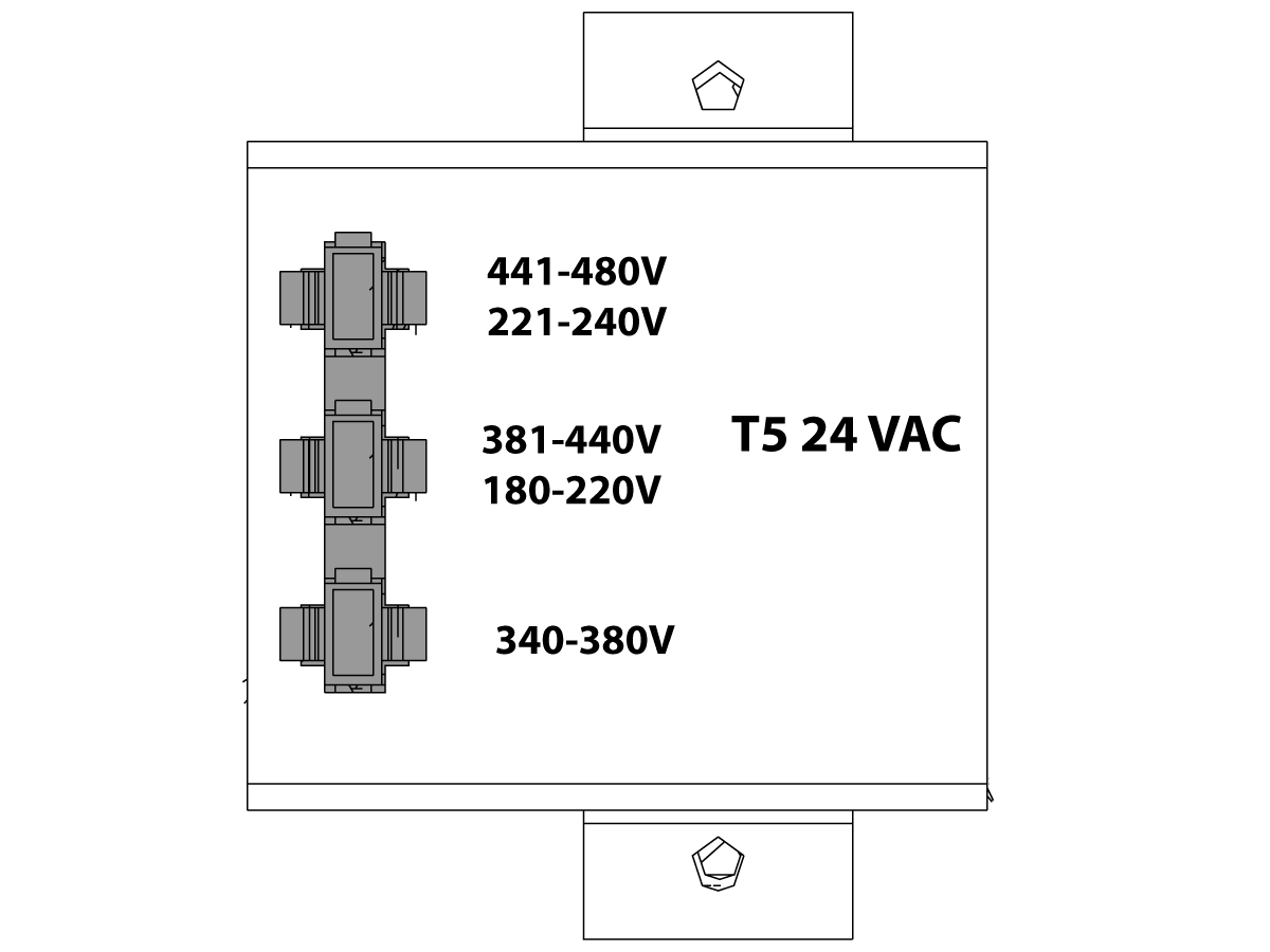
Transformer T5 supplies 24VAC used to power the main contactor. There are two versions of this transformer for use on a 240 and 400V machines. The 240V transformer has two input connectors located about two inches from the transformer, which allow it to be connected to either 180-220V or 221-240V.
Users that have 220V-240V RMS input power should use the connector labeled 221-240V, while users with 190-220V input power should use the connector labeled 180-220V. Failure to use the correct input connector will result in either overheating of the main contactor or failure to reliably engage the main contactor.
The 480V (option) T5 transformer has three input connectors, labeled 340-380V, 381-440V and 441-480V.
Users with 340-380V 50/60Hz power should use the 340-380V connector while users with 380V-440V 50/60Hz power should use the 381-440V connector.
Important: Set the main circuit breaker to ON. Check for evidence of problems, such as the smell of overheating components or smoke. If such problems are indicated, immediately set the main circuit breaker to OFF and call the factory before proceeding.
After the power is on, measure the voltage across the bottom terminals on the main circuit breaker. It should be the same as the measurements where the input power connects to the main breaker. If there are any problems, check the wiring.
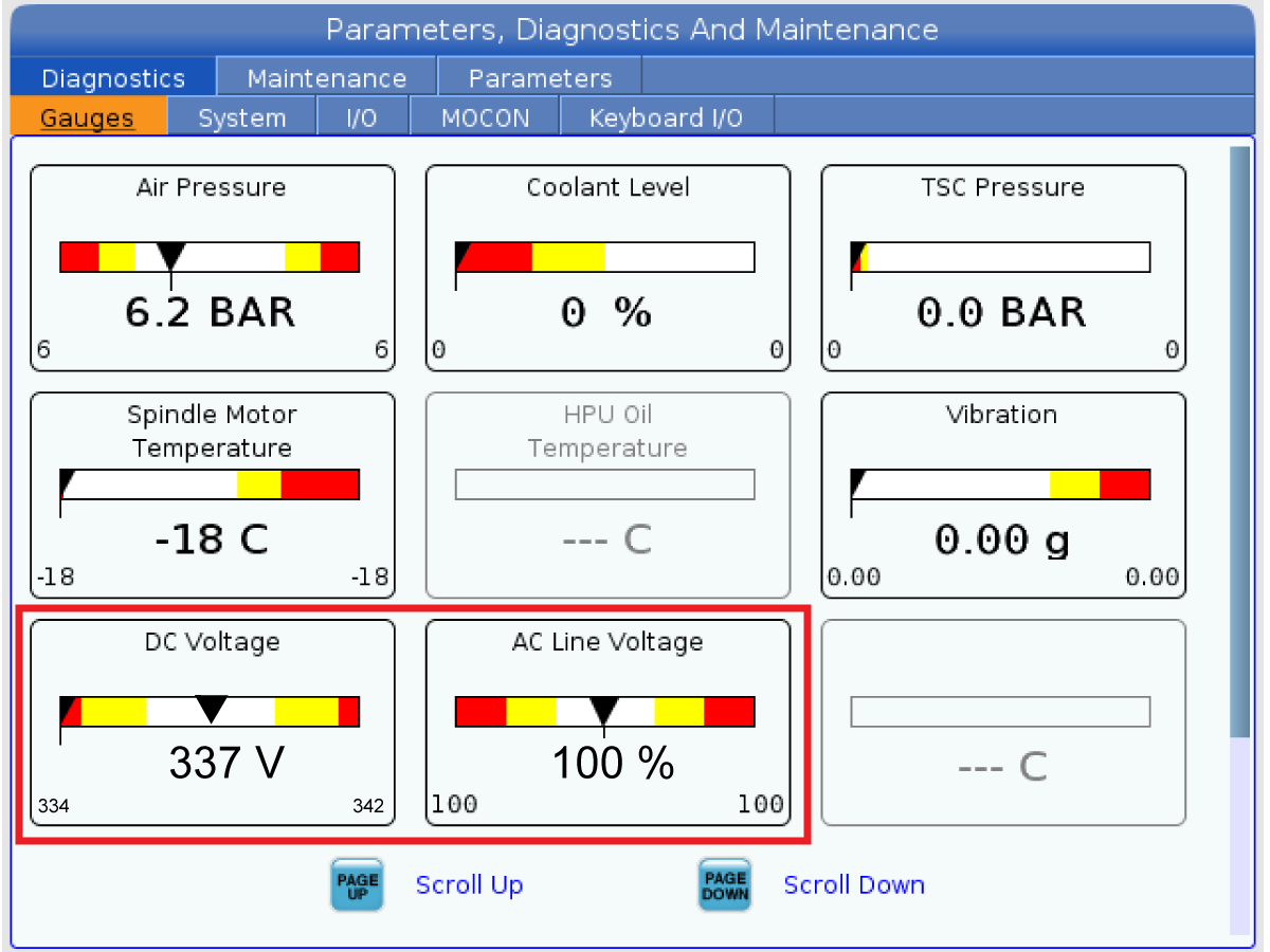
Apply power to the control by pressing the Power-On switch on the front panel.
Check the DC Voltage and AC Line Voltage gauges in Diagnostics. The DC Voltage gauge must read between 310 - 360V. The AC Line Voltage must be between 90 and 105 percent. If the voltage is outside these limits, turn off the power and recheck steps 2 and 3. If the voltage is still outside these limits, call the factory.
Electrical power must be phased properly to avoid damage to your equipment. The Power Supply Assembly PC board incorporates a "Phase Detect" circuit with neon indicators. When the orange neon is lit (NE5), the phasing is incorrect. If the green neon is lit (NE6), the phasing is correct. If both neon indicators are lit, you have a loose wire; check the connections. Adjust phasing by setting the source power to off and then swapping L1 and L2 of the incoming power lines at the main circuit breaker.
Danger: ALL POWER TO CNC MUST BE TURNED OFF LOCKOUT-TAGOUT AT THE SOURCE PRIOR TO ADJUSTING PHASING. ALWAYS DOUBLE CHECK THE INCOMING LINES WITH AN AC VOLTAGE DETECTOR.
Turn off the power and set the main circuit breaker to OFF. Close the door, lock the latches, and turn the power back on.
Remove the key from the control cabinet and give it to the shop manager.
Activation
When the machine is properly placed and connected to both air and electrical power, it is ready for final installation (removing shipping blocks, leveling, spindle sweep, etc.) and software activation. The HFO service technician does this. Contact the local HFO to schedule the work.
IMPORTANT: Machines equipped with motion sensors must be rough‑leveled before attempting to arm the motion sensor. For detailed instructions, refer to Service Notification - SA0007. Access to this document is restricted to Haas Factory Outlet personnel.
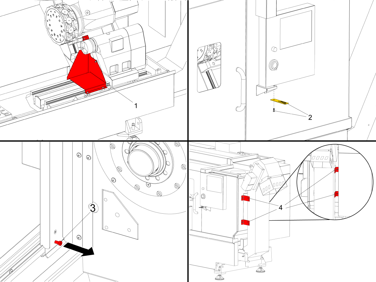
对于 ST-10-35 系列机床和 DS-30Y 车床
拆下刀塔以铸造装运支架 [1]。
拆下控制面板装运肩螺栓 [2]。带控制器机柜的机床的装运支架位于控制器的右侧。
拆下门装运肩螺栓 [3]。
拆下排屑器支架 [4]。用装运支架螺钉插入螺纹钣金孔。
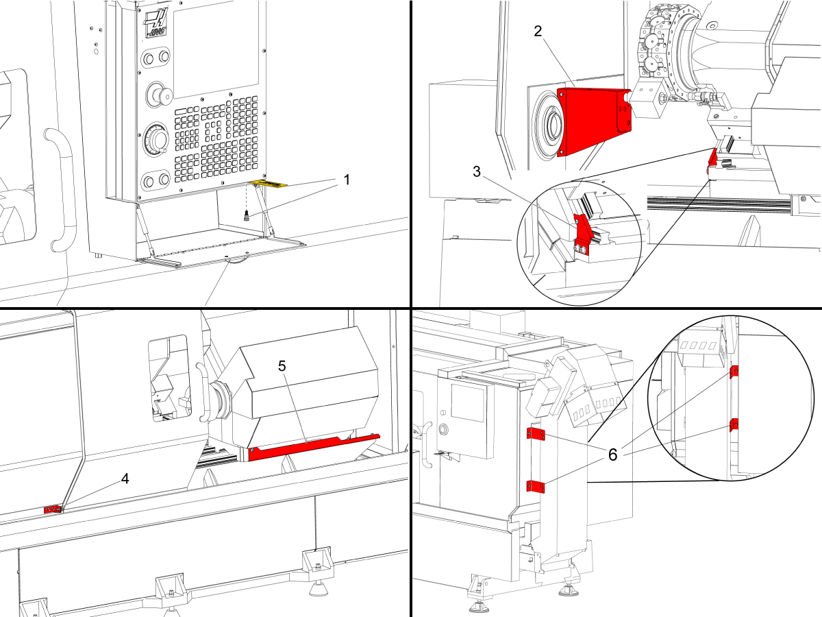
用于预重启 ST-30/35/DS-30Y 车床
拆下控制面板装运肩螺栓 [1]。
拆下刀塔到主轴装运支架 [2]。
拆下 Y 轴装运支架 [3]。
拆下操作门装运支架 [4]。
拆下第二个主轴装运支架 [5]。参阅 DS 运输支架拆卸 AD0065。
拆下排屑器支架 [6]。
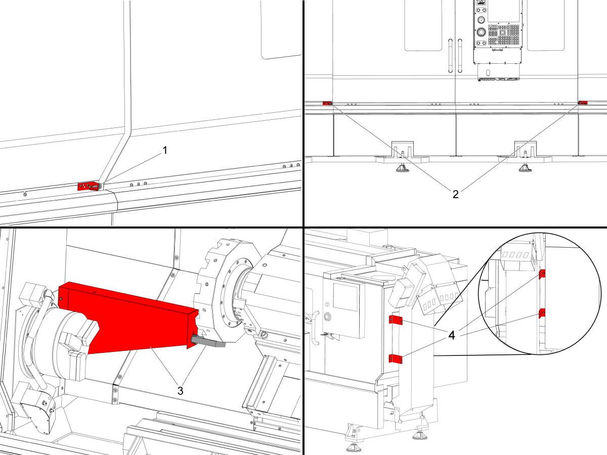
适用于预重启 ST-40/40L/45/45L/50/55 车床
拆除装运箱架。对于 ST-40/45,有一个支架。对于 ST-40L/45L/50/55,有两个支架[1,2]。
拆下刀塔到主轴装运支架 [3]。
拆下排屑器支架 [4]。
将控制器安装到机床上。
有关如何安装控制器的指南,请参阅:
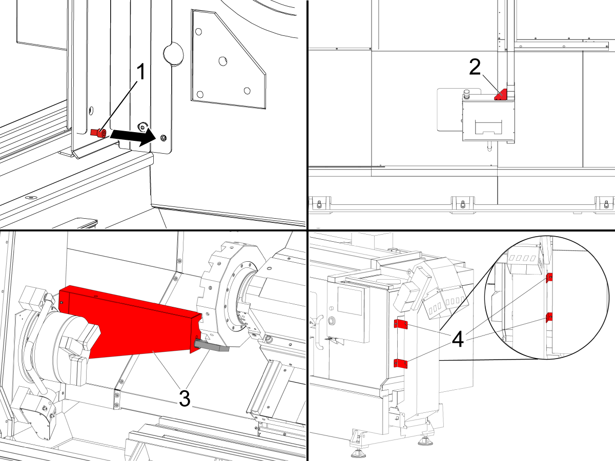
对于 ST-40-55 系列重启机床和 DS-40Y 机床:
拆下门装运肩螺栓 [1]。
拆下控制器装运支架 [2]。
拆下刀塔到主轴装运支架 [3]。
拆下排屑器支架 [4]。
注意:若要区分 ST- 预重启车床和重新启动机床,请参阅 ST 系列机床版本 - 识别。

对于 DS-40Y 机床:
拆下第二个主轴装运支架[1]。
每次将一个轴归零或按 [POWER UP]。完成调平过程。
重复这些步骤以达到正确的机器水平。
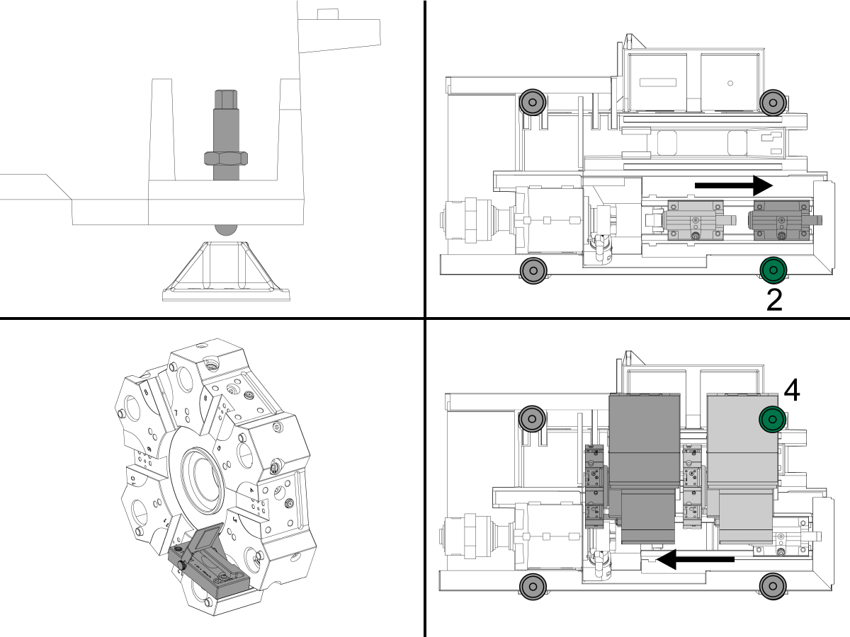
使用 (4) 角调平螺钉将机器高度设置为离地 3.0"。转动每个螺钉,使其具有相等的张力。
升起螺钉 2,使其离开垫。
将尾座或第二个主轴移到其机床原点。
将工具 T-2181A 安装到刀塔上,使其与地面平行。
将刀塔旋转到 X 轴的中心,然后尽可能在 Z 轴上向主轴倾斜。
查看与 Z 轴平行的较小水平,并升起或降低螺钉 4 以居中气泡。
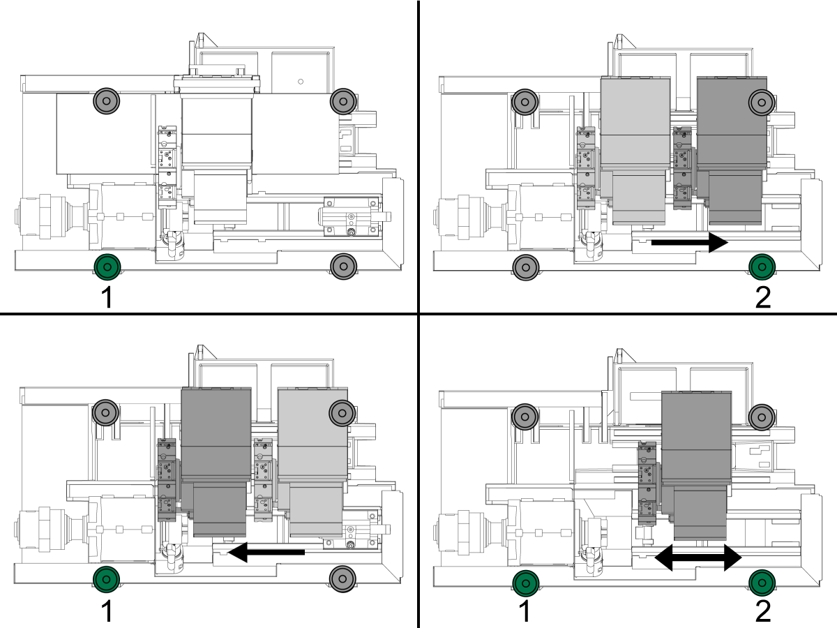
现在,看看与刀塔面平行的较大水平,并升起或降低螺钉 1 以居中气泡。
要检查机器中的扭曲情况,请沿 Z 轴将刀塔移回本机位置。
使用更大的水平提升或较低的螺钉 2 将气泡居中,等待 10 秒,让气泡稳定下来。
尽可能将转塔移回主轴,并升高或降低螺钉 1 以居中气泡。继续将刀塔从主位置移到主轴位置,并调整螺钉 1 和 2,直到拆下扭曲。
拧紧锁紧螺母,确保不会升高或降低螺钉。
通过沿 Z 轴移动刀塔并检查是否扭曲并继续调整直至水平,验证机器是否处于水平。
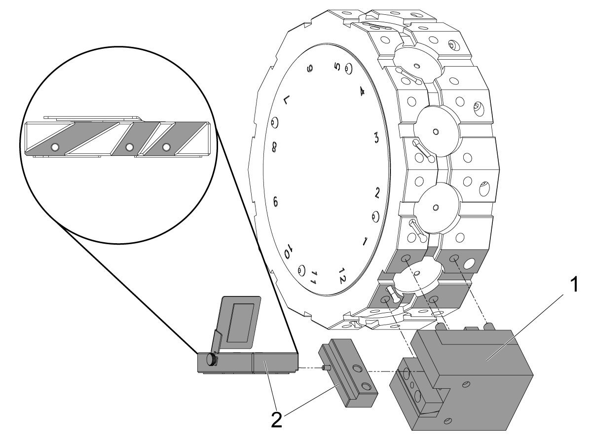
每次将一个轴归零或按[POWER UP]。完成调平过程。重复这些步骤以达到正确的机器水平。
注意:如果您的机床设备配备了 BMT 刀塔,则将 BMT65OD-1 刀架[1]安装至刀套 1 内。组装 T-2181A [2]使水平面与地面平行。根据机床设备的楔角,共配备三个插槽。用刀架夹住水平仪,或用千斤顶螺杆固定至刀架内的水平位置。
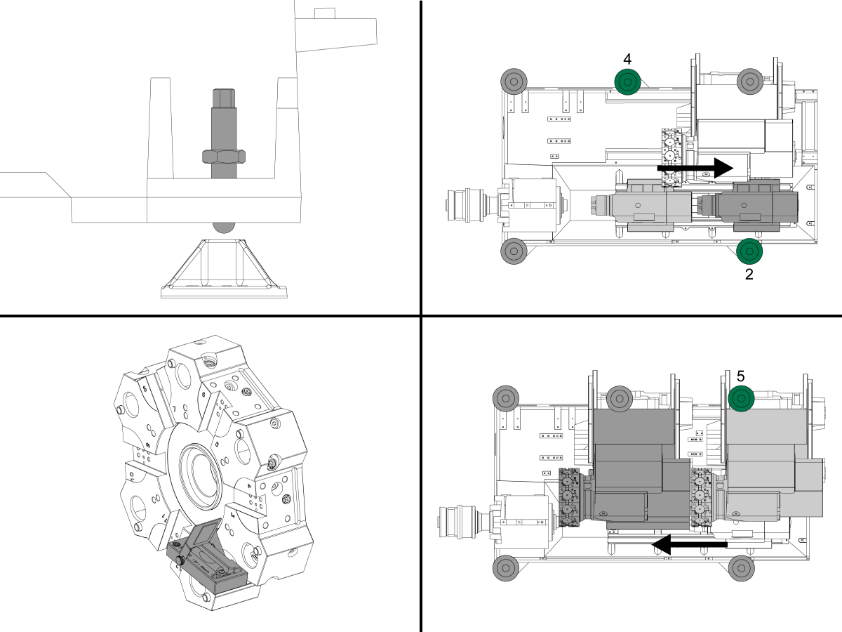
使用 (4) 角调平螺钉将机器高度设置为离地 3.0"。转动每个螺钉,使其具有相等的张力。
升起螺钉 2 和 4,使其离开垫片。
将尾座或第二个主轴移到其机床原点。
将工具 T-2181A 安装到刀塔上,使其与地面平行。
将刀塔旋转到 X 轴的中心,然后尽可能在 Z 轴上向主轴倾斜。
查看与 Z 轴平行的较小水平,并升起或降低螺钉 5 以居中气泡。
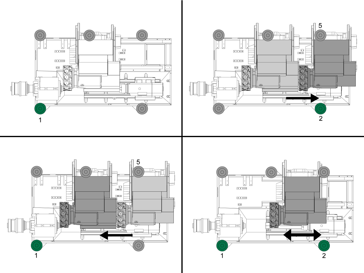
现在,看看与刀塔面平行的较大水平,并升起或降低螺钉 1 以居中气泡。
要检查机器中的扭曲情况,请沿 Z 轴将刀塔移回本机位置。
使用更大的水平提升或较低的螺钉 2 将气泡居中,等待 10 秒,让气泡稳定下来。.
尽可能将转塔移回主轴,并升高或降低螺钉 1 以居中气泡。继续将刀塔从主位置移到主轴,并调整螺钉 1 和 2,直到拆下扭曲。
将螺钉 4 用手拧到垫上,使用扳手,仅拧紧 10°。
不要进一步拧紧,因为您将更改机器的级别。
拧紧锁紧螺母,确保不会升高或降低螺钉。
通过沿 Z 轴移动刀塔并检查是否扭曲并继续调整直至水平,验证机器是否处于水平。
每次将一个轴归零或按 [POWER UP]。完成调平过程。重复这些步骤以达到正确的机器水平。
注意: 如果您的机床设备配备了 BMT 刀塔,则将 BMT OD-1 刀座[1]安装至刀套 1 内。组装 T-2181A [2]使水平面与地面平行。根据机床设备的楔角,共配备三个插槽。用刀架夹住水平仪,或用千斤顶螺杆固定至刀架内的水平位置。
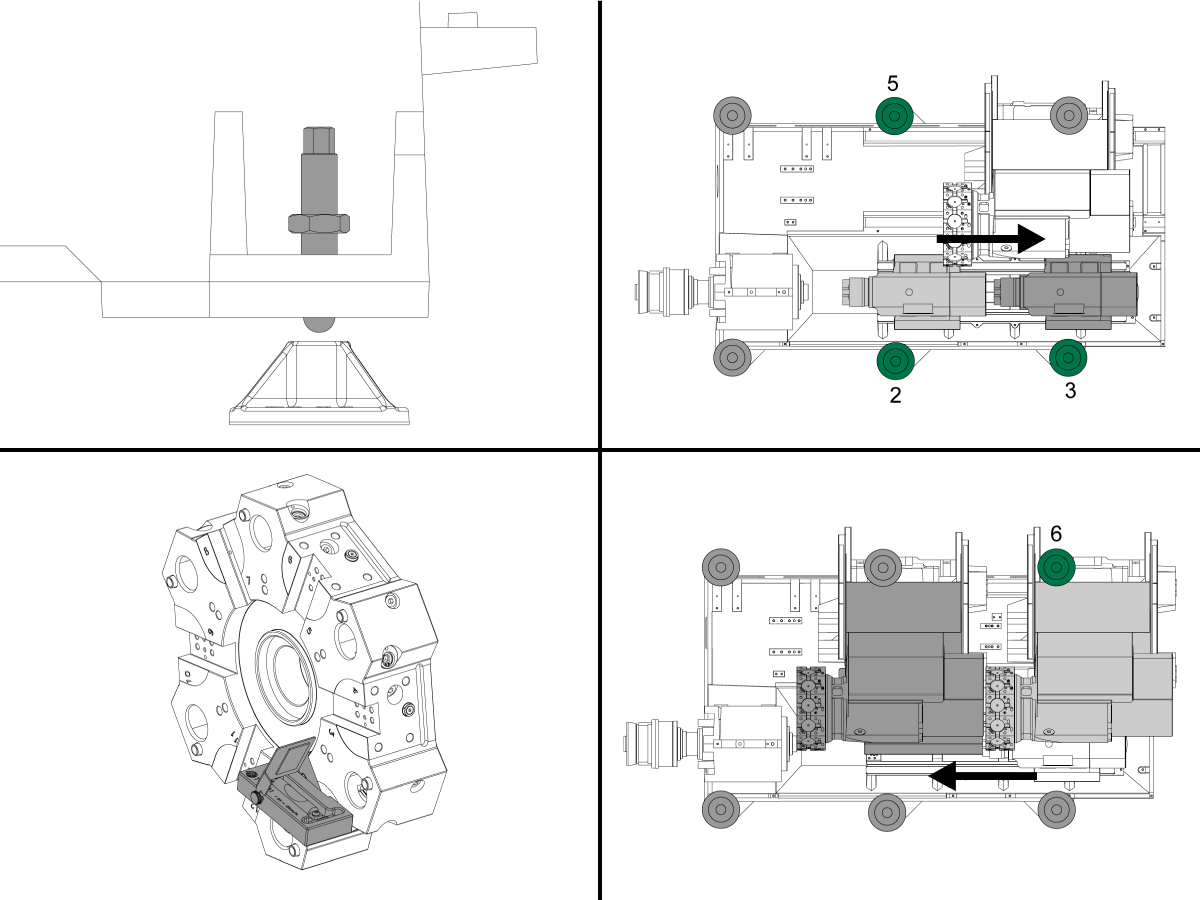
使用 (4) 角调平螺钉将机器高度设置为离地 3.0"。转动每个螺钉,使其具有相等的张力。
升起螺钉 2、3 和 5,使其离开垫片。
将尾座或第二个主轴移到其机床原点
将工具 T-2181A 安装到刀塔上,使其与地面平行。
将刀塔旋转到 X 轴的中心,然后尽可能在 Z 轴上向主轴倾斜。
查看与 Z 轴平行的较小水平,并升起或降低螺钉 6 以居中气泡。
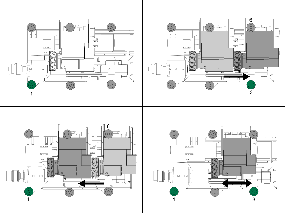
现在,看看与刀塔面平行的较大水平,并升起或降低螺钉 1 以居中气泡。
要检查机器中的扭曲情况,请沿 Z 轴将刀塔移回本机位置。
使用更大的水平提升或较低的螺钉 3 将气泡居中,等待 10 秒,让气泡稳定下来。.
尽可能将转塔移回主轴,并升高或降低螺钉 1 以居中气泡。继续将刀塔从主位置移到主轴,并调整螺钉 1 和 3,直到拆下扭曲。
用手将螺钉 2 和 5 降至垫上,并使用扳手,仅拧紧 10°。
不要进一步拧紧,因为您将更改机器的级别。
拧紧锁紧螺母,确保不会升高或降低螺钉。
通过沿 Z 轴移动刀塔并检查是否扭曲并继续调整直至水平,验证机器是否处于水平。
每次将一个轴归零或按 [POWER UP]。完成调平过程。
重复这些步骤以达到正确的机器水平。
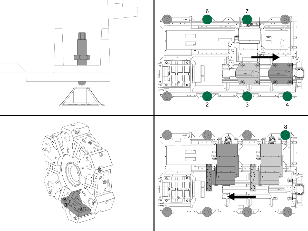
使用 (4) 角调平螺钉将机器高度设置为离地 3.0"。转动每个螺钉,使其具有相等的张力。
升起螺钉 2、3、4、6 和 7,使其离开垫片。
将尾座或第二个主轴移到其机床原点
将工具 T-2181A 安装到刀塔上,使其与地面平行。
将刀塔旋转到 X 轴的中心,然后尽可能在 Z 轴上向主轴倾斜。
查看与 Z 轴平行的较小水平,并升起或降低螺钉 8 以居中气泡。
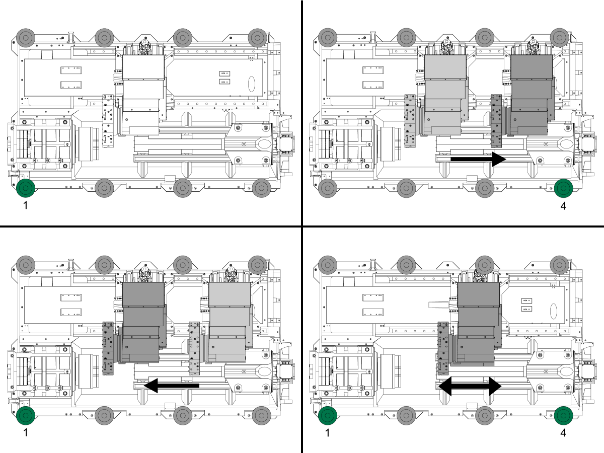
现在,看看与刀塔面平行的较大水平,并升起或降低螺钉 1 以居中气泡。
要检查机器中的扭曲情况,请沿 Z 轴将刀塔移回本机位置。
使用更大的水平提升或较低的螺钉 4 将气泡居中,等待 10 秒,让气泡稳定下来。.
尽可能将转塔移回主轴,并升高或降低螺钉 1 以居中气泡。继续将刀塔从主位置移到主轴,并调整螺钉 1 和 4,直到拆下扭曲。
将螺钉 2、3、6 和 7 手动固定到垫上,然后使用扳手,仅拧紧 10°。
不要进一步拧紧,因为您将更改机器的级别。
拧紧锁紧螺母,确保不会升高或降低螺钉。
通过沿 Z 轴移动刀塔并检查是否扭曲并继续调整直至水平,验证机器是否处于水平。
Run the spindle run-in program.
Note: For 10K spindles and above use a balanced tool holder
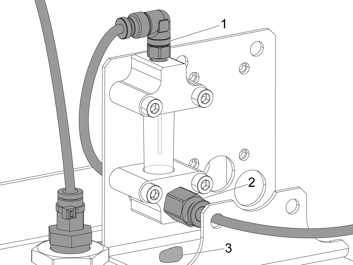
Examine the sight glass, make sure the correct number of drops are fall through the sight glass.
Examine the fittings [1,2] on top of the oil pump tank.
The oil collects on top of the oil pump tank [3] either behind or in front of the sight glass bracket, underneath the leaking fitting.
Tighten any leaking fittings.
Go to the Maintenance tab.
Press [F2] to cycle an axis lubrication test.
Inspect the gauge on the lubrication system. Make sure it holds pressure.
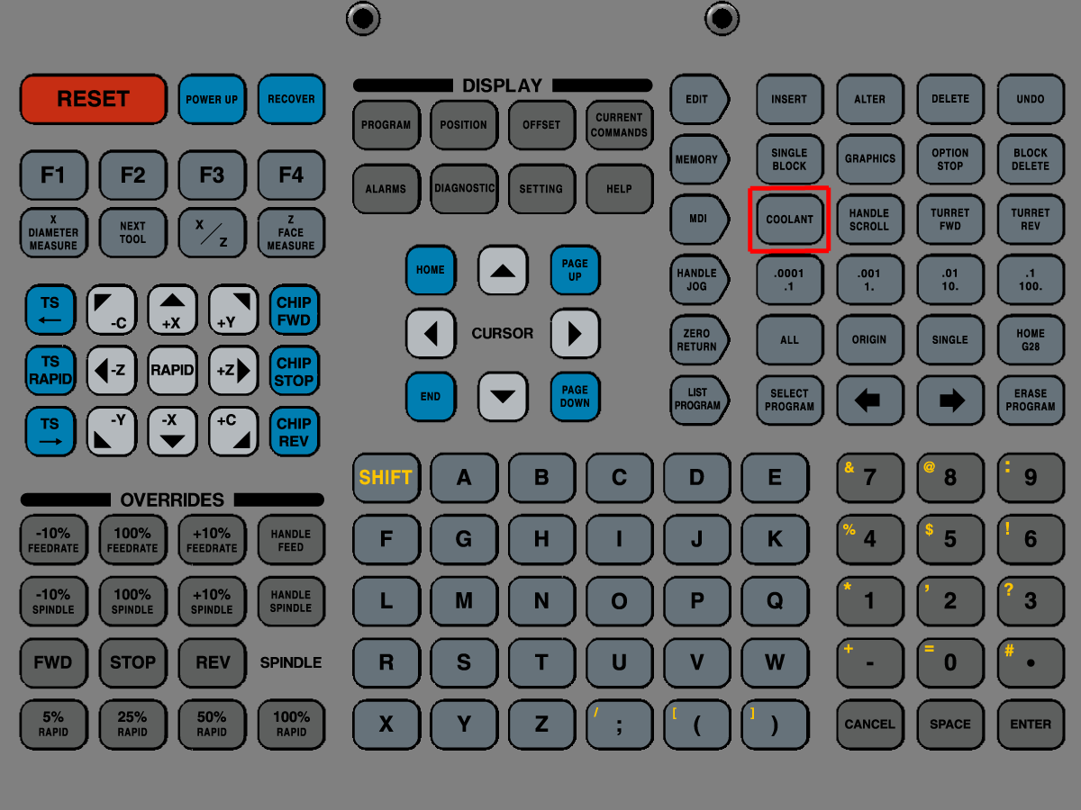
测试冷却液操作 - 多级冷却液泵
如果您的机床配备多级冷却液泵,请执行以下操作:
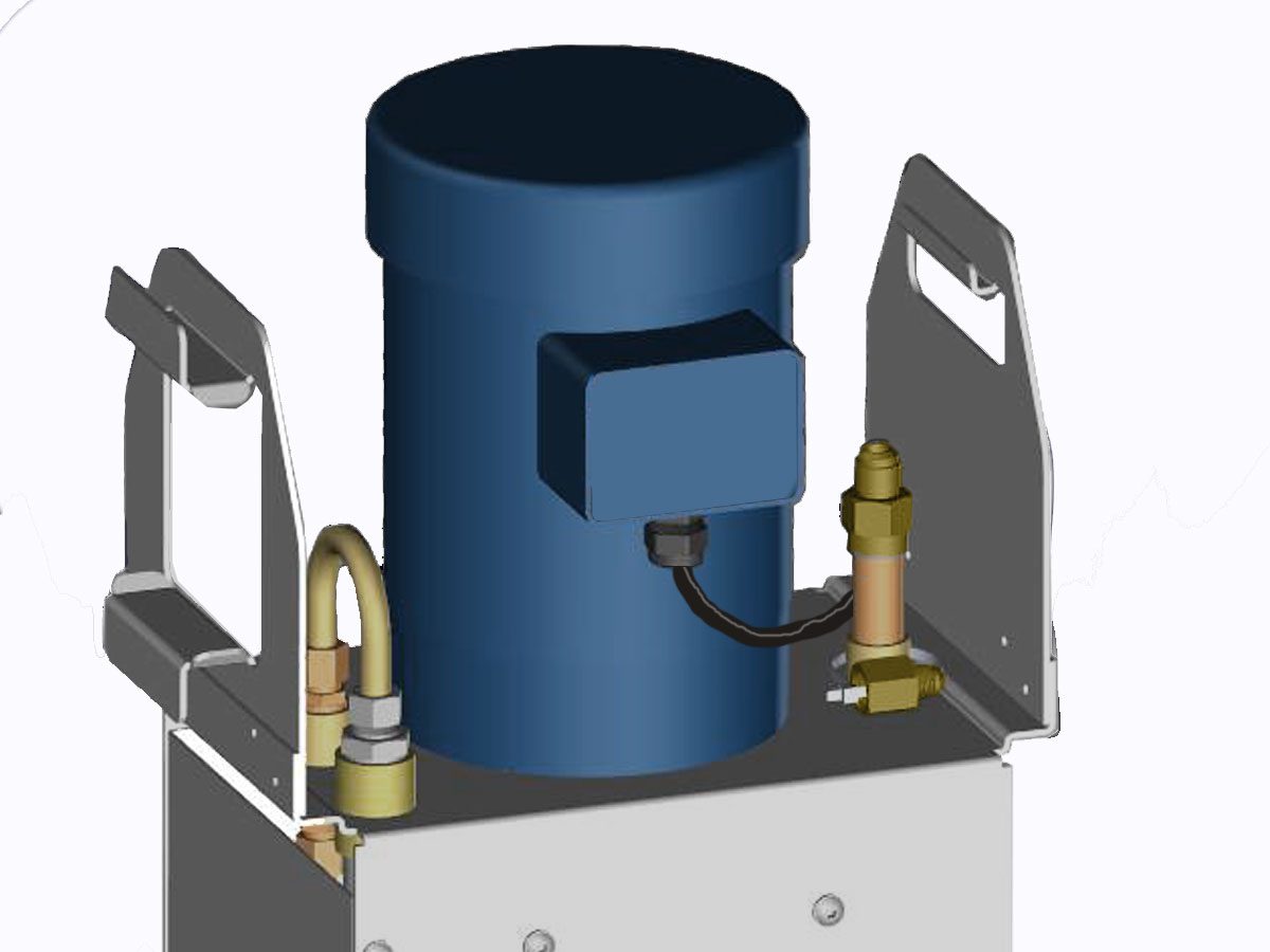
测试高压冷却液 (HPC) 操作
如果您的机床配备了高压冷却液系统,请执行以下操作:
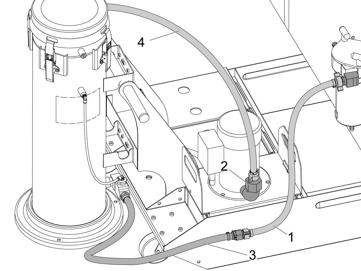
辅助冷却液过滤器安装
有关如何执行辅助冷却液过滤器安装过程的指南,请参阅:
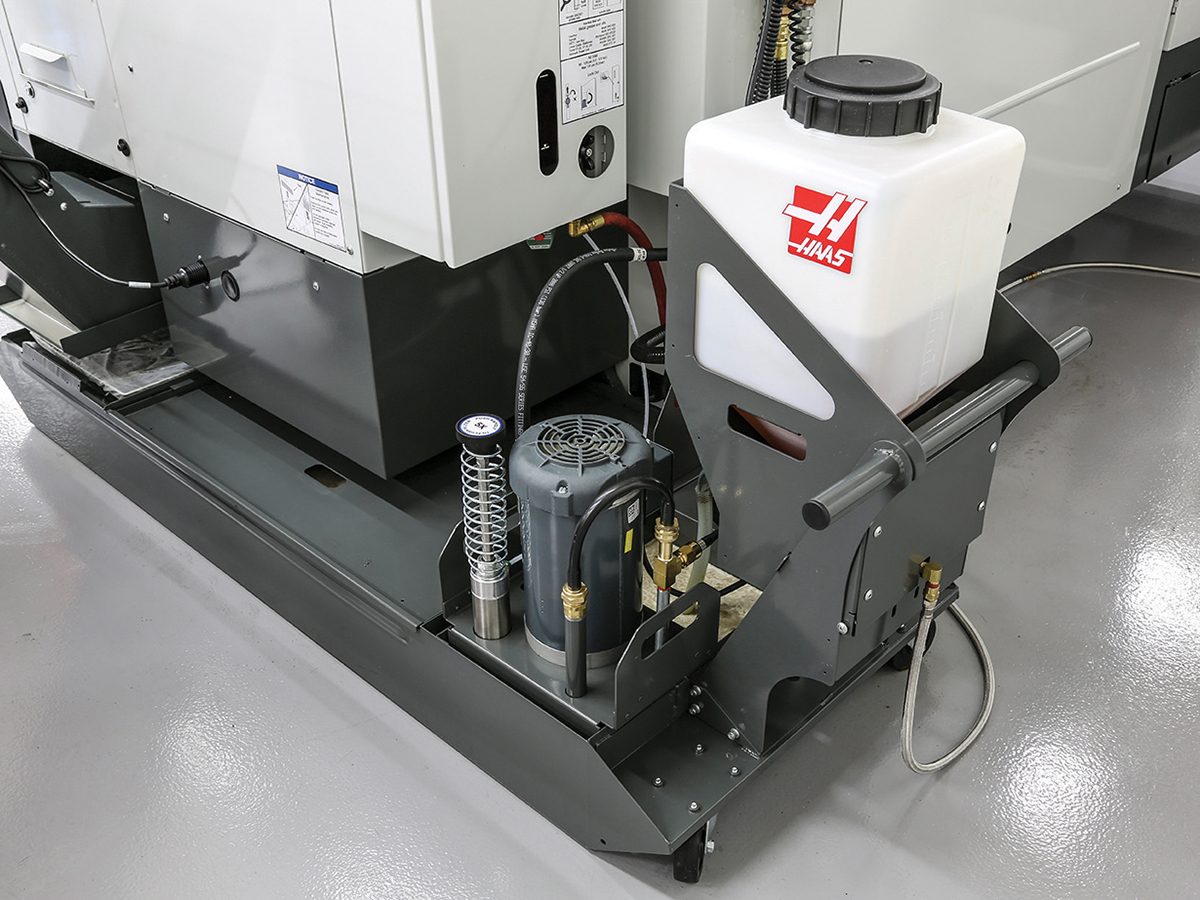
冷却液重新加注校准
有关如何安装和执行冷却液重新加注校准过程的指南,请参阅:
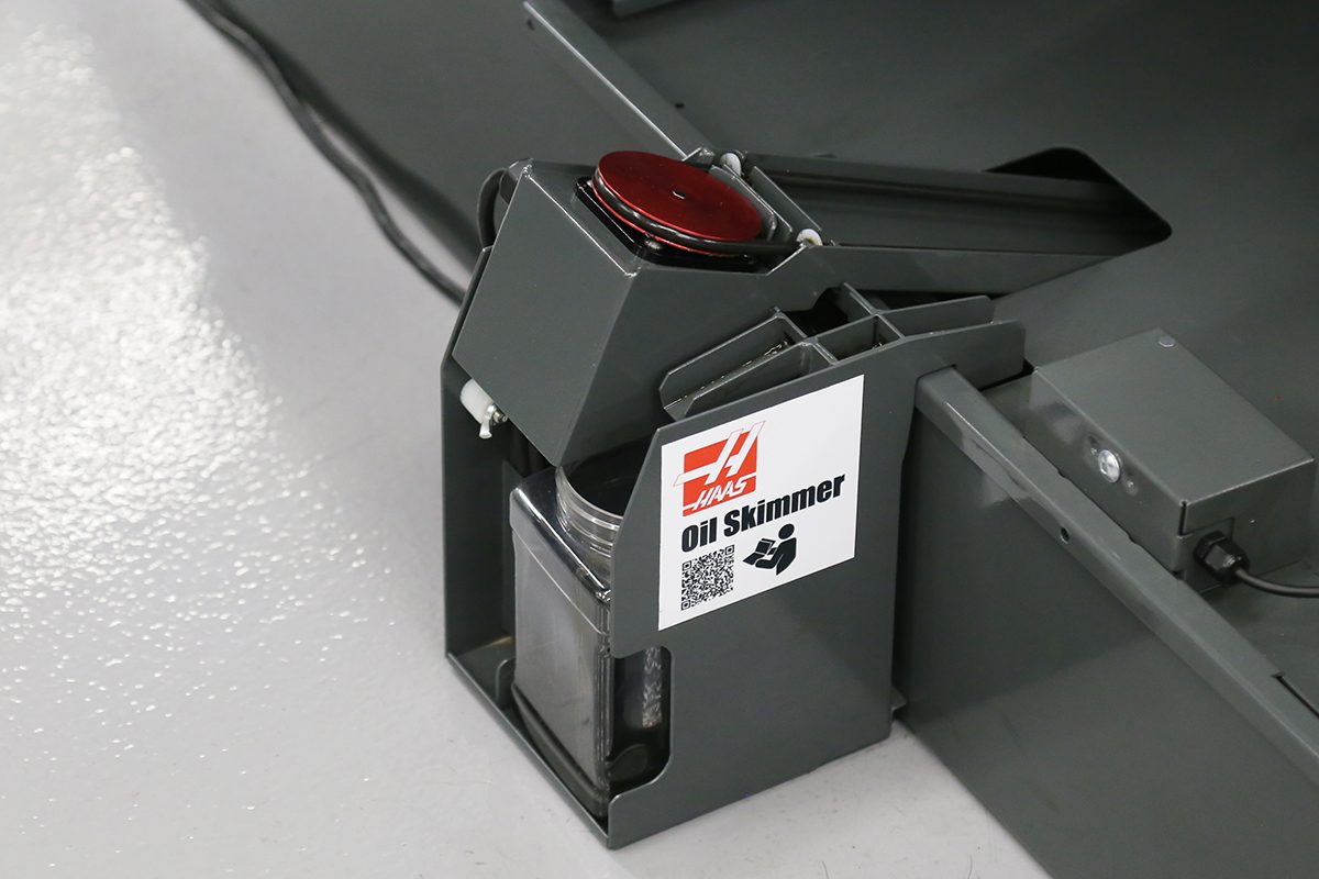
撇油器安装
有关如何执行撇油器安装过程的指南,请参阅:
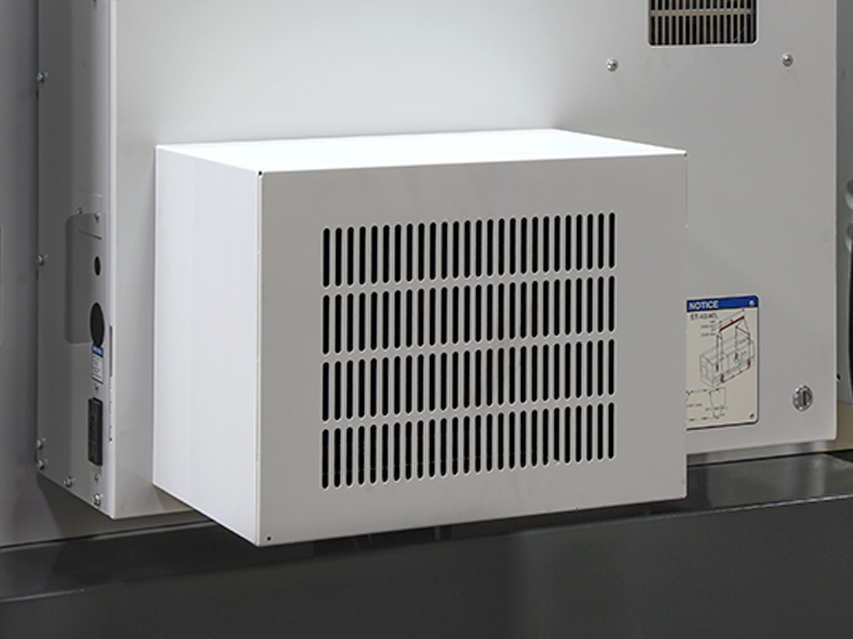
机柜冷却器安装
有关如何执行机柜冷却器安装过程的指南,请参阅:
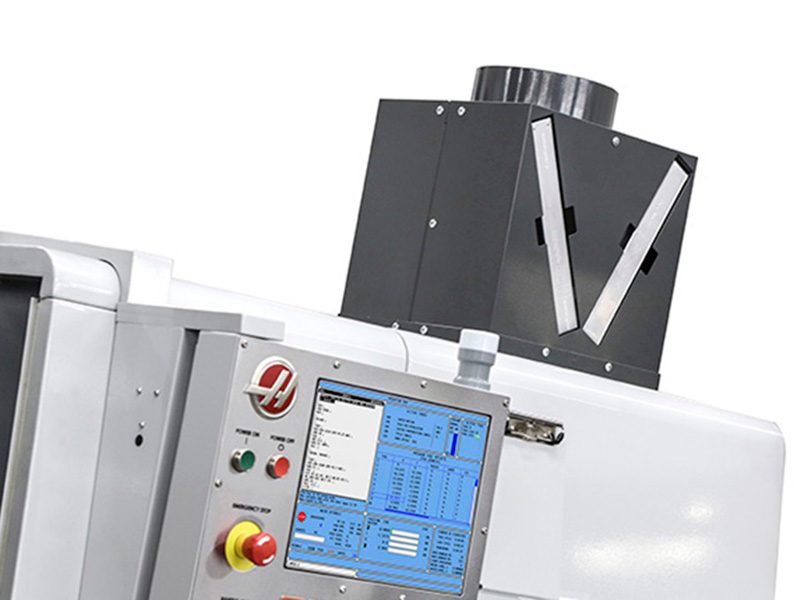
护罩排气安装
有关如何执行 护罩排气安装过程的指南,请参阅:
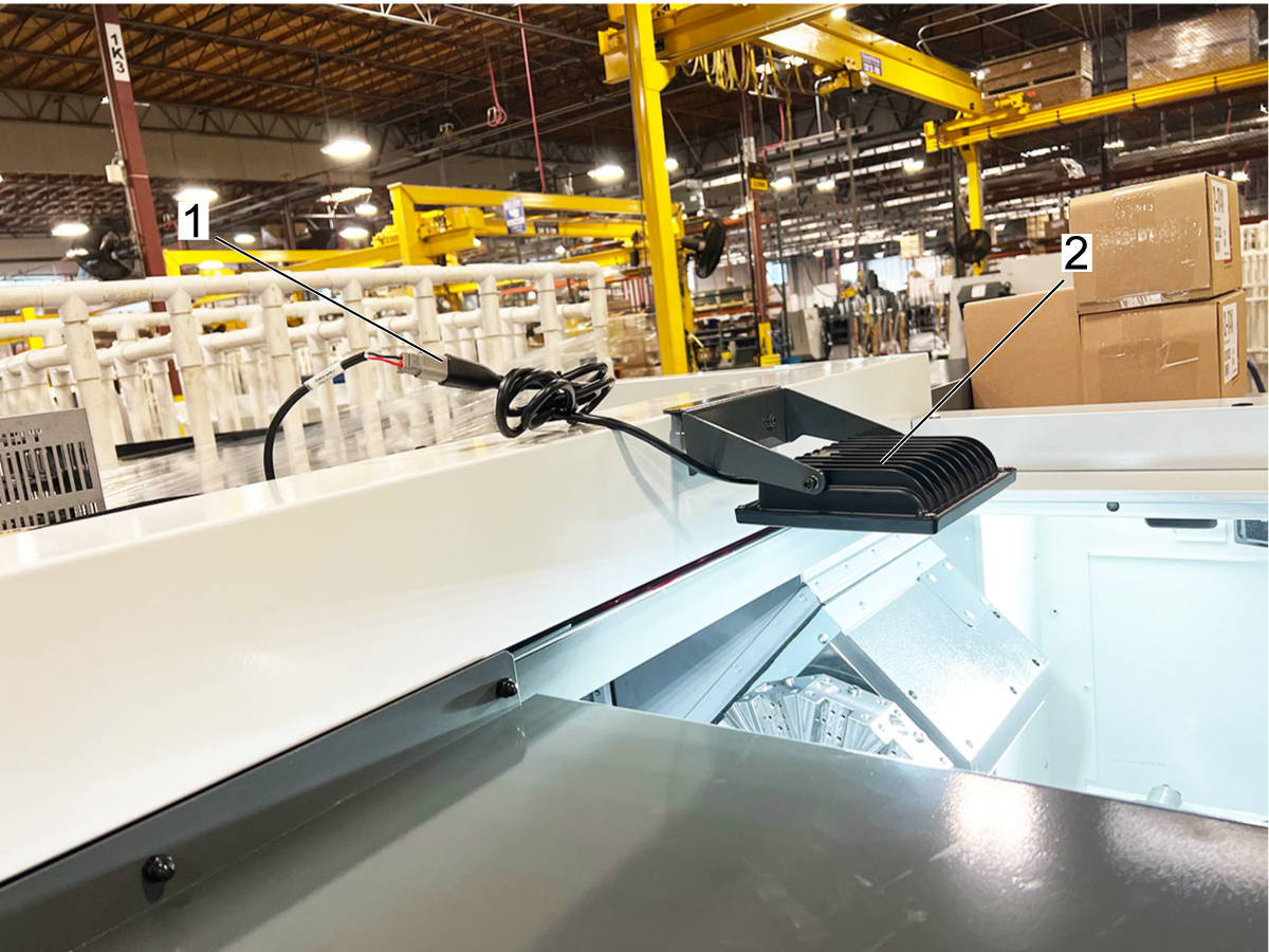
24V 磁性工作灯安装
有关如何执行磁性工作灯安装过程的指南,请参阅:
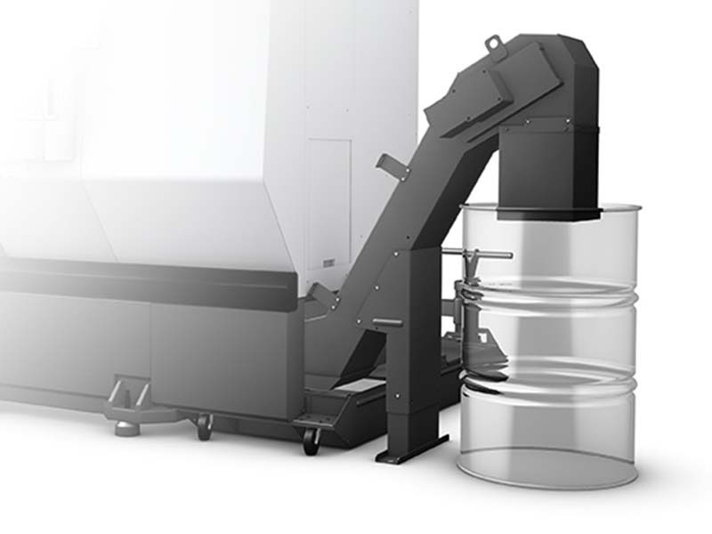
切屑输送机安装
有关如何执行切屑输送机安装过程的指南,请参阅:
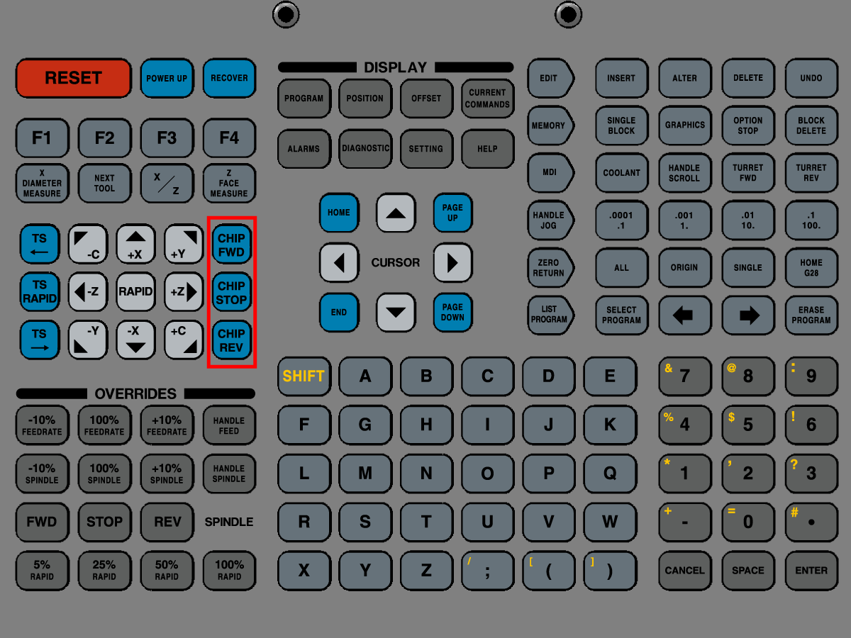
切屑输送机停止
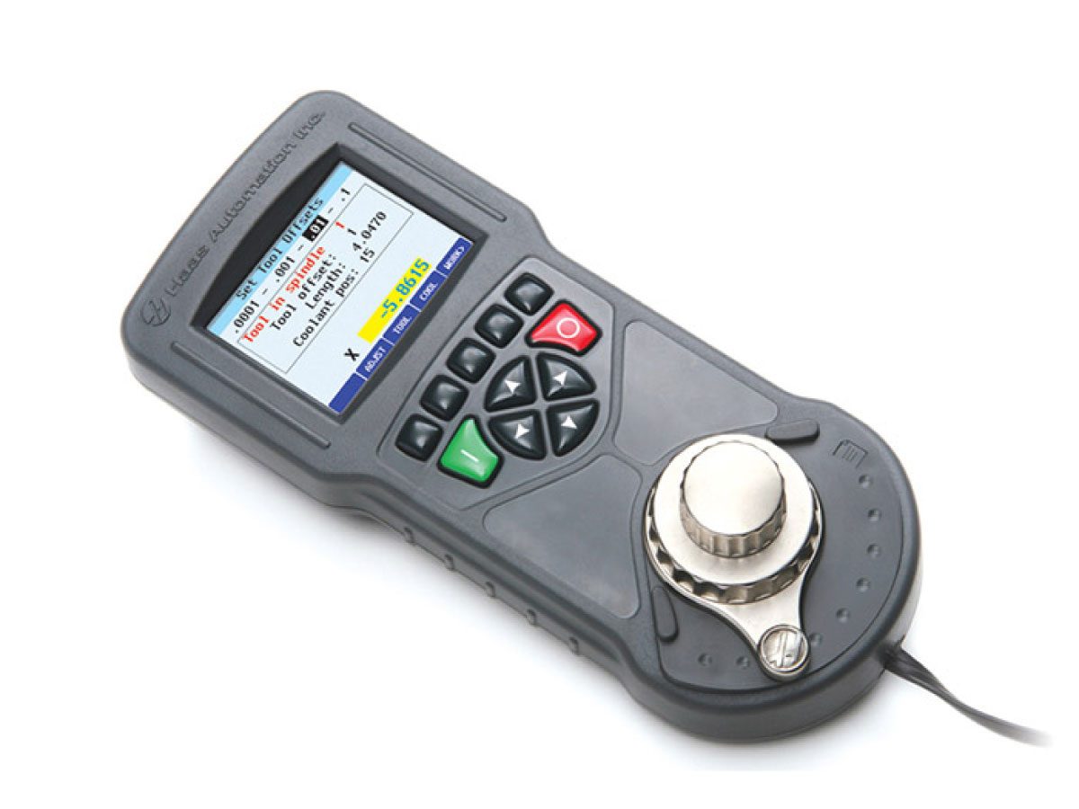
远程点动手柄颜色安装
有关如何执行远程点动手柄颜色安装过程的指南,请参阅:
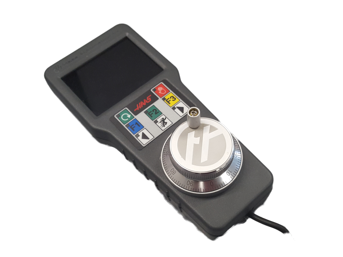
远程点动手柄触摸安装
有关如何执行远程点动手柄触摸安装过程的指南,请参阅:
.jpg)
测试门联锁
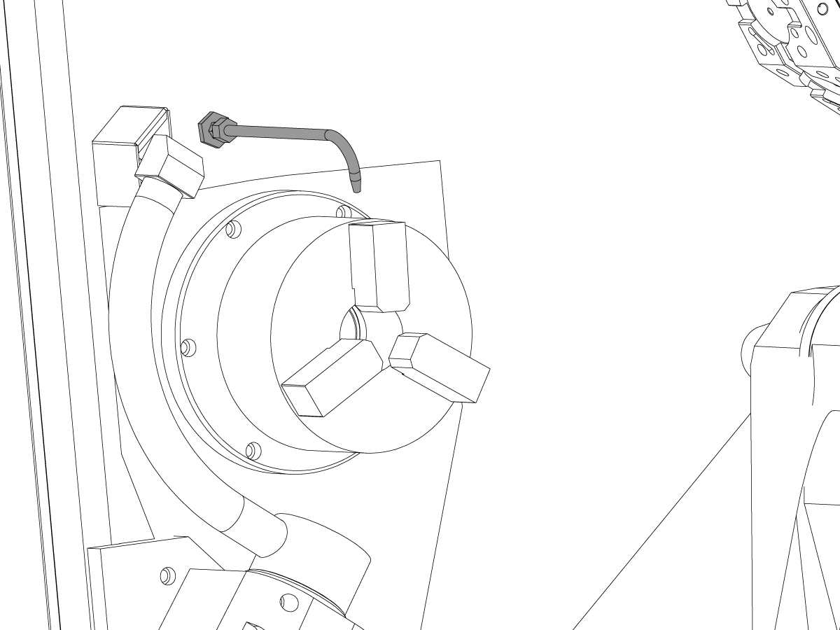
测试自动吹气 (AJB)
打开主空气阀。这向机器提供空气。
测试 AJB:
DS 机器:
有关这些 M 代码的详细信息,请参阅下面的车床操作员手册。
测试自动门选项
测试安全功能
自动工具预置仪 (ATP) - 校准
有关如何执行 ATP 校准过程的指南,请参阅:
测试零件捕获器 (PCAT)
如果机器包含 PCAT 选项,请执行测试过程。
注意:如果 PCAT 在返回时撞到门,请通知 Haas
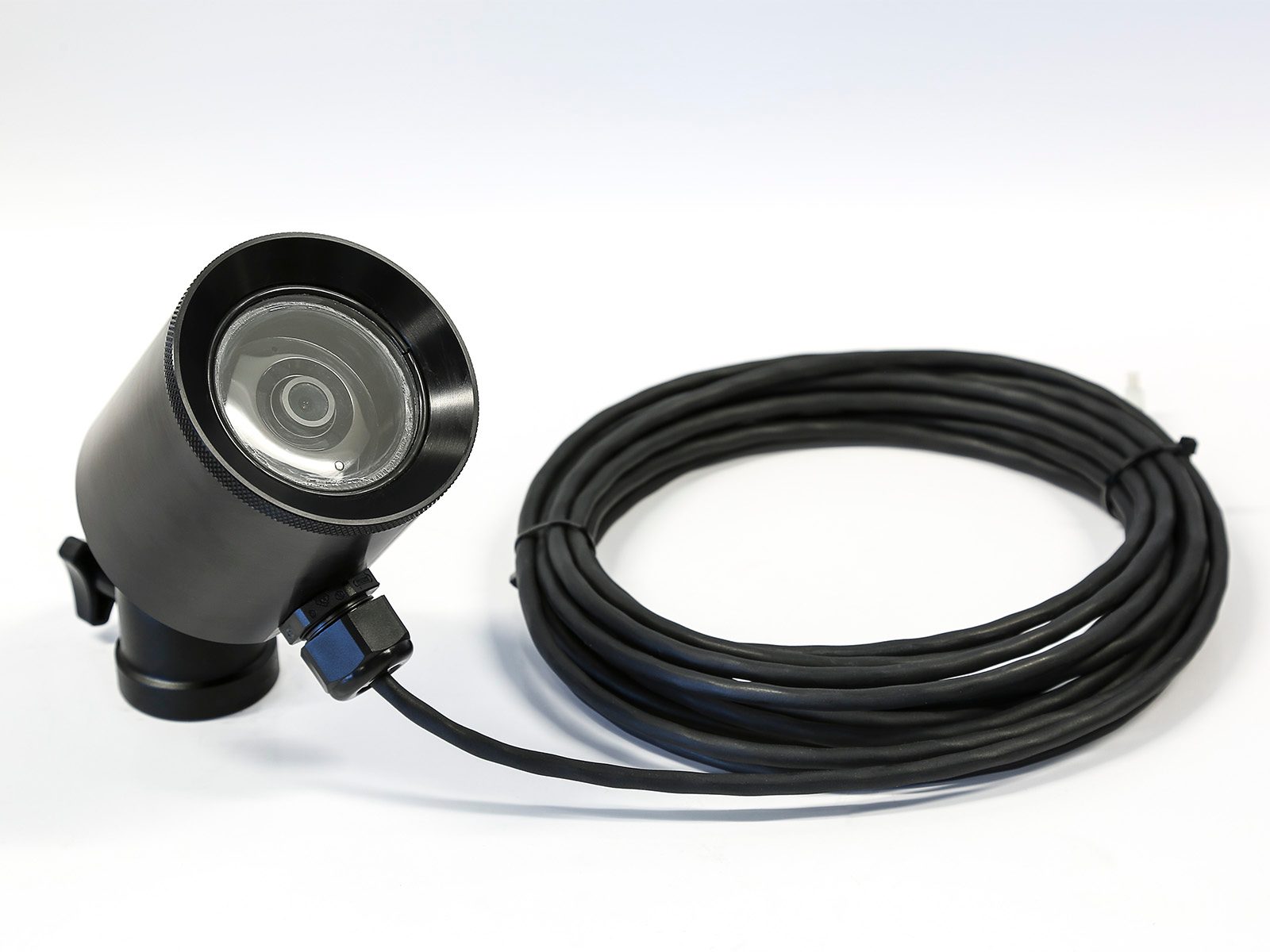
Wi-Fi 摄像机安装
有关如何执行 Wi-Fi 摄像机安装过程的指南,请参阅:
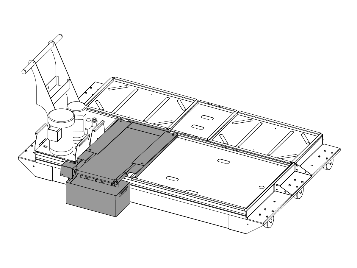
微型排屑器安装
有关如何执行微型排屑器安装过程的指南,请参阅:

测试 C 轴
测试 C 轴啮合:
测试 C 轴制动器:
使 Haas 机床保持以最佳性能运行,同时避免计划外停机。维护计划允许您管理您的日程安排,而不是陷入不合时宜的意外。有关建议的维护间隔时间,请参阅下面的链接。
AD0456
This procedure will show you how to install the Drop-In expansion style anchors to a Haas CNC.
NOTE: If the machine was built before Jan 2020 or is a VS or HDC series machine, please refer to the epoxy style anchoring procedure (AD0212) click here.
For instructions on how to anchor the various components for the Haas Cobot kits refer to the Haas Cobot - Anchoring instruction page.
This procedure applies to the following Service Kits:
| Mill | |
| Model | Part Number |
| DC-1 | 93-1001018 |
| DC-2 | 93-1001019 |
| DC-4 | 93-1001211 |
| DT/DM-1, DT/DM-2 | 93-1000601 |
| DT/DM-3 | 93-1001136 |
| EC-400/VC-400 | 93-1000567 See Note Below |
| EC-500/50 | 93-1001145 |
| EC-1600/UMC-1600H | 93-1000535 |
| EC-630 | 93-1000856 |
| GM-1 | 93-1001115 |
| GM-1XT | 93-1001235 |
| GM-2-3AX | 93-1000574 |
| GM-2-5AX | 93-1000542 |
| GR-510 | 93-1000574 |
| GR-712 | 93-1000574 |
| MM/SMM Reboot | 93-1001016 |
| UMC-350HD | 93-1000780 |
| UMC-400/SS | 93-1001224 |
| UMC-500/SS | 93-1000379 |
| UMC-750/SS (NON REBOOT) | 93-1000380 |
| UMC-750/SS (REBOOT) | 93-1001324 |
| UMC-1000/SS (REBOOT) | 93-1001324 |
| UMC-1250/SS | 93-1000644 |
| UMC-1500-DUO/SS-DUO | 93-1000871 |
| VF-1/2, VF-2TR, VF-2SS | 93-1000534 |
| VF-2YT, VF-2SSYT, VM-2 | 93-1000549 |
| VF-3/3SS, VF-4/4SS | 93-1000550 |
| VF-3YT/3YTSS, VF-3YT/50, VF-5/40, VF-5/40TR, VF-5/40XT, VF-5SS, VF-5/50, VF-5/50TR, VF-5/50XT, VM-3, VMT-750 | 93-1000548 |
| VF-6/40, VF-6SS, VF-6/40TR, VF-7/40, VF-6/50, VF-6/50TR, VF-7/50, VM-6 (Base with 8 leveling feet) Built between January 2020 and September 6th 2023 | 93-1000547 |
| VF-8/40, VF-9/40, VF-8/50, VF-9/50, VR-8, VR-9 (Base with 8 leveling feet) Built between January 2020 and October 6th 2023 | 93-1000546 |
| VF-10/40, VF-12/40, VF-10/50, VF-12/50 (Base with 8 leveling feet) | 93-1000545 |
| VF-11/40, VF-11/50, VR-11 (Base with 8 leveling feet) | 93-1000544 |
| VF-6/6TR/6SS/7/10/12 both 40T & 50T and VM-6 (Base with 6 leveling feet) Built September 7th 2023 and later | 93-1000999 |
| VF-8/9/11/14 both 40T & 50T and VR-8/9/11/14 (Base with 6 leveling feet) Built October 7th 2023 and later | 93-1001000 |
| VS-3 | 93-1000870 |
| Pallet Pool/RPL | |
| Model | Part Number |
| UMC-500PP | 93-3526 |
| UMC-750PP (V1) | See Note Below |
| UMC-750PP (V2) | 93-3527 |
| UMC-1000PP (V2) | 93-3527 |
| UMC-1250PP | See Note Below |
| EC-400PP | 93-3525 |
| VF-2YTPP | See Note Below |
| VF-4 PP | See Note Below |
| Robot Pallet Loader | See Note Below |
You would need to order individual parts, please contact your Local Haas Factory Outlet for availability.
| Lathe | |
| Model | Part Number |
| ST-10/10Y/15/15Y | 93-1000378 |
| ST-10L/10LY/15L/15LY | 93-1000855 |
| ST-20/25/20Y/25Y | 93-1000552 |
| ST-20L/20LY/25L/25LY/28L/28LY | 93-1001005 |
| ST-30/35/30Y/35Y, DS-30Y (REBOOT ONLY) | 93-1000541 |
| ST-30L/35L/LY | 93-1001079 |
| ST-40 | 93-1000540 |
| ST-40/40Y (Reboot) | 93-1000819 |
| ST-40L | 93-1000539 |
| ST-40L (Reboot) | 93-1000820 |
| ST-40S/45S/SY | 93-1001012 |
| ST-50/55 | 93-1000538 |
| TL-1 | 93-1000537 |
| TL-2 | 93-1000536 |
| Extended Liner System | |
| ST-10/10L/10Y/10LY | 93-1000844 |
| 93-1000845 | |
Tools required:
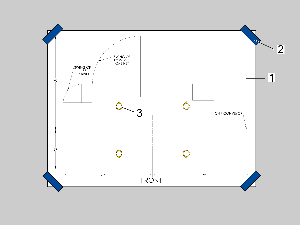
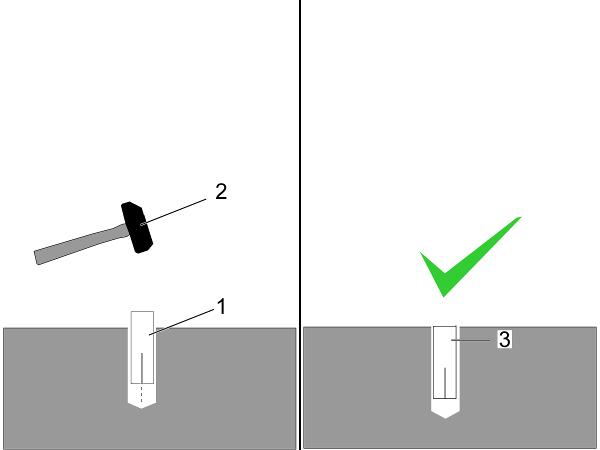
Use the provided SDS-Plus Style drill for the following steps:

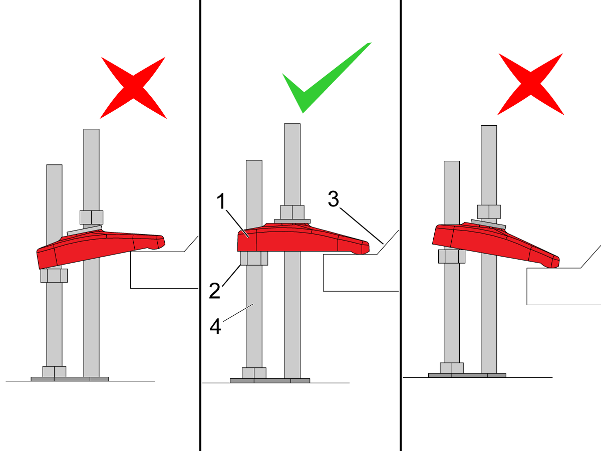
Make sure that the anchor strap [1] is level on the hex nut [2] and the machine base [3].
NOTE: Make sure the threaded stud [4] is perpendicular to the floor and not bent.
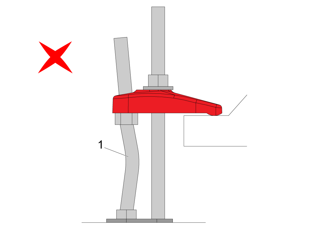
Make sure the threaded stud welded to the base is not bent as shown in the image [1].
If this occurs make sure that the anchor holes are drilled straight and re-drill them if necessary.
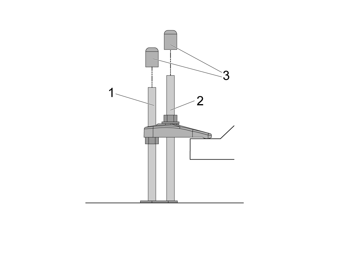
If there is clearance on the anchor [1] and stud [2] place the end caps [3] on the ends as shown in the image. Place these caps on all all anchors.
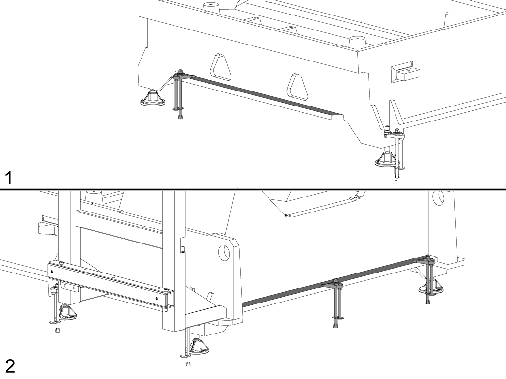
NOTE: The UMC-1250/SS does not have the anchoring fingers on the base foot. The indicated holes on the anchoring layout will have them anchoring down the base flange as shown in the image. Image [1] is the front of the machine, while image [2] is the back of the machine.
Recently Viewed Items
You Have No Recently Viewed Items Yet

此价格包含运费、出口和进口关税、保险费以及任何在运送至与您(买家)商定的位于法国的某一地点的过程中产生的其他费用。在 Haas 数控产品的交付中不会添加任何其他强制性费用。
随时掌握 HAAS 最新提示和技术……
HAAS TOOLING 接受以下条件:


This site is protected by reCAPTCHA and the Google Privacy Policy and Terms of Service apply.

2800 Sturgis Rd., Oxnard, CA 93030 / Toll Free: 800-331-6746
Phone: 805-278-1800 / Fax: 805-278-2255