My Haas Welcome,
!
Haas Tooling MyHaas/HaasConnect Sign In Register Haas Tooling MyHaas/HaasConnect Sign Out Welcome, My Machines Latest Activity My Quotes My Account My Users Sign Out
Find Your Distributor
  1. Select Language
    1. English
    2. Deutsch
    3. Español - ES
    4. Español - MX
    5. Français
    6. Italiano
    7. Português
    8. Český
    9. Dansk
    10. Nederlands
    11. Magyar
    12. Polski
    13. Svenska
    14. Türkçe
    15. 中文
    16. Suomi
    17. Norsk
    18. الإنجليزية
    19. български
    20. Hrvatski
    21. Ελληνικά
    22. Română
    23. Slovenský
    24. Slovenščina
    25. 한국어
    26. 日本語
    27. Українська
  • machines Main Menu
    • Vertical Mills
      Vertical Mills
      Vertical Mills View All
      • Vertical Mills
      • VF Series
      • Universal Machines
      • VR Series
      • VP-5 Prismatic
      • Pallet-Changing VMCs
      • Mini Mills
      • Mold Machines
      • High-Speed Drill Centers
      • Drill/Tap/ Mill Series
      • Toolroom Mills
      • Pocket Mill
      • Compact Mills
      • Gantry Series
      • SR Sheet Routers
      • Extra-Large VMC
      • Double-Column Mills
      • 3+2 Positioning Machines
    • Multi-Axis Solutions
      Multi-Axis Solutions
      Multi-Axis Solutions View All
      • Multi-Axis Solutions
      • Y-Axis Lathes
      • 5-Axis Mills
    • Lathes
      Lathes
      Lathes View All
      • Lathes
      • ST Series
      • Dual-Spindle
      • Box Way Series
      • Toolroom Lathes
      • Chucker Lathe
      • Pocket Lathe
      • Haas Bar Feeders
    • Horizontal Mills
      Horizontal Mills
      Horizontal Mills View All
      • Horizontal Mills
      • 50-Taper
      • 40-Taper
    • Rotaries & Indexers
      Rotaries & Indexers
      Rotaries & Indexers View All
      • Rotaries & Indexers
      • Rotary Tables
      • Indexers
      • 5-Axis Rotaries
      • Extra-Large Rotaries
    • Special Series
      Special Series
      Special Series View All
      • Special Series
      • EU_Series_Redirect
    • Automation Systems
      Automation Systems
      Automation Systems View All
      • Automation Systems
      • Mill Automation
      • Lathe Automation
      • Automatic Parts Loaders
      • Automation Models
    • Desktop Machines
      Desktop Machines
      Desktop Machines View All
      • Desktop Machines
      • Desktop Mill
      • Desktop Lathe
      • Control Simulator, Standard
      • Control Simulator, Premium
    • Shop Equipment
      Shop Equipment
      Shop Equipment View All
      • Shop Equipment
      • Knee Mill
      • Haas Manual Lathes
      • Haas Saws
    • Fabrication Machines
      Fabrication Machines
      Fabrication Machines View All
      • Fabrication Machines
      • Laser Cutting Machines
      • CNC Press Brakes
    • QUICK LINKS Special Series  Special Series 
      EU SERIES EU SERIES BUILD & PRICE | PRICE LIST BUILD & PRICE | PRICE LIST In-Stock Machines In-Stock Machines WHAT’S NEW WHAT’S NEW YOUR FIRST CNC YOUR FIRST CNC
      SHOPPING TOOLS
      • Build & Price a Haas
      • Price List
      • Available Inventory
      • CNCA Financing
      WANT TO TALK TO SOMEONE?

      A Haas Factory Outlet (HFO) can answer your questions, and walk you through your best options.

      CONTACT YOUR DISTRIBUTOR >
  • Options Main Menu
    • The Haas Control Value Option Packages
      Value Option Packages
      Value Option Packages View All
      • Value Option Packages
    • Product Image Spindles
      Spindles
      Spindles View All
      • Spindles
    • Product Image Tool Changers
      Tool Changers
      Tool Changers View All
      • Tool Changers
    • Product Image 4th- | 5th-Axis
      4th- | 5th-Axis
      4th- | 5th-Axis View All
      • 4th- | 5th-Axis
    • Product Image Turrets & Live Tooling
      Turrets & Live Tooling
      Turrets & Live Tooling View All
      • Turrets & Live Tooling
    • Product Image Probing
      Probing
      Probing View All
      • Probing
    • Haas Chip & Coolant Management Chip & Coolant Management
      Chip & Coolant Management
      Chip & Coolant Management View All
      • Chip & Coolant Management
    • The Haas Control The Haas Control
      The Haas Control
      The Haas Control View All
      • The Haas Control
    • Product Image Product Options
      Product Options
      Product Options View All
      • Product Options
    • Product Image Tooling & Fixturing
      Tooling & Fixturing
      Tooling & Fixturing View All
      • Tooling & Fixturing
    • Product Image Workholding
      Workholding
      Workholding View All
      • Workholding
    • Product Image 5-Axis Solutions
      5-Axis Solutions
      5-Axis Solutions View All
      • 5-Axis Solutions
      • 5 Easy Steps to 5-Axis
    • QUICK LINKS Special Series  Special Series 
      EU SERIES EU SERIES BUILD & PRICE | PRICE LIST BUILD & PRICE | PRICE LIST In-Stock Machines In-Stock Machines WHAT’S NEW WHAT’S NEW YOUR FIRST CNC YOUR FIRST CNC
      SHOPPING TOOLS
      • Build & Price a Haas
      • Price List
      • Available Inventory
      • CNCA Financing
      WANT TO TALK TO SOMEONE?

      A Haas Factory Outlet (HFO) can answer your questions, and walk you through your best options.

      CONTACT YOUR DISTRIBUTOR >
  • Why Haas Main Menu
      Discover the Haas Difference
    • Why Haas
    • MyHaas
    • Education Community
    • Industry 4.0
    • Haas Certification
    • Customer Testimonials
  • Service Main Menu
      Welcome to Haas Service
      SERVICE HOME Operator’s Manuals How-To Procedures Troubleshooting Guides Preventive Maintenance Haas Parts Haas Tooling Videos
  • Videos Main Menu
  • Main Menu
    • View All
    • View All
    • View All
    • View All
      • HTEC Curriculum Support
      • Haas Value Option Packages (VOP) Journey
    • View All
      • Haas 10 kg Cobot Package
      • Cobot Kits
      • DC-1 Drill Center
      • CNC Sales News
      • Do More With Your Haas
    • View All
    • View All
      • contact-us-test
      • 4 - AUTOMATION SYSTEMS
      • Carousel-V2
      • expert test
      • Demo_Day_Trident-test
      • Link Test
      • image-sale-tag-test
      • article-list-test
      • Haas 25 kg Robot Package
      • test-algolia-page
    • View All
    • View All
    • View All
    • View All
      • calc-test
    • View All
    • QUICK LINKS Special Series  Special Series 
      EU SERIES EU SERIES BUILD & PRICE | PRICE LIST BUILD & PRICE | PRICE LIST In-Stock Machines In-Stock Machines WHAT’S NEW WHAT’S NEW YOUR FIRST CNC YOUR FIRST CNC
      SHOPPING TOOLS
      • Build & Price a Haas
      • Price List
      • Available Inventory
      • CNCA Financing
      WANT TO TALK TO SOMEONE?

      A Haas Factory Outlet (HFO) can answer your questions, and walk you through your best options.

      CONTACT YOUR DISTRIBUTOR >
  • Haas Tooling Main Menu
  • Haas Service Parts Main Menu

My Haas Welcome,
!
Haas Tooling MyHaas/HaasConnect Sign In Register Haas Tooling MyHaas/HaasConnect Sign Out Welcome, My Machines Latest Activity My Quotes My Account My Users Sign Out
Find Your Distributor
  1. Select Language
    1. English
    2. Deutsch
    3. Español - ES
    4. Español - MX
    5. Français
    6. Italiano
    7. Português
    8. Český
    9. Dansk
    10. Nederlands
    11. Magyar
    12. Polski
    13. Svenska
    14. Türkçe
    15. 中文
    16. Suomi
    17. Norsk
    18. الإنجليزية
    19. български
    20. Hrvatski
    21. Ελληνικά
    22. Română
    23. Slovenský
    24. Slovenščina
    25. 한국어
    26. 日本語
    27. Українська
×

Search Results

Web Pages

Images

    • <
    • 1
    • >

RPL-30KG - UMC Installation - AD0951

Service Home How To Procedures RPL-30KG - UMC Installation - AD0951

RPL-30KG - UMC Installation - AD0951

- Jump to Section - Back to Top

3.2 RPL-30KG - UMC Installation

Recently Updated Last updated: 03/16/2026

RPL-30KG - UMC Installation


AD0951

Revision B - 04/2026

Introduction

The RPL-30KG is only compatible on machines with a 19-inch pendent. This is because the minimum software version that supports the RPL-30KG is 100.25.001.1301 which is only available for 19-inch monitor machines.

Note: For a list of options that are not compatible with the RPL, refer to the Specifications and Compatibility tab in the Introduction chapter.

This procedure shows how to install the RPL-30KG Dual Rack option on a UMC machine. The RPL option also requires the following options to be installed the machine:

  • Dual Switch Auto window Option 
  • Dual Zero Point Ready Kit
  • RPL-30KG Ready Kit
  • 100.25.001.1301 Software Version or later

This procedure is for the following kits:

  • 93-1001263 - RPL-30KG Install Kit UMC CE
  • 93-1001262 - RPL-30KG Install Kit Not CE
  • 93-1001268 - RPL-30KG Fence Field Install Kit

Note: Refer to Chapter 2 of this manual for instructions on installing the dual zero point ready on VMC and UMC machines.

In order to install an RPL-30KG to an existing machine, several different kits need to be ordered. The table below shows which field install kits need to be ordered depending on machine type.

Example: In order to field install an RPL-30KG on a UMC-750SS in Europe (CE required) you would have to order ALL of the following kits:

  • 93-1001310 - Dual Zero Point Ready Kit UMC-750
  • 93-1001270 - RPL-30KG Ready Kit UMC-750
  • 93-1001263 - RPL-30KG Install Kit-CE UMC
  • 93-1001268 - RPL-30KG Fence Kit
  • 93-1000941 - Dual Switch Autowindow Kit
  • 93-1000996 - Side Automation Safety Par Only
FIELD INSTALL KITS UMC-500 UMC-500 NEEDS CE
Dual Zero Point Ready Kit 93-1001311
RPL-30KG Ready Kit 93-1001269
RPL-30KG Install Kit 93-1001262 93-1001263 
RPL-30KG Fence Install Kit --- 93-1001268
Dual Switch Auto Window Kit 93-1000940
Side Automation Safety Parameter Kit 93-1000996
FIELD INSTALL KITS UMC-750 UMC-750 NEEDS CE
Dual Zero Point Ready Kit 93-1001310
RPL-30KG Ready Kit 93-1001270
RPL-30KG Install Kit 93-1001262 93-1001263 
RPL-30KG Fence Install Kit --- 93-1001268
Dual Switch Auto Window Kit 93-1000941  
Side Automation Safety Parameter Kit 93-1000996
FIELD INSTALL KITS UMC-1000 UMC-1000 NEEDS CE
Dual Zero Point Ready Kit 93-1001309
RPL-30KG Ready Kit 93-1001271
RPL-30KG Install Kit 93-1001262 93-1001263 
RPL-30KG Fence Install Kit --- 93-1001268
Dual Switch Auto Window Kit 93-1000941  
Side Automation Safety Parameter Kit 93-1000996

RPL Pallet Placement

1

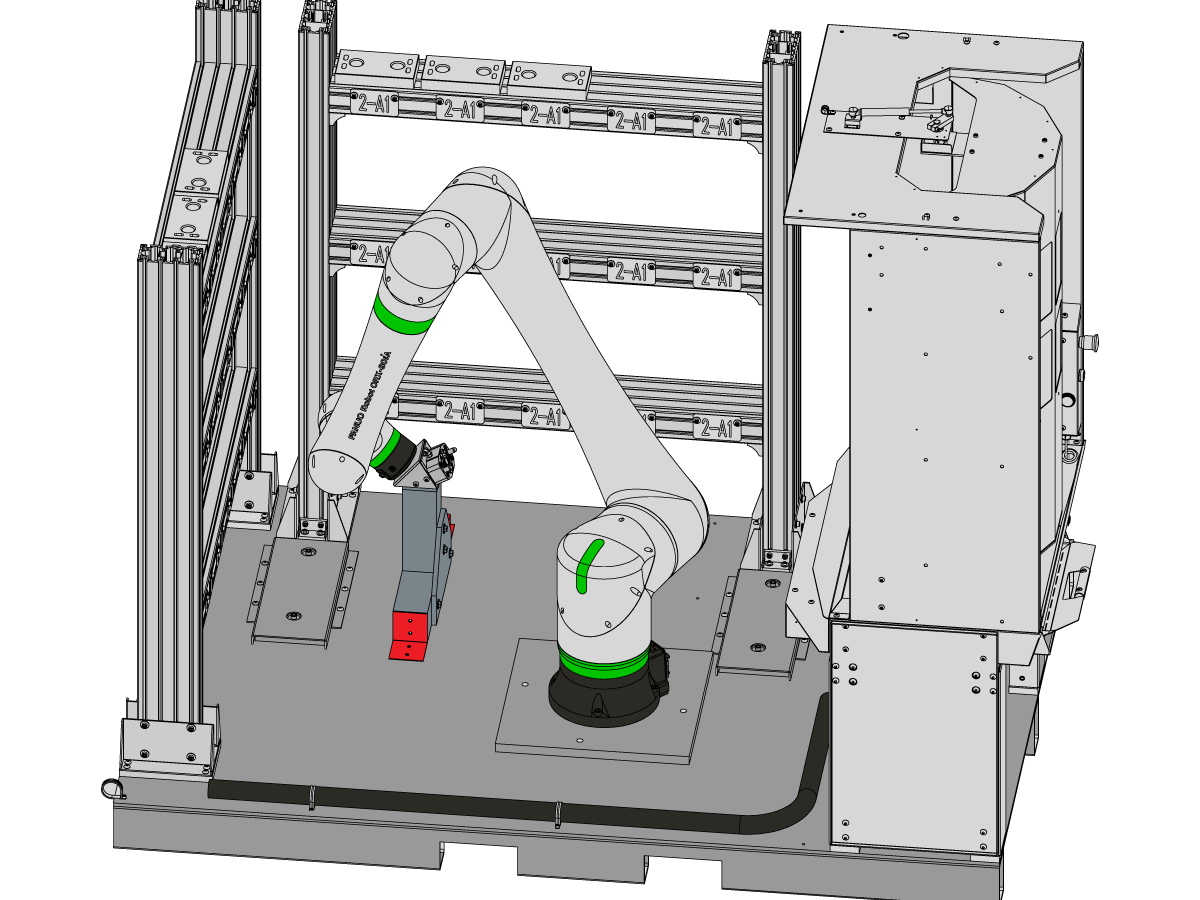
The RPL-30KG pallet comes in a shipping position as shown in the image.

The pallet will have the following components already installed:

  • Operator Load Station
  • Cobot 30KG
  • Cobot Control Box
  • Pallet Rack 1
  • Pallet Rack 2 (if applicable)

 Note: The 2nd pallet rack can be field installed if needed.

2

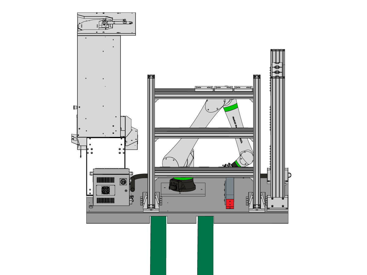
Lift the RPL-30KG pallet from the side using either a pallet jack or forklift.

Position the forks all the way through the pallet using the fork lift channels to move the pallet.

Continue to the next step to see where the pallet should be place based on the machine it is mating with.

3

The pallet needs to be positioned on the right side of the machine, located next to the auto window that is installed.

Place the pallet with the operator station facing the same direction as the front of the machine [1]. Make sure that the left edge of the pallet [5] is parallel to the right edge of the machine [4].

Position the pallet so that:

UMC-500:

  • The front side of the pallet [2] is [3] (20" or 50.8 cm) from the front of the machine [1]. 
  • The left side of the pallet [5] is [6] (7" or 17.78 cm) from the left side of the machine [4].

UMC-750:

  • The front side of the pallet [2] is [3] (17.5" or 44.45 cm) from the front of the machine [1]. 
  • The left side of the pallet [5] is [6] (7" or 17.78 cm) from the left side of the machine [4].

UMC-1000:

  • The front side of the pallet [2] is [3] (16" or 50.8 cm) from the front of the machine [1]. 
  • The left side of the pallet [5] is [6] (7" or 40.64 cm) from the left side of the machine [4].

4

Install the anchors [1] from the installation kit after the RPL has been placed in its final position. Use the provided template in the kit  to mark each individual anchor drilling location.

 Note: The kit comes with four anchors, but only three are required for installation [2]. The fourth anchor [3] is recommended but not required for anchoring down the RPL.

Follow the link below on how to install the anchors. 

Anchoring Instructions

5

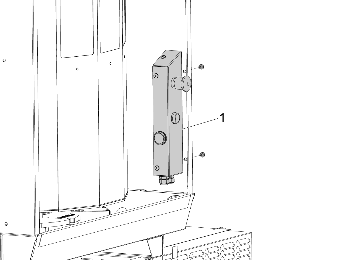
Cut the zip-tie to take the E-stop/work light button holder [1] off the load station. Rotate the holder [1] and use the bolts provided to mount the holder onto the load station. 

6

Install the work light lamps [1] on top of the load station. Use the BHCS [2] to fasten the work light mounts in position.

Connect the work light power cables to each end of the splitter cable [3]. 

Make sure that the splitter cable is also connected to the cable going to the worklights power supply in the electrical cabinet [4].

Extend 2nd Pallet Rack

Note: This section is only needed for RPL-30KG machines ordered with the second rack option.

1

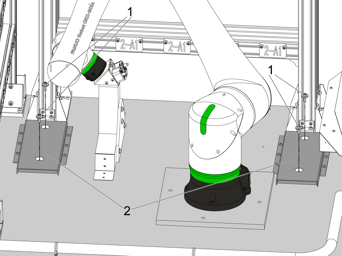
The 2nd rack needs to be moved out of it's shipping position at machine installation.

In order to move the rack, remove the 4 SCHS [1] that are holding the support legs to the base pallet.

The 4 screws and washers can be removed through the cutouts in the C-channel guides [2].

Once the screws are removed the rack can be pulled out. Refer to the rest of this section for more details.

Note: Keep the 4 SHCS and washers nearby since these will be reused to fix the support legs in their final location.

2

Once the support legs are free, slowly pull the rack out away from the robot as shown by the arrows.

 Warning: Do not pull the rack so far that the support legs are outside the C-channel guides. 

Use the leveling screws [1] and the leveling pucks [2] to support the rack as it is pulled away from the base.

Run down the leveling screws until there is light pressure on the pucks.

3

Reinstall the SHCS and washers to lock the rack support legs [2] in position. Use the same SHCS and washers that were removed in step 1 [1].

 Note: The fasteners do not go in the same location as they were removed from. Install 1 SHCS in the rear C-channel guide, and the hole closest to the rack at the edge of the base pallet [1].

Keep the bolts snug and adjust the pallet rack so that the washers and SHCS [4] are concentric with the C-channel guide cutout [3].

Once both sides have the washer centered in the cutout then torque down the 4 SHCS.

 Note: The washers do not need to be perfectly concentric. This is just to help ensure both support legs [2] are pulled out evenly. The cobot frame can be adjusted to match the physical orientation of the shelves.

4

Use a bubble level [1] to rough level the rack.

Place the level across the pallet holders on the top shelf of the rack.

Adjust the leveling screws [2] as needed until it bubble is in the center.

5

Take the bubble level and check if the posts of the rack are vertical.

Place the level flat against the post as shown in the image [1].

If the bubble is not in the center, adjust both leveling feet evenly so that the shelves are not moved out of level.

Once the bubble is in the center, tighten the locknut on the leveling screws to lock the rack in position.

 Note: The rack just needs to be rough leveled. The cobot frame can be adjusted to match the physical orientation of the shelves.

Electrical Installation

 DANGER: Working with the electrical services required for CNC machines is extremely hazardous and can result in serious injury or death.

Before connecting line wires to the CNC:

  • Turn off all power to the machine at the source.
  • Perform a Lockout-Tagout (LOTO) procedure to ensure the power remains off during service.
  • Verify that power has been disconnected by using an AC voltage detector on all incoming lines.

If you are uncertain about how to safely disconnect power or perform LOTO procedures:

  • Do not proceed.
  • Contact qualified personnel or obtain appropriate assistance before continuing.

Failure to follow these precautions may result in electrical shock, equipment damage, or fatal injury.

 Danger: Before beginning any work inside the control cabinet, verify that the High Voltage indicator light on the 320V Power Supply / Vector Drive has been off for a minimum of five (5) minutes. This waiting period ensures that residual voltage has dissipated and reduces the risk of electric shock.

Certain service procedures involve high-risk electrical components and may pose serious injury or fatality hazards. Technicians must not attempt any procedure unless they have a complete understanding of the steps involved and the associated risks.

If there is any uncertainty regarding a procedure, contact your Haas Factory Outlet (HFO) to arrange for a qualified service technician.

1

Perform the following steps to connect the cobot to the Haas machine.

Main Transformer

  • Connect cable [1] P/N 33-8570 to Main Transformer follow the labels to terminals 77 and 78,  connect the ground loop terminal to chassis.

I/O PCB and Maincon PCB

Cable P/N 33-8561C has multiple connections:

  • Connect the E-STOP terminal block connections  to SIO PCB TB-1B (see diagram) [2].
  • Verify the jumper is installed on the SIO PCB at JP1
  • Connect the Setup mode terminal block connections to SIO PCB TB-3B (see diagram) [2].
  • Connect the cable labeled P1 SIO to the SIO PCB at P1 [3].
  • Connect the RJ-45 cable [4] to Ethernet to USB adapter [5] (P/N 33-0636).  Connect the USB connector end to the Maincon PCB J8 top port (see diagram). Add a ferrite filter 64-1252 to the USB adapter.
  • Mount the 24VDC Power Supply [11] to the left side of the control cabinet and plug into connector labeled 24V PS on cable 33-8561C. Connect cable 33-1910A [10] to the 24VDC Power Supply [11] and plug into P3 on the PSUP PCB.
  • Plug the User Relays into K9 and K10. (see diagram) [12].

Note: If the machine does not have a Regen Vector Drive, do not plug anything into the connector FILTER OV FAULT.

Robot Electrical Box to Robot Control

  • Connect the Robot Control Signal Cables [7] P/N 33-1542 to the Robot Electrical Interface Box. Add a ferrite filter 64-1252 to the RJ-45 cable. See the next step for more detail on where to connect the signal cable inside the Robot Control Box.

IMPORTANT: When connecting the Robot Control Signal Cable [7], make sure to line up the M12 connector female notch with the M12 connector male key to prevent any misalignment that could result in damaged pins. 

Robot Power

  • Connect the 220VAC power cable [8] 33-1552 to the Robot Electrical Interface Box. Connect the other end to the Robot Control Box [6].

Robot Safety Device 

  • Connect the light curtain receiver cable [9] from the electrical interface box to the light curtain receiver. 
  • Connect the light curtain emitter to the Robot Interface Box using the emitter cable [13].

2

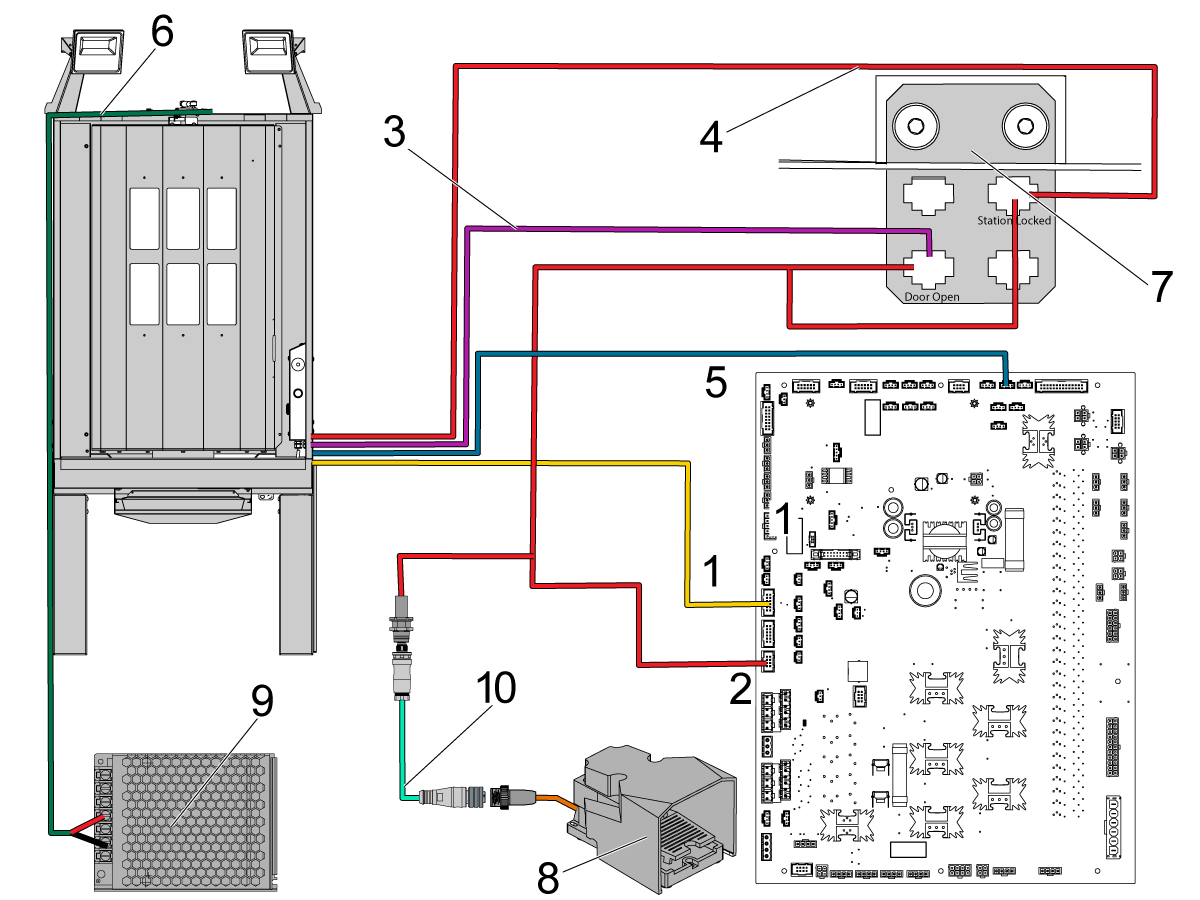
The cables coming from the load station are connected to the bracket in the previous step [7], or routed all the way to the control cabinet. Make sure the following cables are connected:

  1. 33-2565 - Connect to P12 on IOPCB 
  2. 32-1303 - This is connected to P14 on the IOPCB. One end connects to the cable bracket at the Door Open label and the Station Locked label. The other end is connected to the cutout at the skirt of the machine where the foot pedal connects. If there is already a cable routed to this connector it needs to be replaced with the 32-1303 cable.
  3. 32-1286 - Connects to the foot pedal assembly [8] and then also to the connector of the cable 32-1303.
  4. 32-1304 - Connect to the cable bracket at the Door Open label
  5. 33-1308 - Connect to the cable bracket at the Station Locked label
  6. 33-1482 - Connect to P50 on the IOPCB (pallet alarm). 
  7. 33-5838 - Connect work lights to splitter on top of load station. And then connect to work light power supply [9].

Note: The foot pedal assembly [8], cable 32-1286 [10] and the 32-1303 [2] cables are found in the Zero Point Installation kits.

3

 Warning: If the Haas Machine is powered ON, disconnect the 220VAC power cable from the electrical interface box. 

Place the electrical interface box on the enclosure of the Haas Machine.

Feed the other end of the robot signal cable 33-1542 coming from the front of the interface box and the gripper solenoid cable 33-1548 through the right side of the cobot control box [1].

Open the control box and connect the RJ-45 cable to port CD38A [2] located in the upper right corner of the PCB on the back wall of the control box.

Pull enough slack of the robot signal and gripper solenoid cable so that they can be connected to the IO/Safety PCB [3] located on the inside of the control box door.

See the next step for where to connect the robot signal and gripper cable to the IO/Safety PCB.

4

Move the cobot control box [1] off of the RPL pallet and place it next to the electrical cabinet of the Haas machine. 

Once everything is connected inside the control box, connect the 220VAC power cable coming from the interface box 33-1552 on the Haas machine. Place the interface box [3] on the side of the electrical cabinet.

The power cable is connected to the 4 pin connector on the right side of the control box [1].

 Note: The connector is keyed. Make sure you have the connector oriented correctly before trying to connect to the control box. 

Secure the connector by tightening the threaded collar [2].

5

Connect the teach pendent tablet to the control box.

Connect the male end of the teach pendent cable [1] to the control box terminal on the right side.

Connect the other end of the teach pendent cable to the teach pendent holster [2].

6

 IMPORTANT: The RPL-30KG should already have the connections made inside the cobot control box.  Refer to the below steps as a reference in case any connections have come loose.

Verify that all the connections in steps 7-11 in this section have been made correctly.

7

The cobot control box will come with jumpers on the safety/IO PCB. These jumpers will have to be moved in order to connect the robot signal cable to the safety/IO PCB.

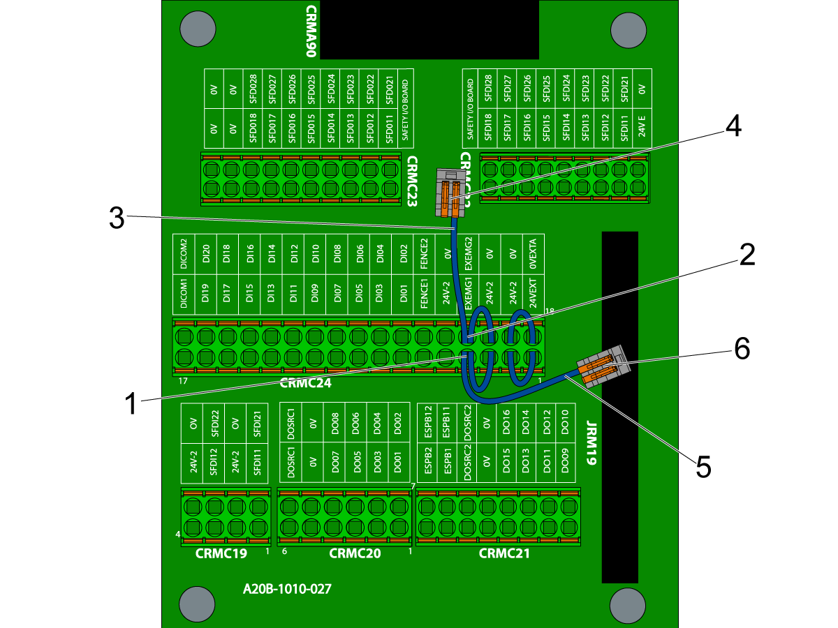
The jumpers will be connecting the following pins on CRMC24:

  • 24VEXT to 24V-2 (p1 to p2) [1]
  • 0VEXTA to 0V (p18 to p19) [2]
  • EXEMG1 to 24V-2 to FENCE1 (p4 to p5 to p6) [3]
  • EXEMG2 to 0V to FENCE2 (p21 to p22 to p23) [4]

 Note: All terminal locations are labeled on the PCB as shown in the image.

8

Disconnect the jumper from {EXEMG1 to 24V-2 to FENCE1} and the jumper from {EXEMG1 to 24V-2 to FENCE1}.

Move the jumpers so that they are connected in the following way on the CRMC24 terminal:

  • 24V-2 to EXEMG1 and leave FENCE1 disconnected (p3 to p4 and FENCE1 disconnected) [1]
  • 0V to EXEMG2 and leave FENCE2 disconnected (p20 to p21 and FENCE2 disconnected) [2]

Use the wago connectors provided in the integration kit. Connect the FENCE2 pin of the jumper [3] to one wago connector [4]. Then connect the FENCE1 pin of the jumper [5] to the other wago connector [6].

9

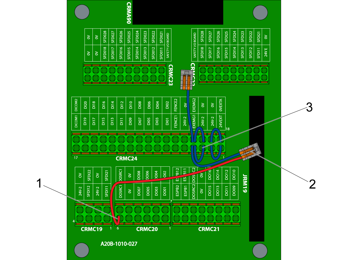
Connect the red jumper wire 33-1553 to the safety/IO PCB.

Connect one end of the red jumper wire to the DOSRC1 (p6) [1] on CRMC20.

Connect the other end of the red jumper wire to the wago connector [2]. Use the wago connector that is connected to the blue wire labeled FENCE1.

Note: The label on 33-1553 is labeled pin 3. Use the wago connector since the other end of the blue FENCE1 wire is connected to pin 3 [3].

10

Route the robot signal cable to the safety/IO PCB. Connect the cable to the safety/IO PCB as shown in the image:

Connections to CRMC24

  • GREEN wire to 24V-2 (p5)
  • GREY wire to FENCE1 (p6)
  • BROWN wire to 0V (p22)
  • RED wire to FENCE2 (p23)

Connections to CRMC19

  • VIOLET wire to SFDI11 (p1)
  • BLACK wire to 24V-2 (p2)
  • YELLOW wire to SFDI12 (p3)
  • WHITE wire to 24V-2 (p4)
  • BLUE/RED wire to SFDI21 (p5)
  • BLUE wire to 0V (p6)
  • PINK wire to SFDI22 (p7)
  • GREY/PINK wire to 0V (p8)

11

Route the dual gripper solenoid power cable 33-1548 [1] to the safety/IO PCB. Make the following connections:

Connections to CRMC20

  • BLACK to DO01 (p1)
  • RED to DO03 (p2)
  • WHITE/BLACK & WHITE/ORANGE to 0V (p5)
  • ORANGE to DO02 (p7)
  • BROWN to DO04 (P8)
  • WHITE/BROWN & WHITE/RED to 0V (p11)

12

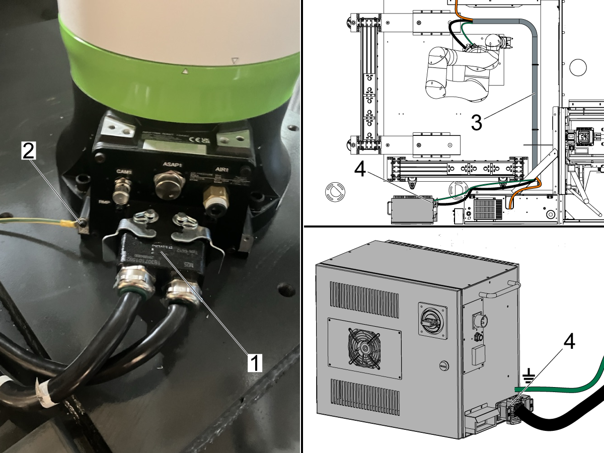
Make sure that the connector going to the base of the cobot is secured [1] as well as the ground wire [2]. Make sure that the connector on the control box side [4] is also secure.

Route the cobot power cable and grounding cable through the conduit [3] along with the other cables going to the load station.

Install Light Curtains

1

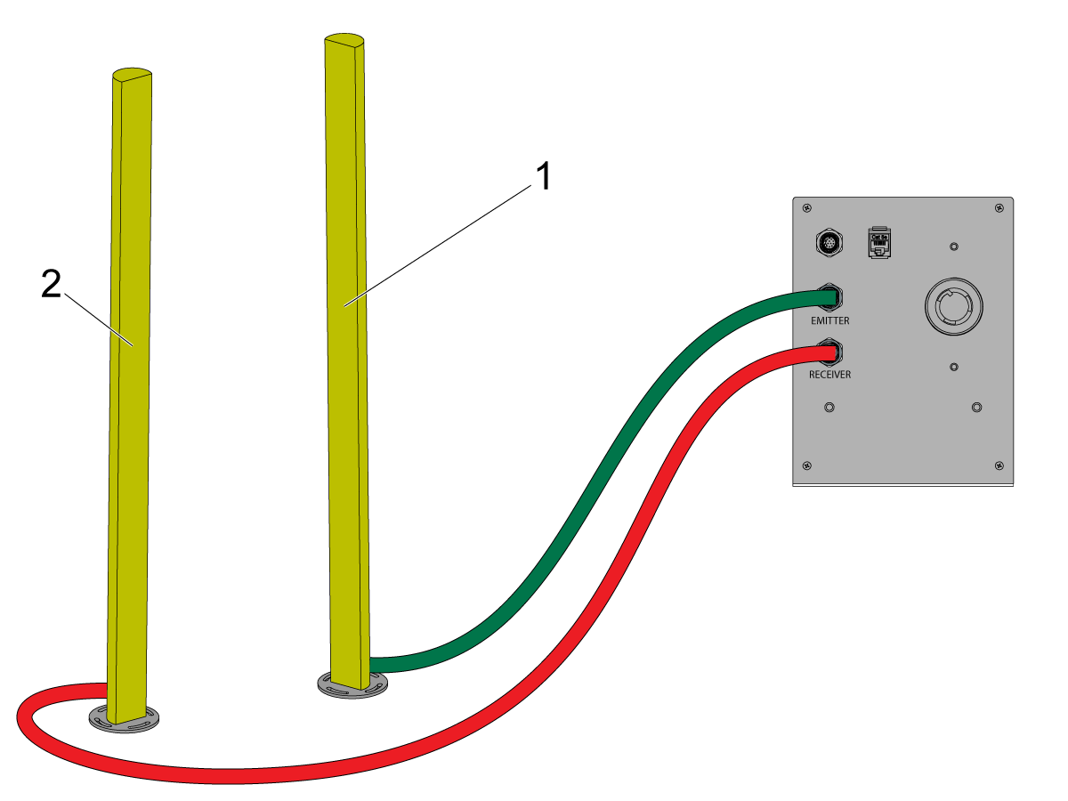
Place the light curtains in position  as shown in the image.

Place the emitter post [1] in between the back of rack 1 and the electrical control cabinet.

Use the 2 mirror posts [2] to redirect the beam to the Receiver post [3] which is placed next to the operator load station door.

 Note: If the RPL-30KG came with a safety fence instead of a light curtain assembly, refer to the safety fence installation section.

2

After the light curtains and mirrors are in position, make sure all the cables are connected.

Connect the emitter light curtain [1] to the emitter terminal on the interface box.

Connect the receiver light curtain [2] to the receiver terminal on the interface box.

 Note: Route the light curtain emitter cable underneath the RPL base pallet.

Lube Panel and Air Booster - Installation

1

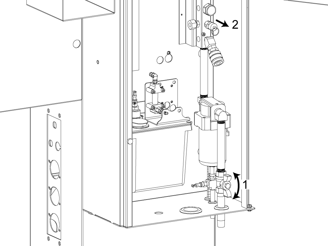
Close the air valve [1] at the bottom of the lube cabinet.

Bleed the remaining air out of the manifold by pulling on the air release [2]. Make sure the gauge on the manifold reads zero.

2

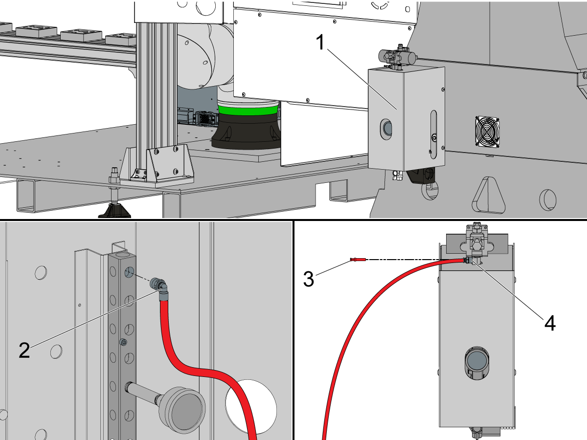
Install the elbow fitting [1] directly into the air manifold on the front face as shown in the image. 

Install the FITG COMP 3/8 X 1/4 MNPT BR STR [2] onto the manifold. This will allow you to then install the SOLENOID ASSY LS/AIR BLAST ZERO POINT [3]. 

Note: The solenoid will be plugged in during the Hose and Cable Routing section of this procedure.

3

Connect the red hose to the push connect fitting [2] that was just installed in the air manifold in the lube cabinet.

Route the hose out the bottom of the lube cabinet and route it to the top of the air booster assembly [1].

Remove the plug [3] from the push connect and connect the hose to the push connect fitting [4].

4

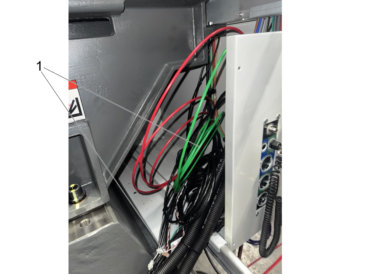
Remove the back panels to access the zero point hoses and cables that are coiled in the back of the machine.

These hoses and cables will go to the air booster assembly which is placed on the back of the machine.

Run the hoses underneath the enclosure. The hoses and cables that need to be routed to the air booster assembly are:

  • Red Hose - Zero Point Clamped airline
  • Green Hose - Zero Point Unclamped airline
  • 33-1307 - Pallet Clamped pressure sensor
  • 33-1306 - Zero Point Unclamp solenoid power cable

Note: These cables are included in the zero point ready kit. Refer to the zero point installation section in chapter 2 for more details.

5

Install the Air Booster on the back of the machine using the magnets to attach it.

6

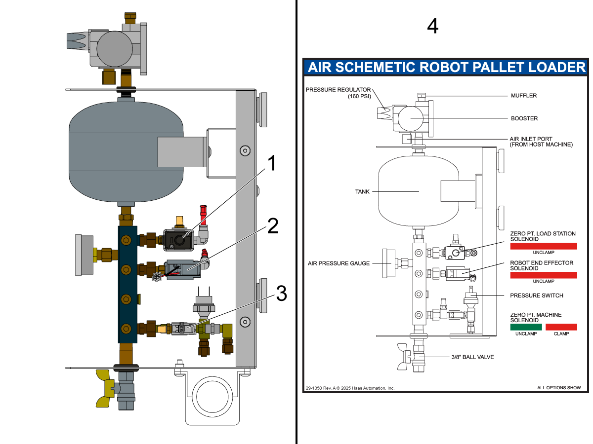
The air booster assembly includes solenoids for the following components:

  • Zero Point Load Station Solenoid - Unclamp [1]
  • Robot End Effector Solenoid - Unclamp [2]
  • Zero Point Machine Solenoid - Unlcamp [3]

Note: Refer to the decal [4] on the air booster for a more in depth breakdown of the components on the assembly.

7

Connect the green hose to the unclamp port [1] of the solenoid denoted with a green zip tie on it.

Connect the red hose to the clamp port [2] of the solenoid denoted with a red zip tie on it.

8

Connect the air hose to the 90 degree push connect underneath the receiver of the load station [1].

Route the airline through the conduit and connect it to the load station solenoid [2] located inside air booster assembly.

9

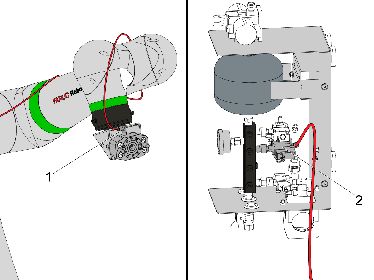
Connect the air hose to the 90 degree push connect on top of the zero point gripper on the robot [1].

Route the airline along the robot arm through the conduit and connect it to the robot gripper solenoid [2] located inside air booster assembly.

Note: Route the air hose through the conduit when connecting the hose to the push connect on the gripper.

10

Connect cable 33-1307 CBL AIR VISE PRESS SWS PP ROBOT21FT to the pressure sensor as shown. 

Route the cable back to the I/O board and plug this into P13 using the adapter cable provided in the kit.

 Note: The pressure sensor should be on the fitting where the red hose is connected. This sensor makes sure the zero point is clamped.

11

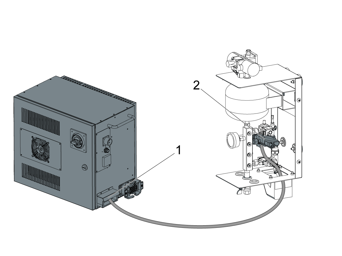
Connect cable 33-1306 to P36 [5] on the IO PCB. Connect the coolant refill to the pigtail if needed.

Route the other end directly to the Air Booster.

Connect the V-1 end [1] to the solenoid going to the zero point in the machine [4].

Connect the V-2 end [2] to the solenoid going to the load station zero point [3].

12

Connect the cobot gripper solenoid power cable 33-1548 from the cobot control box [1] to the air booster assembly

Route the cable into the air booster and connect it to the gripper solenoid [2].

Once the gripper cable is connected, double check that all hoses and cables are connected to the solenoids. Then reinstall the sheet metal cover on the air booster assembly.

First Power Up

1

Power ON the Haas Machine. Once the machine is booted up, turn the main breaker on the cobot control box [1] to the ON position.

Power on the teach pendent tablet by pressing the button on the side [2] as shown in the image.

Once the teach pendent powers on, swipe up from the bottom to unlock the tablet and get to the home page as shown in the image [3].

2

Swipe up to view the list of apps installed on the teach pendent.

Press on the Tablet TP app icon [1] to open the teach pendent application.

If the control box was just powered on then you will see the loading screen [2] indicating that the control box is still booting up. 

Note: It may take a 1-2 minutes for the control box to fully boot up.

3

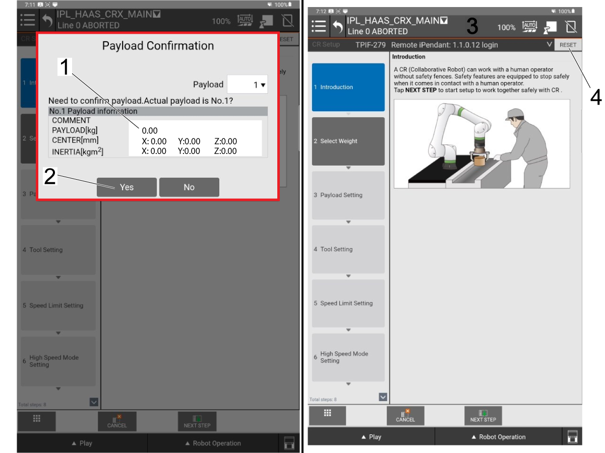
Once the application boots up there will be a Payload Confirmation window that pops up.

The cobot will list the payload, center of mass, and inertia that is detected. Since the cobot is not yet connected to the Haas machine and there is no grippers installed, there should be no payload detected.

Note: Small deviations in payload on the payload confirmation pop up will not impact the cobot. If you notice a difference in payload on this screen still continue.

Check that the listed payload seems accurate and then press [Yes] [2] to continue.

Once the payload confirmation is successful you will be taken to the main menu. If there are any alarms present they will show up near the top of the screen [3]

Press [Reset] [4] to clear any alarms. If not all alarms clear, make sure the Haas machine is booted up and not E-stopped.

4

Turn on the Haas CNC.

Zero Return all Axes.

Insert Service USB key.  Go into Service mode.

Go to Parameters> Factory tab.  Change the following:

  • 1278 [1278:] Robot Ready E-Stop Enabled to TRUE
  • 2191 [694:] LIGHT CUTAIN TYPE to LC_TYPE_1
  • 2192 [:] Light Curtain Trigger Threshold to 0

Verify that the following  parameters are set to these values:

  • 2128 [:] PALLET POOL TYPE to 4 Robot
  • 2129 [:] PALLET LOADING SHELF to PP_SHELF_A

Go to Settings and change the following:

  • 382 Disable Pallet Changer to None
  • 372 Parts Loader Type to None
  • 376 Light Curtain Enabled to On

5

Press [CURRENT COMMANDS] and navigate to the Devices -> Robot -> Setup menu.

Press [E-STOP] on the Haas pendent.

Then press [F1] [1] to establish a connection to the cobot.

Wait for a few seconds for the Haas machine to connect to the cobot.

Note: If this is the first time the Haas machine has connected to the cobot you will see the Activation popup on the Haas pendent.

If the cobot already has been activated, then you will know that you are connected based off the robot icon on the lower right corner of the Haas icon. A green icon indicates a connection. A red icon indicates the cobot isn't currently connected [2].

6

If you need to activate the cobot, then you will get the popup similar to the image.

The popup will have the following displayed:

  1. Software Version of the Haas Machine
  2. MAC Address of the cobot connected [1]
  3. Generated Code

You will need to locate and enter the following to successfully activate the cobot:

  1. F Number [2]
  2. Unlock Code [3]

Note: The unlock code can only be obtained through the Robot Activation transaction on HBC.

7

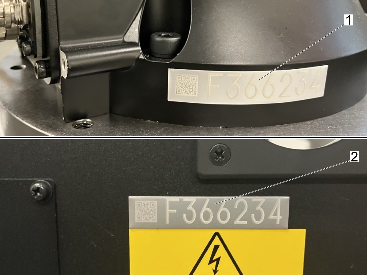
Finding Cobot F Number:

There are 2 ways to locate the F number on a Cobot:

  1. The placard on the base of the cobot below Joint-1 [1]
  2. The placard on the front door of the control box above the spec plate [2]

8

Getting Unlock Code through HBC:

The unlock code can only be obtained through HBC by a Haas Certified Technician.

On HBC press on the Service tab [1] and then find the Robot Activation transaction [2] on the left side menu.

Complete all the fields on the various steps in the activation process. 

Note: You will need information included on the activation popup as well as the serial numbers of both the Haas machine, Cobot package, and the F-number to obtain the Unlock code.

Enter the F-Number [3] and the Unlock Code [4] on the popup in order to activate the cobot.

9

After activation is successful, press [F1] to connect to the cobot again if needed.

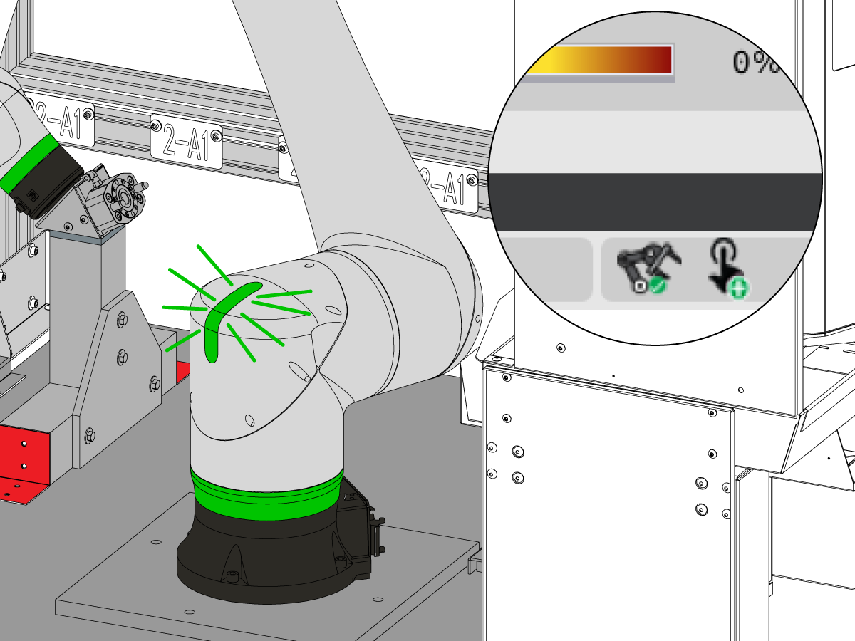
Wait for the robot icon to turn yellow or green [1]. Then release [E-STOP] and clear the alarms by pressing [RESET].

Look at the indicator light on Joint-1 on the cobot arm [2] and verify that it is green as well.

Note: If the robot icon does not turn green check to see if there are any alarms that need to be reset on the cobot teach pendent.

10

Once the cobot is connected to the Haas machine take an error report on the Haas control by pressing [SHIFT] + [F3].

It is also recommended to take an MD backup and Full image backup using the cobot teach pendent. 

Attach both the error report and the backup files to the Installation Work Order on HBC.

 Note: These error reports and backups will be referenced in case of service issues through out the life of the cobot.

Configure Grippers and Payload

1

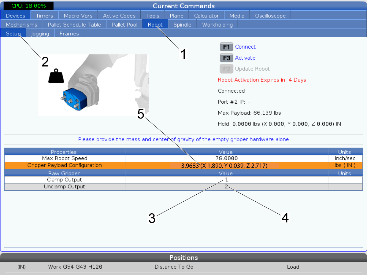
Press [CURRENT COMMANDS] button on the Haas control.

Navigate to the Devices -> Robot [1] -> Setup [2] 

Once on the Setup tab, set the Raw Gripper Clamp and Unclamp outputs:

  • Clamp Output [3] = 1
  • Unclamp Output [4] = 2

Change the Gripper Payload Configuration [5]:

  • 3.9683 (X 1.890, Y 0.039 Z 2.717)

Note: You must be connected to the cobot in order to set the gripper payload value. 

2

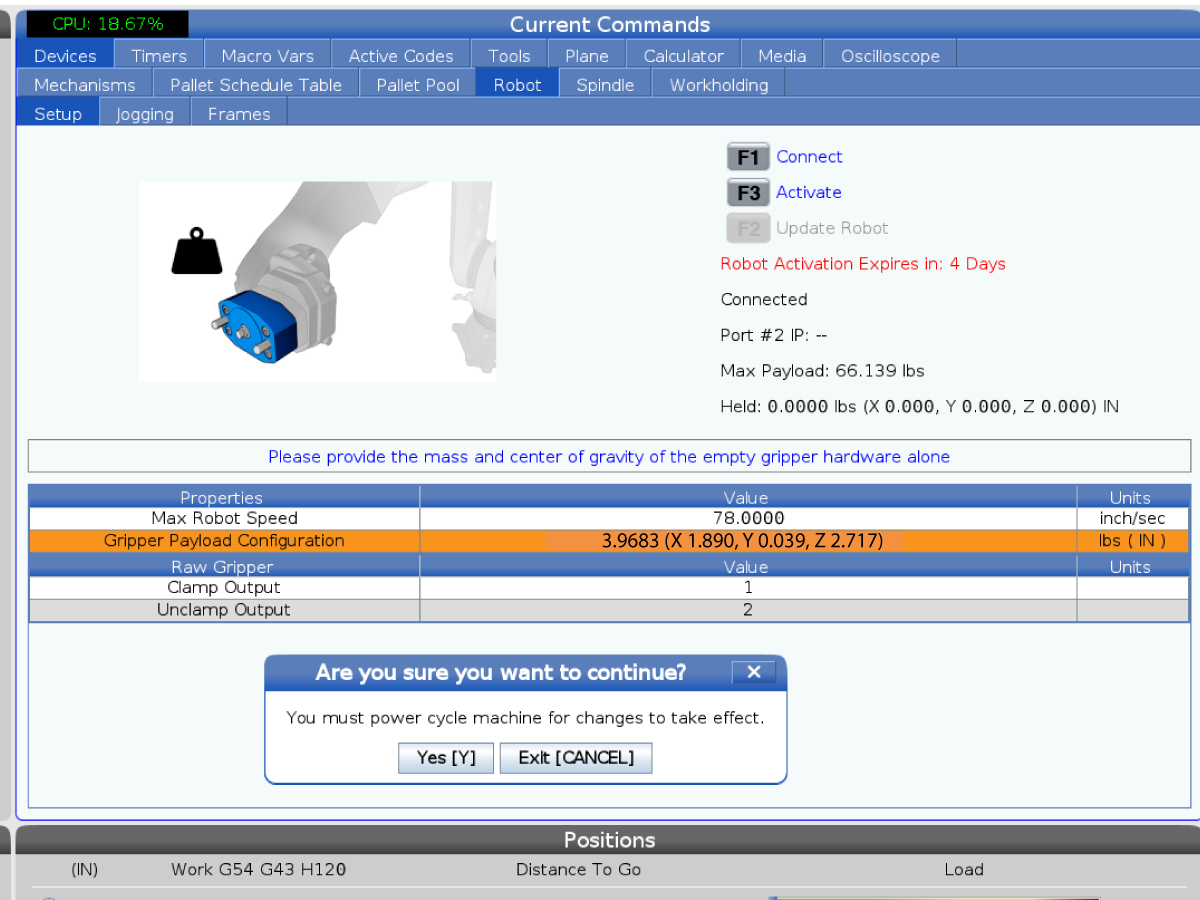
After you set the gripper payload configuration you need to wait until the cobot control box updates the payload parameters.

Wait until the Haas machine generates an alarms to cycle power on the cobot control box. Below are the alarms you should see:

  • 9150.290 SYST-290 Cycle power to use
  • 9150.212 SYST-212 Need to apply to DCS parameters

Once you get the alarms, turn the cobot control box OFF. Wait 15 seconds and then turn the control box back ON.

 Note: There will be a popup saying to cycle power the machine. The Haas machine does not need to be power cycled, only the cobot control box.

3

Once the cobot control box is back ON reset any alarms on both the teach pendent and the Haas control.

Go to the robot setup page and reconnect by pressing [ESTOP] + [F1].

Once connected the cobot indicator light should be green.

Set the Maximum Jogging Speed to:

  • 7.9 inch/sec [1]

Gripper #1 Held Payload to:

  • 3.9683 (X 1.890, Y 0.039, Z 2.717) [2]

Test the gripper by pressing [F2] [3] on the Haas control. The pullstud plug should release from the zero point gripper.

Verify Hand Guide Mode

1

Go to the Robot -> Jogging tab under current commands.

To enable Hand Guide mode from the Haas pendent, press [F4] [1]. 

You can tell that hand guide mode is active because the indicator light on the cobot will be flashing green.

While in hand guide mode, the position of each joint on the cobot can be manipulated by hand.

Move the cobot so that the gripper is facing the machine [2] and the indicator light [3] is facing the load station as shown in the image.

Once cobot is facing machine, press [F4] on the Haas pendent to disable Hand Guide mode.

Note: The hand guide mode can be toggled ON and OFF from the RJH-XL.

Verify RJH-XL

1

To jog the cobot you need to have the Remote Jog Handle - XL installed on the Haas pendent.

For more details on installing the RJH-XL refer to the AD0533 - RJH-XL Installation

After the RJH-XL is installed, press [CURRENT COMMANDS] and then navigate to Devices -> Robot -> Jogging. 

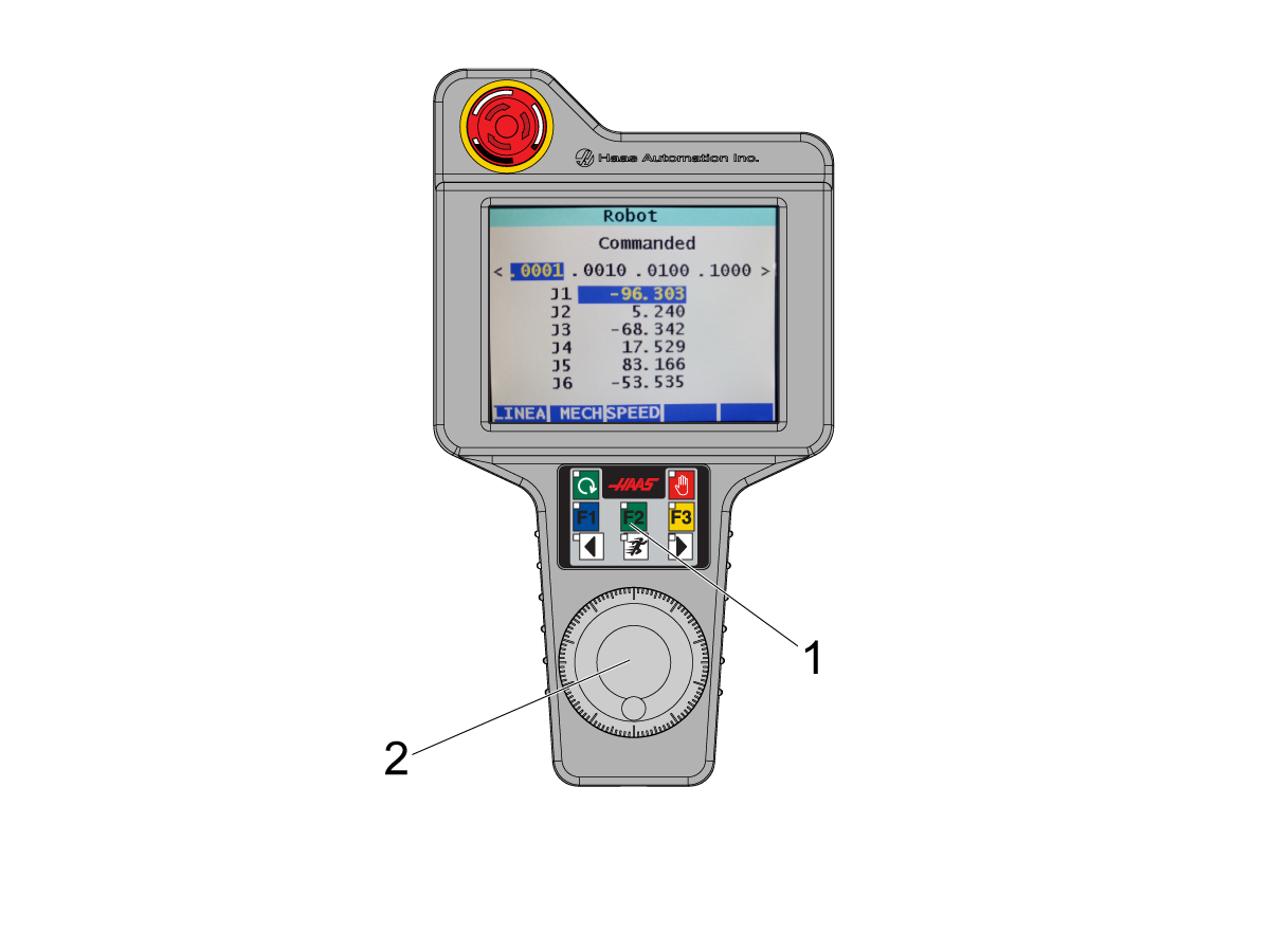
Press [HANDLE JOG] and then remove the RJH-XL from it's holster. 

Press and hold [F2] [1] while rotating the hand wheel [2]. Verify that the joint positions on the RJH display update and that the cobot moves.

Check the different speed options work as well.

2

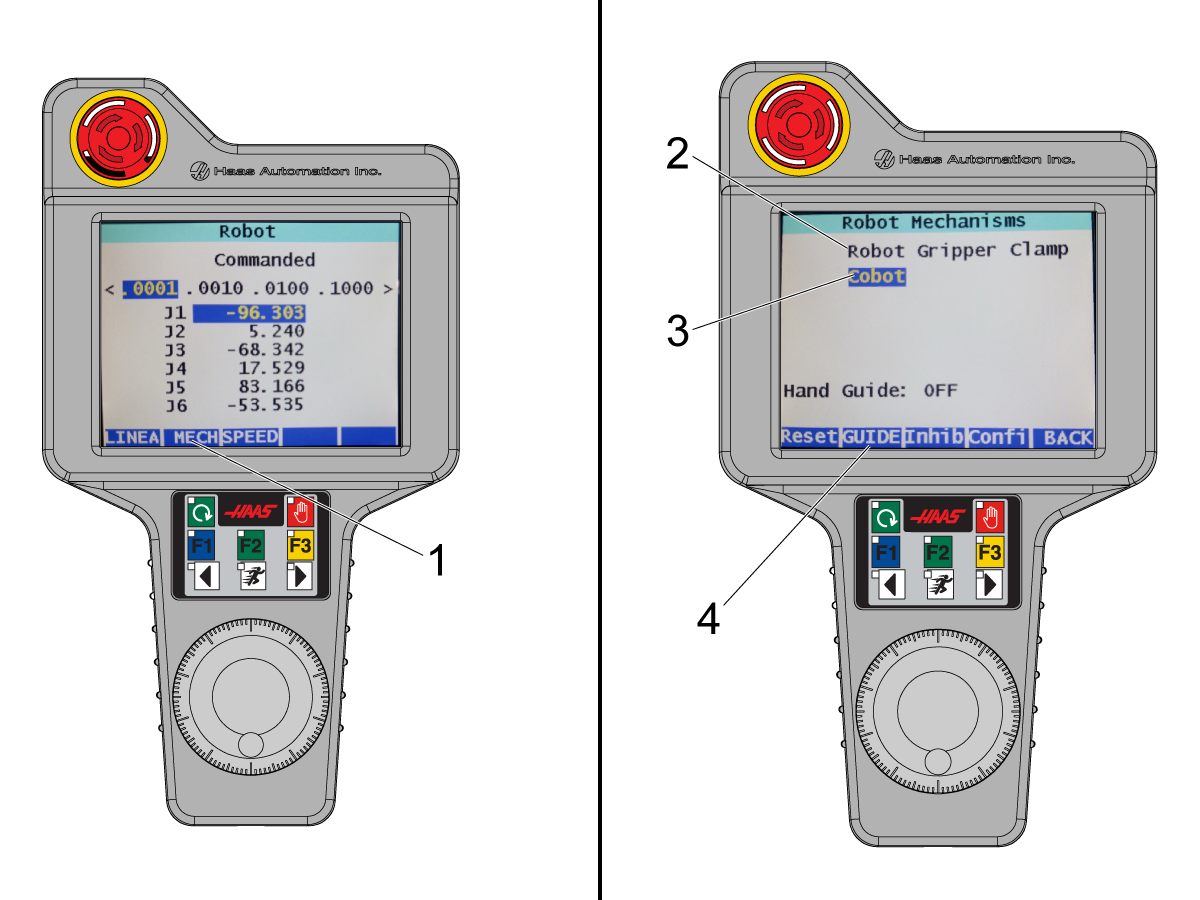
Verify that all the mechanism commands from the RJH work. 

Press [MECH] [1] on the RJH display. There are two options:

  • Robot Gripper Clamp [2]
  • Cobot [3]

Press on the Robot Gripper Clamp and test that the gripper changes state.

Press on Cobot. From here you can switch Hand Guide mode ON and OFF by pressing the Guide button [4] on the display.

 Note: You can tell the cobot is in Hand Guide mode by the indicator LED on Joint-1 of the cobot. A flashing green LED indicates Hand Guide mode is enabled.

Recently Viewed Items

You Have No Recently Viewed Items Yet

Feedback
Haas Logo

Haas Delivered Price

This price includes shipping cost, export and import duties, insurance, and any other expenses incurred during shipping to a location in France agreed with you as a buyer. No other mandatory costs can be added to the delivery of a Haas CNC Product.

KEEP UP WITH THE LATEST HAAS TIPS AND TECHNOLOGY...

Sign up now!   

HAAS TOOLING ACCEPTS THE FOLLOWING:

  • Service & Support
  • Owners
  • Request Service
  • Operator Manuals
  • Haas Parts
  • Rotary Repair Request
  • Pre-Install Guides
  • Shopping Tools
  • Build & Price a New Haas
  • Available Inventory
  • The Haas Price List
  • CNCA Financing
  • About Haas
  • Accessibility Statement
  • DNSH Statement
  • Export Compliance
  • Careers
  • Certifications & Safety
  • Contact Us
  • History
  • Terms & Conditions
  • Haas Tooling Terms & Conditions
  • Privacy
  • Warranty
  • Haas Community
  • Haas Certification Program
  • Haas Motorsports
  • Gene Haas Foundation
  • Haas Technical Education Community
  • Events
  • Join the Conversation
  • Facebook
  • X
  • Flickr
  • YouTube
  • LinkedIn
  • Instagram
  • TikTok
© 2026 Haas Automation, Inc – CNC Machine Tools

This site is protected by reCAPTCHA and the Google Privacy Policy and Terms of Service apply.

2800 Sturgis Rd., Oxnard, CA 93030
Toll Free: (888) 817-4446 / Fax: 805-278-8554