If the chip conveyor is a field install follow the Field Install section below.
If the machine is a new install with chip conveyor follow the Machine Install section below.
If you have an older style Controller Support with one plug, you will need to update to the newer style Controll Support PN 25-10700B with two plug holes.
Unplug the coolant pump cable and transfer the coolant pump plug clamp to the new controller support. Install the chip conveyor plug clamp to the new controller support.
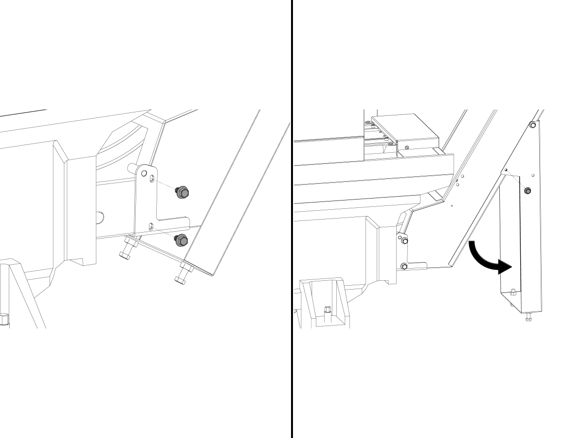
Remove the two screws that mount the controller to the support.
Remove the screws mounting the Controller support to the base casting.
Remove the screws mounting the controller support to the enclosure.
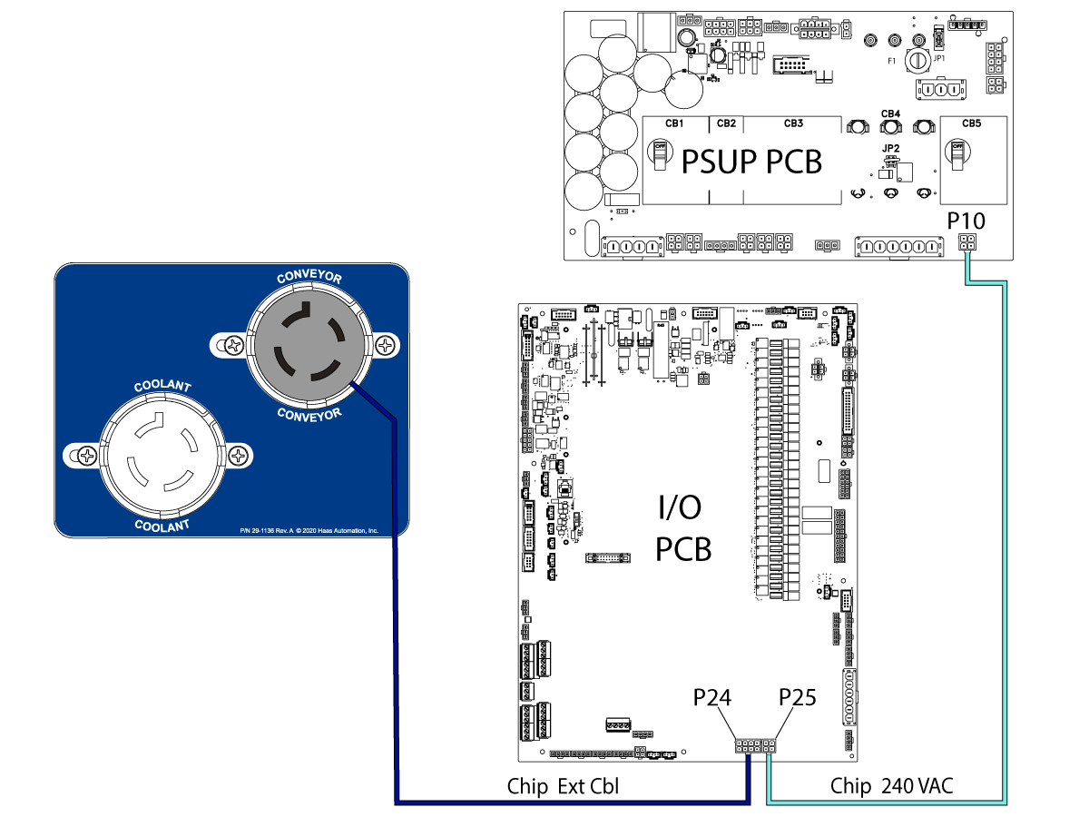
Route the chip conveyor cable from I/O P24, out the bottom of the controller and along the coolant pump cable.
Route the chip conveyor power cable from P10 on the PSUP PCB to P25 on the I/O board.
Install the new controller support and mount the controller to the new support.
Clamp the coolant pump cable and chip conveyor cable to the support. Follow the diagram for the plug locations.
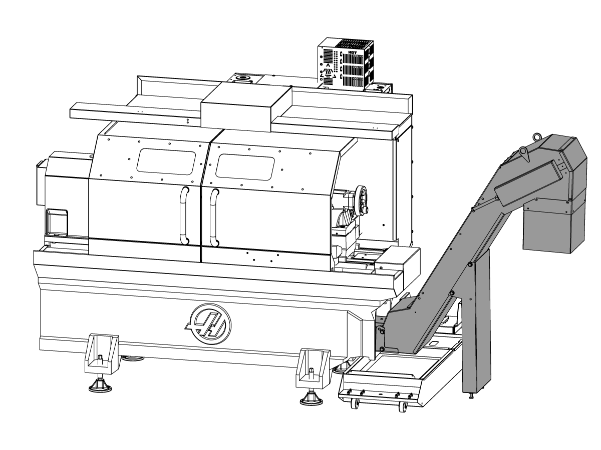
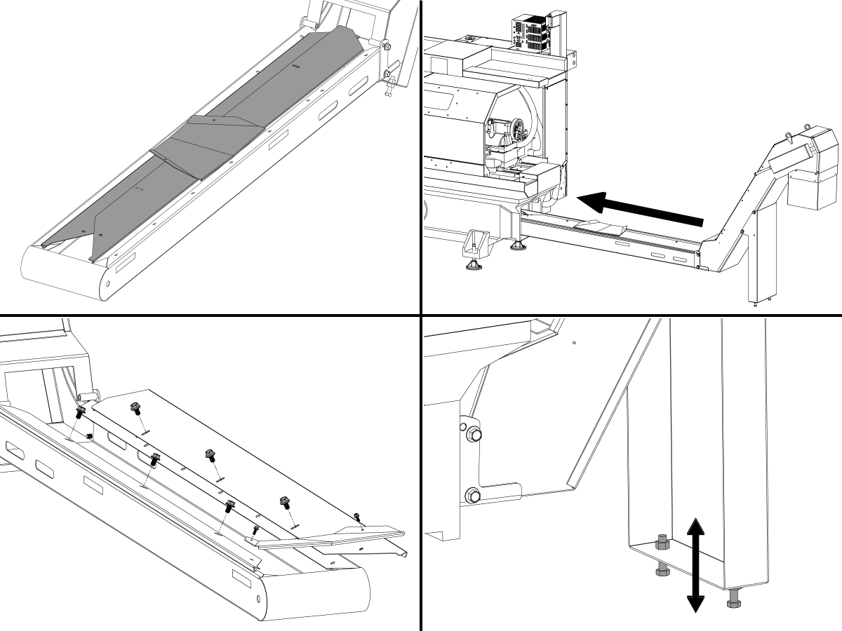
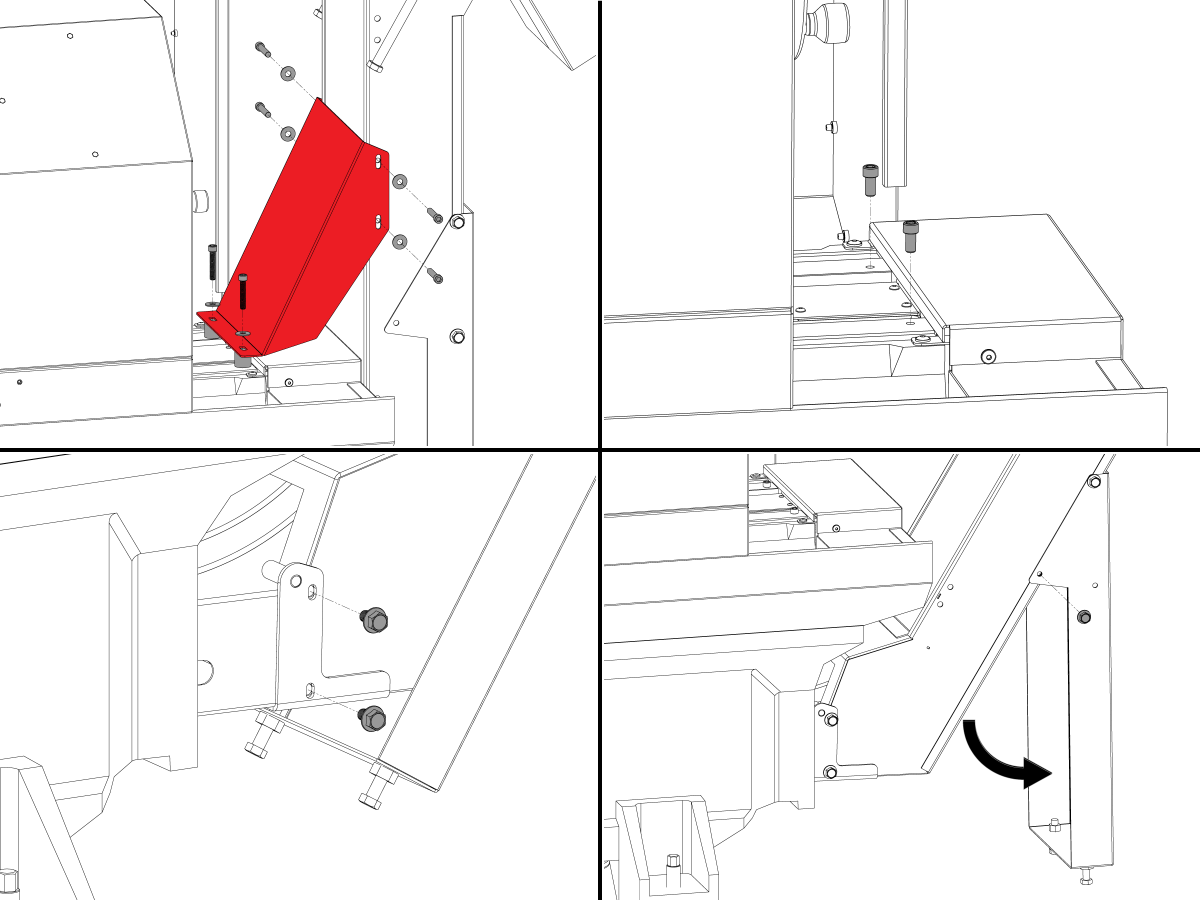
Remove the chip conveyor wings and place them on the chip conveyor and install the chip conveyor into the base.
Reinstall the chip conveyor wings to the chip conveyor and adjust until there is no gap between the casting and wings.
Remove the shipping hardware and lower the chip conveyor legs.
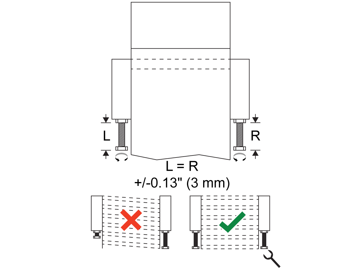
Adjust the chip conveyor legs until the chip conveyor is level.
Open the cover at the head of the conveyor. Look at the belt tension as the belt goes around the sprocket.
Loosen the motor mount hardware and tighten the belt tensioning screws at either side of the conveyor head to adjust the belt drive shaft and remove slack from the belt.
Note: Adjust the screws equally to keep the drive shaft perpendicular to belt travel.
While you adjust the belt tensioning screws, push up on the belt with a wrench at the head of the conveyor. Measure the belt slack [1] at the center of the belt in the lift section of the conveyor. The correct belt slack for Jorgensen conveyors is 0.25" - 0.38" (6 - 10 mm). The correct belt slack for Hennig conveyors is 0.12" - 0.25" (3 - 6 mm). Repeat step 2 as needed.
Apply the jam nut on each tensioning screw to lock it in place.
Tighten the motor mount hardware.
Install the access cover.
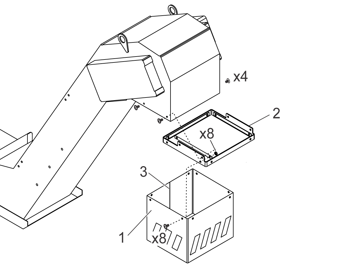
Install the chip conveyor skirt[1] to the bracket[2] and install to the chip conveyor.
Note: The seam [3] in the skirt faces the conveyor as shown.
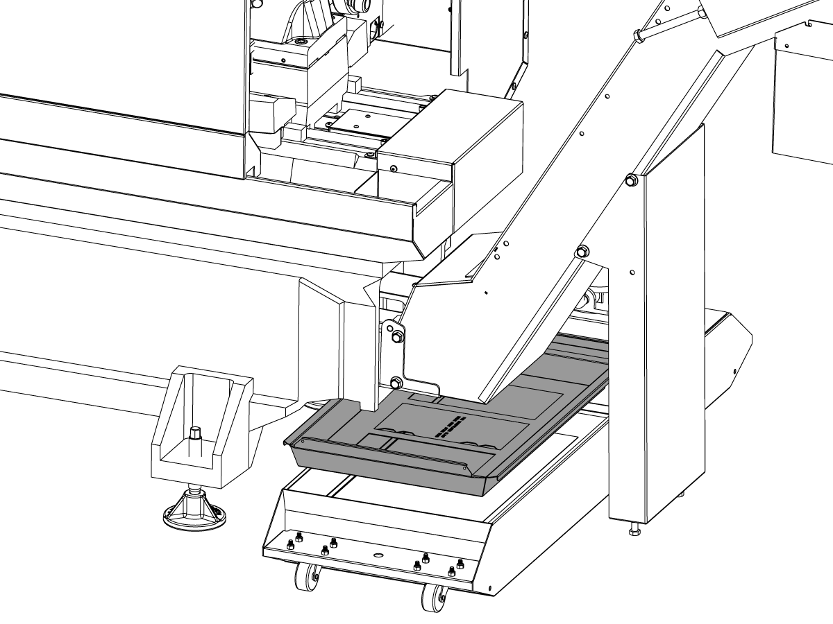
Install the new coolant tank chip tray.
Plug in the chip conveyor to the plug on the controller support.
Remove the chip conveyor shipping bracket and reinstall the tailstock stop hardware that is found inside the machine.
Install the lower bracket hardware.
Lower the chip conveyor legs to the extended position.
Pull the chip conveyor out of the base enough to place the chip conveyor wings on the chip conveyor and install the chip conveyor all the way into the base casting.
Reinstall the chip conveyor wings to the chip conveyor and adjust until there is no gap between the casting and wings.
Adjust the chip conveyor legs until the chip conveyor sits flat in the base casting.
Open the cover at the head of the conveyor. Look at the belt tension as the belt goes around the sprocket.
Loosen the motor mount hardware and tighten the belt tensioning screws at either side of the conveyor head to adjust the belt drive shaft and remove slack from the belt.
Note: Adjust the screws equally to keep the drive shaft perpendicular to belt travel.
While you adjust the belt tensioning screws, push up on the belt with a wrench at the head of the conveyor. Measure the belt slack [1] at the center of the belt in the lift section of the conveyor. The correct belt slack for Jorgensen conveyors is 0.25" - 0.38" (6 - 10 mm). The correct belt slack for Hennig conveyors is 0.12" - 0.25" (3 - 6 mm). Repeat step 2 as needed.
Apply the jam nut on each tensioning screw to lock it in place.
Tighten the motor mount hardware.
Install the access cover.
Install the chip conveyor skirt[1] to the bracket[2] and install to the chip conveyor.
Note: The seam [3] in the skirt faces the conveyor as shown.
Install the new coolant tank chip tray.
Plug in the chip conveyor to the plug on the controller support.
Install the new coolant tank chip tray.
Plug in the chip conveyor to the plug on the controller support.
Turn on the machine.
Login to the HAAS SERVICE PORTAL.
Download the Chip Conveyor option configuration patch files.
Note: The option files will appear on the configuration download page after the Chip Conveyor Kit has been ordered. If the option does not appear contact the service department.
Load the option configuration patch file to the control. Refer to the NEXT GENERATION CONTROL - CONFIGURATION FILE - DOWNLOAD/LOAD procedure.
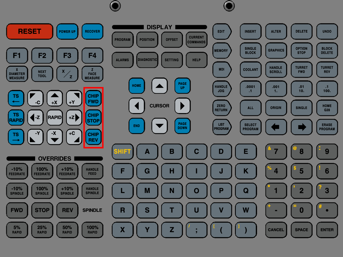
Test the chip conveyor by pressing the [CHIP FWD], [CHIP STOP], and [CHIP REV] buttons on the control pendant.