MyHaas Welkom,
!
Haas Tooling MyHaas/HaasConnect Aanmelden Aanmelden Haas Tooling MyHaas/HaasConnect Uitloggen Welkom, Mijn machines Laatste activiteit Mijn offertes Mijn account Mijn gebruikers Uitloggen
Zoek uw distributeur
  1. Taal selecteren
    1. English
    2. Deutsch
    3. Español - ES
    4. Español - MX
    5. Français
    6. Italiano
    7. Português
    8. Český
    9. Dansk
    10. Nederlands
    11. Magyar
    12. Polski
    13. Svenska
    14. Türkçe
    15. 中文
    16. Suomi
    17. Norsk
    18. الإنجليزية
    19. български
    20. Hrvatski
    21. Ελληνικά
    22. Română
    23. Slovenský
    24. Slovenščina
    25. 한국어
    26. 日本語
    27. Українська
  • machines Hoofdmenu
    • Verticale bewerkingscentra
      Verticale bewerkingscentra
      Verticale bewerkingscentra View All
      • Verticale bewerkingscentra
      • VF-serie
      • Universele machines
      • VR-serie
      • VP-5 prismatisch
      • Palletwisselaar VMC’s
      • Mini Mills
      • MoldMakers
      • Hogesnelheidsboorcentra
      • Boor/tap/frees-serie
      • Toolroom Mill Serie
      • Pocket Mill
      • Compact verticaal bewerkingscentrum
      • Portaalfreesmachine
      • SR-bladrouters
      • Extra grote VMC
      • Frezen met dubbele kolom
      • 3+2 positioneer-machines
    • Multi-asoplossingen
      Multi-asoplossingen
      Multi-asoplossingen View All
      • Multi-asoplossingen
      • Y-as-draaimachines
      • 5-assige freesmachines
    • Draaimachines
      Draaimachines
      Draaimachines View All
      • Draaimachines
      • ST-serie
      • Dubbele spil
      • Box Way-serie
      • Toolroom-draaimachines
      • Compacte draaimachine
      • Kamerfrees
      • Haas-staafdoorvoer
    • Horizontale freesmachines
      Horizontale freesmachines
      Horizontale freesmachines View All
      • Horizontale freesmachines
      • 50-conus
      • 40-conus
    • Draai- en indexeertafels
      Draai- en indexeertafels
      Draai- en indexeertafels View All
      • Draai- en indexeertafels
      • Draaitafels
      • Indexeertafels
      • 5-assige draaitafels
      • Extra lange draaitafels
    • Automatiseringssystemen
      Automatiseringssystemen
      Automatiseringssystemen View All
      • Automatiseringssystemen
      • Automatisering voor freesmachines
      • Draaimachine automatisering
      • Automatische werkstukbeladers
      • Automatiseringsmodellen
    • Desktop-machines
      Desktop-machines
      Desktop-machines View All
      • Desktop-machines
      • Desktop Freesmachine
      • Desktop draaimachine
      • Control Simulator, standaard
      • Control Simulator, Premium
    • Werkplaatsapparatuur
      Werkplaatsapparatuur
      Werkplaatsapparatuur View All
      • Werkplaatsapparatuur
      • Knie frees
      • Haas handbediende draaimachines
      • Haas-zaag
    • Fabricagemachines
      Fabricagemachines
      Fabricagemachines View All
      • Fabricagemachines
      • Lasersnijmachines
      • CNC-persremmen
    • SNELKOPPELINGEN Speciale serie  Speciale serie 
      EU-SERIE EU-SERIE SAMENSTELLEN EN PRIJS BEPALEN | PRIJSLIJST SAMENSTELLEN EN PRIJS BEPALEN | PRIJSLIJST Machines op voorraad Machines op voorraad WAT IS ER NIEUW WAT IS ER NIEUW UW EERSTE CNC UW EERSTE CNC
      WINKELEN VOOR GEREEDSCHAP
      • Een Haas samen stellen en de prijs bepalen
      • Prijslijst
      • Beschikbare voorraad
      • CNCA financiering
      WILT U MET IEMAND SPREKEN?

      Een Haas Factory Outlet (HFO) kan uw vragen beantwoorden en de beste mogelijkheden met u bespreken.

      CONTACT YOUR DISTRIBUTOR >
  • Opties Hoofdmenu
    • The Haas Control Waardeoptiepakketten
      Waardeoptiepakketten
      Waardeoptiepakketten View All
      • Waardeoptiepakketten
    • Product Image Spillen
      Spillen
      Spillen View All
      • Spillen
    • Product Image Gereedschapswisselaars
      Gereedschapswisselaars
      Gereedschapswisselaars View All
      • Gereedschapswisselaars
    • Product Image 4e- | 5e-as
      4e- | 5e-as
      4e- | 5e-as View All
      • 4e- | 5e-as
    • Product Image Revolvers en aangedreven gereedschappen
      Revolvers en aangedreven gereedschappen
      Revolvers en aangedreven gereedschappen View All
      • Revolvers en aangedreven gereedschappen
    • Product Image Tasten
      Tasten
      Tasten View All
      • Tasten
    • Haas beheer van spanen en koelmiddel Beheer van spanen en koelmiddel
      Beheer van spanen en koelmiddel
      Beheer van spanen en koelmiddel View All
      • Beheer van spanen en koelmiddel
    • De Haas besturing De Haas besturing
      De Haas besturing
      De Haas besturing View All
      • De Haas besturing
    • Product Image Productopties
      Productopties
      Productopties View All
      • Productopties
    • Product Image Gereedschap en opspanning
      Gereedschap en opspanning
      Gereedschap en opspanning View All
      • Gereedschap en opspanning
    • Product Image Werkstukopspanning
      Werkstukopspanning
      Werkstukopspanning View All
      • Werkstukopspanning
    • Product Image 5-assige oplossingen
      5-assige oplossingen
      5-assige oplossingen View All
      • 5-assige oplossingen
      • 5 Easy Steps to 5-Axis
    • Product Image Automatisering
      Automatisering
      Automatisering View All
      • Automatisering
    • SNELKOPPELINGEN Speciale serie  Speciale serie 
      EU-SERIE EU-SERIE SAMENSTELLEN EN PRIJS BEPALEN | PRIJSLIJST SAMENSTELLEN EN PRIJS BEPALEN | PRIJSLIJST Machines op voorraad Machines op voorraad WAT IS ER NIEUW WAT IS ER NIEUW UW EERSTE CNC UW EERSTE CNC
      WINKELEN VOOR GEREEDSCHAP
      • Een Haas samen stellen en de prijs bepalen
      • Prijslijst
      • Beschikbare voorraad
      • CNCA financiering
      WILT U MET IEMAND SPREKEN?

      Een Haas Factory Outlet (HFO) kan uw vragen beantwoorden en de beste mogelijkheden met u bespreken.

      CONTACT YOUR DISTRIBUTOR >
  • Why Haas Hoofdmenu
      Ontdek het verschil dat Haas maakt
    • Waarom Haas
    • MyHaas
    • Onderwijscommunity
    • Industrie 4.0
    • HAAS-CERTIFICERING
    • Ervaringen van klanten
  • Service Hoofdmenu
      Welkom bij Haas Service
      SERVICE HOME Bedieningshandleidingen Instructieprocedures Gidsen voor het verhelpen van storingen Preventief onderhoud Haas-onderdelen Haas Tooling Video’s
  • Video’s Hoofdmenu
  • Haas-gereedschap Hoofdmenu
MyHaas Welkom,
!
Haas Tooling MyHaas/HaasConnect Aanmelden Aanmelden Haas Tooling MyHaas/HaasConnect Uitloggen Welkom, Mijn machines Laatste activiteit Mijn offertes Mijn account Mijn gebruikers Uitloggen
Zoek uw distributeur
  1. Taal selecteren
    1. English
    2. Deutsch
    3. Español - ES
    4. Español - MX
    5. Français
    6. Italiano
    7. Português
    8. Český
    9. Dansk
    10. Nederlands
    11. Magyar
    12. Polski
    13. Svenska
    14. Türkçe
    15. 中文
    16. Suomi
    17. Norsk
    18. الإنجليزية
    19. български
    20. Hrvatski
    21. Ελληνικά
    22. Română
    23. Slovenský
    24. Slovenščina
    25. 한국어
    26. 日本語
    27. Українська
×

Resultaten zoekopdracht

Web Pages

Images

    • <
    • 1
    • >

Geometry Guide - UMC - Series

Service Home Instructieprocedure Geometry Guide - UMC - Series

Geometry Guide - UMC - Series

- Spring naar sectie - Back to Top

8.1 Geometrie Gids

Recently Updated Last updated: 04/07/2021

Geometrie gids -UMC-serie


Inleiding

  1. Spindel hoofd
  2. Ram
  3. Zadel
  4. Brug
  5. Basis
  6. C-as Rotary
  7. B-as Rotary

Voordat u begint met het opnemen van de fabriek-stelt u de waarde voor de parameter of instelling hieronder. U moet dit instellen op nul tijdens het maken van aanpassingen en vervolgens opnieuw instellen op de oorspronkelijke waarde wanneer u klaar bent. De waarde kan positief of negatief zijn.

  • Klassieke Haas-bediening (CHC) Parameter 1314 (Rotary Axes Center Deviation in X)
  • Controle van de volgende generatie (NGC) Instelling 254 (5 Axis Rotary Center Distance)

Gereedschap en kits vereist:

  • T-2193A - UMC-750 SPINDLE HEAD ALIGNMENT PIN *
  • T-2181- CNC DUAL LEVELING TOOL
  • T-2192- LEVELING ADAPTER UMC-750
  • 93-2236 - SHIM KIT FOR UMC-750 *

Klik op de link om de  UMC-750 nivellering en uitlijning Video.

*  : Alleen gebruikt in de Pre-Reboot-serie. 

Niveau van de machine

1

Stel de hoogte van de machine in:

Verplaats de X-en Y-as naar de beginpositie.

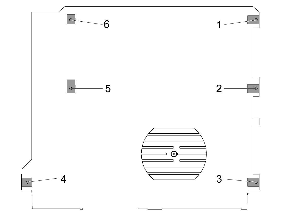
Draai de middelste nivelleringsschroeven [2 en 5] los zodat ze geen enkel gewicht ondersteunen.

Stel de machine in op 4 hoek-nivelleringsschroeven 3" (76,2mm) boven de grond.

2

Ruw niveau van de machine:

Draai de nivellerings schroef #4 omhoog.

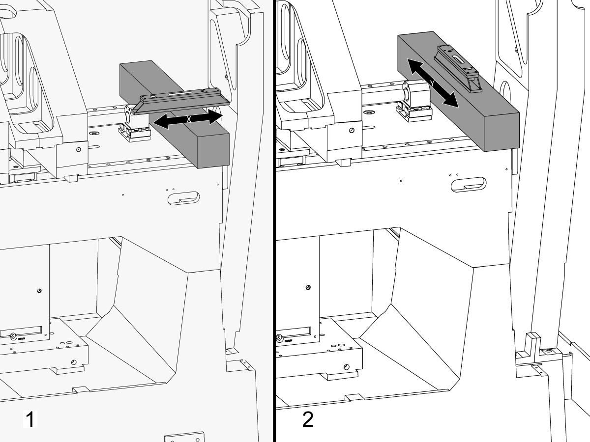
Plaats het graniet over de X-as lineaire geleiders in de buurt van de X-as kogellagers steun.

Stel het machinist niveau bovenop het graniet parallel aan de X-as in. 1

Pas de nivellerings schroef #6 totdat de machine in de X-as is genivelleerd.

Stel het machinist niveau bovenop het graniet loodrecht op de X-as. 2

Pas de nivellerings schroef #3 totdat de machine in de Y-as is genivelleerd.

Draai de nivelleringsschroef #4 naar beneden tot deze het contact met de stelpoot maakt.

3

X-as-rol aanpassen:

Monteren T-2192 met T-2181.

Verplaats de Y-as naar het midden van de reis.

Zet de T-2192 aan de zijkant van de spil.

Zorg ervoor dat de bel op de T-2181 zich binnen een leesbaar bereik bevindt.

Als dat niet het is, draai de bout die de T-2192 beveiligt aan op de magnetische voet en verplaats de adapter naar behoefte.

JOG de X-as aan de zijkant en meet de rol van de X-as. Neem lezingen op de thuispositie, het midden en het einde van de reis.

Pas de nivellerings schroef #4 tot er is geen afwijking tussen de meting aan de uitgangspositie en de meting aan het einde van de reis.

Opmerking: De bel op de T-2181 hoeft niet in het midden van de injectieflacon te staan. Het hoeft alleen binnen een leesbaar bereik te zijn.

4

Stel de middelste nivelleringsschroeven in:

Draai middelste nivelleringsschroeven naar beneden totdat ze het contact met de stelpoten maken en zet ze vervolgens een extra 45 °.

Controleer de rol van de X-as. Pas de middelste nivelleringsschroeven aan om de rol van de X-as te corrigeren.

X-as naar Y-as uitlijning

1

Lijn het vlak van het zadel parallel met de beweging van de X-as uit:

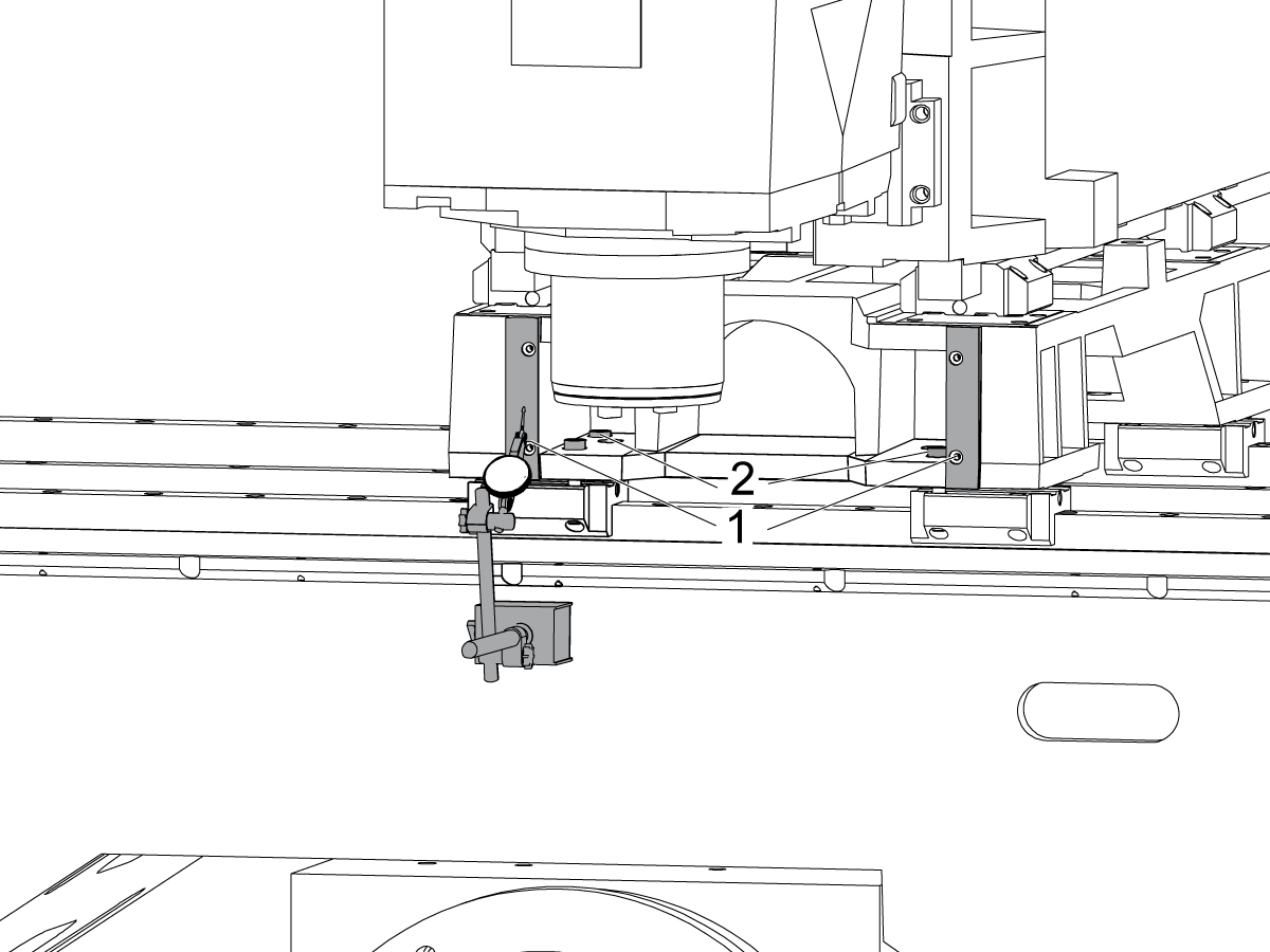
Veeg over het bewerkte oppervlak aan de voorkant van het zadel [1] door de X-as te joggen.

Draai de bouten los die het zadel op de X-as Trucks [2] zetten en lijn het vlak van het zadel parallel met de X-as beweging uit binnen 0,001" indien nodig.

Koppel de bouten. Verwijzen naar Haas Bevestigingsmoment specificaties.

2

Lijn de Y-as loodrecht op de X-as uit:

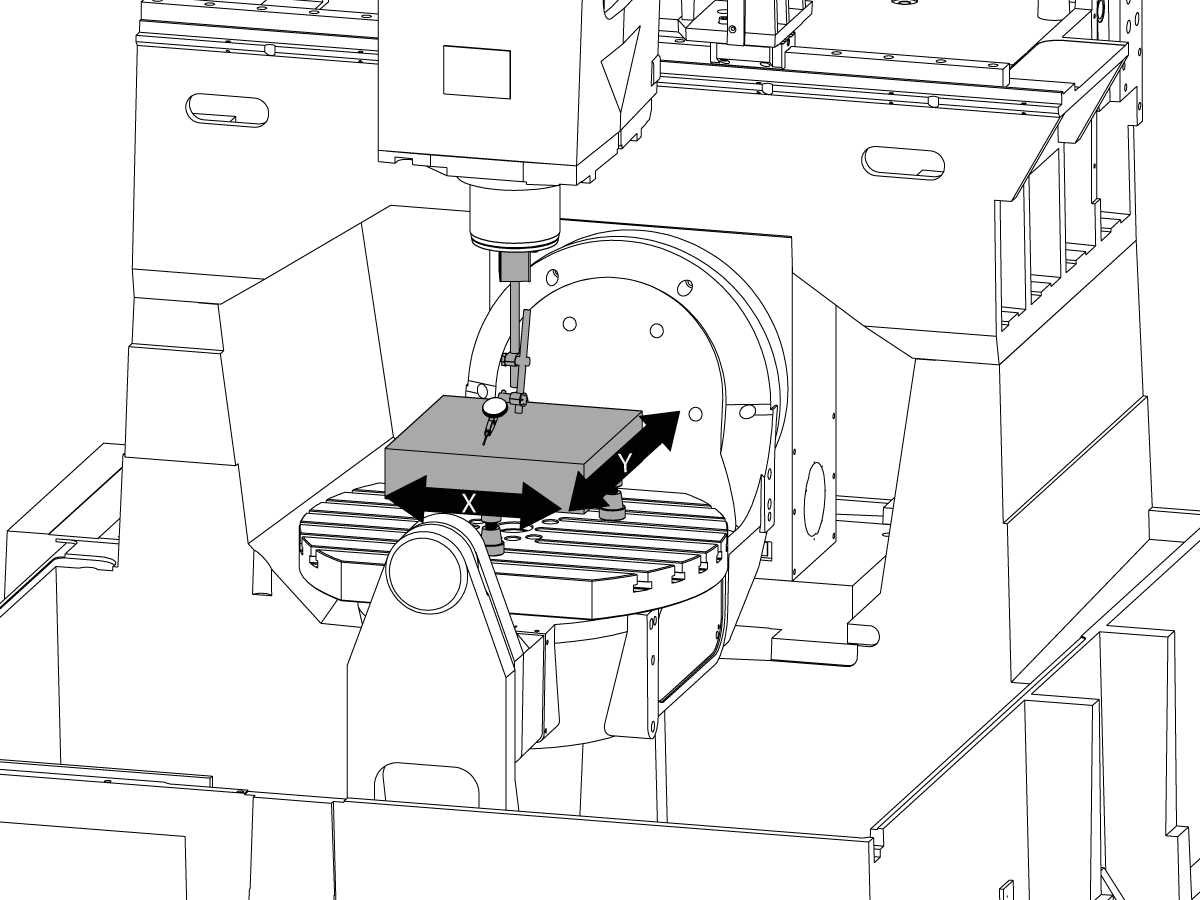
Stel de Tri-Square graniet op de linker kant van de C-as platter op de machinist Jacks.

Stel de achterzijde van het Tri-Square graniet parallel aan de X-as. NTE 0,0001"/10"

Veeg de bovenkant van het Tri-Square graniet langs de X-en Y-assen.

Pas de machinist-Jacks aan tot het bovenste oppervlak van het Tri-Square graniet evenwijdig is aan het X-Y-vlak NTE 0,0005".

Controleer of de achterzijde van het graniet parallel aan de X-as. NTE 0,0001"/10".

Draai de bouten los die de Y-as trucks aan het zadel hebben vast en lijn de Y-as loodrecht op de X-as uit. NTE 0,0005"/10"

Koppel de bouten. Verwijzen naar Haas Bevestigingsmoment specificaties.

Controleer de Y-as loodrecht op de X-as NTE 0,0005"/10" Nadat de bouten zijn torqued.

Z-as naar de X-Y-vlak uitlijning

1

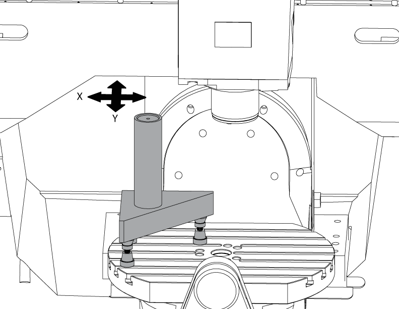
Stel de cilinder in.

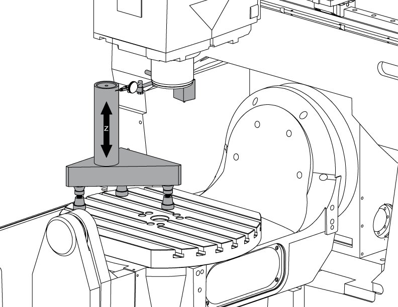
Zet een cilinder bovenop de Tri-Stone zoals afgebeeld op de foto.

Lijn het bovenste oppervlak van de cilinder parallel aan X-Y-vlak NTE 0,0001" door het draaien van de machinist Jacks.

JOG de machine op de volgende positie:

  • UMC-750 tot X-7,000" en Y-10,000"
  • UMC-750SS naar X-10,000" en Y-10,000"

2

Lijn de Z-as loodrecht op de X-as uit:

Vervang een van de bovenste hoek bouten op de Z-as trucks met de T-2193A * om de spil met de kop eromheen te draaien.

Geef de zijkant van de cilinder langs de Z-as aan.

Draai de bouten die Z-as trucks aan het RAM-geheugen beveiligen los.

Lijn de Z-as loodrecht op X-as NTE 0,0005"/10" door de spilkop heen en weer te bewegen.

Koppel de bouten. Verwijzen naar Haas Bevestigingsmoment specificaties.

Controleer of de Z-as loodrecht op de X-as na bouten torqued.

Vervang de T-2193A * door de bout wanneer de uitlijning is voltooid

*  : Alleen gebruikt in de Pre-Reboot-serie. 

3

Lijn de Z-as loodrecht op de Y-as uit:

Geef de voorkant van de cilinder langs de Z-as aan.

Shim tussen Z-as trucks en de RAM om de Z-as loodrecht op de Y-as af te stemmen NTE 0,0005"/10".

Opmerking: Shim ofwel top twee trucks of de onderste twee trucks met de gelijke shims.

Koppel de bouten. Verwijzen naar Haas Bevestigingsmoment specificaties.

Controleer of de Z-as loodrecht op de Y-as en de X-assen na bouten torqued.

4

Uitlijnen en koppel Y-en Z-assen kogelomloopmoer behuizingen:

Draai de bouten die de balmoer aan de behuizing en bouten die de behuizing aan de casting vast te zetten.

Knus de bouten die de kogelomloopmoer behuizing aan de casting eerst vast te zetten, dan knus de bouten die kogelomloopmoer aan de behuizing te beveiligen.

Gebruik de jobvergrendelingsfunctie om de as heen en weer te draaien vol reizen.

Opmerking: Gebruik het handwiel of de Rapid Move niet.

Koppel de bouten. Verwijzen naar Haas Bevestigingsmoment specificaties.

De Y-as moer behuizing is toegankelijk in de achterzijde van de machine, waarbij de RAM helemaal naar de voorkant van de machine wordt gevoerd.

De Z-as moer behuizing kan worden benaderd vanaf de voorkant van de machine met de spil hoofd afgelegd helemaal naar beneden.

Opmerking: Spindel motor lijkwade moet worden verwijderd om toegang te krijgen tot de Z-as kogelomloopmoer behuizing.

Tram de spil naar het X-Y-vlak

1

Het graniet instellen:

Instellen van de machinist Jacks en het graniet op het midden van de C-as platter zoals getoond in de afbeelding.

Lijn het bovenste oppervlak van het graniet parallel aan X-Y vlak door het aanpassen van de machinist Jacks hoogte NTE 0,0001".

Plaats de spil over het midden van het plateau.

2

Tram de spil naar het X-Y-vlak:

Plaats een indicator op de spil schacht.

Maak een meting bovenop het graniet bij elke rotatie van 90 °.

Draai de (6) bouten in de basisplaat van de spilkop los.

Toevoegen of verwijderen van shims tussen de spil hoofd gieten en de basisplaat aan de tram de spil naar het X-Y-vlak NTE 0,0005"/10".

Opmerking: Gebruik shims van ongelijke dikte [1] om de hoek van de basisplaat te veranderen.

Wanneer de sweep binnen de specificatie is, koppel de (6) bouten. Verwijzen naar Haas Bevestigingsmoment specificaties.

Controleer de spil tram nadat de bouten torqued zijn.

B-as naar XYZ-assen uitlijnen

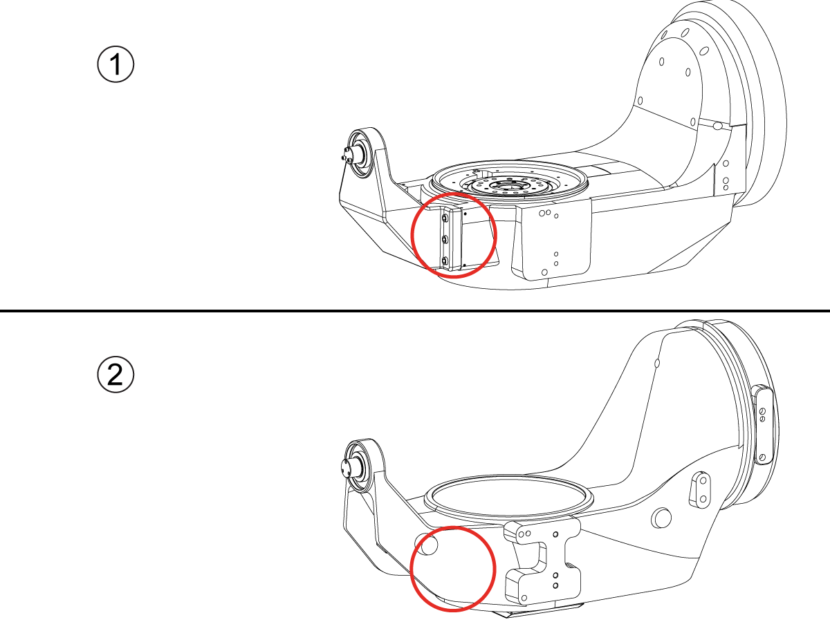
How to identify the Multi-Piece and the Unibody trunnion   

1) Multi-Piece trunnion:    UMC machines built approximetely before 11/2022 will have this configuration.

2) Unibody trunnion:    UMC machines built approximetely after 11/2022 will have this configuration.

1

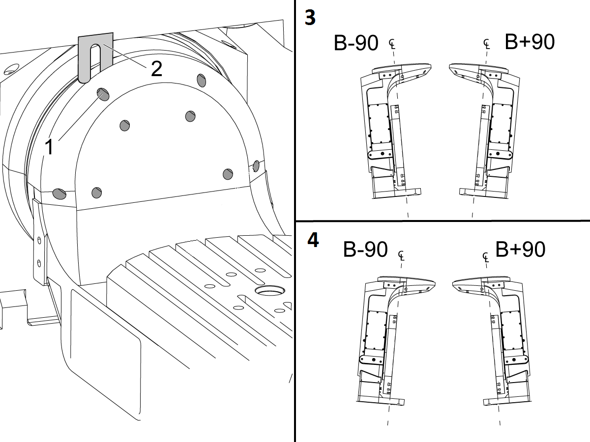
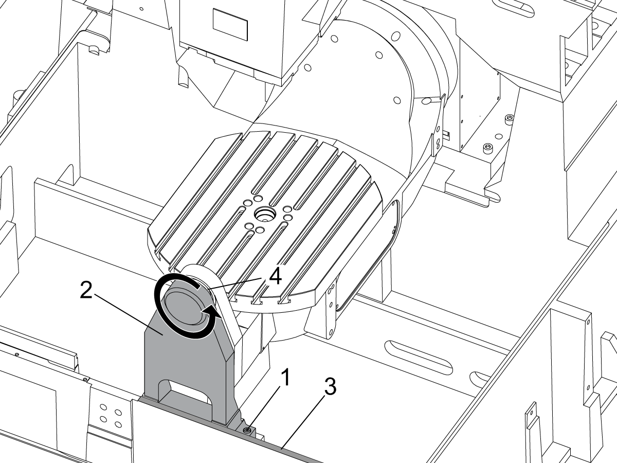
Remove the A-frame trunnion support:

Remove the bolts [1] that secure the A-frame trunnion support [2] to the base and take out the shims between A-frame support and the base.

Rotate the A-frame support [2] counter-clockwise to clear the edge of the base [3].

Pull the A-frame support off the bearings.

 Note: The A-frame support might vacuum lock on the bearings. Use the zip-tie to pry the seal [4] open.

 Caution: To lift the trunnion support, get the aid of another person. The support weighs 85 lbs (39 kg).

2

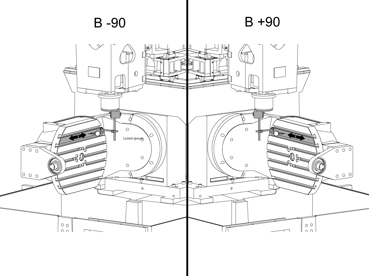
Measure the B- axis of rotation parallelism to the Y-Z plane:

For a machine with a Classic Haas Control, change Parameter 151:20 (B axis CHK TRAVL LIM) to 0.

For a machine with a Next Generation Control, change Parameter 6.021 (B axis CHK TRAVL LIM) to FALSE.

Measure the parallelism of the platter to the Y-Z plane with the B axis at 90° and then the B axis at -90° as shown in the picture.

Position the Y-Axis in the following starting position:

UMC-500: Y=0, Sweep 15”, 3rd T-Slot Land from the top.

UMC-750/1500-Duo: Y=-1.0, Sweep 18", 3rd T-Slot Land from the Top .

UMC-1250: Y=-1.0, Sweep 28", 3rd T-Slot Land from the Top.

UMC-500PP: Y=-4.0, Sweep 7".

UMC-750PP: Y=-2”, Sweep 15".

UMC-1000PP: Y=-4”, Sweep 15".

Compare the results at B 90° and B-90°. The results should be...

  • Symmetric against the Y-Z plane, positive or negative direction
  • Less than 0.0010"/20"

If the results are symmetric against Y-Z plane, and are less than 0.0010"/20 inches: Go to Step 5.

If the results are symmetric against Y-Z plane, but are more than 0.0010"/20 inches: Go to Step 4.

 Warning: If the results [3] are not symmetric against the Y-Z plane, the B axis rotary needs to be aligned: Go to Step 3.

3

Align the B axis of rotation parallel to the Y-Z plane:

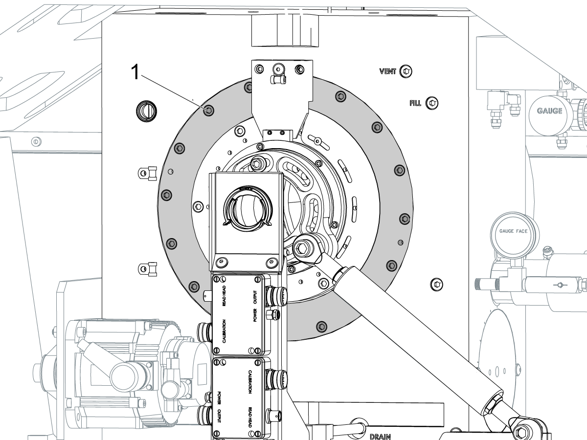
Loosen the (6) bolts [1] that secure the B axis rotary to the base casting.

 Note: Keep the bolts sufficiently snug to control the adjustments.

Adjust the front and rear setscrews [2] until the measurements taken in Step 2 are symmetric against the Y-Z plane.

Torque the (6) bolts [1]. Refer to Haas Fastener Torque Specification.

Verify the measurements in Step 2 after the bolts have been torqued.

4

Align the C Axis of rotation perpendicular to the B Axis of rotation:

Remove the bottom C-Axis access cover.

Loosen the (12) bolts [1] that hold the C Axis body to the B Axis platter face.

Reach the bottom (4) bolts through the C Axis access port.

If the B Axis is symmetric in the positive direction [4], install horseshoe shims [2] of appropriate size behind the top (2) bolts.

If the B Axis is symmetric in the negative direction [5], install horseshoe shims [2] of appropriate size behind the bottom (2) bolts.

Torque the (12) bolts to 80 Ft-lbs (108 Nm).

Cut the excessive shim material off.

Verify the measurements in Step 2 after bolts are torqued.

5

Align the trunnion support shaft co-axial with the B Axis of rotation:

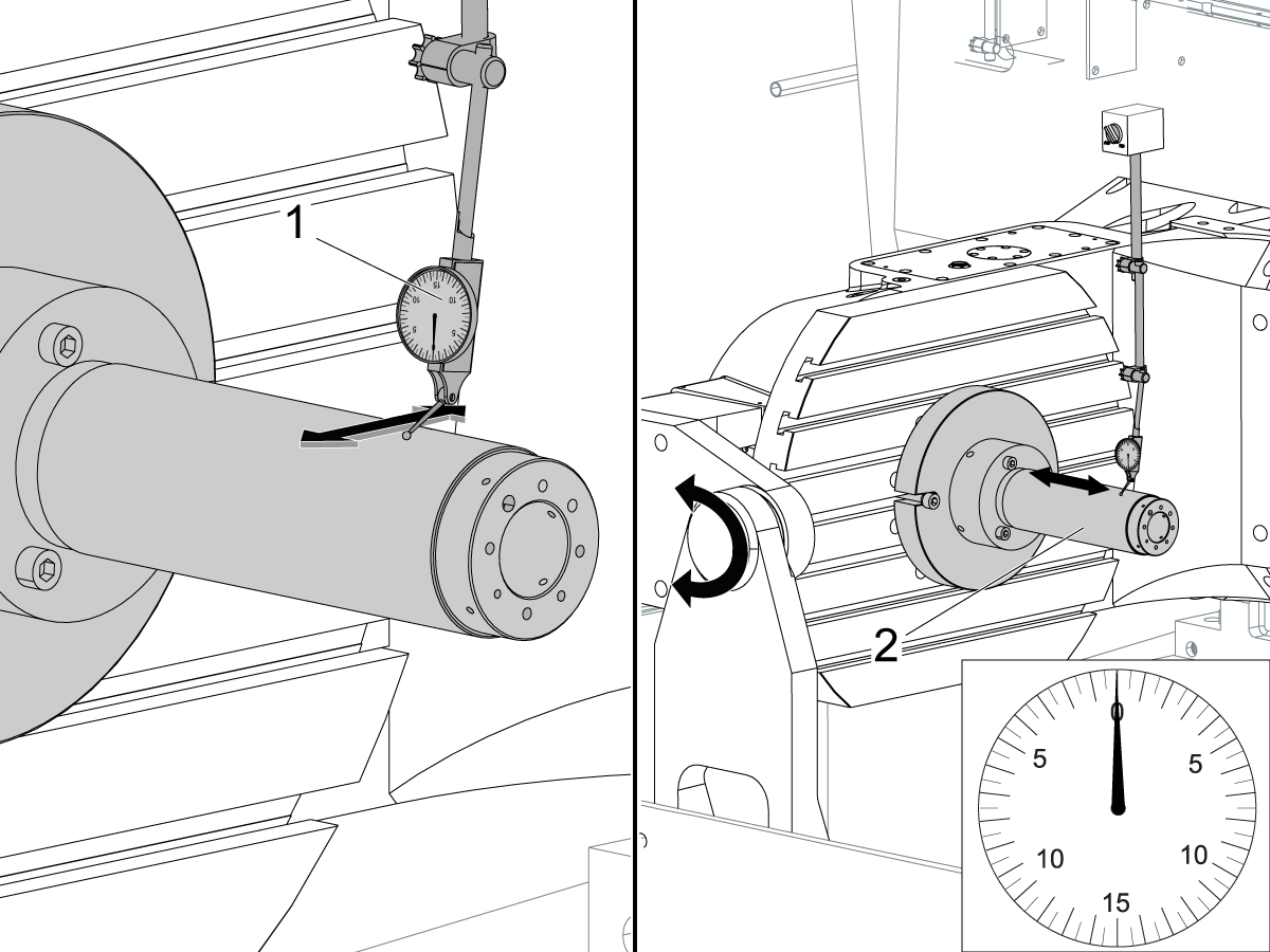
Setup (2) indicators on the outer race of the trunnion support bearing [2] as shown in the picture.

Mark the spot on the outer race where one of the indicator needles is contacting the surface.

After moving the B Axis to 90° or -90° you will align the marked spot with the needle again to exclude the bearing runout error from the measurements.

Take the readings when B is at 90° and B at -90°. Compare the readings. 

 Caution: The B axis brake needs to be clamped when taking the readings.

The deviation between the results when B is at 90° and at -90° needs to be less than 0.001" on each indicator.

 Note: The indicator on the side of the bearing will measure top to bottom alignment and the indicator on the top of the bearing will measure side to side alignment.

____

For models with a multi-piece trunnion

Loosen the (6) bolts [3] on the C Axis body support. Keep the bolts sufficiently snug to control adjustment.

Adjust the (8) set screws [4] until deviation between B at 90° and B at -90° is within 0.001".

Torque the (6) bolts [2] on the C Axis body support to 80 Ft-lbs (108 Nm).

Verify the alignment after the bolts have been torqued.

____

For models with a unibody trunnion

Jog rotary to B90. Set up an indicator on the highlighted surface as shown in the lower diagram .

Rotate B-axis 180 degrees (90 to -90).

Run out (NTE 0.010” TIR).

 Caution: If the measurement exceeds the tolerance then contact support.

6

Install and shim the A-frame trunnion support:

Move the B Axis to 90°.

Setup an indicator [1] against a machined surface of the C Axis body. Set the indicator to 0.

Use plastic zip ties [2] to pry the seal open while installing the A-frame support. This lets unwanted air and grease out of the assembly.

Install the A-frame trunnion support [3] over the bearings.

Remove the cable ties.

Turn the trunnion support clockwise until it is vertical.

 Note: The weight of the A-frame support will cause the trunnion to sag. The amount of sag is measured with the indicator that was previously setup on the side of the C Axis body.

____

For multi-piece trunnions

Adjust the shims [4] between the A-frame support and the base casting to remove the sag until indicator reads 0 again.

When the indicator reading is 0, torque the (4) bolts. Refer to Haas Fastener Torque Specification.

Verify the reading after bolts are torqued. Adjust the shims again if necessary until the indicator reads 0.

____

For models with unibody trunnion

Determine the amount of shim stock [4] needed to raise the Trunnion arm so the indicator reads 0.005".

The indicator [1] value will change once the support is torqued.

With indicator still in place:

  • Torque trunnion support bolts to appropriate values.
  • Check indicator to make sure it reads between the range of

Trunnion arm raised (0.005” to  0.010”).

 Note: For unibody trunnions, the shim location may also be used to correct the C-axis to X-Y plane perpendicularity instead of shimming the saddle trucks.

 Caution: Use equal amount of shims on each side of the A-frame support. Unequal shims will cause the A-frame support to pull the trunnion to the side.

Verify the B Axis of rotation alignment to the Y-Z plane (Step 2). Loosen the bolts and tap the A-frame support side to side if necessary to correct the B axis to Y-Z plane alignment.

7

Set C-axis perpendicular to X/Y plane:

Move the axes to

UMC-750's........X= -10.5" & Y=0."

UMC-1000's......X=-17.0" & Y=-0."

Zero an indicator [1], on a Ground Block [2], 1/2" off the edge at the rear of the platter (Mag-Base on Spindle), with C at 0 Degrees

Rotate C-Axis to 180°.

Move Y axis, and ground block, in Y Axis negative direction until you are 1/2" away from platter edge, and take the perpendicularity measurement

Adjust the shims until the average error is within 0.0005" end to end.

 Note: For unibody trunnions, the shim location under the bearing support may also be used to correct the C-axis to X-Y plane perpendicularity instead of shimming the saddle truck.

Caution: Shim either two front trucks or two rear trucks with the equal shim.

Note: Shim one truck at the time to maintain the X to Y squareness.

Verify the measurements after all bolts are torqued.

Verify the X to Y alignment in Step 2.

8

Set the tool change offsets:

B-axis tool change offset [1]

For Classic Haas Controls, change Parameter 213. 

For Next Generation Controls, go to: Settings>Rotary Tab>Highlight the rotary and press [INSERT], or change Parameter 6.078 (B TOOL CHANGE OFFSET) to set the trunnion (B Axis) parallel to the X Axis.

For models with multipiece trunnion

(NTE 0.001/10"; NTE 0.0020" overall)

For models with unibody trunnion

(NTE 0.0005/10"; NTE 0.0010" overall)

___

C-axis tool change offset [2]

For Classic Haas Controls change Parameter 523.

For Next Generation Control go to: Settings>Rotary Tab> Highlight the rotary and press [INSERT], or change Parameter 7.078 (C TOOL CHANGE OFFSET) to set the table T-slot (C Axis) parallel to the X Axis

For models with multipiece trunnion

(NTE 0.001/10"; NTE 0.0020" overall)

For models with unibody trunnion

(NTE 0.0005/10"; NTE 0.0010" overall)

9

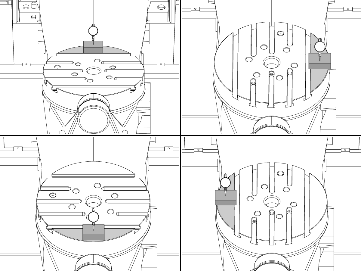
Check C-axis perpendicularity to X/Y plane:

Align the indicator centered over the C-axis bore with the Y-axis at -10.

Jog positive in the Y-axis and align the indicator over the center of the last section of the platter and make a mark at this spot with a washable marker.

Insert 1-2-3 block as shown and set the indicator to zero.

Remove the block and rotate the platter 90 degrees, following the marked spot with the indicator.

Insert block back between the indicator and platter. Note reading.

Repeat the previous two steps, taking readings with the platter at 180, 270 and 360 degrees.

Multi-piece trunnion:  (NTE 0.0005")

Unibody trunnion: (NTE 0.001")

10

Measure the intersection of the B and C axis:

Follow the linked instruction manual to complete this step.

B-Axis and C-Axis intersection Adjustment

11

Align the B-Axis brake disk:

 Note: Do not do this step if you are working on a SS machine.

Operate this code in MDI mode to unclamp the brake:

M11;

Loosen all of the brake disc bolts [1] and torque them to 5 Ft-lbs (7 Nm).

Operate this code in MDI mode to clamp the brake:

M10;

Wait 10 seconds.

Torque the bolts. Refer to Haas Fastener Torque Specifications.

Stel parameter/instelling terug naar fabriekswaarden

Stel de Parameter 1314 voor CHC/ Instelling 254 voor NGC terug naar de fabriek ingestelde waarde. (Schakel de stroom naar de machine uit nadat u de waarde hebt gewijzigd.)

Allign en Kalibreer de WIPS. Draadloos intuïtief Meettastersysteem (WIPS)-kalibratie

Stel de roterende nulpunten van de machine in. 

  • UMC-750-MRZP WIPS offsets-instellingen-CHC
  • UMC-750-MRZP WIPS offsets-instellingen- Ngc

Vul de compleet inspectierapport:

  • EA0420 UMC-500 inspectieverslag
  • EA0373 UMC-750 inspectieverslag
  • EA0418 UMC-1000 inspectieverslag

Laat de kopie van het inspectieverslag met de machine.

Als u de assemblage van de B-en C-assen hebt vervangen, UMC-750-B-as en C-as kruising-uitlijning

Recently Viewed Items

You Have No Recently Viewed Items Yet

Feedback
Haas Logo

Leveringsprijs Haas

Deze prijs is inclusief verzendkosten, export- en invoerrechten, verzekeringen en andere kosten tijdens verzending naar een locatie in Frankrijk die met u als koper is overeengekomen. Er kunnen geen andere verplichte kosten worden toegevoegd aan de levering van een Haas CNC-product.

BLIJF OP DE HOOGTE VAN DE NIEUWSTE TIPS EN TECHNOLOGIE VAN HAAS…

Meld u nu aan!   

HAAS TOOLING ACCEPTEERT HET VOLGENDE:

  • Service en ondersteuning
  • Eigenaren
  • Service aanvragen
  • Bedieningshandleidingen
  • Haas-onderdelen
  • Reparatieverzoek voor draaitafel
  • Handleidingen voor het voorinstalleren
  • Winkelen voor gereedschap
  • Een nieuwe Haas samenstellen en prijs bepalen
  • Beschikbare voorraad
  • De prijslijst van Haas
  • CNCA financiering
  • Over Haas
  • Toegankelijkheidsverklaring
  • DNSH-verklaring
  • Naleving van exportvoorschriften
  • Carrières
  • Certificeringen en veiligheid
  • Neem contact met ons op
  • Geschiedenis
  • Algemene voorwaarden
  • Algemene voorwaarden Haas Tooling
  • Privacy
  • Garantie
  • Haas-gemeenschap
  • HAAS-certificeringsprogramma
  • Haas Motorsports
  • Gene Haas Foundation
  • Haas gemeenschap technisch onderwijs
  • Evenementen
  • Doe mee aan de conversatie
  • Facebook
  • X
  • Flickr
  • YouTube
  • LinkedIn
  • Instagram
  • TikTok
© 2026 Haas Automation, Inc - CNC werktuigmachines

This site is protected by reCAPTCHA and the Google Privacy Policy and Terms of Service apply.

2800 Sturgis Rd., Oxnard, CA 93030 / Toll Free: 800-331-6746
Phone: 805-278-1800 / Fax: 805-278-2255