My Haas ようこそ、
!
Haas Tooling MyHaas/HaasConnect サインイン 登録 Haas Tooling MyHaas/HaasConnect サインアウト ようこそ、 使用中の機械 最新の活動 見積 アカウント ユーザー サインアウト
販売代理店を検索
  1. 言語を選択
    1. English
    2. Deutsch
    3. Español - ES
    4. Español - MX
    5. Français
    6. Italiano
    7. Português
    8. Český
    9. Dansk
    10. Nederlands
    11. Magyar
    12. Polski
    13. Svenska
    14. Türkçe
    15. 中文
    16. Suomi
    17. Norsk
    18. الإنجليزية
    19. български
    20. Hrvatski
    21. Ελληνικά
    22. Română
    23. Slovenský
    24. Slovenščina
    25. 한국어
    26. 日本語
    27. Українська
  • 機械 Main Menu
    • 立型マシニングセンター
      立型マシニングセンター
      立型マシニングセンター すべて表示
      • 立型マシニングセンター
      • VFシリーズ
      • ユニバーサル機械
      • VRシリーズ
      • VP-5 プリズマティック
      • パレットチェンジ VMCs
      • 小型ミル
      • 金型機
      • 高速ドリルセンター
      • ドリル/ タップ/ ミルシリーズ
      • ツールルームミル
      • Pocket Mill
      • 小型ミル
      • ガントリーシリーズ
      • SRシートルーター
      • 超大型VMCS
      • ダブルコラムミル
      • 3+2軸ポジショナー
    • 多軸制御ソリューション
      多軸制御ソリューション
      多軸制御ソリューション すべて表示
      • 多軸制御ソリューション
      • Y軸旋盤
      • 5軸ミル
    • 旋盤
      旋盤
      旋盤 すべて表示
      • 旋盤
      • STシリーズ
      • デュアルスピンドル
      • ボックスウェイシリーズ
      • ツールルーム旋盤
      • チャッカー旋盤
      • ポケット旋盤
      • Haasバー送り機
    • 横型マシニングセンター
      横型マシニングセンター
      横型マシニングセンター すべて表示
      • 横型マシニングセンター
      • 50テーパー
      • 40テーパー
    • ロータリーとインデクサ
      ロータリーとインデクサ
      ロータリーとインデクサ すべて表示
      • ロータリーとインデクサ
      • 回転テーブル
      • インデクサ
      • 5軸ロータリー
      • 超大型ロータリー
    • オートメーション システム
      オートメーション システム
      オートメーション システム すべて表示
      • オートメーション システム
      • ミルの自動化
      • 旋盤の自動化
      • オートパーツローダー
      • 自動化モデル
    • デスクトップ機械
      デスクトップ機械
      デスクトップ機械 すべて表示
      • デスクトップ機械
      • デスクトップミル
      • デスクトップ旋盤
      • コントロールシミュレーター、スタンダード
      • コントロールシミュレーター、プレミアム
    • 工場機器
      工場機器
      工場機器 すべて表示
      • 工場機器
      • ニーミル
      • Haas手動旋盤
      • Haasソー
    • 製造機械
      製造機械
      製造機械 すべて表示
      • 製造機械
      • レーザー切断機械
      • CNCプレスブレーキ
    • クイックリンク 特殊シリーズ  特殊シリーズ 
      EUシリーズ EUシリーズ 構築と価格 | 価格表 構築と価格 | 価格表 在庫のある機械 在庫のある機械 最新情報 最新情報 初めてのCNC 初めてのCNC
      ショッピングツール
      • Haas オンライン見積もり
      • 価格表
      • 在庫状況
      • CNCAローン
      問い合わせる

      HAAS ファクトリーアウトレット(HFO)がご質問にお応えし、最適なオプションをご案内します。

      CONTACT YOUR DISTRIBUTOR >
  • オプション Main Menu
    • The Haas Control バリューオプションパッケージ
      バリューオプションパッケージ
      バリューオプションパッケージ すべて表示
      • バリューオプションパッケージ
    • Product Image スピンドル
      スピンドル
      スピンドル すべて表示
      • スピンドル
    • Product Image ツールチェンジャー
      ツールチェンジャー
      ツールチェンジャー すべて表示
      • ツールチェンジャー
    • Product Image 第4軸 | 第5軸
      第4軸 | 第5軸
      第4軸 | 第5軸 すべて表示
      • 第4軸 | 第5軸
    • Product Image タレットと回転工具
      タレットと回転工具
      タレットと回転工具 すべて表示
      • タレットと回転工具
    • Product Image 検査
      検査
      検査 すべて表示
      • 検査
    • Haas切粉およびクーラントの管理 チップおよびクーラントの管理
      チップおよびクーラントの管理
      チップおよびクーラントの管理 すべて表示
      • チップおよびクーラントの管理
    • Haas制御 Haas制御
      Haas制御
      Haas制御 すべて表示
      • Haas制御
    • Product Image 生産オプション
      生産オプション
      生産オプション すべて表示
      • 生産オプション
    • Product Image ツーリングおよび固定具
      ツーリングおよび固定具
      ツーリングおよび固定具 すべて表示
      • ツーリングおよび固定具
    • Product Image 保持具
      保持具
      保持具 すべて表示
      • 保持具
    • Product Image 5軸ソリューション
      5軸ソリューション
      5軸ソリューション すべて表示
      • 5軸ソリューション
      • 5 Easy Steps to 5-Axis
    • Product Image 自動化
      自動化
      自動化 すべて表示
      • 自動化
    • クイックリンク 特殊シリーズ  特殊シリーズ 
      EUシリーズ EUシリーズ 構築と価格 | 価格表 構築と価格 | 価格表 在庫のある機械 在庫のある機械 最新情報 最新情報 初めてのCNC 初めてのCNC
      ショッピングツール
      • Haas オンライン見積もり
      • 価格表
      • 在庫状況
      • CNCAローン
      問い合わせる

      HAAS ファクトリーアウトレット(HFO)がご質問にお応えし、最適なオプションをご案内します。

      CONTACT YOUR DISTRIBUTOR >
  • Why Haas Main Menu
      Haasの特徴を見る
    • Haasである理由
    • MyHaas
    • トレーニングコミュニティ
    • インダストリー4.0
    • Haas認定
    • お客様の声
  • サービス Main Menu
      Haas Service へようこそ
      サービス ホーム オペレーターマニュアル 手順 トラブルシューティング ガイド 予防メンテナンス Haasの部品 Haas Tooling ビデオ
  • ビデオ Main Menu
  • Main Menu
    • すべて表示
      • Financing
    • すべて表示
      • Showroom Inventory
    • クイックリンク 特殊シリーズ  特殊シリーズ 
      EUシリーズ EUシリーズ 構築と価格 | 価格表 構築と価格 | 価格表 在庫のある機械 在庫のある機械 最新情報 最新情報 初めてのCNC 初めてのCNC
      ショッピングツール
      • Haas オンライン見積もり
      • 価格表
      • 在庫状況
      • CNCAローン
      問い合わせる

      HAAS ファクトリーアウトレット(HFO)がご質問にお応えし、最適なオプションをご案内します。

      CONTACT YOUR DISTRIBUTOR >
My Haas ようこそ、
!
Haas Tooling MyHaas/HaasConnect サインイン 登録 Haas Tooling MyHaas/HaasConnect サインアウト ようこそ、 使用中の機械 最新の活動 見積 アカウント ユーザー サインアウト
販売代理店を検索
  1. 言語を選択
    1. English
    2. Deutsch
    3. Español - ES
    4. Español - MX
    5. Français
    6. Italiano
    7. Português
    8. Český
    9. Dansk
    10. Nederlands
    11. Magyar
    12. Polski
    13. Svenska
    14. Türkçe
    15. 中文
    16. Suomi
    17. Norsk
    18. الإنجليزية
    19. български
    20. Hrvatski
    21. Ελληνικά
    22. Română
    23. Slovenský
    24. Slovenščina
    25. 한국어
    26. 日本語
    27. Українська
×

検索結果

Web Pages

画像

    • <
    • 1
    • >

Geometry Guide - UMC - Series

サービス ホーム 手順 Geometry Guide - UMC - Series

Geometry Guide - UMC - Series

- セクションに移動 - Back to Top

8.1 ジオメトリガイド

Recently Updated Last updated: 04/07/2021

形状ガイド - UMCシリーズ


はじめに

  1. スピンドルヘッド
  2. ラム
  3. サドル
  4. ブリッジ
  5. ベース
  6. C軸回転
  7. B軸回転

開始する前に、該当パラメータの工場設定値または以下の設定の値を記録します。調整中にこれをゼロに設定し、終了時に元の値にリセットする必要があります。値は正になる場合も負になる場合もあります。

  • クラシックHaas制御(CHC) パラメータ1314(Rotary Axes Center Deviation in X)
  • 次世代制御(NGC)設定254(5 Axis Rotary Center Distance)

必要な工具とキット:

  • T-2193A -UMC-750 SPINDLE HEAD ALIGNMENT PIN *
  • T-2181 - CNC DUAL LEVELING TOOL
  • T-2192 - LEVELING ADAPTER UMC-750
  • 93-2236 - SHIM KIT FOR UMC-750*

リンクをクリックして、UMC-750のレベリングと整列ビデオをご覧ください。

*  :プリリブートシリーズでのみ使用されます。 

機械を水平にする

1

機械の高さ設定:

X軸とY軸を原点に移動します。

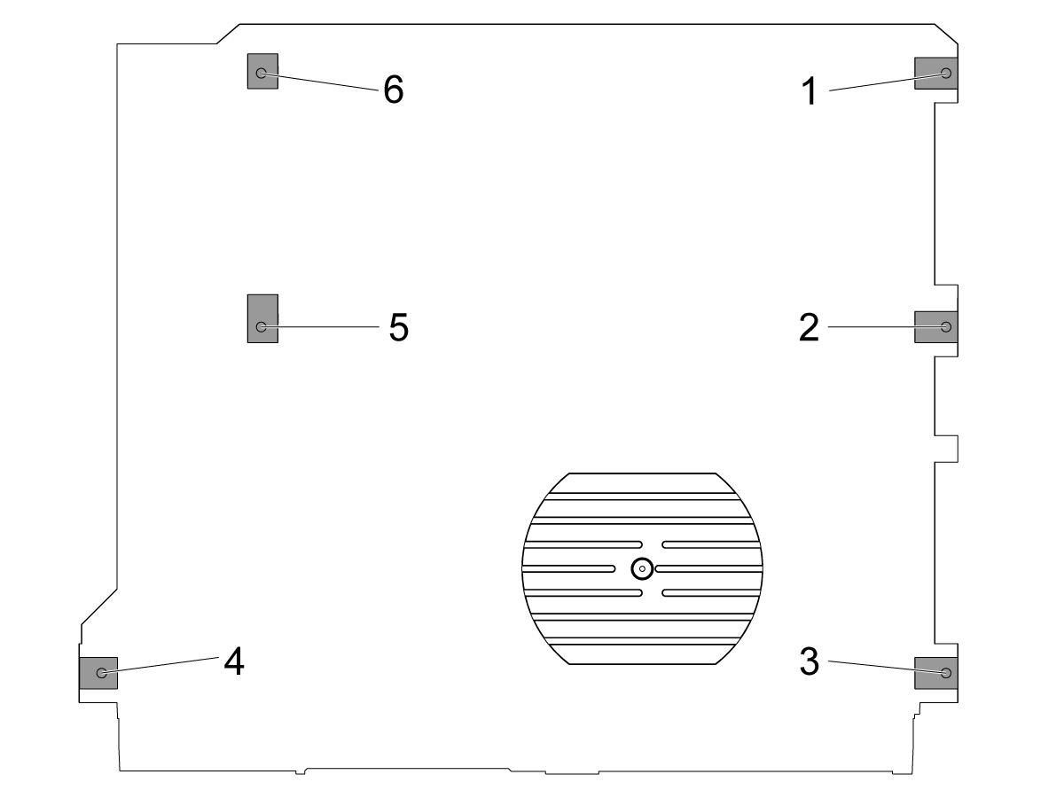
中央の水平調整ねじ[2および5]を緩めて、それらに荷重がかからないようにします。

床から3"(76.2mm)の高さで4隅の水平調整ねじ上に機械を設置します。

2

機械の大まかなレベリング:

水平調整ねじ#4を上に向けます。

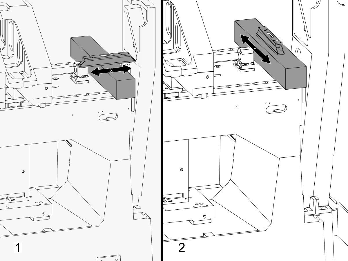
X軸ボールスクリューベアリングサポート付近のX軸リニアガイド全体にグラナイトを配置します。

X軸[1]に平行なグラナイトの上に機械工のレベルをセットアップします。

X軸で機械が水平になるまで、水平調整ねじ#6を調節します。

X軸[2]に垂直なグラナイトの上に機械工のレベルをセットアップします。

Y軸で機械が水平になるまで、水平調整ねじ#3を調節します。

水平調節パッドと接触するまで、水平調整ねじ#4を下方に回します。

3

X軸回転の調整:

T-2192とT-2181を組み立てます。

Y軸を移動の中央に移動します。

T-2192をスピンドルの側面に置きます。

T-2181のバブルが読み取り可能な範囲内にあることを確認してください。

そうでない場合は、T-2192を磁気ベースに固定しているボルトを緩め、必要に応じてアダプターを動かします。

X軸を左右にジョグして、X軸の回転を測定します。原点、中央、そして移動終了点で測定を行います。

原点での測定値と移動終了点の測定値にずれがなくなるまで、水平調整ねじ#4を調整します。

注記: T-2181のバブルは、バイアルの中央にある必要はありません。読み取り可能な範囲内にある必要があるだけです。

4

中央の水平調節ねじの設定:

水平調節パッドと接触するまで中央の水平調節ねじを下方に回し、続いてさらに45°回します。

X軸の回転を確認します。中央の水平調整ねじを調節して、X軸の回転を是正します。

X軸とY軸の整列

1

X軸の動きに平行なサドル面の整列:

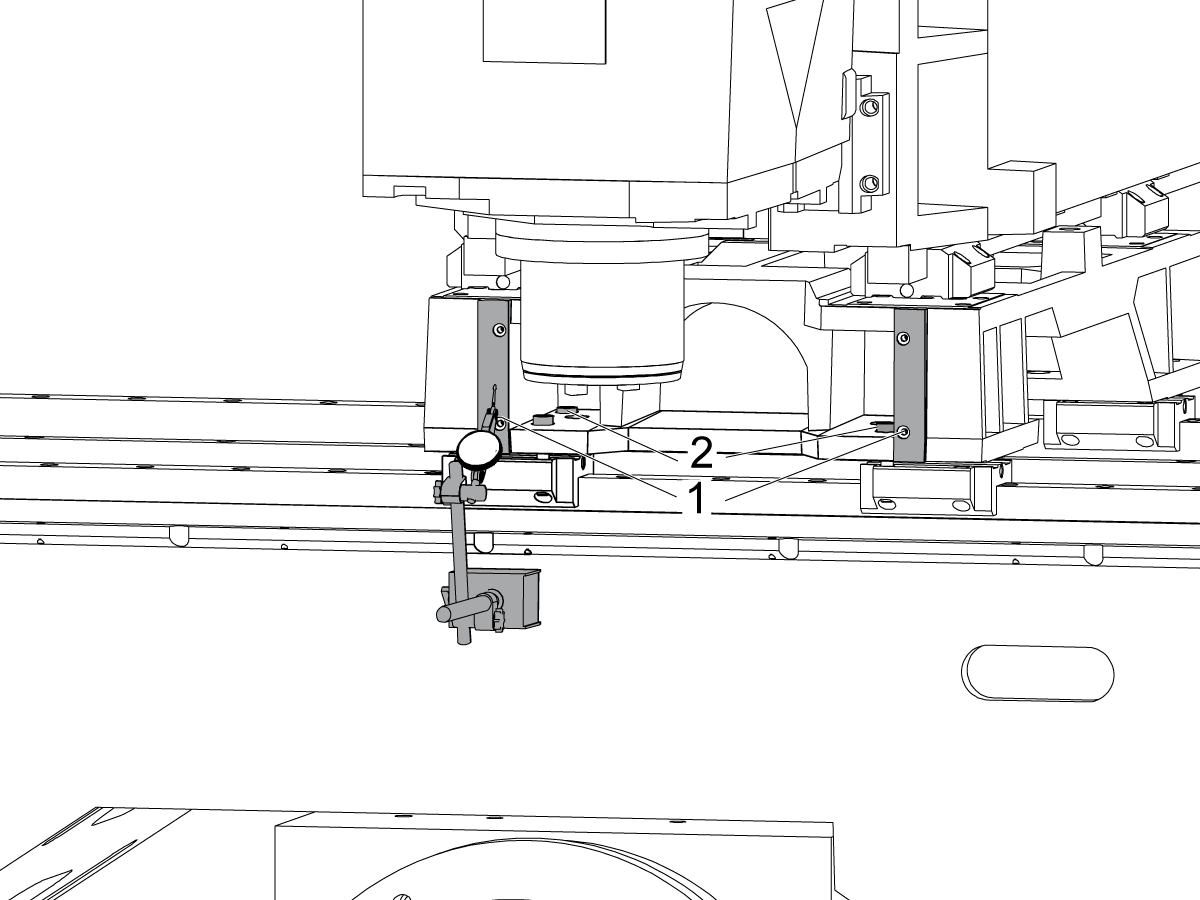
X軸をジョグして、サドル[1]の前面の加工面全体をスイープします。

サドルをX軸トラックに固定しているボルトを緩め[2]、必要に応じてX軸の動きに平行なサドルの面を0.001インチ以内に整列させます 。

ボルトにトルクをかけます。Haasファスナートルク仕様をご参照ください。

2

Y軸をX軸に対して垂直に整列:

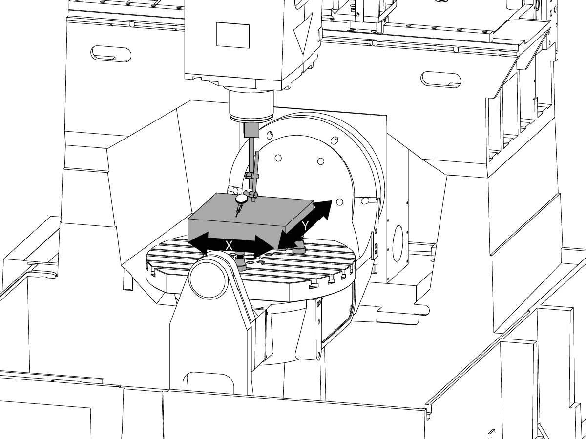
機械工ジャッキのC軸プラッタの左側にある直角測定用グラナイトをセットアップします。

直角測定用グラナイトの裏側をX軸に平行に設定します。NTE 0.0001"/10"

X軸とY軸に沿って、直角測定用グラナイトの上部をスイープします。

直角測定用グラナイトの上面がX-Y平面NTE 0.0005"に平行になるまで機械工ジャッキを調節します。

グラナイトの裏側がX軸に平行であることを確認します。NTE 0.0001"/10".

Y軸のトラックをサドルに固定しているボルトを緩め、Y軸をX軸に対して垂直になるように整列させます。NTE 0.0005"/10"

ボルトにトルクをかけます。Haasファスナートルク仕様をご参照ください。

ボルトを締め、Y軸がX軸NTE 0.0005"/10"に垂直であることを確認します。

Z軸とX-Y面の整列

1

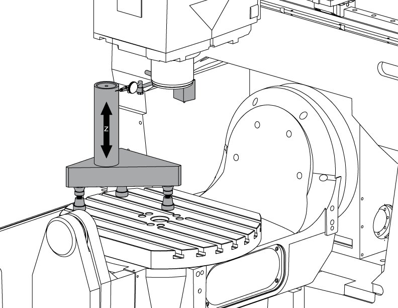
シリンダーをセットアップします。

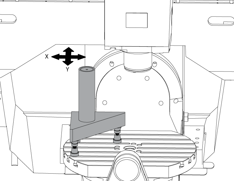
写真のようにトライストーンの上にシリンダーを置きます。

機械工ジャッキを回してシリンダーの上面をX-Y面NTE 0.0001"に平行に整列させます。

機械を次の位置までジョグします。

  • UMC-750はX -7.000"、Y -10.000"
  • UMC-750SSはX -10.000"、Y-10.000"

2

Z軸をX軸に対して垂直に整列:

Z軸トラックの上部コーナーボルトの1つをT-2193A *に交換し、それを中心にしてスピンドルヘッドを回転させます。

Z軸に沿ってシリンダーの側面を示します。

Z軸トラックをラムに固定しているボルトを緩めます。

スピンドルヘッドを左右に振ってZ軸をX軸NTE 0.0005"/10"に垂直に調整します。

ボルトにトルクをかけます。Haasファスナートルク仕様をご参照ください。

ボルトを締め、Z軸がX軸に垂直であることを確認します。

調整が終わったら、T-2193A*をボルトに交換します

*  :プリリブートシリーズでのみ使用されます。 

3

Z軸をY軸に対して垂直に整列:

Z軸に沿ってシリンダーの前面を示します。

Z軸トラックとラムの間にシムを挿入し、Z軸をY軸NTE 0.0005"/10"に垂直になるように整列させます。

注意:上の2つのトラックまたは下の2つのトラックのいずれかに同等のシムを挿入します。

ボルトにトルクをかけます。Haasファスナートルク仕様をご参照ください。

ボルトを締め、Z軸がY軸とX軸に垂直であることを確認します。

4

Y軸とZ軸のボールナットハウジングの整列とトルク:

ボールナットをハウジングに固定しているボルト、ならびにハウジングを鋳物に固定しているボルトを緩めます。

まずボールナットハウジングを鋳物に固定しているボルトを締め、次にボールナットをハウジングに固定しているボルトを緩めます。

ジョグロック機能を使用して、移動全量にわたって軸を前後に動かします。

注意:手動ハンドルや高速動作は使用しないでください。

ボルトにトルクをかけます。Haasファスナートルク仕様をご参照ください。

Y軸ナットハウジングには、ラムを機械の前方に向けてジョグすることにより、機械の後方でアクセスできます。

Z軸ナットハウジングには、スピンドルヘッドを完全に下にジョグすることにより、機械の前面からアクセスできます。

注意:Z軸ボールナットハウジングにアクセスするには、スピンドルモーターシュラウドを取り外す必要があります。

スピンドルをX-Y面に移動する

1

グラナイトのセットアップ:

写真に示されているように、機械工ジャッキとグラナイトをC軸プラッタの中央にセットアップします。

機械工ジャッキの高さをNTE 0.0001"に調節することにより、グラナイトの上面がX-Y面に平行になるように整列させます。

スピンドルをプラッタの中心に配置します。

2

スピンドルをX-Y面に移動:

スピンドルシャフトにインジケータを取り付けます。

90°回転するごとグラナイトの上で測定を行います。

スピンドルヘッドのベースプレートの6本のボルトを緩めます。

スピンドルヘッドの鋳物とベースプレートの間にシムを追加または除去して、スピンドルをX-Y面NTE 0.0005"/10"に移動します。

注意:厚さが異なるシム[1]を使用して、ベースプレートの角度を変えます。

スイープが仕様の範囲内である場合は、6本のボルトを締めます。Haasファスナートルク仕様をご参照ください。

ボルトを締め、スピンドルトラムを確認します。

B 軸の XYZ 軸への整列

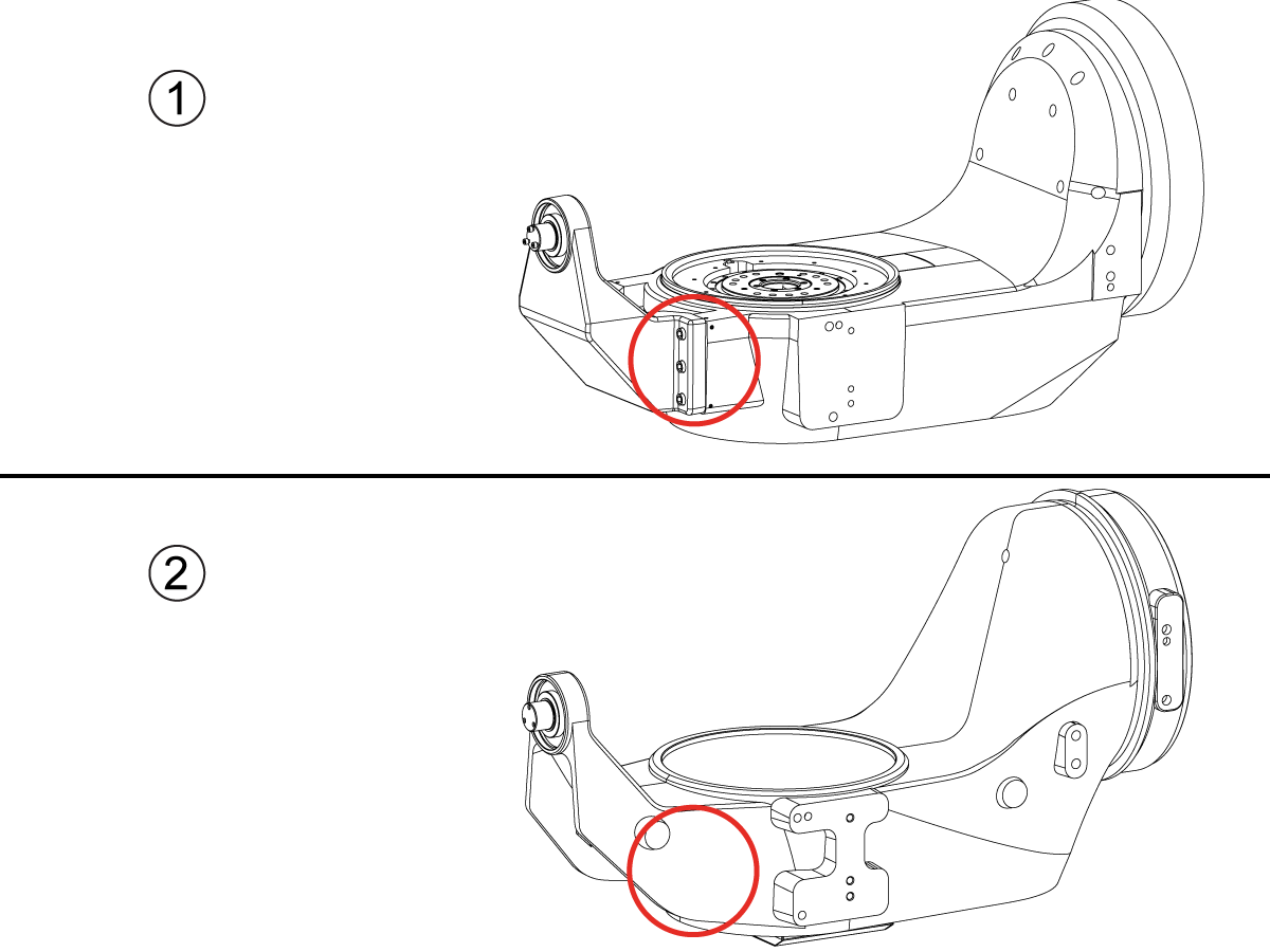
How to identify the Multi-Piece and the Unibody trunnion   

1) Multi-Piece trunnion:    UMC machines built approximetely before 11/2022 will have this configuration.

2) Unibody trunnion:    UMC machines built approximetely after 11/2022 will have this configuration.

1

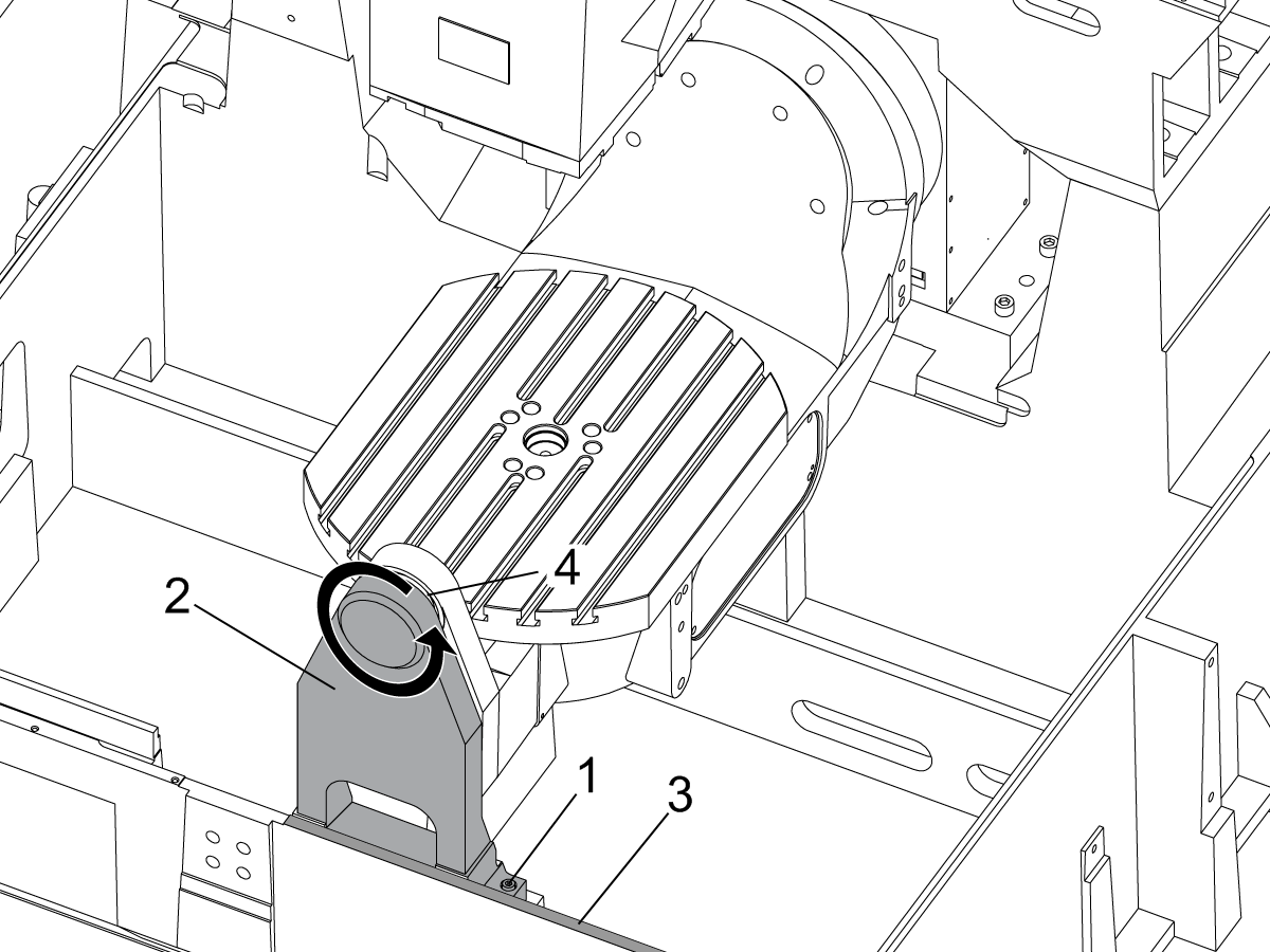
Remove the A-frame trunnion support:

Remove the bolts [1] that secure the A-frame trunnion support [2] to the base and take out the shims between A-frame support and the base.

Rotate the A-frame support [2] counter-clockwise to clear the edge of the base [3].

Pull the A-frame support off the bearings.

 Note: The A-frame support might vacuum lock on the bearings. Use the zip-tie to pry the seal [4] open.

 Caution: To lift the trunnion support, get the aid of another person. The support weighs 85 lbs (39 kg).

2

Measure the B- axis of rotation parallelism to the Y-Z plane:

For a machine with a Classic Haas Control, change Parameter 151:20 (B axis CHK TRAVL LIM) to 0.

For a machine with a Next Generation Control, change Parameter 6.021 (B axis CHK TRAVL LIM) to FALSE.

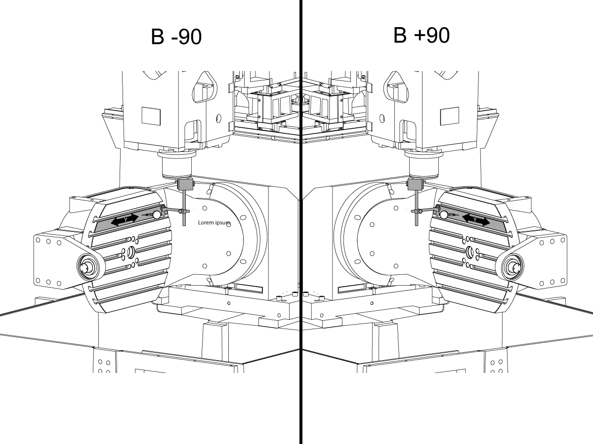
Measure the parallelism of the platter to the Y-Z plane with the B axis at 90° and then the B axis at -90° as shown in the picture.

Position the Y-Axis in the following starting position:

UMC-500: Y=0, Sweep 15”, 3rd T-Slot Land from the top.

UMC-750/1500-Duo: Y=-1.0, Sweep 18", 3rd T-Slot Land from the Top .

UMC-1250: Y=-1.0, Sweep 28", 3rd T-Slot Land from the Top.

UMC-500PP: Y=-4.0, Sweep 7".

UMC-750PP: Y=-2”, Sweep 15".

UMC-1000PP: Y=-4”, Sweep 15".

Compare the results at B 90° and B-90°. The results should be...

  • Symmetric against the Y-Z plane, positive or negative direction
  • Less than 0.0010"/20"

If the results are symmetric against Y-Z plane, and are less than 0.0010"/20 inches: Go to Step 5.

If the results are symmetric against Y-Z plane, but are more than 0.0010"/20 inches: Go to Step 4.

 Warning: If the results [3] are not symmetric against the Y-Z plane, the B axis rotary needs to be aligned: Go to Step 3.

3

Align the B axis of rotation parallel to the Y-Z plane:

Loosen the (6) bolts [1] that secure the B axis rotary to the base casting.

 Note: Keep the bolts sufficiently snug to control the adjustments.

Adjust the front and rear setscrews [2] until the measurements taken in Step 2 are symmetric against the Y-Z plane.

Torque the (6) bolts [1]. Refer to Haas Fastener Torque Specification.

Verify the measurements in Step 2 after the bolts have been torqued.

4

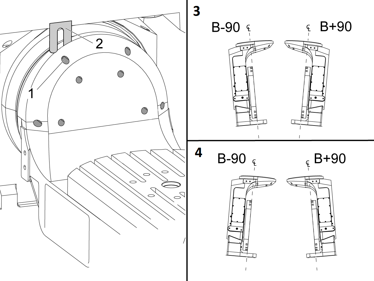
Align the C Axis of rotation perpendicular to the B Axis of rotation:

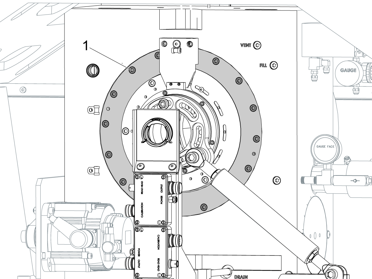
Remove the bottom C-Axis access cover.

Loosen the (12) bolts [1] that hold the C Axis body to the B Axis platter face.

Reach the bottom (4) bolts through the C Axis access port.

If the B Axis is symmetric in the positive direction [4], install horseshoe shims [2] of appropriate size behind the top (2) bolts.

If the B Axis is symmetric in the negative direction [5], install horseshoe shims [2] of appropriate size behind the bottom (2) bolts.

Torque the (12) bolts to 80 Ft-lbs (108 Nm).

Cut the excessive shim material off.

Verify the measurements in Step 2 after bolts are torqued.

5

Align the trunnion support shaft co-axial with the B Axis of rotation:

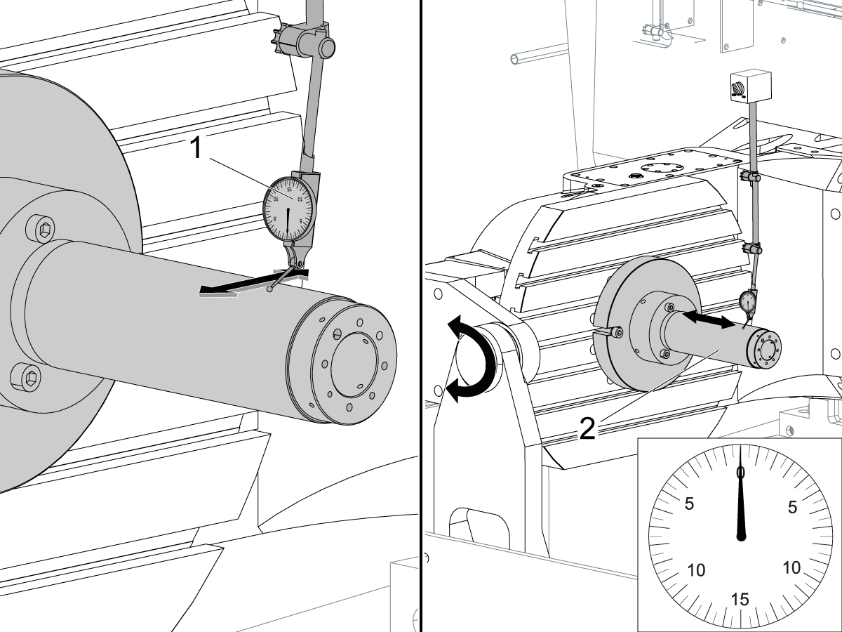
Setup (2) indicators on the outer race of the trunnion support bearing [2] as shown in the picture.

Mark the spot on the outer race where one of the indicator needles is contacting the surface.

After moving the B Axis to 90° or -90° you will align the marked spot with the needle again to exclude the bearing runout error from the measurements.

Take the readings when B is at 90° and B at -90°. Compare the readings. 

 Caution: The B axis brake needs to be clamped when taking the readings.

The deviation between the results when B is at 90° and at -90° needs to be less than 0.001" on each indicator.

 Note: The indicator on the side of the bearing will measure top to bottom alignment and the indicator on the top of the bearing will measure side to side alignment.

____

For models with a multi-piece trunnion

Loosen the (6) bolts [3] on the C Axis body support. Keep the bolts sufficiently snug to control adjustment.

Adjust the (8) set screws [4] until deviation between B at 90° and B at -90° is within 0.001".

Torque the (6) bolts [2] on the C Axis body support to 80 Ft-lbs (108 Nm).

Verify the alignment after the bolts have been torqued.

____

For models with a unibody trunnion

Jog rotary to B90. Set up an indicator on the highlighted surface as shown in the lower diagram .

Rotate B-axis 180 degrees (90 to -90).

Run out (NTE 0.010” TIR).

 Caution: If the measurement exceeds the tolerance then contact support.

6

Install and shim the A-frame trunnion support:

Move the B Axis to 90°.

Setup an indicator [1] against a machined surface of the C Axis body. Set the indicator to 0.

Use plastic zip ties [2] to pry the seal open while installing the A-frame support. This lets unwanted air and grease out of the assembly.

Install the A-frame trunnion support [3] over the bearings.

Remove the cable ties.

Turn the trunnion support clockwise until it is vertical.

 Note: The weight of the A-frame support will cause the trunnion to sag. The amount of sag is measured with the indicator that was previously setup on the side of the C Axis body.

____

For multi-piece trunnions

Adjust the shims [4] between the A-frame support and the base casting to remove the sag until indicator reads 0 again.

When the indicator reading is 0, torque the (4) bolts. Refer to Haas Fastener Torque Specification.

Verify the reading after bolts are torqued. Adjust the shims again if necessary until the indicator reads 0.

____

For models with unibody trunnion

Determine the amount of shim stock [4] needed to raise the Trunnion arm so the indicator reads 0.005".

The indicator [1] value will change once the support is torqued.

With indicator still in place:

  • Torque trunnion support bolts to appropriate values.
  • Check indicator to make sure it reads between the range of

Trunnion arm raised (0.005” to  0.010”).

 Note: For unibody trunnions, the shim location may also be used to correct the C-axis to X-Y plane perpendicularity instead of shimming the saddle trucks.

 Caution: Use equal amount of shims on each side of the A-frame support. Unequal shims will cause the A-frame support to pull the trunnion to the side.

Verify the B Axis of rotation alignment to the Y-Z plane (Step 2). Loosen the bolts and tap the A-frame support side to side if necessary to correct the B axis to Y-Z plane alignment.

7

Set C-axis perpendicular to X/Y plane:

Move the axes to

UMC-750's........X= -10.5" & Y=0."

UMC-1000's......X=-17.0" & Y=-0."

Zero an indicator [1], on a Ground Block [2], 1/2" off the edge at the rear of the platter (Mag-Base on Spindle), with C at 0 Degrees

Rotate C-Axis to 180°.

Move Y axis, and ground block, in Y Axis negative direction until you are 1/2" away from platter edge, and take the perpendicularity measurement

Adjust the shims until the average error is within 0.0005" end to end.

 Note: For unibody trunnions, the shim location under the bearing support may also be used to correct the C-axis to X-Y plane perpendicularity instead of shimming the saddle truck.

Caution: Shim either two front trucks or two rear trucks with the equal shim.

Note: Shim one truck at the time to maintain the X to Y squareness.

Verify the measurements after all bolts are torqued.

Verify the X to Y alignment in Step 2.

8

Set the tool change offsets:

B-axis tool change offset [1]

For Classic Haas Controls, change Parameter 213. 

For Next Generation Controls, go to: Settings>Rotary Tab>Highlight the rotary and press [INSERT], or change Parameter 6.078 (B TOOL CHANGE OFFSET) to set the trunnion (B Axis) parallel to the X Axis.

For models with multipiece trunnion

(NTE 0.001/10"; NTE 0.0020" overall)

For models with unibody trunnion

(NTE 0.0005/10"; NTE 0.0010" overall)

___

C-axis tool change offset [2]

For Classic Haas Controls change Parameter 523.

For Next Generation Control go to: Settings>Rotary Tab> Highlight the rotary and press [INSERT], or change Parameter 7.078 (C TOOL CHANGE OFFSET) to set the table T-slot (C Axis) parallel to the X Axis

For models with multipiece trunnion

(NTE 0.001/10"; NTE 0.0020" overall)

For models with unibody trunnion

(NTE 0.0005/10"; NTE 0.0010" overall)

9

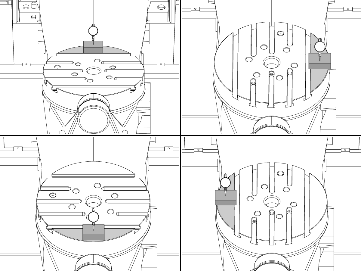
Check C-axis perpendicularity to X/Y plane:

Align the indicator centered over the C-axis bore with the Y-axis at -10.

Jog positive in the Y-axis and align the indicator over the center of the last section of the platter and make a mark at this spot with a washable marker.

Insert 1-2-3 block as shown and set the indicator to zero.

Remove the block and rotate the platter 90 degrees, following the marked spot with the indicator.

Insert block back between the indicator and platter. Note reading.

Repeat the previous two steps, taking readings with the platter at 180, 270 and 360 degrees.

Multi-piece trunnion:  (NTE 0.0005")

Unibody trunnion: (NTE 0.001")

10

Measure the intersection of the B and C axis:

Follow the linked instruction manual to complete this step.

B-Axis and C-Axis intersection Adjustment

11

Align the B-Axis brake disk:

 Note: Do not do this step if you are working on a SS machine.

Operate this code in MDI mode to unclamp the brake:

M11;

Loosen all of the brake disc bolts [1] and torque them to 5 Ft-lbs (7 Nm).

Operate this code in MDI mode to clamp the brake:

M10;

Wait 10 seconds.

Torque the bolts. Refer to Haas Fastener Torque Specifications.

パラメータの設定/工場出荷時の値に設定を戻す

CHCのパラメータ1314/NGCの設定254を工場出荷時の設定値に戻します。(値を変更した後、機械の電源を入れ直します。)

WIPSを整列させ校正します。直感型ワイヤレスプローブシステム(WIPS) - 校正

マシンロータリーゼロポイントを設定します。

  • UMC-750 - MRZP WIPSオフセット設定 - CHC
  • UMC-750 - MRZP WIPSオフセット設定 - NGC

次の検査レポートの全項目に記入します。

  • EA0420 UMC-500検査レポート
  • EA0373 UMC-750検査レポート
  • EA0418 UMC-1000検査レポート

検査レポートの写しを機械に残します。

B軸とC軸のアセンブリを交換した場合は、UMC-750 - B軸とC軸の交点 - 整列を実行します

Recently Viewed Items

You Have No Recently Viewed Items Yet

フィードバック
Haas Logo

Haas納入価格

この価格には、送料、輸出入関税、保険、およびお客様が購入者として同意されたフランスの宛先への配送中に発生するその他の費用が含まれます。Haas CNC製品の配送に他の必須費用を追加することはできません。

HAASに関する最新の情報と技術についてご紹介しています。

今すぐサインアップして下さい!   

HAAS TOOLINGは以下を受け入れます。

  • サービスおよびサポート
  • オーナー
  • サービスのリクエスト
  • オペレーターマニュアル
  • Haasの部品
  • ロータリーテーブルの修理リクエスト
  • 設置準備ガイド
  • ショッピングツール
  • 新しいHaasオンライン見積もり
  • 在庫状況
  • Haas製品の価格表
  • CNCAローン
  • Haasについて
  • アクセシビリティステートメント
  • DNSHステートメント
  • 輸出コンプライアンス
  • 採用情報
  • 認証と安全性
  • お問い合わせ
  • 会社沿革
  • ご利用規約
  • Haas Tooling ご利用規約
  • プライバシー
  • 保証
  • Haasコミュニティ
  • Haas 認定プログラム
  • Haasモータースポーツ
  • Gene Haas基金
  • HAAS技術トレーニングコミュニティ
  • イベント
  • 会話に参加する
  • Facebook
  • X
  • Flickr
  • YouTube
  • LinkedIn
  • Instagram
  • TikTok
© 2026 Haas Automation, Inc – CNC工作機械

This site is protected by reCAPTCHA and the Google Privacy Policy および Terms of Service apply.

2800 Sturgis Rd., Oxnard, CA 93030 / Toll Free: 800-331-6746
Phone: 805-278-1800 / Fax: 805-278-2255