My Haas Welcome,
!
Haas Tooling MyHaas/HaasConnect Sign In Register Haas Tooling MyHaas/HaasConnect Sign Out Welcome, My Machines Latest Activity My Quotes My Account My Users Sign Out
Find Your Distributor
  1. Select Language
    1. English
    2. Deutsch
    3. Español - ES
    4. Español - MX
    5. Français
    6. Italiano
    7. Português
    8. Český
    9. Dansk
    10. Nederlands
    11. Magyar
    12. Polski
    13. Svenska
    14. Türkçe
    15. 中文
    16. Suomi
    17. Norsk
    18. الإنجليزية
    19. български
    20. Hrvatski
    21. Ελληνικά
    22. Română
    23. Slovenský
    24. Slovenščina
    25. 한국어
    26. 日本語
    27. Українська
  • machines Main Menu
    • Vertical Mills
      Vertical Mills
      Vertical Mills View All
      • Vertical Mills
      • VF Series
      • Universal Machines
      • VR Series
      • VP-5 Prismatic
      • Pallet-Changing VMCs
      • Mini Mills
      • Mold Machines
      • High-Speed Drill Centers
      • Drill/Tap/ Mill Series
      • Toolroom Mills
      • Pocket Mill
      • Compact Mills
      • Gantry Series
      • SR Sheet Routers
      • Extra-Large VMC
      • Double-Column Mills
      • 3+2 Positioning Machines
    • Multi-Axis Solutions
      Multi-Axis Solutions
      Multi-Axis Solutions View All
      • Multi-Axis Solutions
      • Y-Axis Lathes
      • 5-Axis Mills
    • Lathes
      Lathes
      Lathes View All
      • Lathes
      • ST Series
      • Dual-Spindle
      • Box Way Series
      • Toolroom Lathes
      • Chucker Lathe
      • Pocket Lathe
      • Haas Bar Feeders
    • Horizontal Mills
      Horizontal Mills
      Horizontal Mills View All
      • Horizontal Mills
      • 50-Taper
      • 40-Taper
    • Rotaries & Indexers
      Rotaries & Indexers
      Rotaries & Indexers View All
      • Rotaries & Indexers
      • Rotary Tables
      • Indexers
      • 5-Axis Rotaries
      • Extra-Large Rotaries
    • Special Series
      Special Series
      Special Series View All
      • Special Series
      • EU_Series_Redirect
    • Automation Systems
      Automation Systems
      Automation Systems View All
      • Automation Systems
      • Mill Automation
      • Lathe Automation
      • Automatic Parts Loaders
      • Automation Models
    • Desktop Machines
      Desktop Machines
      Desktop Machines View All
      • Desktop Machines
      • Desktop Mill
      • Desktop Lathe
      • Control Simulator, Standard
      • Control Simulator, Premium
    • Shop Equipment
      Shop Equipment
      Shop Equipment View All
      • Shop Equipment
      • Knee Mill
      • Haas Manual Lathes
      • Haas Saws
    • Fabrication Machines
      Fabrication Machines
      Fabrication Machines View All
      • Fabrication Machines
      • Laser Cutting Machines
      • CNC Press Brakes
    • QUICK LINKS Special Series  Special Series 
      EU SERIES EU SERIES BUILD & PRICE | PRICE LIST BUILD & PRICE | PRICE LIST In-Stock Machines In-Stock Machines WHAT’S NEW WHAT’S NEW YOUR FIRST CNC YOUR FIRST CNC
      SHOPPING TOOLS
      • Build & Price a Haas
      • Price List
      • Available Inventory
      • CNCA Financing
      WANT TO TALK TO SOMEONE?

      A Haas Factory Outlet (HFO) can answer your questions, and walk you through your best options.

      CONTACT YOUR DISTRIBUTOR >
  • Options Main Menu
    • The Haas Control Value Option Packages
      Value Option Packages
      Value Option Packages View All
      • Value Option Packages
    • Product Image Spindles
      Spindles
      Spindles View All
      • Spindles
    • Product Image Tool Changers
      Tool Changers
      Tool Changers View All
      • Tool Changers
    • Product Image 4th- | 5th-Axis
      4th- | 5th-Axis
      4th- | 5th-Axis View All
      • 4th- | 5th-Axis
    • Product Image Turrets & Live Tooling
      Turrets & Live Tooling
      Turrets & Live Tooling View All
      • Turrets & Live Tooling
    • Product Image Probing
      Probing
      Probing View All
      • Probing
    • Haas Chip & Coolant Management Chip & Coolant Management
      Chip & Coolant Management
      Chip & Coolant Management View All
      • Chip & Coolant Management
    • The Haas Control The Haas Control
      The Haas Control
      The Haas Control View All
      • The Haas Control
    • Product Image Product Options
      Product Options
      Product Options View All
      • Product Options
    • Product Image Tooling & Fixturing
      Tooling & Fixturing
      Tooling & Fixturing View All
      • Tooling & Fixturing
    • Product Image Workholding
      Workholding
      Workholding View All
      • Workholding
    • Product Image 5-Axis Solutions
      5-Axis Solutions
      5-Axis Solutions View All
      • 5-Axis Solutions
      • 5 Easy Steps to 5-Axis
    • QUICK LINKS Special Series  Special Series 
      EU SERIES EU SERIES BUILD & PRICE | PRICE LIST BUILD & PRICE | PRICE LIST In-Stock Machines In-Stock Machines WHAT’S NEW WHAT’S NEW YOUR FIRST CNC YOUR FIRST CNC
      SHOPPING TOOLS
      • Build & Price a Haas
      • Price List
      • Available Inventory
      • CNCA Financing
      WANT TO TALK TO SOMEONE?

      A Haas Factory Outlet (HFO) can answer your questions, and walk you through your best options.

      CONTACT YOUR DISTRIBUTOR >
  • Why Haas Main Menu
      Discover the Haas Difference
    • Why Haas
    • MyHaas
    • Education Community
    • Industry 4.0
    • Haas Certification
    • Customer Testimonials
  • Service Main Menu
      Welcome to Haas Service
      SERVICE HOME Operator’s Manuals How-To Procedures Troubleshooting Guides Preventive Maintenance Haas Parts Haas Tooling Videos
  • Videos Main Menu
  • Main Menu
    • View All
    • View All
    • View All
    • View All
      • HTEC Curriculum Support
      • Haas Value Option Packages (VOP) Journey
    • View All
      • Haas 10 kg Cobot Package
      • Cobot Kits
      • DC-1 Drill Center
      • CNC Sales News
      • Do More With Your Haas
    • View All
    • View All
      • contact-us-test
      • 4 - AUTOMATION SYSTEMS
      • Carousel-V2
      • expert test
      • Demo_Day_Trident-test
      • Link Test
      • image-sale-tag-test
      • article-list-test
      • Haas 25 kg Robot Package
      • test-algolia-page
    • View All
    • View All
    • View All
    • View All
      • calc-test
    • View All
    • QUICK LINKS Special Series  Special Series 
      EU SERIES EU SERIES BUILD & PRICE | PRICE LIST BUILD & PRICE | PRICE LIST In-Stock Machines In-Stock Machines WHAT’S NEW WHAT’S NEW YOUR FIRST CNC YOUR FIRST CNC
      SHOPPING TOOLS
      • Build & Price a Haas
      • Price List
      • Available Inventory
      • CNCA Financing
      WANT TO TALK TO SOMEONE?

      A Haas Factory Outlet (HFO) can answer your questions, and walk you through your best options.

      CONTACT YOUR DISTRIBUTOR >
  • Haas Tooling Main Menu
  • Haas Service Parts Main Menu

My Haas Welcome,
!
Haas Tooling MyHaas/HaasConnect Sign In Register Haas Tooling MyHaas/HaasConnect Sign Out Welcome, My Machines Latest Activity My Quotes My Account My Users Sign Out
Find Your Distributor
  1. Select Language
    1. English
    2. Deutsch
    3. Español - ES
    4. Español - MX
    5. Français
    6. Italiano
    7. Português
    8. Český
    9. Dansk
    10. Nederlands
    11. Magyar
    12. Polski
    13. Svenska
    14. Türkçe
    15. 中文
    16. Suomi
    17. Norsk
    18. الإنجليزية
    19. български
    20. Hrvatski
    21. Ελληνικά
    22. Română
    23. Slovenský
    24. Slovenščina
    25. 한국어
    26. 日本語
    27. Українська
×

Search Results

Web Pages

Images

    • <
    • 1
    • >

HC-20KG-F - VF Side Load Installation - AD0958

Service Home How To Procedures HC-20KG-F - VF Side Load Installation - AD0958

HC-20KG-F - VF Side Load Installation - AD0958

- Jump to Section - Back to Top

4.4 VF Side Load Installation

Recently Updated Last updated: 03/26/2026

HC20KG-F VF Side Load Installation


AD0958

Revision B - 06/2026

Introduction

The Haas Cobot 20KG-F includes all the components needed to integrate the cobot with the Haas machine as an automatic parts loader.

The Cobot 20KG-F can be integrated on the following machines:

  • VF-1/SS/YT (Front Load)
  • VF-2/SS/YT & VM-2 (Front & Side Load)
  • VF-3/SS/YT & VM-3 (Front & Side Load)
  • VF-4/SS (Front & Side Load)
  • VF-5/SS/XT (Front & Side Load)
  • DC-1 (Side Load)
  • DC-2 (Front & Side Load)

In order for the cobot 20KG-F to be integrated with the Haas Machine, the machine must meet all of the requirements listed below. Refer to the links below for how to upgrade the machine to meet these requirements:

Machine Requirements:

  • Software Version 100.25.001.1300 or later
  • AD0413 - I/O PCB version 34-349xB or later
  • AD0669 - Dual Switch Autowindow or AD0513 - Auto Door
  • AD0533 - Remote Jog Handle TouchLCD (RJH-XL)

In addition to those requirements the machine may also require additional service kits to be ordered under the machine's serial number. The machine may need these kits depending on how the cobot was ordered/installed. 

There are 3 scenarios for how a cobot can be installed on the Haas Machine:

  1. Cobot option was ordered at the same time as the machine. Both the cobot and the machine are being installed together.
  2. Cobot option is ordered so that it can be installed on a previously installed machine.
  3. Cobot option was previously installed on a machine, but will now be moved to a different Haas machine.

Scenario 1 - Cobot and Machine are ordered and installed together

Component Part Number Description
NO ADDITIONAL PARTS NEED TO BE ORDERED WHEN COBOT AND MACHINE ARE ORDERED TOGETHER

Scenario 2 - Cobot being field installed on existing Haas Machine

Component Part Number Description
CHECK TO SEE IF HAAS MACHINE ALREADY HAS THESE FEATURES & PARAMETERS BEFORE ORDERING
Robot Feature Unlock Parameter 93-1001031 Kit activates the robot feature on the Haas machine. To check if you need this kit, go to the Features tab on the Haas Control and check if the Robot option is highlighted. This kit does not include any physical parts.
Load Type Safety Parameters 93-1000996 Side Automation Safety Parameters - Kit is needed when the cobot will be loading parts through the side window of the Haas machine. This kit does not include any physical parts and the autowindow option would need to be purchased and installed separately.

Scenario 3 - Cobot is being transferred from one machine to a different Haas Machine

Component Part Number Description
Cobot Integration Kit 93-1001280 Integration Kit Side Load Fanuc - Kit is needed to install parts on the Haas machine to interface with the cobot. This includes the interface box, door switches, etc... as well as the Robot Unlock Feature parameter. This kit only needs to be purchased when transferring a cobot to a new Haas machine since these parts are normally included when a cobot is ordered. 
Load Type Safety Parameters 93-1000996 Side Automation Safety Parameters - Kit is needed when the cobot will be loading parts through the side window of the Haas machine. This kit does not include any physical parts and the autowindow option would need to be purchased and installed separately.
Safety Device 08-1899 Multi-Sided Light Curtain Kit - Kit is needed if the safety device is NOT going to be transferred from the first machine and the second Haas machine needs it's own safety device. This kit makes a 4-sided protective barrier.
OR  
08-1948 5-Sided Light Curtain Kit - Kit is needed when the safety device is NOT going to be transferred from the first machine machine and the second Haas machine needs it's own safety device. This kit makes a 5-sided protective barrier.
OR  
08-1987 Laser Area Scanner Kit - Kit is needed when the safety device is NOT going to be transferred from the first machine machine and the second Haas machine needs it's own safety device. This area scanner has a sensing distance of 4meters.

Cobot Unpacking

There are several components packaged with the cobot:

  1. Cobot Arm (Mechanical Unit Box) [1]
  2. Cobot Control (Controller Box) [2]
  3. Control Box to Arm Signal Cable (Accessories Box)
  4. Teach Pendent Tablet and Cable (Accessories Box)
  5. Cobot Mounting Hardware

 Important: Verify you received these components during unboxing and save all documents provided with the cobot. These documents should be stored where they can be found at any point over the life of the cobot.

Below are the components that need to be installed in order to integrate the cobot to the Haas Machine. These will be delivered in additional packaging:

  1. Mounting Pedestal [3]
  2. Parts Table and Template [4] 
  3. Part Flip Station [5]
  4. Electrical Interface Kit [6]
  5. Safety Device [7]
  6. Gripper Assembly [8]
  7. Pneumatic Supply Assembly [9]
  8. Permanent Anchoring Hardware

 Note: Other components are included with a cobot such as cables and anchoring provisions. Refer to HBC for a complete list of items that were ordered.

Install Cobot and Control Box

1

Place the cobot pedestal [1] in position.

Use a lifting strap to position the cobot arm [2] onto the pedestal.

Orient the cobot so that the electrical connector coming out of the base of the cobot [3] is pointed to the left as shown in the image.

 Note: The electrical connector indicates the travel limit for Joint 1. Having it oriented correctly will make setting up a job much easier.

 Note: The pedestal has many different mounting holes to accommodate the different size cobots. The HC20KG-F should be mounted in the hole pattern shown in red [5]. 

Fasten the arm to the pedestal using the M8 SHCS and washers [4] provided in the cobot packaging.

Torque the mounting SHCS according to RD0026 - Haas Fastener Torque Specification

2

Place the cobot control box [1] next to the pedestal [2].

The cobot signal cable needs to be connected from the control box to the arm. Connect the male end of the cable to the control box port [3] and connect the female end of the cable to the base of the cobot arm [4].

Warning: Make sure that the connectors are oriented properly to avoid damaging any pins on the connector. Verify that both ends of the cable are securely connected before powering on.

3

The ground cable also needs to be connected between the cobot arm base [1] and the cobot control box [2].

The grounding locations are shown in the image. The control box ground terminal is located above the cobot signal cable that was installed in the previous step.

Note: The larger eyelet ring connector should be connected to the control box terminal [2].

4

Connect the teach pendent tablet to the control box.

Connect the male end of the teach pendent cable [1] to the control box terminal on the right side.

Connect the other end of the teach pendent cable to the teach pendent holster [2].

Once these connections are made and the teach pendent, control box, and cobot arm are all installed, the cobot control box can be connected to incoming power. Incoming power for the HC20KG is supplied from the Haas Machine. Continue to the Electrical Installation section below for more details.

5

Updated

Take the Haas spec plate [1] and place it on top of the cobot control box [2] as shown in the image.

Use double sided tape to secure the spec plate in position.

The spec plate includes:

  • Haas Serial Number
  • Model Type

Electrical Installation

 DANGER: Working with the electrical services required for CNC machines is extremely hazardous and can result in serious injury or death.

Before connecting line wires to the CNC:

  • Turn off all power to the machine at the source.
  • Perform a Lockout-Tagout (LOTO) procedure to ensure the power remains off during service.
  • Verify that power has been disconnected by using an AC voltage detector on all incoming lines.

If you are uncertain about how to safely disconnect power or perform LOTO procedures:

  • Do not proceed.
  • Contact qualified personnel or obtain appropriate assistance before continuing.

Failure to follow these precautions may result in electrical shock, equipment damage, or fatal injury.

 Danger: Before beginning any work inside the control cabinet, verify that the High Voltage indicator light on the 320V Power Supply / Vector Drive has been off for a minimum of five (5) minutes. This waiting period ensures that residual voltage has dissipated and reduces the risk of electric shock.

Certain service procedures involve high-risk electrical components and may pose serious injury or fatality hazards. Technicians must not attempt any procedure unless they have a complete understanding of the steps involved and the associated risks.

If there is any uncertainty regarding a procedure, contact your Haas Factory Outlet (HFO) to arrange for a qualified service technician.

1

Perform the following steps to connect the cobot to the Haas machine.

Main Transformer

  • Connect cable [1] P/N 33-8570 to Main Transformer follow the labels to terminals 77 and 78,  connect the ground loop terminal to chassis.

I/O PCB and Maincon PCB

Cable P/N 33-8561C has multiple connections:

  • Connect the E-STOP terminal block connections  to SIO PCB TB-1B (see diagram) [2].
  • Verify the jumper is installed on the SIO PCB at JP1
  • Connect the Setup mode terminal block connections to SIO PCB TB-3B (see diagram) [2].
  • Connect the cable labeled P1 SIO to the SIO PCB at P1 [3].
  • Connect the RJ-45 cable [4] to Ethernet to USB adapter [5] (P/N 33-0636).  Connect the USB connector end to the Maincon PCB J8 top port (see diagram). Add a ferrite filter 64-1252 to the USB adapter.
  • Mount the 24VDC Power Supply [11] to the left side of the control cabinet and plug into connector labeled 24V PS on cable 33-8561C. Connect cable 33-1910A [10] to the 24VDC Power Supply [11] and plug into P3 on the PSUP PCB.
  • Plug the User Relays into K9 and K10. (see diagram) [12].

Note: If the machine does not have a Regen Vector Drive, do not plug anything into the connector FILTER OV FAULT.

Robot Electrical Box to Robot Control

  • Connect the Robot Control Signal Cables [7] P/N 33-1542 to the Robot Electrical Interface Box. Add a ferrite filter 64-1252 to the RJ-45 cable. See the next step for more detail on where to connect the signal cable inside the Robot Control Box.

IMPORTANT: When connecting the Robot Control Signal Cable [7], make sure to line up the M12 connector female notch with the M12 connector male key to prevent any misalignment that could result in damaged pins. 

Robot Power

  • Connect the 220VAC power cable [8] 33-1552 to the Robot Electrical Interface Box. Connect the other end to the Robot Control Box [6].

Robot Safety Device 

  • Connect the light curtain receiver cable [9] from the electrical interface box to the light curtain receiver. 
  • Connect the light curtain emitter to the Robot Interface Box using the emitter cable [13].

2

 Warning: If the Haas Machine is powered ON, disconnect the 220VAC power cable from the electrical interface box. 

Place the electrical interface box on the enclosure of the Haas Machine.

Feed the other end of the robot signal cable 33-1542 coming from the front of the interface box and the gripper solenoid cable 33-1548 through the right side of the cobot control box [1].

Open the control box and connect the RJ-45 cable to port CD38A [2] located in the upper right corner of the PCB on the back wall of the control box.

Pull enough slack of the robot signal and gripper solenoid cable so that they can be connected to the IO/Safety PCB [3] located on the inside of the control box door.

See the next step for where to connect the robot signal and gripper cable to the IO/Safety PCB.

3

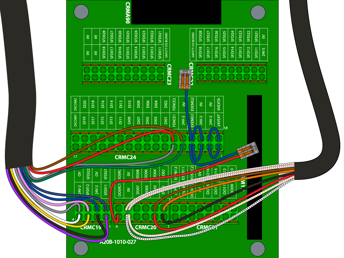
The cobot control box will come with jumpers on the safety/IO PCB. These jumpers will have to be moved in order to connect the robot signal cable to the safety/IO PCB.

The jumpers will be connecting the following pins on CRMC24:

  • 24VEXT to 24V-2 (p1 to p2) [1]
  • 0VEXTA to 0V (p18 to p19) [2]
  • EXEMG1 to 24V-2 to FENCE1 (p4 to p5 to p6) [3]
  • EXEMG2 to 0V to FENCE2 (p21 to p22 to p23) [4]

 Note: All terminal locations are labeled on the PCB as shown in the image.

4

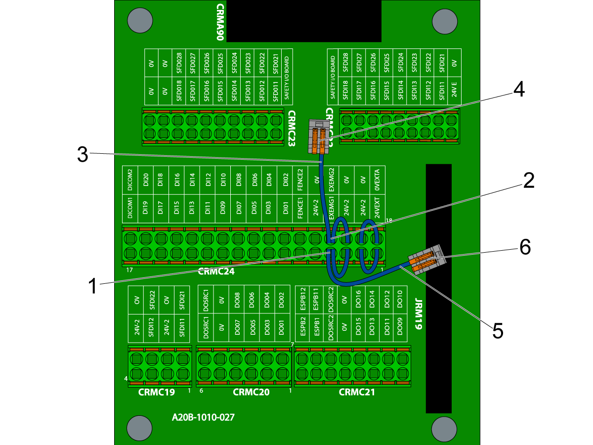
Disconnect the jumper from {EXEMG1 to 24V-2 to FENCE1} and the jumper from {EXEMG1 to 24V-2 to FENCE1}.

Move the jumpers so that they are connected in the following way on the CRMC24 terminal:

  • 24V-2 to EXEMG1 and leave FENCE1 disconnected (p3 to p4 and FENCE1 disconnected) [1]
  • 0V to EXEMG2 and leave FENCE2 disconnected (p20 to p21 and FENCE2 disconnected) [2]

Use the wago connectors provided in the integration kit. Connect the FENCE2 pin of the jumper [3] to one wago connector [4]. Then connect the FENCE1 pin of the jumper [5] to the other wago connector [6].

5

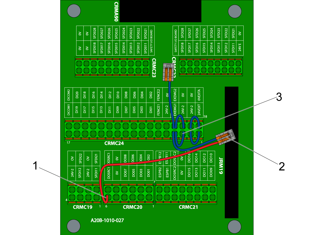
Connect the red jumper wire 33-1553 to the safety/IO PCB.

Connect one end of the red jumper wire to the DOSRC1 (p6) [1] on CRMC20.

Connect the other end of the red jumper wire to the wago connector [2]. Use the wago connector that is connected to the blue wire labeled FENCE1.

 Note: The label on 33-1553 is labeled pin 3. Use the wago connector since the other end of the blue FENCE1 wire is connected to pin 3 [3].

6

Route the robot signal cable to the safety/IO PCB. Connect the cable to the safety/IO PCB as shown in the image:

Connections to CRMC24

  • GREEN wire to 24V-2 (p5)
  • GREY wire to FENCE1 (p6)
  • BROWN wire to 0V (p22)
  • RED wire to FENCE2 (p23)

Connections to CRMC19

  • VIOLET wire to SFDI11 (p1)
  • BLACK wire to 24V-2 (p2)
  • YELLOW wire to SFDI12 (p3)
  • WHITE wire to 24V-2 (p4)
  • BLUE/RED wire to SFDI21 (p5)
  • BLUE wire to 0V (p6)
  • PINK wire to SFDI22 (p7)
  • GREY/PINK wire to 0V (p8)

7

Route the dual gripper solenoid power cable 33-1548 [1] to the safety/IO PCB. Make the following connections:

Connections to CRMC20

  • BLACK to DO01 (p1)
  • RED to DO03 (p2)
  • WHITE/BLACK & WHITE/ORANGE to 0V (p5)
  • ORANGE to DO02 (p7)
  • BROWN to DO04 (P8)
  • WHITE/BROWN & WHITE/RED to 0V (p11)

8

Once everything is connected inside the control box, connect the 220VAC power cable coming from the interface box on the Haas machine.

The power cable is connected to the 4 pin connector on the right side of the control box [1].

 Note: The connector is keyed. Make sure you have the connector oriented correctly before trying to connect to the control box. 

Secure the connector by tightening the threaded collar.

Safety Device Installation

IMPORTANT: DO NOT OPERATE THE ROBOT UNTIL YOU HAVE PROPERLY CONFIGURED AND TESTED THE OPERATION OF THE SAFETY DEVICE.

The Haas Cobot-F Package comes with a safety device that must be enabled to integrate the cobot to the machine. 

The standard option for the safety device is a 3 sided light curtain barrier. This Can be upgraded to a 5 sided light curtain barrier or a 4meter area scanner option.

Refer to the sales order of the machine for which safety device was selected. There are links below for how to install the light curtains and area scanner.

Light Curtain:

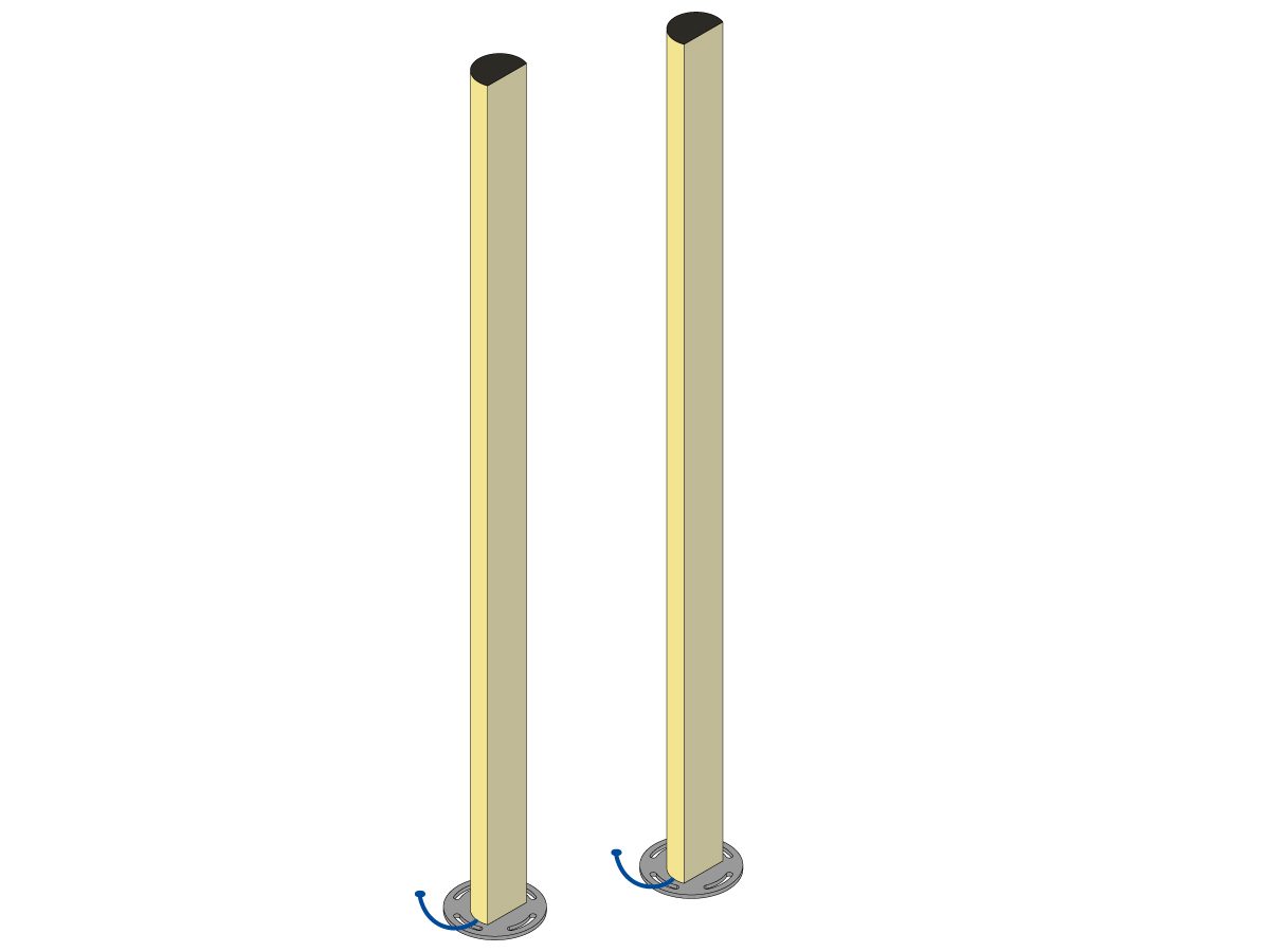
Cobot packages come with the light curtain emitter and receiver as the default safety device. Follow the procedure below for light curtain installation: 

Light Curtain Installation

 Note: The light curtains also come with mounting plates. These mounting plates should be anchored to prevent the light curtains from being misaligned. 

Light Curtain Anchoring

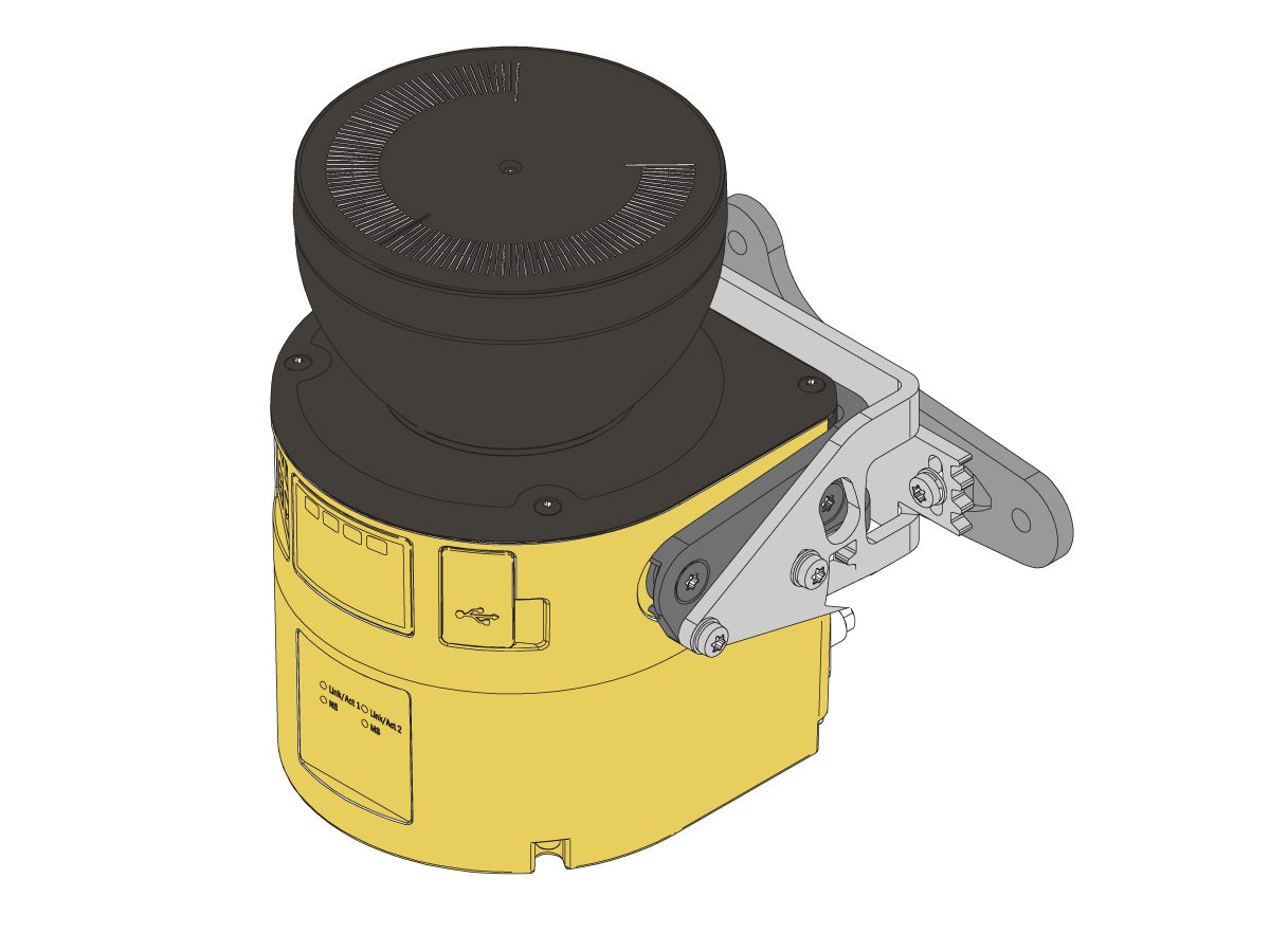
Area Scanner:

If the machine came equipped with the area scanner option, the area scanner needs to be installed and configured to the space. Follow the procedure below for installation: 

Area Scanner Installation

First Power Up

There are several parts to this section:

  1. Power ON the cobot and verifying that the cobot can be utilized from the teach pendent without any alarms.
  2. Take a full system and image backup on the cobot control box 
  3. Configure the Haas control to integrate with the cobot.
  4. Connect to the cobot from the Haas machine.
  5. Activate the cobot using HBC.
  6. Verify that the cobot can be utilized from the Haas control.
  7. Take an error report on the Haas machine

These should be done in order. This will help diagnose whether the problem is on the Haas machine side or the cobot control side if any issues are seen.

1

Power ON the Haas Machine. Once the machine is booted up, turn the main breaker on the cobot control box [1] to the ON position.

Power on the teach pendent tablet by pressing the button on the side [2] as shown in the image.

Once the teach pendent powers on, swipe up from the bottom to unlock the tablet and get to the home page as shown in the image [3].

2

Swipe up to view the list of apps installed on the teach pendent.

Press on the Tablet TP app icon [1] to open the teach pendent application.

If the control box was just powered on then you will see the loading screen [2] indicating that the control box is still booting up. 

 Note: It may take a 1-2 minutes for the control box to fully boot up.

3

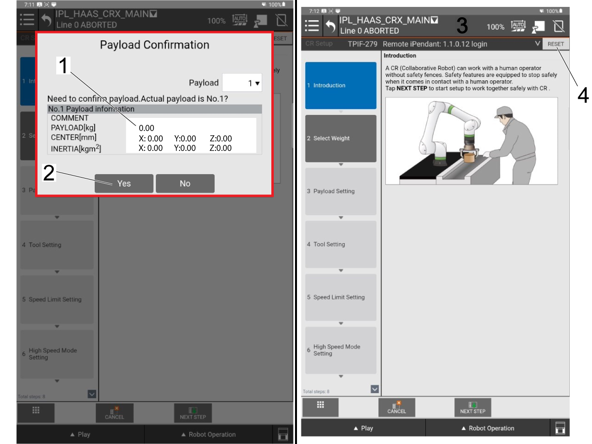
Once the application boots up there will be a Payload Confirmation window that pops up.

The cobot will list the payload, center of mass, and inertia that is detected. Since the cobot is not yet connected to the Haas machine and there is no grippers installed, there should be no payload detected.

 Note: Small deviations in payload on the payload confirmation pop up will not impact the cobot. If you notice a difference in payload on this screen still continue.

Check that the listed payload seems accurate and then press [Yes] [2] to continue.

Once the payload confirmation is successful you will be taken to the main menu. If there are any alarms present they will show up near the top of the screen [3]

Press [Reset] [4] to clear any alarms. 

 Note: Refer to section 8.1 Cobot-F Troubleshooting for more details on any alarms that you can't clear.

4

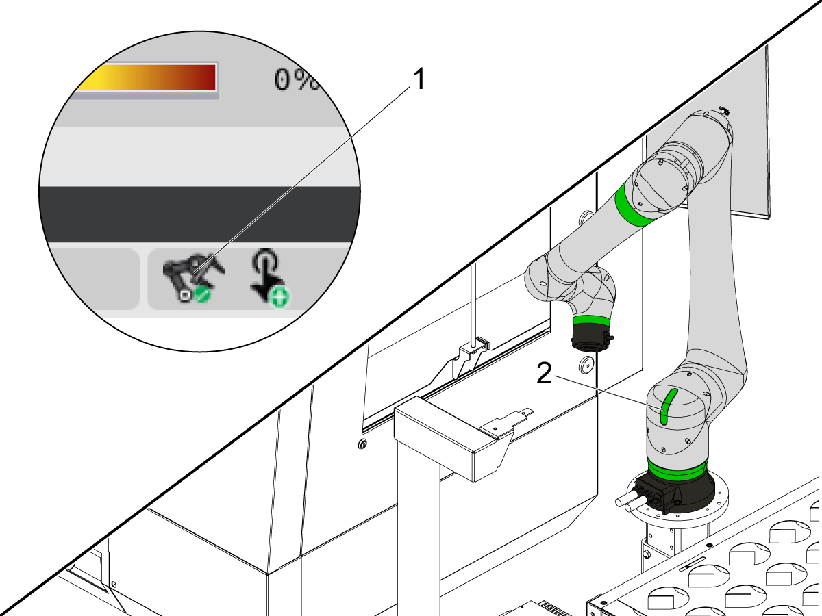
When all alarms are cleared the indicator light on joint 1 [1] of the cobot arm will turn green as shown in the image.

Press the Robot Operation button at the bottom of the screen [2].

From there click the jog tab and use the sliders [4] to ensure that the cobot can jog.

 Note: Keep the override low so you don't get big movements when jogging. The image shows the override at 10%.

5

Take a full system and image backup from the cobot control box.

Insert a usb into the UD1 port on the right side of the control box [1]. (Next to the pendent signal cable.

Follow the video for how to take the system and image backup.

  1. Press on the hamburger menu on the upper left corner.
  2. Navigate to the File Backup option under the Utility submenu.
  3. Select the Front Panel USB (UD1) option and press next step at the bottom.
  4. Select Create Directory and then confirm the directory name you wish to use.
  5. Press next step at the bottom. Enable the teach pendent by clicking the TP button on the top right of the screen. Then select the Full System and Image Backup option.
  6. Wait for the files to copy and for the SYST-360 - Please cycle power alarm to generate.
  7. Press the hamburger menu and go to the Cycle Power option. Select Cold Start.
  8. Wait until you get the SYST-213 - User Cycle Power warning. Then power OFF the control box circuit breaker and wait 15 seconds before turning it back ON.

Wait until the cobot boots back up and all alarms are reset before continuing to the next step.

 IMPORTANT: Make sure to change the teach pendent back to Disabled mode [1]. TP disabled mode is when there is a line through the rectangle as shown in the image.

6

Move to the Haas control pendent to configure the Haas machine to integrate with the cobot.

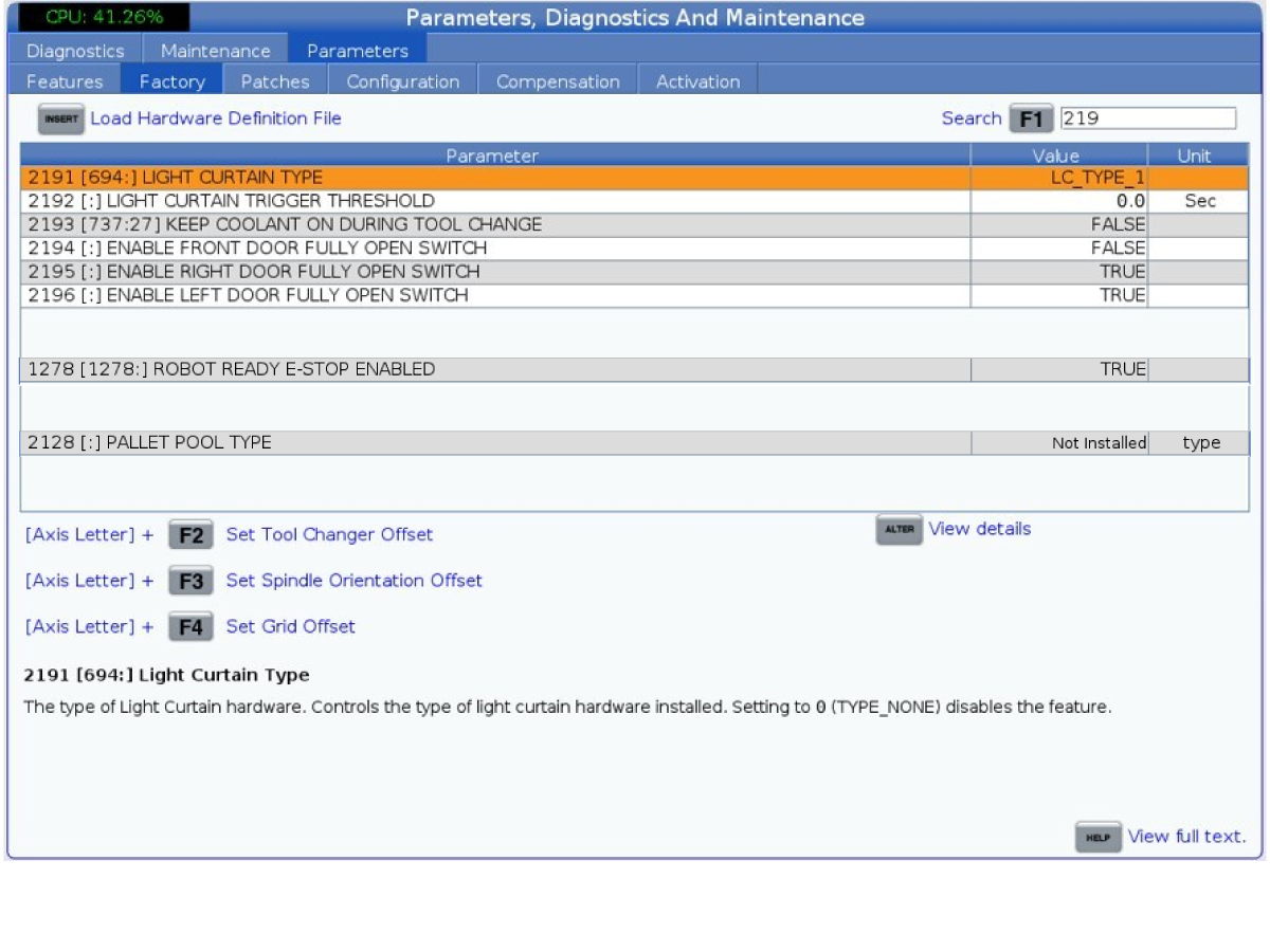
Press [DIAGNOSTICS] and navigate to the Factory tab and press [E-STOP]. Verify that the below parameters are set correctly.

  • 1278 [1278:] Robot Ready E-Stop Enabled to TRUE
  • 2191 [694:] LIGHT CUTAIN TYPE to LC_TYPE_1
  • 2195 [:] Enable Right Door Fully Open Switch to TRUE
  • 2196 [:] Enable Left Door Fully Open Switch to TRUE
  • 2192 [:] Light Curtain Trigger Threshold to 0
  • 2128 [:] Pallet Pool Type to 0

 Note: These parameters are needed to enable the light curtains and the door fully open confirmation switches.

7

Press the [SETTING] and verify that the below settings are set correctly:

  • 372 Parts Loader Type to 3: Robot
  • 375 APL Gripper Type to None
  • 376 Light Curtain Enabled to On

 Note: You must have the light curtains enabled to integrate the cobot with the Haas machine. Without setting 376 enabled, the control will display a message asking you to activate the light curtain.

Once these settings are set, you can now view the APL and Robot tabs inside the Current Commands menu.

8

Press [CURRENT COMMANDS] and navigate to the Devices -> Robot -> Setup menu.

Press [E-STOP] on the Haas pendent.

Then press [F1] [1] to establish a connection to the cobot.

Wait for a few seconds for the Haas machine to connect to the cobot.

 Note: If this is the first time the Haas machine has connected to the cobot you will see the Activation popup on the Haas pendent.

If the cobot already has been activated, then you will know that you are connected based off the robot icon on the lower right corner of the Haas icon. A green icon indicates a connection. A red icon indicates the cobot isn't currently connected [2].

9

If you need to activate the cobot, then you will get the popup similar to the image.

The popup will have the following displayed:

  1. Software Version of the Haas Machine
  2. MAC Address of the cobot connected [1]
  3. Generated Code

You will need to locate and enter the following to successfully activate the cobot:

  1. F Number [2]
  2. Unlock Code [3]

Note: The unlock code can only be obtained through the Robot Activation transaction on HBC.

10

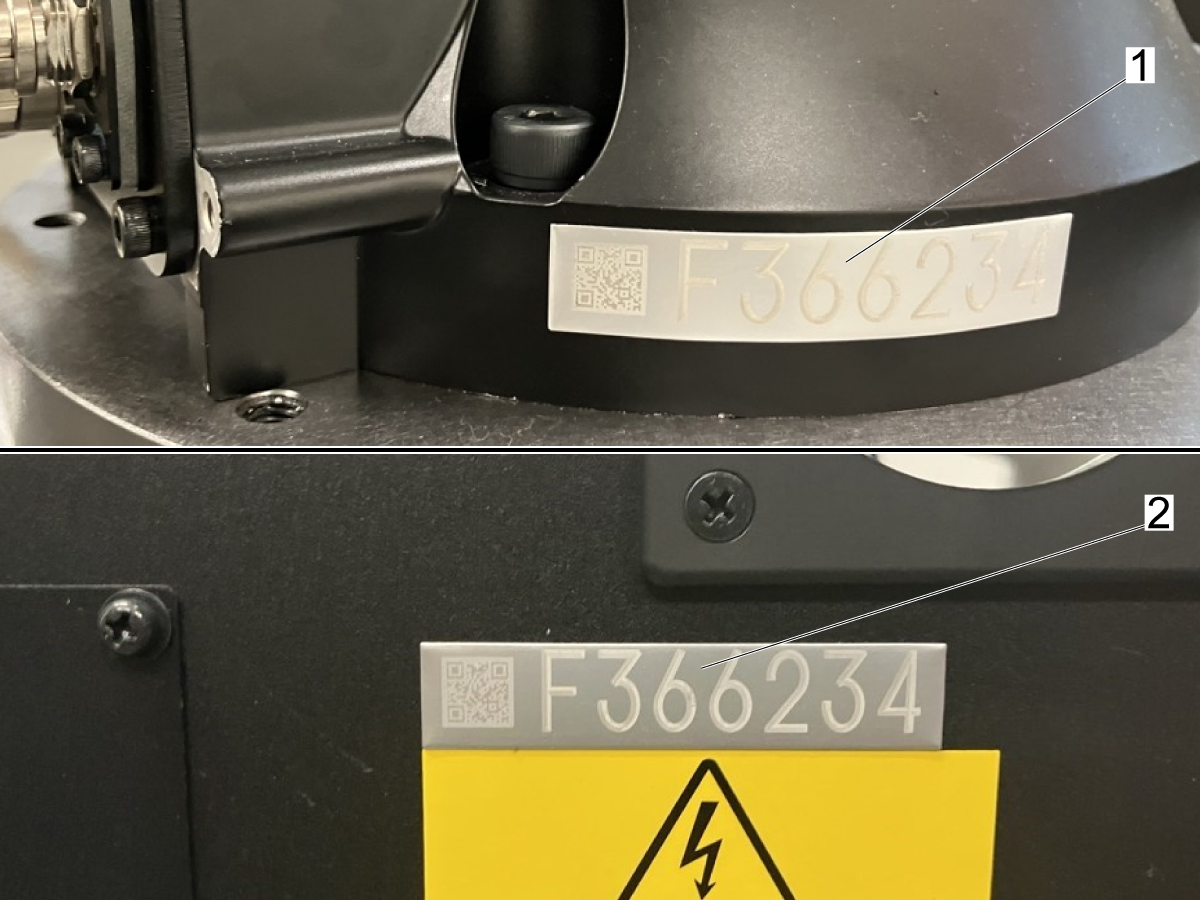
Finding Cobot F Number:

There are 2 ways to locate the F number on a Cobot:

  1. The placard on the base of the cobot below Joint-1 [1]
  2. The placard on the front door of the control box above the spec plate [2]

11

Getting Unlock Code through HBC:

The unlock code can only be obtained through HBC by a Haas Certified Technician.

On HBC press on the Service tab [1] and then find the Robot Activation transaction [2] on the left side menu.

Complete all the fields on the various steps in the activation process. 

 Note: You will need information included on the activation popup as well as the serial numbers of both the Haas machine, Cobot package, and the F-number to obtain the Unlock code.

Enter the F-Number [3] and the Unlock Code [4] on the popup in order to activate the cobot.

12

After activation is successful, press [F1] to connect to the cobot again if needed.

Wait for the robot icon to turn yellow or green [1]. Then release [E-STOP] and clear the alarms by pressing [RESET].

Look at the indicator light on Joint-1 on the cobot arm [2] and verify that it is green as well.

Configure Grippers and Payload

1

Start by setting the Number of Grippers field [1] to either 1 (for single gripper) or 2 (for dual gripper).

Configure the gripper Clamp/Unclamp outputs as listed below.

For the Raw Gripper [2] (Gripper 1):

  • Clamp Output = 2 
  • Unclamp Output  = 1
  • Clamp Delay = 0.0
  • Clamp Type = Outside

For the Finish Gripper [3] (Gripper 2):

  • Clamp Output = 4
  • Unclamp Output = 3
  • Clamp Delay = 0.0
  • Clamp Type = Outside

 Note: These fields can be reconfigured depending on the application. This is just to confirm that the grippers work as intended.

2

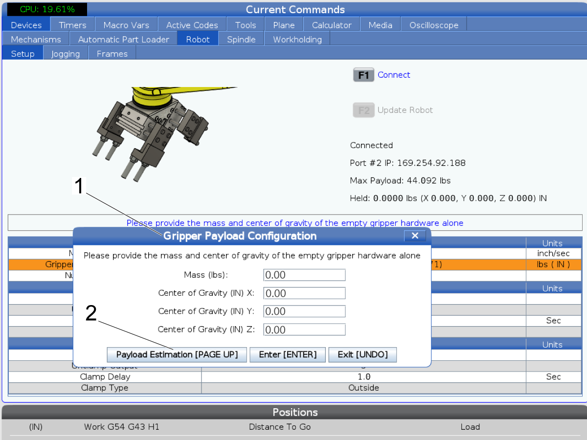
The Gripper Net Mass field needs to be completed. This can be completed by going through the payload estimation process detailed below.

Press [ENTER] to bring up the Mass and Center of Gravity popup [1].

Press [PAGE UP] to start the Payload Estimation process.

 Note: You may see a Payload Confirmation Required popup when you try to set the payload. Press [Y] if the payloads are correct [2]. They should be zero if this is the first time setting payloads.

Note: When starting the payload estimation for the grippers, make sure you start with nothing attached to the end of joint-6 on the arm.

3

Follow the instructions on the popup:

Step 1 - Pre-Position: Make sure that the cobot is in a position so that it can move joints 5 and 6 freely without contacting anything.

If needed, use the RJH-XL to jog the cobot to an open area.

4

Step 2 - Clamp/Unclamp Grippers: Follow the prompt to unclamp the grippers assembly. 

Even though there are no grippers on the arm, you need to press [F2] [2] if it says that the action is Pending [1]. It will show Completed when the action is done.

Once the action is completed press the right arrow [3] to continue to step 3.

5

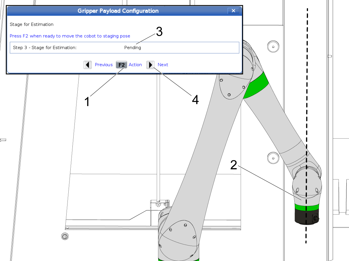
Step 3 - Stage For Estimation: During this step, the cobot will automatically move to position the end of Joint-6 to point straight down like it is hanging [2].

Press [F2] [1] to allow the cobot to position itself. Wait for the action to be completed [3] and then press the right arrow [4] to move to the next step.

6

Step 4 - Start Estimation: Before starting the estimation process you need to attach the gripper assembly to the end of Joint-6.

Fasten the adapter plate [1] to the end of Joint-6 using the 7 mounting bolts and washers [2]. 

 Note: Make sure the hole pattern is matching the mounting surface where the alignment hole [3] is not inline with a bolt.

Fasten the gripper assembly [4] to the adapter plate using the 8 SHCS [5].

Once fastened, press [F2] [6] to start the estimation. Once the estimation is is done the [Measure] button will become available. Press [Insert] [7] to record the estimated payload.

Verify Jogging and Hand Guide Mode

1

Verify that the cobot can be jogged from the Haas control. Also verify that the hand guide mode can be enabled from the RJH-XL.

 Important: If the gripper assembly is installed on the arm and the mass/payload is not configured on the control you may run into issues jogging or with hand guide mode. See the section below for how to setup gripper mass.

To jog the cobot using the JRH-XL, navigate to the Jogging tab [1]. Press [HANDLE JOG] and then press [CURRENT COMMANDS] to switch to jogging mode.

Press [Joint] [2] for joint mode jogging and jog each joint to the zero position on the RJH-XL. Once each joint is at 0.000 check that the arrow marks [3] on each joint are aligned on the arm.

 Note: If the arrows are not aligned, that means that the cobot zero position needs to be remastered. Refer to the maintenance chapter for how to remaster the cobot.

2

To enable Hand Guide mode, use the RJH and press on the [MECH] option on the bottom [1].

That will bring up the page showing the Gripper and Cobot options. For guide mode press the [COBOT] option [2].

To switch to hand guide mode press [GUIDE] [3] on the bottom of the screen.

Verify that you are in guide mode by checking that the indicator light on Joint-1 is blinking green [4]. This indicates that the cobot can be hand guided.

Push the arm and make sure that it can be manipulated by hand.

 Note: If you encounter issues with the hand guide mode verify that the grippers are unclamped, and that the payload for the grippers is set.

Parts Table Assembly
The cobot parts table comes disassembled. It will need to be assembled when the cobot is installed. Refer to the link below for instructions on how to assemble the parts table.
Haas Robot - Parts Table Assembly
The yellow brackets [1] are meant to be anchored down so that the parts table can be fixed in position. Refer to Cobot - Anchoring document for how to anchor the various components in position.

 Important: It is recommended to test a complete loading job prior to placing any anchors. Once the setup and positioning of the pedestal, parts table, part flip, and light curtains is verified, anchor these components in their positions.

Part Flip Station Assembly

The part flip station comes disassembled. It will need to be assembled when the cobot is installed.

The part flip station can be anchored so it can be fixed in position. Refer to Cobot - Anchoring document for how to anchor the various components in position.

 Important: It is recommended to test a complete loading job prior to placing any anchors. Once the setup and positioning of the pedestal, parts table, part flip, and light curtains is verified, anchor these components in their positions.

1

The part flip station consists of a weldment base post [2], the extension bracket [1], and the part flip bracket [5].

Use two of the 1/4-20 x 3/4" FBHCS [3] to fasten the extension bracket [1] to the weldment base post [2].

Use the other two 1/4-20 x 3/4" FBHCS [3] to fasten the part flip bracket [5] to the extension bracket [1] as shown in the image.

Refer to the layout section below for where to position the part flip station relative to the cobot pedestal and the parts table.

Recommended Layout

Below are dimensions that give recommended placements of the core components included in the cobot package on different frame machines. 

The callouts in the image represent:

  1. Distance from the side of the machine to the front of the pedestal [1].
  2. Distance from the front of the machine to the left side of the pedestal [2].
  3. Distance from the front of the pedestal to the front of the parts table [3].
  4. Distance from the left side of the pedestal to the left side of the parts table [4].

 Important: Before placing anchors based on these dimensions, setup and test a complete loading job to verify coverage of the parts table and reach into the machine.

These dimensions assume that the components are sitting on the same foundation as the Haas machine. Keeping the components on the shipping base may impact where the components need to be placed in relation to the Haas machine. 

VF-2 Side Loading

Dimension inches centimeters
Height of Pedestal 24in 61cm
[1] 13in 33cm
[2] 20in 50.8cm
[3] 19.8in 50.3cm
[4] 21in 53.3cm

VF-3 VF-4 & VF-5 Side Loading

Dimension inches centimeters
Height of Pedestal 28in 71.1cm
[1] 11.5in 29.2cm
[2] 32in 81.3cm
[3] 19.8in 50.3cm
[4] 21in 53.3cm

DC-1 Side Loading

Dimension inches centimeters
Height of Pedestal 28in 71.1cm
[1] 16.65in 42.3cm
[2] 10in* 25.4cm*
[3] 19.8in 50.3cm
[4] 21in 53.3cm

*This dimension is from the front of the base basting, not the front of the enclosure

DC-2 Side Loading

Dimension inches centimeters
Height of Pedestal 24in 61.0cm
[1] 12in 30.5cm
[2] 24in 61.0cm
[3] 19.8in 50.3cm
[4] 21in 53.3cm

DT/DM-1 DT/DM-2 DT/DM-3 Side Loading

Dimension inches centimeters
Height of Pedestal 26in 66cm
[1] 10in 25.4cm
[2] 25in 63.5cm
[3] 19.8in 50.3cm
[4] 21in 53.3cm

Recently Viewed Items

You Have No Recently Viewed Items Yet

Feedback
Haas Logo

Haas Delivered Price

This price includes shipping cost, export and import duties, insurance, and any other expenses incurred during shipping to a location in France agreed with you as a buyer. No other mandatory costs can be added to the delivery of a Haas CNC Product.

KEEP UP WITH THE LATEST HAAS TIPS AND TECHNOLOGY...

Sign up now!   

HAAS TOOLING ACCEPTS THE FOLLOWING:

  • Service & Support
  • Owners
  • Request Service
  • Operator Manuals
  • Haas Parts
  • Rotary Repair Request
  • Pre-Install Guides
  • Shopping Tools
  • Build & Price a New Haas
  • Available Inventory
  • The Haas Price List
  • CNCA Financing
  • About Haas
  • Accessibility Statement
  • DNSH Statement
  • Export Compliance
  • Careers
  • Certifications & Safety
  • Contact Us
  • History
  • Terms & Conditions
  • Haas Tooling Terms & Conditions
  • Privacy
  • Warranty
  • Haas Community
  • Haas Certification Program
  • Haas Motorsports
  • Gene Haas Foundation
  • Haas Technical Education Community
  • Events
  • Join the Conversation
  • Facebook
  • X
  • Flickr
  • YouTube
  • LinkedIn
  • Instagram
  • TikTok
© 2026 Haas Automation, Inc – CNC Machine Tools

This site is protected by reCAPTCHA and the Google Privacy Policy and Terms of Service apply.

2800 Sturgis Rd., Oxnard, CA 93030
Toll Free: (888) 817-4446 / Fax: 805-278-8554