MyHaas ようこそ、
!
Haas Tooling ゲストの注文履歴 MyHaas/HaasConnect サインイン 登録 Haas Tooling アカウント Order History Return History MyHaas/HaasConnect サインアウト ようこそ、 使用中の機械 最新の活動 見積 アカウント ユーザー サインアウト
販売代理店を検索
  1. 言語を選択
    1. English
    2. Deutsch
    3. Español - España
    4. Español - México
    5. Français
    6. Italiano
    7. Português
    8. Český
    9. Dansk
    10. Nederlands
    11. Magyar
    12. Polski
    13. Svenska
    14. Türkçe
    15. 中文
    16. Suomi
    17. Norsk
    18. الإنجليزية
    19. български
    20. Hrvatski
    21. Ελληνικά
    22. Română
    23. Slovenský
    24. Slovenščina
    25. 한국어
    26. 日本語
    27. Українська
  • 機械 Main Menu
    • Haas 立型マシニングセンター 立型マシニングセンター
      立型マシニングセンター
      立型マシニングセンター すべて表示
      • 立型マシニングセンター
      • VFシリーズ
      • ユニバーサル機械
      • VRシリーズ
      • VP-5 プリズマティック
      • パレットチェンジ VMCs
      • 小型ミル
      • 金型機
      • 高速ドリルセンター
      • ドリル/ タップ/ ミルシリーズ
      • ツールルームミル
      • 小型ミル
      • ガントリーシリーズ
      • SRシートルーター
      • 超大型VMCS
      • ダブルコラムミル
      • コントロールシミュレーター
      • ミル用オートパーツローダー
      • VMC/UMCサイドロード オートパーツローダー
      • 小型オートパーツローダー
    • Product Image 多軸制御ソリューション
      多軸制御ソリューション
      多軸制御ソリューション すべて表示
      • 多軸制御ソリューション
      • Y軸旋盤
      • 5軸ミル
    • Haasの旋盤 旋盤
      旋盤
      旋盤 すべて表示
      • 旋盤
      • STシリーズ
      • デュアルスピンドル
      • ボックスウェイシリーズ
      • ツールルーム旋盤
      • チャッカー旋盤
      • Haasバー送り機 V2
      • 旋盤用オートパーツローダー
    • Haas横型ミル 横型マシニングセンタ
      横型マシニングセンタ
      横型マシニングセンタ すべて表示
      • 横型マシニングセンタ
      • 50テーパー
      • 40テーパー
    • ロータリーテーブルとインデクサー ロータリーとインデクサ
      ロータリーとインデクサ
      ロータリーとインデクサ すべて表示
      • ロータリーとインデクサ
      • 回転テーブル
      • インデクサ
      • 5軸ロータリー
      • 超大型ロータリー
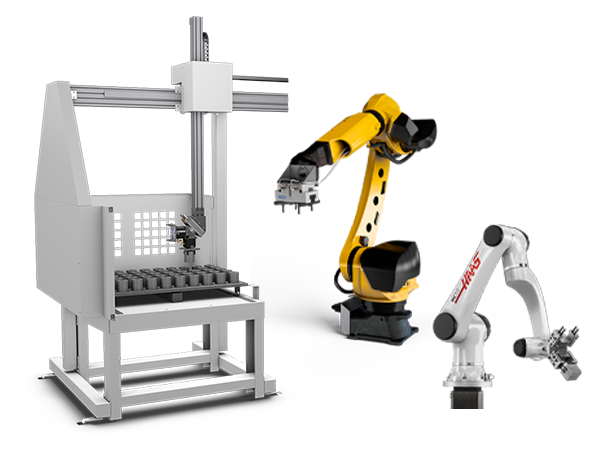
    • Product Image オートメーション システム
      オートメーション システム
      オートメーション システム すべて表示
      • オートメーション システム
      • ミルの自動化
      • 旋盤の自動化
      • 自動化モデル
    • Haasドリルセンター デスクトップ機械
      デスクトップ機械
      デスクトップ機械 すべて表示
      • デスクトップ機械
      • デスクトップミル
      • デスクトップ旋盤
    • Haas工場機器 工場機器
      工場機器
      工場機器 すべて表示
      • 工場機器
      • バンドソー
      • ニーミル
      • 表面グラインダー、2550
      • 表面グラインダー、3063
      • レーザー切断機械
    • クイックリンク 特殊シリーズ  特殊シリーズ 
      EUシリーズ EUシリーズ 構築と価格 | 価格表 構築と価格 | 価格表 在庫のある機械 在庫のある機械 最新情報 最新情報 初めてのCNC 初めてのCNC
      ショッピングツール
      • Haas オンライン見積もり
      • 価格表
      • 在庫状況
      • CNCAローン
      問い合わせる

      HAAS ファクトリーアウトレット(HFO)がご質問にお応えし、最適なオプションをご案内します。

      CONTACT YOUR DISTRIBUTOR >
  • オプション Main Menu
    • Product Image スピンドル
      スピンドル
      スピンドル すべて表示
      • スピンドル
    • Product Image ツールチェンジャー
      ツールチェンジャー
      ツールチェンジャー すべて表示
      • ツールチェンジャー
    • Product Image 第4軸 | 第5軸
      第4軸 | 第5軸
      第4軸 | 第5軸 すべて表示
      • 第4軸 | 第5軸
    • Product Image タレットと回転工具
      タレットと回転工具
      タレットと回転工具 すべて表示
      • タレットと回転工具
    • Product Image 検査
      検査
      検査 すべて表示
      • 検査
    • Haas切粉およびクーラントの管理 チップおよびクーラントの管理
      チップおよびクーラントの管理
      チップおよびクーラントの管理 すべて表示
      • チップおよびクーラントの管理
    • Haas制御 Haas制御
      Haas制御
      Haas制御 すべて表示
      • Haas制御
    • Product Image 生産オプション
      生産オプション
      生産オプション すべて表示
      • 生産オプション
    • Product Image ツーリングおよび固定具
      ツーリングおよび固定具
      ツーリングおよび固定具 すべて表示
      • ツーリングおよび固定具
    • Product Image 保持具
      保持具
      保持具 すべて表示
      • 保持具
    • Product Image 5軸ソリューション
      5軸ソリューション
      5軸ソリューション すべて表示
      • 5軸ソリューション
      • 5 Easy Steps to 5-Axis
    • Product Image 自動化
      自動化
      自動化 すべて表示
      • 自動化
    • クイックリンク 特殊シリーズ  特殊シリーズ 
      EUシリーズ EUシリーズ 構築と価格 | 価格表 構築と価格 | 価格表 在庫のある機械 在庫のある機械 最新情報 最新情報 初めてのCNC 初めてのCNC
      ショッピングツール
      • Haas オンライン見積もり
      • 価格表
      • 在庫状況
      • CNCAローン
      問い合わせる

      HAAS ファクトリーアウトレット(HFO)がご質問にお応えし、最適なオプションをご案内します。

      CONTACT YOUR DISTRIBUTOR >
  • Why Haas Main Menu
      Haasの特徴を見る
    • Haasである理由
    • MyHaas
    • トレーニングコミュニティ
    • インダストリー4.0
    • Haas認定
    • お客様の声
  • サービス Main Menu
      Haas Service へようこそ
      サービス ホーム オペレーターマニュアル 手順 トラブルシューティング ガイド 予防メンテナンス Haasの部品 Haas Tooling ビデオ
  • ビデオ Main Menu
×

検索結果

Web Pages

画像

    • <
    • 1
    • >
MyHaas ようこそ、
!
Haas Tooling ゲストの注文履歴 MyHaas/HaasConnect サインイン 登録 Haas Tooling アカウント Order History Return History MyHaas/HaasConnect サインアウト ようこそ、 使用中の機械 最新の活動 見積 アカウント ユーザー サインアウト
販売代理店を検索
  1. 言語を選択
    1. English
    2. Deutsch
    3. Español - España
    4. Español - México
    5. Français
    6. Italiano
    7. Português
    8. Český
    9. Dansk
    10. Nederlands
    11. Magyar
    12. Polski
    13. Svenska
    14. Türkçe
    15. 中文
    16. Suomi
    17. Norsk
    18. الإنجليزية
    19. български
    20. Hrvatski
    21. Ελληνικά
    22. Română
    23. Slovenský
    24. Slovenščina
    25. 한국어
    26. 日本語
    27. Українська
×

検索結果

Web Pages

画像

    • <
    • 1
    • >

UMC C-Axis Rotary Encoder Ring - Replacement - AD0497

サービス ホーム 手順 アラーム検索: 4.103 UMC C軸ロータリーエンコーダーリング - 交換 - AD0497

UMC C軸ロータリーエンコーダーリング - 交換 - AD0497

- セクションに移動 - Back to Top

10.2 UMC ROTARY ENCODER RING - REPLACEMENT

Recently Updated Last updated: 06/13/2025

UMC C-Axis Rotary Encoder Ring - Replacement


AD0497

Revision A 06/2025

Introduction

This procedure details the replacement of the 3" C-Axis Encoder on all UMC machines and the 3" B-Axis Encoder on UMC -500/SS machines only.

Laser calibration is required to update the compensation table for the corresponding rotary axis following the encoder replacement. 

This document applies to the following Service Kits:

  • 93-3923  ENCDR NON-CONT KIT 3"ID SER HI-RES

Used on B & C-Axis:

  • UMC-500/SS

Used on C-Axis:

  • UMC-750/SS
  • UMC-1000/SS
  • UMC-1250/SS
  • UMC-1500-DUO/SS

Tools Required:

  • 99-2130 ANTI-OXIDANT COMPOUND ELECTRICAL
  • 99-2147 DIELECTRIC GREASE PACK SUPER LUBE
  • 0.008" Mylar Shim

C-Axis Encoder Ring Replacement

1

: Warning: Only certified service personnel should perform this procedure. Reorientation of Z-pulse or Trip-Flag will require laser calibration to populate rotary compensation tables with new, correct, values.

Zero-return all Axis.

Press [EMERGENCY STOP].

2

Handle jog B to +120°.

Remove the C-Axis bottom cover.

3

Press [SETTING].

Navigate to the Rotaty tab.

Un-Check the 4th Axis.

4

Press [DIAGNOSTIC].

Navigate to Parameters > Factory.

Set 7.083 C-Axis Linear Scale Enabled to "Scale Disabled".

Power off the machine.

5

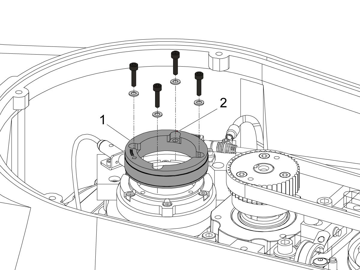
Uninstall the encoder read-head [1] by disconnecting the encoder cable [2] and removing the bolts and washers.

6

Note the Z-Pulse orientation before removing the encoder ring hub.

Uninstall the encoder ring hub [1] by removing the screws and washers mounting the encoder ring hub to the taper-lock. 

7

Mount and loosely install the encoder ring hub [1] from the service kit with the provided hardware, SHCS 10-32 X 3/4 (x4) and WASHER #10 FLAT (x4).

Verify the Z-Pulse is in the same location as the ring that was uninstalled. 

 Note: Do not torque mounting screws yet.

8

Turn on the machine.

Zero return all axis.

 Warning: Do not place the Mag Base anywhere near the Encoder.

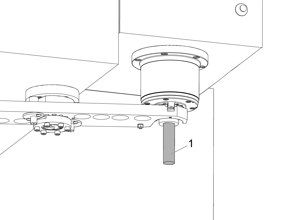
Check and document the runout on the OD of the scale encoder ring hub using the upper-most diameter, as shown.

Adjust as necessary. TIR must be 0.0005" or less.

Torque the 4 bolts of the encoder ring hub to 30 in-lbf in the star pattern.

After torquing, double check the runout to verify the ring hub has not shifted.

9

Clean the back surface of the encoder read-head and the mounting surface.

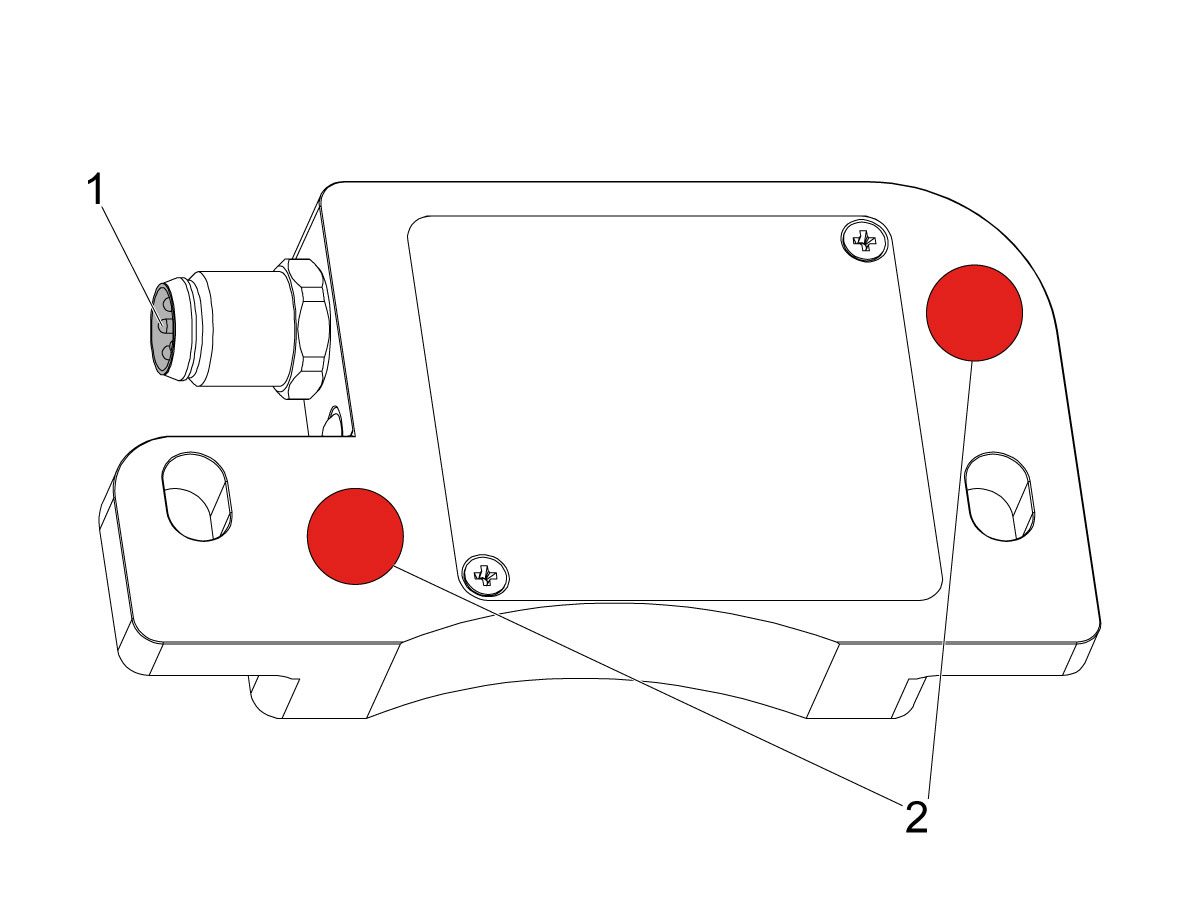
Add a small amount of silicone dielectric grease to encoder cable connection [1]. Grease should be a thin layer, but cover all the pins.

Apply two small drops of anti-oxidant (99-2130) to the mounting surface on the read head in the locations shown [2].

10

Connect the encoder cable [4] to the encoder read-head.

Insert cable by carefully lining up electrical pins with cable connector.

Install the encoder read-head [1] from the service kit with the provided hardware,  SHCS 8-32 x 1/2 bolts (x2) [2] and Washer .17ID x .4OD (2x) [3].

 Note: Do not torque mounting screws yet.

11

Set the gap between the scale ring and read-head as shown [1] using the appropriate mylar shim (0.008").

 Note: Do not use a metal shim.

Starting on the left side of the read-head [2], torque the two read-head mounting bolts to 20 in-lbf.

After torquing, double check the gap with the shim to verify the read-head has not shifted.

12

Reinstall the C-Axis bottom cover being sure no tools, shims, etc. have been left in the casting.

13

Press [SETTING].

Navigate to the Rotaty tab.

Check the 4th Axis.

Rotate the B-Axis back to zero when done.

14

Press [DIAGNOSTIC].

Navigate to Parameters > Configuration > Axis > B > Travel Limits.

Change: 6.108 B-Axis Positive Travel Limit from 180 to 110.

15

Press [DIAGNOSTIC].

Navigate to Parameters > Factory.

Set 7.083 C-Axis Linear Scale Enabled to "Scale Linear".

Power cycle the machine.

16

Zero-Return the C-Axis.

Zero-Return All Axis.

Set new Tool Change offset by following the UMC - X and Y Axes - Tool Change Offsets and the Side-Mount Tool Changer - Z-Axis Tool Change Offset - NGC procedures.

17

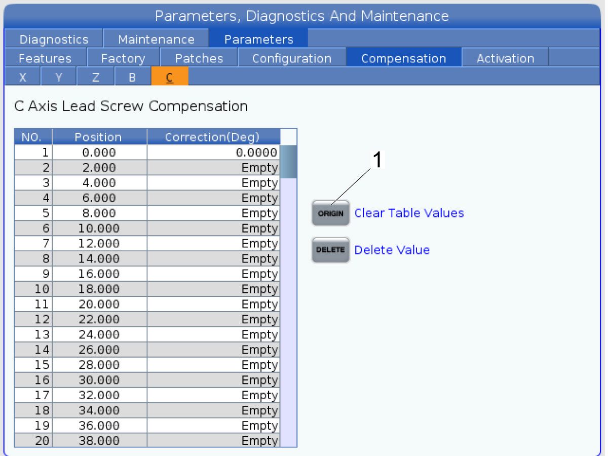
Clear the Compensation table for the C-Axis.

Press [DIAGNOSTIC].

Navigate to Parameters > Compensation > C.

Press [ORIGIN].

To update compensation table values for the C-Axis a laser calibration is required. The calculated compensation values will then be entered into the C-Axis Compensation Table.

B-Axis Encoder Ring Replacement

 Note: These step apply only to the UMC-500/SS B-Axis.

1

: Warning: Only certified service personnel should perform this procedure. Reorientation of Z-pulse or Trip-Flag will require laser calibration to populate rotary compensation tables with new, correct, values.

Zero-return all Axis.

Press [EMERGENCY STOP].

2

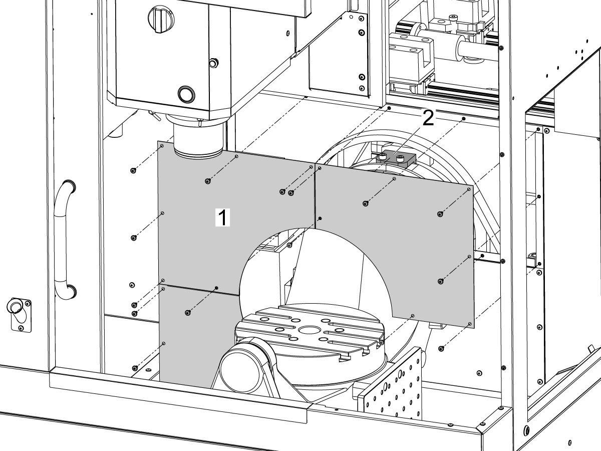
Remove the bulkhead sheet metal [1] to access the B-Axis hard stop [2]. 

3

Rotate the B-Axis approximately 100 degrees, or until there is enough room to access the hard stop [1].

Remove the B-Axis hard stop [1].

4

Remove the two rear sheet metal panels [1] to access the B-Axis components.

5

Insert a service key and enter service mode.

Press [DIAGNOSTIC].

Navigate to Parameters > Configuration > Axis > B > Travel Limits.

Change: 6.108 B-Axis Positive Travel Limit from 110 to 365.

6

Handle jog B to +180°.

Remove the C-Axis bottom cover.

7

Press [DIAGNOSTIC].

Navigate to Parameters > Factory.

Set 6.083 B-Axis Linear Scale Enabled to "Scale Disabled".

Power off the machine.

8

Disconnect all of the cables and hoses [1] running to the C-Axis through the B-Axis encoder ring. 

 Note: Mark the cables and hose to make reconnecting them easier later in this procedure. 

Remove the corrugated conduit [2].

9

Uninstall the encoder read-head [1] by disconnecting the encoder cable [2] and removing the bolts and washers.

10

Note the Z-Pulse orientation before removing the encoder ring hub.

Uninstall the encoder ring hub [1] by removing the screws and washers mounting the encoder ring hub to the taper-lock. 

11

Mount and loosely install the encoder ring hub [1] from the service kit with the provided hardware, SHCS 10-32 X 3/4 (x4) and WASHER #10 FLAT (x4).

Verify the Z-Pulse is in the same location as the ring that was uninstalled. 

 Note: If the Z-Pulse is in the wrong location the B-Axis will not zero return correctly and can damage the cables and hoses.

 Note: Do not torque mounting screws yet.

12

Route all of the cables and hoses [1] for the C-Axis through the corrugated conduit [2] and through the B-Axis encoder ring. 

Reconnect all of the cables and hoses to their original locations in the C-Axis.

13

Turn on the machine.

Zero return all axis.

 Note: The B-Axis should zero return in the Clockwise direction.

 Warning: Do not place the Mag Base anywhere near the Encoder.

Check and document the runout on the OD of the scale encoder ring hub using the upper-most diameter, as shown.

Adjust as necessary. TIR must be 0.0005" or less.

Torque the 4 bolts of the encoder ring hub to 30 in-lbf in the star pattern.

After torquing, double check the runout to verify the ring hub has not shifted.

14

Clean the back surface of the encoder read-head and the mounting surface.

Add a small amount of silicone dielectric grease to encoder cable connection [1]. Grease should be a thin layer, but cover all the pins.

Apply two small drops of anti-oxidant (99-2130) to the mounting surface on the read head in the locations shown [2].

15

Connect the encoder cable [1] to the encoder read-head.

Insert cable by carefully lining up electrical pins with cable connector.

Install the encoder read-head [2] from the service kit with the provided hardware,  SHCS 8-32 x 1/2 bolts (x2) [4] and Washer .17ID x .4OD (2x) [3].

 Note: Do not torque mounting screws yet.

16

Set the gap between the scale ring and read-head as shown [1] using the appropriate mylar shim (0.008").

 Note: Do not use a metal shim.

Starting on the left side of the read-head [2], torque the two read-head mounting bolts to 20 in-lbf.

After torquing, double check the gap with the shim to verify the read-head has not shifted.

17

Reinstall the C-Axis bottom cover being sure no tools, shims, etc. have been left in the casting.

 Note: You will have to set a new tool change offset and update compensation table values for the B-Axis. This will require laser calibration.

18

Rotate the B-Axis to the same position when the hard stop was removed. 

Install the B-Axis hard stop [1].

19

Press [DIAGNOSTIC].

Navigate to Parameters > Configuration > Axis > B > Travel Limits.

Change: 6.108 B-Axis Positive Travel Limit from 365 to 110.

Rotate the B-Axis back to zero when done.

20

Press [DIAGNOSTIC].

Navigate to Parameters > Factory.

Set 6.083 B-Axis Linear Scale Enabled to "Scale Linear".

Power cycle the machine.

21

Zero-Return the B-Axis.

Zero-Return All Axis.

Set new Tool Change offset by following the UMC - X and Y Axes - Tool Change Offsets and the Side-Mount Tool Changer - Z-Axis Tool Change Offset - NGC procedures.

22

Install the bulkhead sheet metal [1] once the B-Axis hard stop [2] has been installed. 

23

Install the two rear sheet metal panels [1].

24

Clear the Compensation table for the B-Axis.

Press [DIAGNOSTIC].

Navigate to Parameters > Compensation > B.

Press [ORIGIN].

To update compensation table values for the B-Axis a laser calibration is required. The calculated compensation values will then be entered into the B-Axis Compensation Table.

Recently Viewed Items

You Have No Recently Viewed Items Yet

フィードバック
Haas Logo

美元价格不包括关税、报关费用、保险费、增值税及运费。
USD prices DO NOT include customs duty, customs fees, insurance, VAT, or freight.

人民币价格包含关税、报关费用、货运保险和增值税, 但不包括运费。
CNY prices include customs duty, customs fees, insurance, and VAT. DOES NOT include freight.

Haas納入価格

この価格には、送料、輸出入関税、保険、およびお客様が購入者として同意されたフランスの宛先への配送中に発生するその他の費用が含まれます。Haas CNC製品の配送に他の必須費用を追加することはできません。

HAASに関する最新の情報と技術についてご紹介しています。

今すぐサインアップして下さい!   

HAAS TOOLING ACCEPTS THE FOLLOWING:

  • サービスおよびサポート
  • オーナー
  • サービスのリクエスト
  • オペレーターマニュアル
  • Haasの部品
  • ロータリーテーブルの修理リクエスト
  • 設置準備ガイド
  • ショッピングツール
  • 新しいHaasオンライン見積もり
  • 在庫状況
  • Haas製品の価格表
  • CNCAローン
  • Haasについて
  • DNSHステートメント
  • 採用情報
  • 認証と安全性
  • お問い合わせ
  • 会社沿革
  • ご利用規約
  • Haas Tooling ご利用規約
  • プライバシー
  • 保証
  • Haasコミュニティ
  • Haas 認定プログラム
  • Haas モータースポーツ
  • Gene Haas基金
  • HAAS技術トレーニングコミュニティ
  • イベント
  • 会話に参加する
  • Facebook
  • X
  • Flickr
  • YouTube
  • LinkedIn
  • Instagram
  • TikTok
© 2025 Haas Automation, Inc – CNC工作機械

This site is protected by reCAPTCHA and the Google Privacy Policy および Terms of Service apply.

2800 Sturgis Rd., Oxnard, CA 93030 / Toll Free: 800-331-6746
Phone: 805-278-1800 / Fax: 805-278-2255