My Haas Welcome,
!
Haas Tooling MyHaas/HaasConnect Sign In Register Haas Tooling MyHaas/HaasConnect Sign Out Welcome, My Machines Latest Activity My Quotes My Account My Users Sign Out
Find Your Distributor
  1. Select Language
    1. English
    2. Deutsch
    3. Español - ES
    4. Español - MX
    5. Français
    6. Italiano
    7. Português
    8. Český
    9. Dansk
    10. Nederlands
    11. Magyar
    12. Polski
    13. Svenska
    14. Türkçe
    15. 中文
    16. Suomi
    17. Norsk
    18. الإنجليزية
    19. български
    20. Hrvatski
    21. Ελληνικά
    22. Română
    23. Slovenský
    24. Slovenščina
    25. 한국어
    26. 日本語
    27. Українська
  • machines Main Menu
    • Vertical Mills
      Vertical Mills
      Vertical Mills View All
      • Vertical Mills
      • VF Series
      • Universal Machines
      • VR Series
      • VP-5 Prismatic
      • Pallet-Changing VMCs
      • Mini Mills
      • Mold Machines
      • High-Speed Drill Centers
      • Drill/Tap/ Mill Series
      • Toolroom Mills
      • Pocket Mill
      • Compact Mills
      • Gantry Series
      • SR Sheet Routers
      • Extra-Large VMC
      • Double-Column Mills
      • 3+2 Positioning Machines
    • Multi-Axis Solutions
      Multi-Axis Solutions
      Multi-Axis Solutions View All
      • Multi-Axis Solutions
      • Y-Axis Lathes
      • 5-Axis Mills
    • Lathes
      Lathes
      Lathes View All
      • Lathes
      • ST Series
      • Dual-Spindle
      • Box Way Series
      • Toolroom Lathes
      • Chucker Lathe
      • Pocket Lathe
      • Haas Bar Feeders
    • Horizontal Mills
      Horizontal Mills
      Horizontal Mills View All
      • Horizontal Mills
      • 50-Taper
      • 40-Taper
    • Rotaries & Indexers
      Rotaries & Indexers
      Rotaries & Indexers View All
      • Rotaries & Indexers
      • Rotary Tables
      • Indexers
      • 5-Axis Rotaries
      • Extra-Large Rotaries
    • Special Series
      Special Series
      Special Series View All
      • Special Series
      • EU_Series_Redirect
    • Automation Systems
      Automation Systems
      Automation Systems View All
      • Automation Systems
      • Mill Automation
      • Lathe Automation
      • Automatic Parts Loaders
      • Automation Models
    • Desktop Machines
      Desktop Machines
      Desktop Machines View All
      • Desktop Machines
      • Desktop Mill
      • Desktop Lathe
      • Control Simulator, Standard
      • Control Simulator, Premium
    • Shop Equipment
      Shop Equipment
      Shop Equipment View All
      • Shop Equipment
      • Knee Mill
      • Haas Manual Lathes
      • Haas Saws
    • Fabrication Machines
      Fabrication Machines
      Fabrication Machines View All
      • Fabrication Machines
      • Laser Cutting Machines
      • CNC Press Brakes
    • QUICK LINKS Special Series  Special Series 
      EU SERIES EU SERIES BUILD & PRICE | PRICE LIST BUILD & PRICE | PRICE LIST In-Stock Machines In-Stock Machines WHAT’S NEW WHAT’S NEW YOUR FIRST CNC YOUR FIRST CNC
      SHOPPING TOOLS
      • Build & Price a Haas
      • Price List
      • Available Inventory
      • CNCA Financing
      WANT TO TALK TO SOMEONE?

      A Haas Factory Outlet (HFO) can answer your questions, and walk you through your best options.

      CONTACT YOUR DISTRIBUTOR >
  • Options Main Menu
    • The Haas Control Value Option Packages
      Value Option Packages
      Value Option Packages View All
      • Value Option Packages
    • Product Image Spindles
      Spindles
      Spindles View All
      • Spindles
    • Product Image Tool Changers
      Tool Changers
      Tool Changers View All
      • Tool Changers
    • Product Image 4th- | 5th-Axis
      4th- | 5th-Axis
      4th- | 5th-Axis View All
      • 4th- | 5th-Axis
    • Product Image Turrets & Live Tooling
      Turrets & Live Tooling
      Turrets & Live Tooling View All
      • Turrets & Live Tooling
    • Product Image Probing
      Probing
      Probing View All
      • Probing
    • Haas Chip & Coolant Management Chip & Coolant Management
      Chip & Coolant Management
      Chip & Coolant Management View All
      • Chip & Coolant Management
    • The Haas Control The Haas Control
      The Haas Control
      The Haas Control View All
      • The Haas Control
    • Product Image Product Options
      Product Options
      Product Options View All
      • Product Options
    • Product Image Tooling & Fixturing
      Tooling & Fixturing
      Tooling & Fixturing View All
      • Tooling & Fixturing
    • Product Image Workholding
      Workholding
      Workholding View All
      • Workholding
    • Product Image 5-Axis Solutions
      5-Axis Solutions
      5-Axis Solutions View All
      • 5-Axis Solutions
      • 5 Easy Steps to 5-Axis
    • QUICK LINKS Special Series  Special Series 
      EU SERIES EU SERIES BUILD & PRICE | PRICE LIST BUILD & PRICE | PRICE LIST In-Stock Machines In-Stock Machines WHAT’S NEW WHAT’S NEW YOUR FIRST CNC YOUR FIRST CNC
      SHOPPING TOOLS
      • Build & Price a Haas
      • Price List
      • Available Inventory
      • CNCA Financing
      WANT TO TALK TO SOMEONE?

      A Haas Factory Outlet (HFO) can answer your questions, and walk you through your best options.

      CONTACT YOUR DISTRIBUTOR >
  • Why Haas Main Menu
      Discover the Haas Difference
    • Why Haas
    • MyHaas
    • Education Community
    • Industry 4.0
    • Haas Certification
    • Customer Testimonials
  • Service Main Menu
      Welcome to Haas Service
      SERVICE HOME Operator’s Manuals How-To Procedures Troubleshooting Guides Preventive Maintenance Haas Parts Haas Tooling Videos
  • Videos Main Menu
  • Main Menu
    • View All
    • View All
    • View All
    • View All
      • HTEC Curriculum Support
      • Haas Value Option Packages (VOP) Journey
    • View All
      • Haas 10 kg Cobot Package
      • Cobot Kits
      • DC-1 Drill Center
      • CNC Sales News
      • Do More With Your Haas
    • View All
    • View All
      • contact-us-test
      • 4 - AUTOMATION SYSTEMS
      • Carousel-V2
      • expert test
      • Demo_Day_Trident-test
      • Link Test
      • image-sale-tag-test
      • article-list-test
      • Haas 25 kg Robot Package
      • test-algolia-page
    • View All
    • View All
    • View All
    • View All
      • calc-test
    • View All
    • QUICK LINKS Special Series  Special Series 
      EU SERIES EU SERIES BUILD & PRICE | PRICE LIST BUILD & PRICE | PRICE LIST In-Stock Machines In-Stock Machines WHAT’S NEW WHAT’S NEW YOUR FIRST CNC YOUR FIRST CNC
      SHOPPING TOOLS
      • Build & Price a Haas
      • Price List
      • Available Inventory
      • CNCA Financing
      WANT TO TALK TO SOMEONE?

      A Haas Factory Outlet (HFO) can answer your questions, and walk you through your best options.

      CONTACT YOUR DISTRIBUTOR >
  • Haas Tooling Main Menu
  • Haas Service Parts Main Menu

My Haas Welcome,
!
Haas Tooling MyHaas/HaasConnect Sign In Register Haas Tooling MyHaas/HaasConnect Sign Out Welcome, My Machines Latest Activity My Quotes My Account My Users Sign Out
Find Your Distributor
  1. Select Language
    1. English
    2. Deutsch
    3. Español - ES
    4. Español - MX
    5. Français
    6. Italiano
    7. Português
    8. Český
    9. Dansk
    10. Nederlands
    11. Magyar
    12. Polski
    13. Svenska
    14. Türkçe
    15. 中文
    16. Suomi
    17. Norsk
    18. الإنجليزية
    19. български
    20. Hrvatski
    21. Ελληνικά
    22. Română
    23. Slovenský
    24. Slovenščina
    25. 한국어
    26. 日本語
    27. Українська
×

Search Results

Web Pages

Images

    • <
    • 1
    • >

Rotary Servo Control Box - Troubleshooting Guide - TG0122

Service Home Rotary Servo Control Box - Troubleshooting Guide - TG0122

Rotary Servo Control Box - Troubleshooting Guide - TG0122

- Jump to Cause - Back to Top

8.4 Rotary Servo Control Box - Troubleshooting

Recently Updated Last updated: 10/14/2025

Rotary Servo Control Box - Troubleshooting Guide


TG0122

Introduction

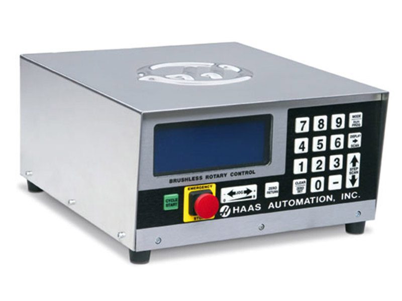
When used with any CNC machining center, the control performs as a semi-4th axis, activated by a single M-code.

You can program the control to rotate the rotary spindle in either direction, in step sizes from 0.001° to 999.999°.

There can be up to 99 different steps in memory, and each step can be repeated (or looped) up to 999 times.

Non-volatile memory retains programs, even when the power is turned off, and you can store up to 10 separate programs. 

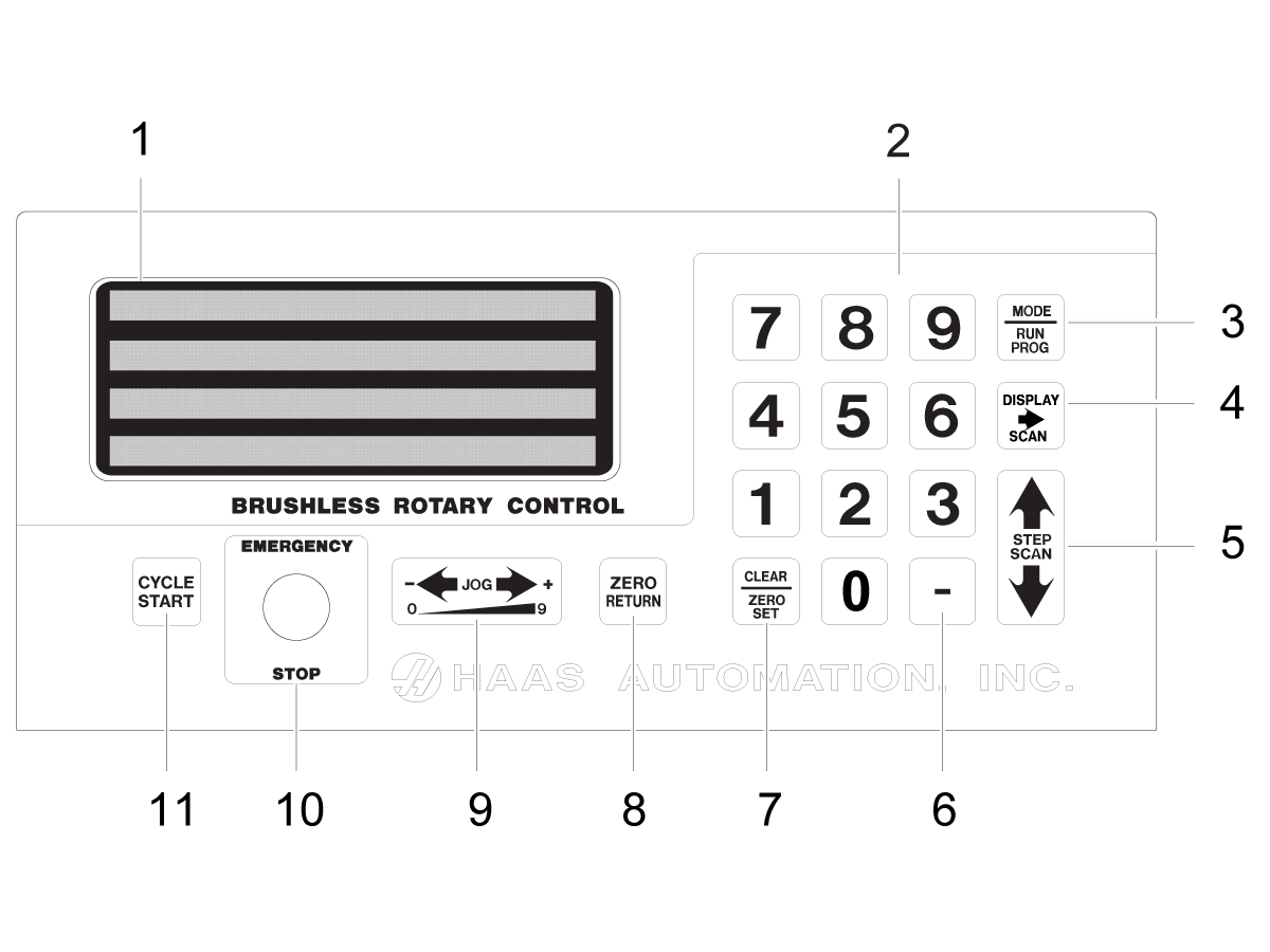
Servo Control - Front Panel

Note: For replacement keypads order service kit
93-4411.
 
  1. Display – 4-lines show current data.

  2. 0 - 9 - Data entry keys and jog speed selection.

  3. MODE/RUN PROG – Switches from Run mode to Program mode (with blinking display).

  4. DISPLAY SCAN – Scans display to show either the screen with Position, Step Angle, Feed Rate, Loop Counts, G Code, and status line, or position and status line in RUN mode. It scans left/right in Program mode.

  5. STEP SCAN – Scans step numbers from 1 through 99 in Run mode. It scans up/down in Program mode.

  6. - (Minus) - Selects negative step values or Prog/Upload/Download functions. Feed Rate Override (50, 75 or 100%).

  7. CLEAR/ZERO SET – Clears the entered data, resets program to 0, or defines the present servo position as Home.

8. ZERO RETURN – Causes the servo to return to the Home position, search for mechanical Home, delete a step, or move forward to the mechanical offset.

9. Load meter – Indicates (%) of spindle load. A high load indicates excessive load or workpiece support misalignment. Hi-Load or Hi Curr alarms occur if not corrected. Damage to the motor or table may result if excessive loads continue. Refer to the "Troubleshooting" section, starting on page , for more information.

JOG– Causes the servo to move in either the forward + or backward - direction at a rate defined by the last numeric key pressed.

10. EMERGENCY STOP – Turns off the servo when on and aborts the step in progress.

11. CYCLE START – Begins a step, stops a continued operation, inserts a step, or turns the servo on.

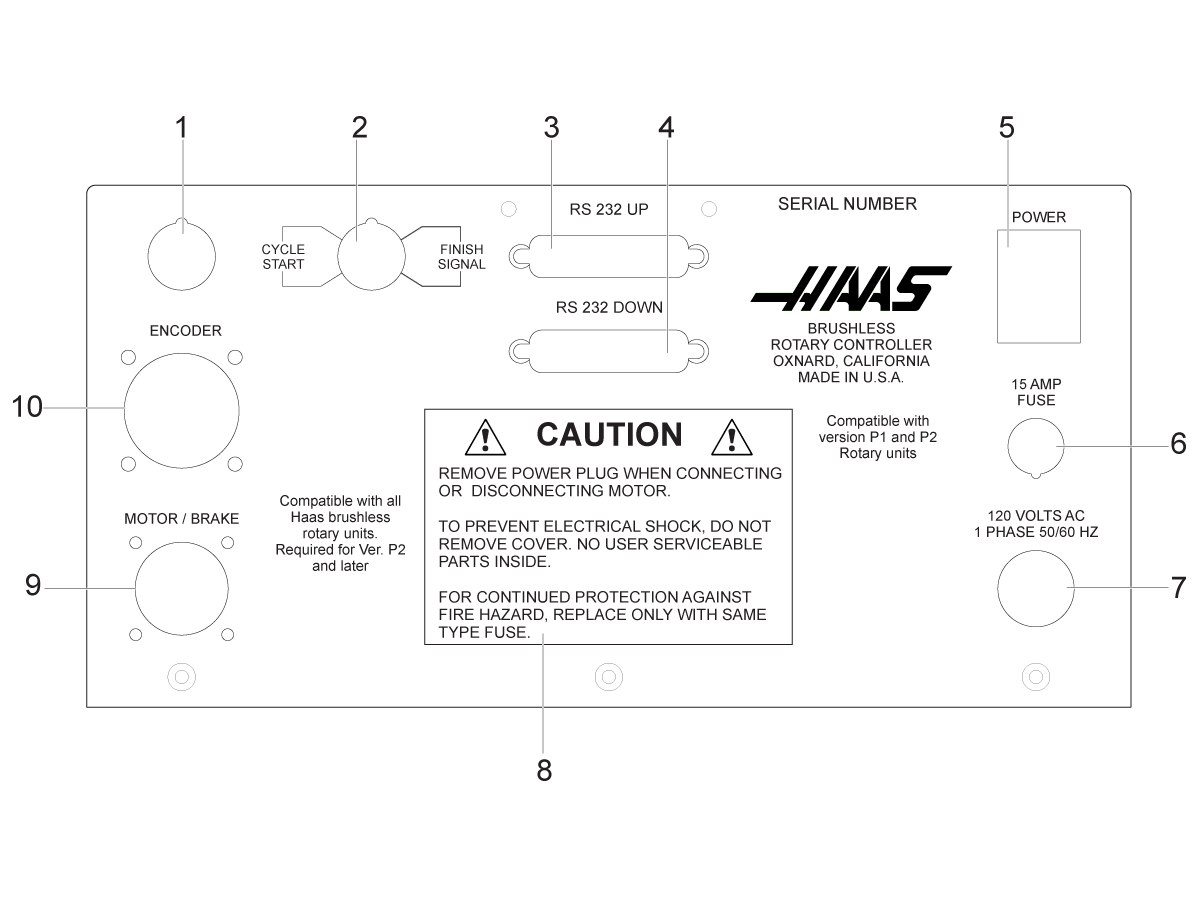
Servo Control - Rear Panel

  1. Unused access
  2. Remote input with Cycle Start and Finish Signal connections/Pin DIN connector for CNC interface cable.
  3. RS-232 Up Connector
  4. RS-232 Down Connector
  5. Power Switch
  6. 15 Amp Fuse
  7. 120VAC 1-phase 50/60 Hz power cord
  8. Caution label
  9. Motor / Brake Socket
  10. Encoder Socket

Servo Control - Display

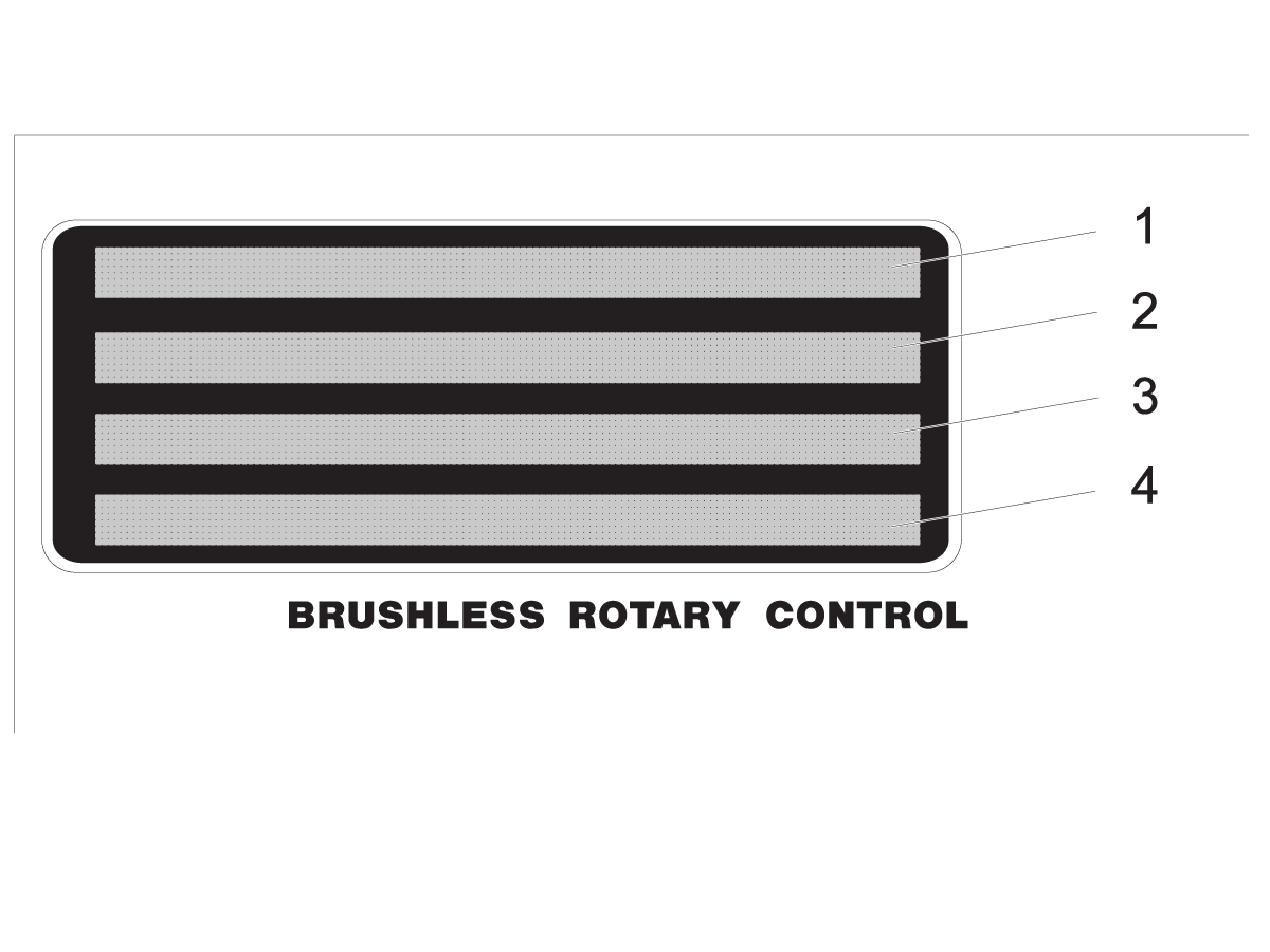
The display shows the program and mode for the rotary unit. The display consists of 4 lines with up to 80 characters per line. Data displayed includes:

  • Position (Spindle)
  • Step Size (Angle)
  • Feed Rate
  • Loop Count
  • G-Code
  • Current Step Number (Step numbers 1 to 99 are available)
  • Any Start-Up Errors or Alarms

The display highlights a single step of the program on display line 2. Press DISPLAY SCAN right arrow to scan sideways and see all the information for a single step, loops from left to right at the end of the row. Press STEP SCAN up arrow to display the previous step; press STEP SCAN down arrow to display the next step. You can scan to anywhere in the program with these keys. If a new number is entered in that position, the number is stored when scanned to another position or returned to Run mode.

Every step (or block) contains several pieces of information that are necessary for the program and are displayed simultaneously. The data is preceded by a letter(s) to indicate what type of information is displayed.

Each time you press the DISPLAY SCAN right arrow, the display cycles to the next register; that is, Position - Step Size - Feed Rate - Loop Count - G-Code - Position - etc. In Run mode, the DISPLAY SCAN right arrow button selects among any of these five displays. In Program mode, all of these but the Position may be displayed.

  1. The first line displays current spindle position (POS), followed by the G-Code display (G) then the loop count display (L).
  2. The second and third lines display the step number (N) followed by the step size, then the feed rate (F).The left three characters on the second or third line contain the step number from 1 to 99. They cannot be changed with the numeric keys and are selected by using the STEP SCAN arrow buttons.
  3. See item 2.
  4. The fourth line is the control status line. It provides three control operations: RUN, STOP, ALARM. These operations are followed by the percentage of load, and the last status of the air brake.

Power On - Error Codes

A set of self tests are run when the control is turned on and the results may indicate a control fault. These are displayed on the Alarm: 4th line.

NOTE:  Intermittent low voltage errors or power failures may be the result of inadequate power to the controller. Use short, heavy-duty extension cords. Make sure that the supplied power is a minimum of 15 amps at the plug.

ERROR Code  Probable Cuase  Corrective Action
Blank front panel Program CRC failure  Bad RAM, or cycle power if bad ROM to RAM program transfer. 
E0 EProm EPROM CRC error Internal EPROM chip on the main pcb has failed.  Contact your local Haas Factory Outlet.
Frt Pnel Short Front panel switch closed or shorted The control sense buttons or switches made during power on.  Check the buttons on the keypad and make sure they are not pushed in.
Remote Short Remote Start switch closed and enabled, or remote CNC input shorted. Remove the remote start cable and cycle power, if alarm goes away the cable or remote device has a short.
RAM Fault Memory fault Contact your local Haas Factory Outlet.
Stored Prg Flt Stored program fault (low battery) The internal battery is low.  Contact your local Haas Factory Outlet.
Power Failure Power failure interrupt (low line voltage) Check your incoming voltage.
Enc Chip Bad Encoder chip bad Contact your local Haas Factory Outlet.
Interrupt Flt Timer/interrupt fault Contact your local Haas Factory Outlet.
1khz Missing Clock generation logic failure (1 kHz signal missing) Contact your local Haas Factory Outlet.
Scal Cmp Lrge Exceeding maximum allowed rotary scales compensation. (HRT210SC only) Verify the parameters for the unit.
0 Margin Small (Zero margin too small) Distance between the home switch and the final motor position, after seeking home, is either less than 1/8 or greater than 7/8 of a motor revolution.  This alarm occurs while homing the rotary table. Parameter 45, for the A Axis, or Parameter 91, for the B Axis, must be set properly. Use the default value (0) for the axis parameter (45 or 91), and add 1/2 of a motor revolution. 1/2 motor revolution is calculated by taking the value in Parameter 28 for the A Axis, or Parameter 74 for the B Axis, and dividing by 2. Enter this value for parameter 45 or 91, and re-home the rotary table.
Enc Type Flt Detected motor type is different from the one specified by Parameter 60.  Contact your local Haas Factory Outlet.
Mot Detect Flt No motor detected at power-up or during control initialization. Check that the motor cables are connected to the control box.
C Init lt 4 Battery missing or dead Missing battery: Open the control box and place battery in battery holder.

Dead battery: Open the control box if an auxiliary battery board is present replace batteries.

If one is not present remove the battery soldered to the control board and install auxiliary battery board 93-32-4307, batteries not included with this part. 

Servo Off - Error Codes

Any time the servo (motor) is turned off, a reason code is displayed on the Alarm: 4th line, along with the following codes.

An A or B may precede the code for TRT units. This is the reference to the axis that caused the fault.

ERROR Code  Probable Cuase  Corrective Action
Por On Power just applied. This is a normal message at power on.
Servo Err Lrge The air brake did not disengaged. Remove the air from the rotary and see if the unit will now rotate without an alarm.  
The connection to the encoder or power is faulty. Check the encoder and power cable connections to the motor.
E-Stop Emergency stop on The Emergency stop button is active.  Pull the Emergency stop button and press Cycle Start.
Servo Overload The cutting tool is not sharp or is damaged. Install a new tool or a new tool insert.
There is a mechanical blockage in the axis of travel. Make sure the axis has a clear path of travel.
There is an internal mechanical obstruction in the rotary unit. Test the rotary unit.
The brake solenoid for the rotary unit has an electrical fault. Troubleshoot the brake solenoid.
RS-232 Problem Remote RS-232 commanded off Check the RS-232 cable to PC,  
Encoder Fault Z channel fault (bad encoder or cable) Test the axis motor cable for short.
Scale Z Fault Rotary scale Z channel fault (bad rotary scale encoder or cable) HRT210SC only Check the rotary scale cable.
Z Encod Missing Z channel missing (bad encoder or cable) Test the axis motor cable for short.
Scale Z Missing Rotary scale Z channel missing (bad rotary scale encoder or cable) (HRT210SC only) Check the rotary scale cable.
Regen Overheat High line voltage Check the incoming voltage to the servo control box.
Cable Fault Break detected in encoder cable wiring Test the axis motor cable for short.
Electrical noise has been detected when using Rotary controllers manufactured after April 2017 with one of the family cables 32-1990A, 32-1990B, or 32-1990C.

Order Service Kit 93-4980 Control Box Noise Reduction Kit. 

Remove the current encoder cable labled 36-4092A and replace with 36-4092B.

Remove the current Motor Brake Cable labeled 36-4193 and replace with 36-4193A.


Pwr Up Phase Er Power up phase error Test the axis motor cable for short.
Drive Fault An over current or drive fault. Test the axis motor cable for short.
Enc Trans Flt Encoder transition fault had been detected. Test the axis motor cable for short.
Indr Not Up Platter not fully up (HRT320FB only). Can be caused by low air pressure. Check the air connection to the HRT unit.

Remote Input Troubleshooting

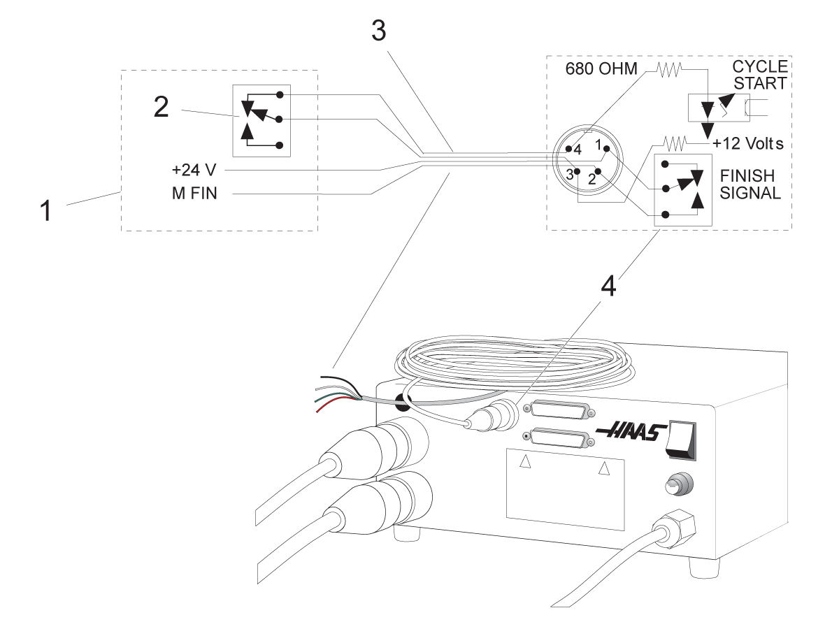
Servo Control Relay:

[1] CNC Mill Internal,

[2] M Function Relay,

[3] CNC Interface Cable,

[4] Servo Control Internal

Troubleshooting a Working Interface on a CNC

If there are problems, try to isolate the problem by checking the Servo Control and the mill separately. There are only two signals and each one can be checked separately from the other. If the rotary unit stops indexing because of an interface problem, follow these simple checks:

  • Check the Servo Control remote input alone
  • Check the CNC cable interface alone
  • Check the Servo Control and the mill together

Check Servo Control Remote Input Alone

To check the Servo Control remote input:

  1. Disconnect the remote cable from the back of the controller.
  2. Set the control to index a single step of 90°�.
  3. Connect a continuity tester or a voltmeter (a digital meter may not be fast enough to sample the brief pulse) set for low ohms across pins 1 and 2; they are marked on the rear of the control as FINISH SIGNAL.
  4. It must show an open circuit, otherwise check relay Parameter 1 (should be 1) and Parameter 2 (should be 0). The relay must show an open circuit with the control turned off, otherwise the relay is defective.
  5. Use a jumper wire to short pins 3 and 4 together, they are marked on the rear of the control as CYCLE START.
  6. The unit must index, and at the end of the index, the voltmeter should deflect briefly toward low ohms or continuity. If this works as described, the problem is NOT in the rotary control, but may be the interface cable or mill.

Check The CNC Cable Interface Alone

To check the CNC cable interface:

Check the signals from the CNC using your voltmeter.

NOTE: The pin orientation is reversed.

Execute an M function from the mill to rotate.

The mill beacon light should come on (green) and stay on.

Use the meter and check continuity across the CYCLE START pins 3 and 4. Try not to short the test leads and pins against the shield of the male plug.

note: Some mills may have a +12 to +24 volt signal on pin 4 to activate a rotary unit. Check if there is voltage between pin 4 and the ground, if the continuity test fails, this is also a valid CYCLE START signal. If there is voltage present on Pin 4, a Haas interface box must be used (Part # IB). Contact your dealer if there are questions on how to use the interface box.

To check the CYCLE FINISH signal, use a voltmeter test probe to short together pins 1 and 2 on the mill cable.

The mill beacon light should turn off.

Result: 

If the above tests pass, there is a valid signals coming from the mill.

Check Servo Control And Mill Together

To check the Servo Control and mill:

1. Reset the mill by pressing RESET or turn it off by pressing POWER OFF.

2. Connect the remote cable, then turn both the Servo Control and mill on.

Once connected, the rotary unit should remain idle. If the rotary unit moves, the CYCLE START signal from the mill is shorted.

3. If it remains idle, execute or MDI an M function from the mill to index.

Do not index from the program unless using single-block. If the rotary unit does not move, the mill is not outputting a signal or there is a break in the cable.

If the Servo Control indexes properly, ensure that the mill beacon light goes out at the end of the index. If the light does not go out, the CYCLE FINISH signal is not returning to the mill. This could be an open wire in the remote cable, or a problem in cables that connect to the CNC.

4.  If the unit works only in single block, but not in the Run mode, there may be a timing problem involving two M functions, or a simultaneous milling problem. Review the section on simultaneous milling. If there are two M functions, separate them with a dwell of ¼ second.

Recently Viewed Items

You Have No Recently Viewed Items Yet

Feedback
Haas Logo

Haas Delivered Price

This price includes shipping cost, export and import duties, insurance, and any other expenses incurred during shipping to a location in France agreed with you as a buyer. No other mandatory costs can be added to the delivery of a Haas CNC Product.

KEEP UP WITH THE LATEST HAAS TIPS AND TECHNOLOGY...

Sign up now!   

HAAS TOOLING ACCEPTS THE FOLLOWING:

  • Service & Support
  • Owners
  • Request Service
  • Operator Manuals
  • Haas Parts
  • Rotary Repair Request
  • Pre-Install Guides
  • Shopping Tools
  • Build & Price a New Haas
  • Available Inventory
  • The Haas Price List
  • CNCA Financing
  • About Haas
  • Accessibility Statement
  • DNSH Statement
  • Export Compliance
  • Careers
  • Certifications & Safety
  • Contact Us
  • History
  • Terms & Conditions
  • Haas Tooling Terms & Conditions
  • Privacy
  • Warranty
  • Haas Community
  • Haas Certification Program
  • Haas Motorsports
  • Gene Haas Foundation
  • Haas Technical Education Community
  • Events
  • Join the Conversation
  • Facebook
  • X
  • Flickr
  • YouTube
  • LinkedIn
  • Instagram
  • TikTok
© 2026 Haas Automation, Inc – CNC Machine Tools

This site is protected by reCAPTCHA and the Google Privacy Policy and Terms of Service apply.

2800 Sturgis Rd., Oxnard, CA 93030
Toll Free: (888) 817-4446 / Fax: 805-278-8554