My Haas Welcome,
!
Haas Tooling MyHaas/HaasConnect Sign In Register Haas Tooling MyHaas/HaasConnect Sign Out Welcome, My Machines Latest Activity My Quotes My Account My Users Sign Out
Find Your Distributor
  1. Select Language
    1. English
    2. Deutsch
    3. Español - ES
    4. Español - MX
    5. Français
    6. Italiano
    7. Português
    8. Český
    9. Dansk
    10. Nederlands
    11. Magyar
    12. Polski
    13. Svenska
    14. Türkçe
    15. 中文
    16. Suomi
    17. Norsk
    18. الإنجليزية
    19. български
    20. Hrvatski
    21. Ελληνικά
    22. Română
    23. Slovenský
    24. Slovenščina
    25. 한국어
    26. 日本語
    27. Українська
  • machines Main Menu
    • Vertical Mills
      Vertical Mills
      Vertical Mills View All
      • Vertical Mills
      • VF Series
      • Universal Machines
      • VR Series
      • VP-5 Prismatic
      • Pallet-Changing VMCs
      • Mini Mills
      • Mold Machines
      • High-Speed Drill Centers
      • Drill/Tap/ Mill Series
      • Toolroom Mills
      • Pocket Mill
      • Compact Mills
      • Gantry Series
      • SR Sheet Routers
      • Extra-Large VMC
      • Double-Column Mills
      • 3+2 Positioning Machines
    • Multi-Axis Solutions
      Multi-Axis Solutions
      Multi-Axis Solutions View All
      • Multi-Axis Solutions
      • Y-Axis Lathes
      • 5-Axis Mills
    • Lathes
      Lathes
      Lathes View All
      • Lathes
      • ST Series
      • Dual-Spindle
      • Box Way Series
      • Toolroom Lathes
      • Chucker Lathe
      • Pocket Lathe
      • Haas Bar Feeders
    • Horizontal Mills
      Horizontal Mills
      Horizontal Mills View All
      • Horizontal Mills
      • 50-Taper
      • 40-Taper
    • Rotaries & Indexers
      Rotaries & Indexers
      Rotaries & Indexers View All
      • Rotaries & Indexers
      • Rotary Tables
      • Indexers
      • 5-Axis Rotaries
      • Extra-Large Rotaries
    • Special Series
      Special Series
      Special Series View All
      • Special Series
      • EU_Series_Redirect
    • Automation Systems
      Automation Systems
      Automation Systems View All
      • Automation Systems
      • Mill Automation
      • Lathe Automation
      • Automatic Parts Loaders
      • Automation Models
    • Desktop Machines
      Desktop Machines
      Desktop Machines View All
      • Desktop Machines
      • Desktop Mill
      • Desktop Lathe
      • Control Simulator, Standard
      • Control Simulator, Premium
    • Shop Equipment
      Shop Equipment
      Shop Equipment View All
      • Shop Equipment
      • Knee Mill
      • Haas Manual Lathes
      • Haas Saws
    • Fabrication Machines
      Fabrication Machines
      Fabrication Machines View All
      • Fabrication Machines
      • Laser Cutting Machines
      • CNC Press Brakes
    • QUICK LINKS Special Series  Special Series 
      EU SERIES EU SERIES BUILD & PRICE | PRICE LIST BUILD & PRICE | PRICE LIST In-Stock Machines In-Stock Machines WHAT’S NEW WHAT’S NEW YOUR FIRST CNC YOUR FIRST CNC
      SHOPPING TOOLS
      • Build & Price a Haas
      • Price List
      • Available Inventory
      • CNCA Financing
      WANT TO TALK TO SOMEONE?

      A Haas Factory Outlet (HFO) can answer your questions, and walk you through your best options.

      CONTACT YOUR DISTRIBUTOR >
  • Options Main Menu
    • The Haas Control Value Option Packages
      Value Option Packages
      Value Option Packages View All
      • Value Option Packages
    • Product Image Spindles
      Spindles
      Spindles View All
      • Spindles
    • Product Image Tool Changers
      Tool Changers
      Tool Changers View All
      • Tool Changers
    • Product Image 4th- | 5th-Axis
      4th- | 5th-Axis
      4th- | 5th-Axis View All
      • 4th- | 5th-Axis
    • Product Image Turrets & Live Tooling
      Turrets & Live Tooling
      Turrets & Live Tooling View All
      • Turrets & Live Tooling
    • Product Image Probing
      Probing
      Probing View All
      • Probing
    • Haas Chip & Coolant Management Chip & Coolant Management
      Chip & Coolant Management
      Chip & Coolant Management View All
      • Chip & Coolant Management
    • The Haas Control The Haas Control
      The Haas Control
      The Haas Control View All
      • The Haas Control
    • Product Image Product Options
      Product Options
      Product Options View All
      • Product Options
    • Product Image Tooling & Fixturing
      Tooling & Fixturing
      Tooling & Fixturing View All
      • Tooling & Fixturing
    • Product Image Workholding
      Workholding
      Workholding View All
      • Workholding
    • Product Image 5-Axis Solutions
      5-Axis Solutions
      5-Axis Solutions View All
      • 5-Axis Solutions
      • 5 Easy Steps to 5-Axis
    • QUICK LINKS Special Series  Special Series 
      EU SERIES EU SERIES BUILD & PRICE | PRICE LIST BUILD & PRICE | PRICE LIST In-Stock Machines In-Stock Machines WHAT’S NEW WHAT’S NEW YOUR FIRST CNC YOUR FIRST CNC
      SHOPPING TOOLS
      • Build & Price a Haas
      • Price List
      • Available Inventory
      • CNCA Financing
      WANT TO TALK TO SOMEONE?

      A Haas Factory Outlet (HFO) can answer your questions, and walk you through your best options.

      CONTACT YOUR DISTRIBUTOR >
  • Why Haas Main Menu
      Discover the Haas Difference
    • Why Haas
    • MyHaas
    • Education Community
    • Industry 4.0
    • Haas Certification
    • Customer Testimonials
  • Service Main Menu
      Welcome to Haas Service
      SERVICE HOME Operator’s Manuals How-To Procedures Troubleshooting Guides Preventive Maintenance Haas Parts Haas Tooling Videos
  • Videos Main Menu
  • Main Menu
    • View All
    • View All
    • View All
    • View All
      • HTEC Curriculum Support
      • Haas Value Option Packages (VOP) Journey
    • View All
      • Haas 10 kg Cobot Package
      • Cobot Kits
      • DC-1 Drill Center
      • CNC Sales News
      • Do More With Your Haas
    • View All
    • View All
      • contact-us-test
      • 4 - AUTOMATION SYSTEMS
      • Carousel-V2
      • expert test
      • Demo_Day_Trident-test
      • Link Test
      • image-sale-tag-test
      • article-list-test
      • Haas 25 kg Robot Package
      • test-algolia-page
    • View All
    • View All
    • View All
    • View All
      • calc-test
    • View All
    • QUICK LINKS Special Series  Special Series 
      EU SERIES EU SERIES BUILD & PRICE | PRICE LIST BUILD & PRICE | PRICE LIST In-Stock Machines In-Stock Machines WHAT’S NEW WHAT’S NEW YOUR FIRST CNC YOUR FIRST CNC
      SHOPPING TOOLS
      • Build & Price a Haas
      • Price List
      • Available Inventory
      • CNCA Financing
      WANT TO TALK TO SOMEONE?

      A Haas Factory Outlet (HFO) can answer your questions, and walk you through your best options.

      CONTACT YOUR DISTRIBUTOR >
  • Haas Tooling Main Menu
  • Haas Service Parts Main Menu

My Haas Welcome,
!
Haas Tooling MyHaas/HaasConnect Sign In Register Haas Tooling MyHaas/HaasConnect Sign Out Welcome, My Machines Latest Activity My Quotes My Account My Users Sign Out
Find Your Distributor
  1. Select Language
    1. English
    2. Deutsch
    3. Español - ES
    4. Español - MX
    5. Français
    6. Italiano
    7. Português
    8. Český
    9. Dansk
    10. Nederlands
    11. Magyar
    12. Polski
    13. Svenska
    14. Türkçe
    15. 中文
    16. Suomi
    17. Norsk
    18. الإنجليزية
    19. български
    20. Hrvatski
    21. Ελληνικά
    22. Română
    23. Slovenský
    24. Slovenščina
    25. 한국어
    26. 日本語
    27. Українська
×

Search Results

Web Pages

Images

    • <
    • 1
    • >

VR/GM - H-5AX Spindle Chiller - Upgrade - AD0841

Service Home How To Procedures VR/GM - H-5AX Spindle Chiller - Upgrade - AD0841

VR/GM - H-5AX Spindle Chiller - Upgrade - AD0841

- Jump to Section - 1. Introduction 2. VR/GM Heat Exchanger Removal (9 steps) 3. VR/GM Spindle Chiller Installation (22 steps) 4. VR/GM Spindle Chiller Electrical Schematic 5. Spindle Motor Temperature Gauge 6. VR/GM Spindle Chiller Parameter Set up 7. Verification Back to Top
Recently Updated Last updated: 02/13/2026

VR/GM - H-5AX Spindle Chiller - Upgrade


AD0841

Revision B - 02/2026

Introduction

This procedure shows how to upgrade the H-5AX spindle chiller on VR and GM machines. 

This document applies to the following service kits:

  • 93-4864 SPINDLE CHILLER UPGRADE INSTALL KIT VR
  • 93-4889 SPINDLE CHILLER UPGRADE INSTALL KIT GM

Machine Requirements:

  • H-5AX Spindle Head
  • Software: 100.20.000.1200 or higher
  • Service Key

VR/GM Heat Exchanger Removal

1

 Note: A VR machine is used for illustrative purposes. The steps also will apply to the GM-5AX machines.

Home the Z-Axis. 

Press [EMERGENCY STOP].

Remove the sheet metal to gain access to the spindle head hose connections.

2

Disconnect the return hose [1] from the inlet port [2] on the VR/GM Spindle Heat Exchanger. 

Place the end of the disconnected return hose [1] into a separate container [3] to collect the chiller fluid.

3

With a service key in the control, enter service mode.

Press [DIAGNOSTIC].

Navigate to the I/O tab.

Turn on the spindle fan [1] in the I/O table to run the chiller.

Run the chiller until most of the VR/GM Heat Exchange fluid has been removed from the tank.

Turn off the fan to stop the chiller.

4

Disconnect the remaining hose [1] from the outlet port [2] on the VR/GM Spindle Heat Exchanger. 

Disconnect all cables [3] connected to the VR/GM Spindle Heat Exchanger.

5

Disconnect the spindle chiller hoses [1] from the fittings at the top of the machine.

Remove the spindle chiller hoses [1] from the cable carrier [2] and the coolant grommet brackets [3].

6

Remove the VR/GM Spindle Heat Exchanger [1] from the chiller bracket.

7

Remove the VR/GM Spindle Heat Exchanger bracket [1] from the column casting.

8

Remove the three thumb knobs [1], the cover [2], and the three STANDOFF 6-32M X 6-32M X 4 IN [3].

9

Note: Disconnecting the cables from the HSD board can help with the removal process but is not needed. If the cables are removed be sure to make note of their location on the board.

Remove the four nuts [1], the HSD board [2] and the four standoffs [3].

VR/GM Spindle Chiller Installation

1

Install the VR/GM Spindle Chiller bracket [1] from the kit on to the column.

2

Remove the screws holding the rubber feet [2] to the bottom of the chiller.

Note: The VR/GM Spindle Chiller, without chiller fluid, weighs approximately 80 lbs. (36.29 kg). Use an appropriate lifting mechanism to help install the chiller.

Install the VR/GM Spindle Chiller [1] onto the bracket using the M5 X .8 X 35 SHCS and #10 flat washers provided in the kit.

Note: The rubber feet [2] will be placed in between the chiller and the bracket.

3

For H-5AX Single Yokes only:

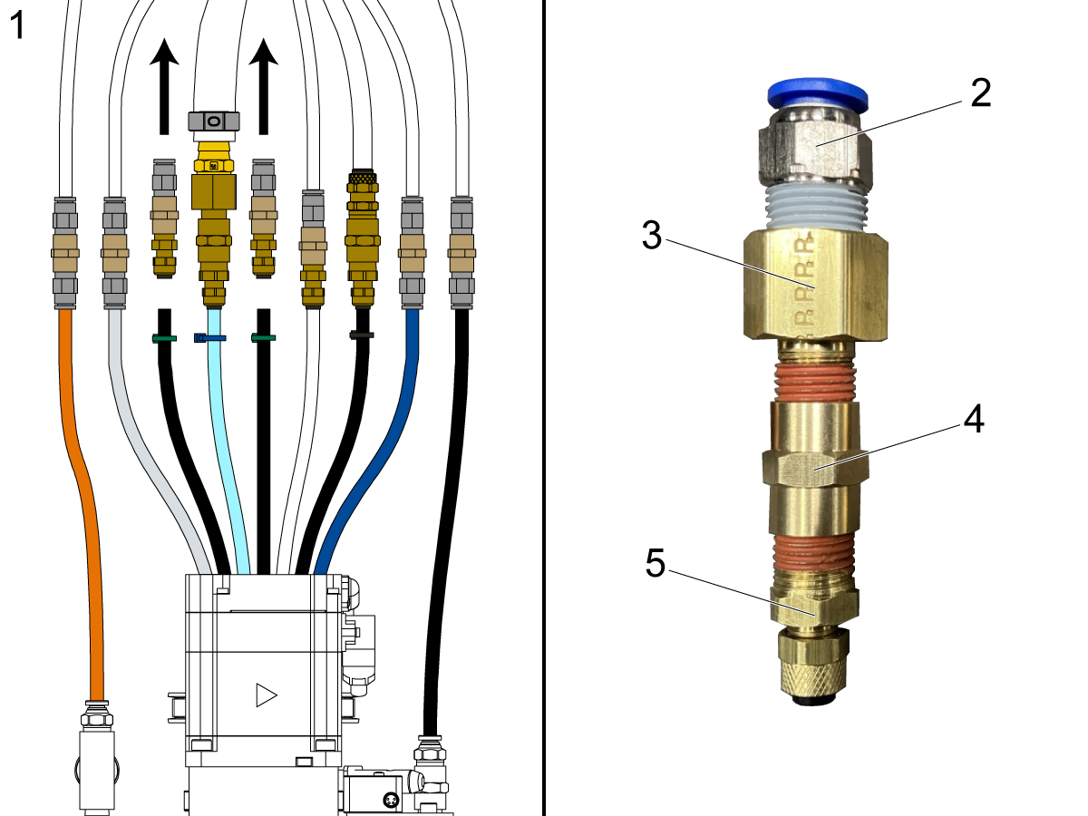
Remove the two chiller hose fittings [1] in the spindle head manifold.

Attach the following fittings into the configuration shown in the image:

  • [2] 58-2234 FITG PC10MMF NPT3/8M STR
  • [3] 58-1686 FITG REDUCER NPT3/8F NPT1/4M STR BRASS
  • [4] 58-2065 FITG NPT1/4F NPT1/4F STR BRASS
  • [5] 58-1674 FITG REDUCER NPT1/4M NPT1/8M STR BRASS

Note: There will be two left over fittings, 58-16708 FITG POLY1/4F NPT1/4M STR BRASS. These are for machines with Double Yoke heads. 

4

For H-5AX Double Yokes only:

Remove the two chiller hose fittings [1] in the spindle head.

Attach the following fittings into the configuration shown in the image:

  • [2] 58-2234 FITG PC10MMF NPT3/8M STR
  • [3] 58-1686 FITG REDUCER NPT3/8F NPT1/4M STR BRASS
  • [4] 58-2065 FITG NPT1/4F NPT1/4F STR BRASS
  • [5] 58-16708 FITG POLY1/4F NPT1/4M STR BRASS

Note: There will be two left over fittings, 58-1674 FITG REDUCER NPT1/4M NPT1/8M STR BRASS. These are for machines with Single Yoke heads. 

5

If available, use the four lower bolt holes [1] to mount the chiller contactor assembly instead of the original bolt holes [2] for the HSD board.

6

Install the chiller contactor assembly [1]. Use the four STANDOFF .187ID X 0.5LG  [2] to keep the contactor away from the back of the control cabinet.

Install the three STANDOFF 6-32M X 6-32M X 4 IN [3] on the contactor assembly. 

7

Connect cable 33-1381 [1] to the power distribution block [2] on the transformer.

Remove cable 33-2087 from P66 on the I/O board.

Connect the spindle fan [3] cable to P66 in the I/O board.

Route cable 33-1386 [4] out the bottom of the control cabinet. 

8

Install the HSD board [1] onto the chiller contactor.

Install the three STANDOFF 6-32 X 2 AL ML/FML 1/4 HEX [2] onto the HSD board [1].

9

Install the HSD cover [1] and thumb knobs.

10

For VR machines built before 10/2023:

Remove the sheet metal underneath the control cabinet [1] and on the back of the column to gain access to the cable channel [2].

11

For VR machines built before 10/2023:

Remove cable 33-2087 [1] from the cable channel running along the back of the column.

Route the chiller power cable (33-1479) [2] underneath the control cabinet and along the back of the column. Use magnets [3] and zip ties to secure the cable to the column above the cable channel.

Verify the cable will reach the chillers power outlet. Adjust the magnet placement if needed. 

12

For VR machines built before 10/2023:

Install the sheet metal that was removed from underneath the control cabinet [1] and on the back of the column [2].

Note: Be careful not to pinch any cables or hoses. 

13

For VR machines built 10/2023 and later:

Remove the sheet metal underneath the control cabinet [1] to gain access to the cables.

14

For VR machines built 10/2023 and later:

Remove cable 33-2087 [1] from the cable conduit running through the base of the column.

Route the chiller power cable (33-1479) [2] in the cable conduit, underneath the control cabinet and through the base of the column. 

15

For VR machines built 10/2023 and later:

Install the sheet metal that was removed from underneath the control cabinet [1].

Note: Be careful not to pinch any cables or hoses. 

16

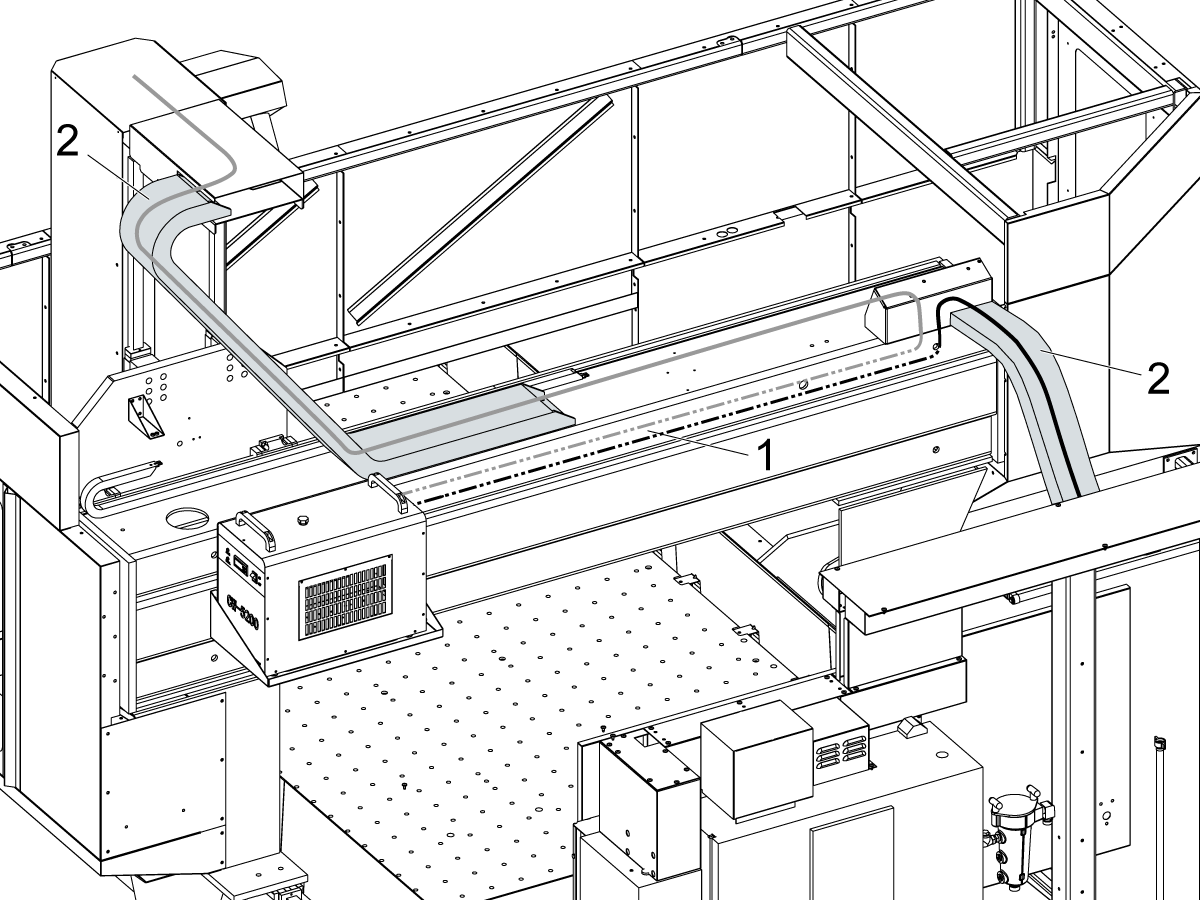
For GM machines :

The hoses and cables should be routed the same way the original ones were, through the bridge [1] and cable carriers [2].

17

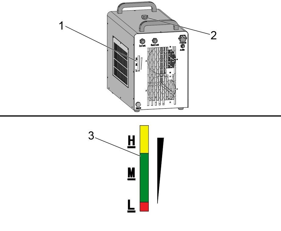
Inspect the fluid tank level by looking at the fluid level gauge located on the back of the spindle chiller [1]. To add fluid to the tank, remove the cap to the inlet [2] at the top of the unit, and fill the tank with Mobil Velocite Oil No 3 (PN: 93-4894) until the gauge reads the level is at the top of the M [3] or at the H level.

18

Place a funnel [1] in the intake cap.

Fill the chiller with the provided chiller fluid [2].

Note: The VR/GM Spindle Chiller uses Mobil Velocite Oil No 3 (PN: 93-4894).

Note: The chiller fluid capacity is 8 Liters.

19

Connect one of the hoses [1] to the outlet port.

Connect the chiller signal cable to the spindle flow SW on the chiller bracket sensor cable (33-2092).

Connect the power [2] and signal cable [3] to the chiller.

20

Flush the remaining VR/GM Heat Exchanger fluid from the system.

Place the end of the disconnected return hose [1] into a separate container [3] to collect the chiller fluid.

21

With a service key in the control, enter service mode.

Press [DIAGNOSTIC].

Navigate to the I/O tab.

Turn on the spindle fan [1] in the I/O table to run the chiller.

Run the chiller until the yellow/green VR/GM Heat Exchange fluid changes to the pale-yellow Mobil Velocite Oil No 3.

While the chiller is running, verify there is no leaking from the fittings in the spindle head. Leaking indicates loose fittings or loose hose connection.

Turn off the fan to stop the chiller.

22

Install any the sheet metal [1] that was removed to gain access to the spindle head hose connections.

VR/GM Spindle Chiller Electrical Schematic

There are 3 cables that go from the spindle chiller to the control cabinet:

  • Ground cable [1] - From spindle chiller to control cabinet chassis
  • Flow alarm cable 33-1360 - From alarm port to cable 33-2092  (VR) / 33-2094 (GM) which is connected to P39 on the I/O PCB.
  • Power cable 33-1479 (VR) / 33-1478 (GM) - From power socket to P31 on the I/O PCB.

Important: The alarm cable from the spindle chiller needs to be connected to the SPINDL FLOW connector of 33-2092  (VR) / 33-2094 (GM). This cable has 3 connectors, only the connector labeled SPINDL FLOW should be used.

Spindle Motor Temperature Gauge

The Spindle Motor Temperature Gauge [1] will continuously display either 0° F or –18° C, depending if Setting 9 is set to INCH or MM.

This is expected behavior for the VR/GM Spindle Chiller.

The alarm cable from the spindle chiller is connected to the SPINDL FLOW connector on 33‑2092 (VR) / 33‑2094 (GM). This cable has three connectors; only the connector labeled SPINDL FLOW is used. The CHILLER TEMP connector—which normally displays on the Spindle Motor Temperature Gauge [1]—is not used for the VR/GM Spindle Chiller.

The chiller temperature and temperature alarms are now displayed directly on the chiller screen. Refer to the Troubleshooting Symptom Table for more information on chiller alarms.

VR/GM Spindle Chiller Parameter Set up

The spindle chiller is automatically powered on when the spindle is operated, or when a tool change occurs. The power button on the front of the spindle chiller does not need to be changed. The spindle chiller uses a parameter based system to determine how much cooling needs to be done. These parameters need to be set when installing a new VR/GM Spindle Chiller.

 Note: Parameters are labeled F0-F9. Refer to the table in the Parameter Functions section of the VR/GM - Haas Spindle Chiller Operation for an explanation of the parameters.

1

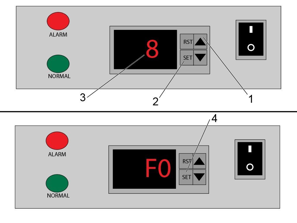
To view the parameter values on the spindle chiller, follow these steps:

  1. Press and hold the [UP] arrow [1] on the chiller control.
  2. Press and hold the [SET] button [2] while still holding the up arrow. There needs to be about a half second delay between pressing the [UP] arrow and the [SET] button in order to access the parameters.
  3. Hold these buttons until the display on the chiller shows a "0". Press the arrow keys until the display shows "8" [3] as shown in the top image and then press the [SET] button to navigate into the parameters page.
  4. Once in the parameters page, you can press the arrow keys to navigate to different parameters. Each parameter has a value that can be accessed by pressing the [SET] button.

2

After entering the parameters page and navigating to F0 using the arrow keys, press the [SET] button [1] to view the current parameter value. The value will appear on the display [2]. Verify the value is set to 25 degrees Celsius. 

If needed, adjust the value to 25 degrees Celsius by using the arrows. To set the new value press the [SET] button [3] again.

Pressing [SET] will return you to the parameter page.

3

After entering the parameters page and navigating to F1 using the arrow keys, press the [SET] button [1] to view the current parameter value. The value will appear on the display [2] and adjust the value to 0 degrees Celsius by using the arrows. To set the new value press the [SET] button [3] again.

After the parameter values are adjusted, press [RESET] (RTS) [4] to return to the main temperature screen.

4

After entering the parameters page and navigating to F2 using the arrow keys, press the [SET] button [1] to view the current parameter value. The value will appear on the display [2] and adjust the value to 3 degrees Celsius by using the arrows. To set the new value press the [SET] button [3] again.

After the parameter values are adjusted, press [RESET] (RTS) [4] to return to the main temperature screen.

Verification

Run the spindle with a tool to verify the VR/GM spindle chiller is operating correctly. 

For more information about the chiller see the VR/GM – Haas Spindle Chiller chapter of the Haas Spindle Chiller – Operator’s/Service Manual.

Recently Viewed Items

You Have No Recently Viewed Items Yet

Feedback
Haas Logo

Haas Delivered Price

This price includes shipping cost, export and import duties, insurance, and any other expenses incurred during shipping to a location in France agreed with you as a buyer. No other mandatory costs can be added to the delivery of a Haas CNC Product.

KEEP UP WITH THE LATEST HAAS TIPS AND TECHNOLOGY...

Sign up now!   

HAAS TOOLING ACCEPTS THE FOLLOWING:

  • Service & Support
  • Owners
  • Request Service
  • Operator Manuals
  • Haas Parts
  • Rotary Repair Request
  • Pre-Install Guides
  • Shopping Tools
  • Build & Price a New Haas
  • Available Inventory
  • The Haas Price List
  • CNCA Financing
  • About Haas
  • Accessibility Statement
  • DNSH Statement
  • Export Compliance
  • Careers
  • Certifications & Safety
  • Contact Us
  • History
  • Terms & Conditions
  • Haas Tooling Terms & Conditions
  • Privacy
  • Warranty
  • Haas Community
  • Haas Certification Program
  • Haas Motorsports
  • Gene Haas Foundation
  • Haas Technical Education Community
  • Events
  • Join the Conversation
  • Facebook
  • X
  • Flickr
  • YouTube
  • LinkedIn
  • Instagram
  • TikTok
© 2026 Haas Automation, Inc – CNC Machine Tools

This site is protected by reCAPTCHA and the Google Privacy Policy and Terms of Service apply.

2800 Sturgis Rd., Oxnard, CA 93030
Toll Free: (888) 817-4446 / Fax: 805-278-8554