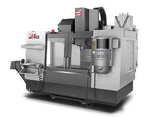
 立式加工中心
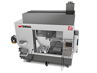 多轴解决方案
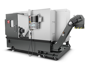 车削中心
车削中心
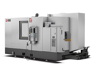 卧式加工中心
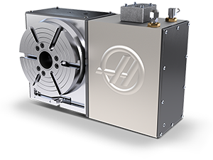 转台和分度器
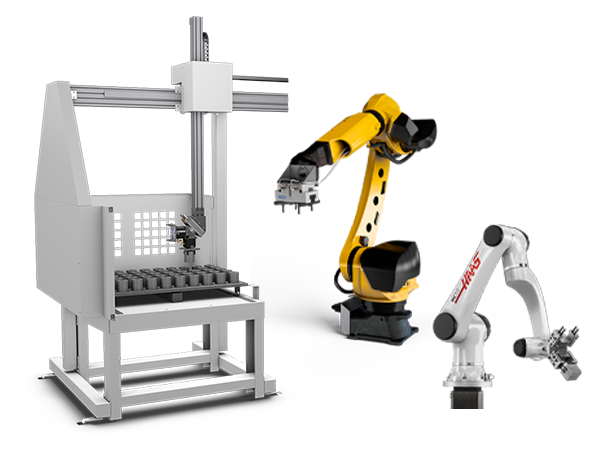 自动化系统
自动化系统
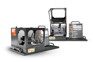 桌面机床
桌面机床
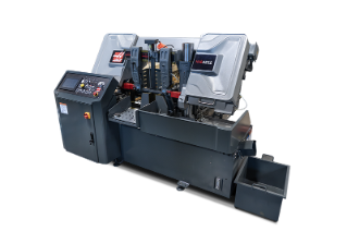 车间设备
车间设备
 主轴
主轴
 刀库
刀库
 第 4 轴 |第 5 轴
 刀塔和动力刀
 探测
探测
 切屑和冷却液管理
 Haas 控制系统
 产品选项
产品选项
 刀具和夹具
刀具和夹具
 工件夹具
工件夹具
 5 轴解决方案
 自动化
自动化

本节概述了 DC 系列机床的通电过程和回原点过程。
在为机床通电之前,请遵循安装章节中的空气和电气安装信息。验证这些步骤后,按下 Haas 控制器上的 [POWER ON] 按钮即可为机床供电。留出时间启动机床。
DC 系列机床无需在刀具恢复过程之外回原点。即使机器刚刚通电,这些机床也知道其定位。
Z 轴和刀塔 (TT) 轴的原点位置可由操作员设置。该过程通过换刀装置恢复来完成。有关如何恢复的说明,请参阅第 5.3 节“DC 系列换刀装置恢复”。
注意: 如果尚未设置所有轴的原点位置,则在尝试将轴返回到其原点位置之前,请参阅第 5.3 节。
如果所有轴都设置了原点位置,则可以将 X、Y 和 Z 轴移动到其原点位置。在 Haas 控制器上,使用以下命令将特定轴移动到其原点位置: {axis name}+[zero return]+[single]。
当机床收到警报 2066(换刀装置原点位置故障)时,您需要设置机床的原点位置。有关如何在 DC 系列机床上恢复换刀装置的帮助,请参阅第 5.3 节“DC 系列 - 换刀装置恢复”。
本节介绍如何将刀具装入刀库并操作换刀。要在主轴中装载刀具,必须首先将刀具装入刀库。
要在主轴中装载刀具,必须首先将刀具装入刀库。
重要信息:刀具无法直接装载到 DC-1 上的主轴中。

要装载刀具,请按 P{pocket_number} 以选择要装载刀具的刀套。然后按控制器上的 [ATC FWD] 以使刀库更换刀套位置。
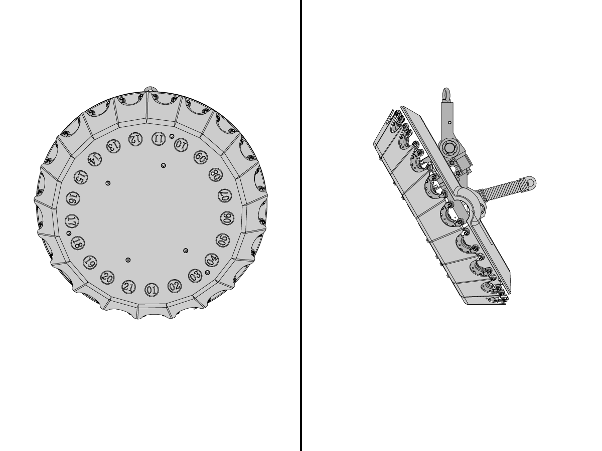
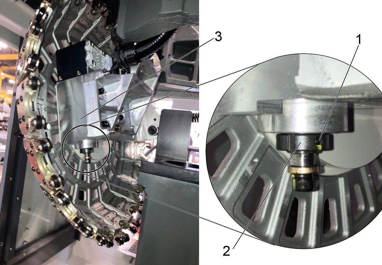
刀具只能装载到侧刀套中,如图 [1] 所示。在程序中调用 P 命令将使指定的刀套位于一侧。
示例: 调用 P6,然后 ATC FWD 将刀套 6 带到侧面,如图所示。
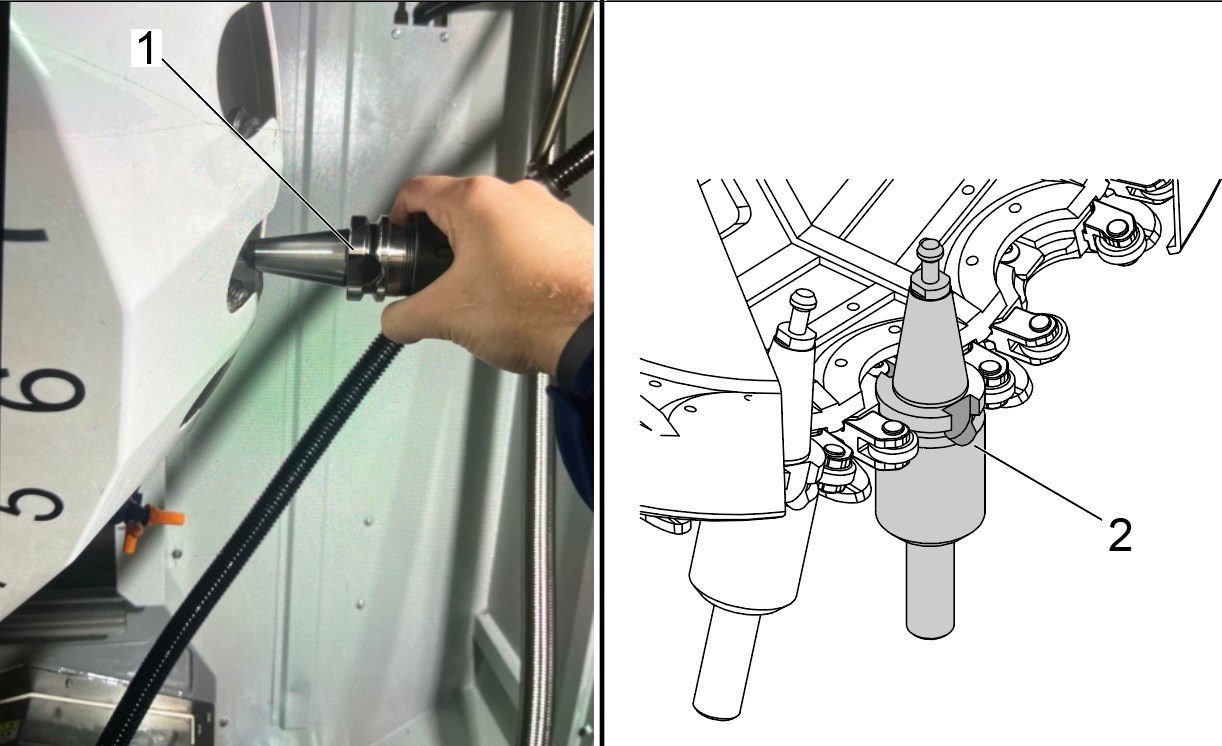
将刀具装入侧刀套时,请确保刀具的切口 [1] 朝向刀库的前部。此朝向让刀具能够正确装载到主轴中
注意:正确的刀具朝向如图 [2] 所示

刀具只能装入右侧刀套 [1]。此刀套有空间将刀具滑入到位。调整好刀具朝向后,将刀具拉向前门,将刀具锁定在刀套中
要更换刀具,必须有一个空的刀套与主轴对齐。此刀套将由当前加工刀具填充。按 T{pocket_number} 选择您希望机床更换的刀具。然后按控制器上的 [ATC FWD] 以执行程序。
立柱将沿 Z 轴向上移动,释放刀具,刀库将使指定刀具与主轴对齐。立柱将返回其 Z 轴零点位置,这将把刀具从刀套转移到主轴内。
DC 系列机床只能通过换刀装置恢复页面回原点。警报 2066(换刀装置原点位置故障)是需要恢复换刀装置的最常见指标。以下过程详细介绍了如何执行换刀恢复过程。此过程还介绍如何设置刀库和 z 轴的对齐值。
To do a complete reset of the TT-axis and Z-axis zero positions start by setting each of the following parameters and settings to the corresponding value:
Note: A service key is required to change these parameters and settings.
Note: Only reset these values if you are going to do a complete reset of the TT-axis zero position, and the Z-axis zero positions. If only basic recovery is needed, go through the automatic recovery steps in the Tool Changer Recovery page.
Note: Parameter 71, Drawbar Offset, and parameter 3.078, Z-axis Tool Change Offset shouldn't need to be changed and are not set through this procedure. All other offset values will be set to correct values through the process below.
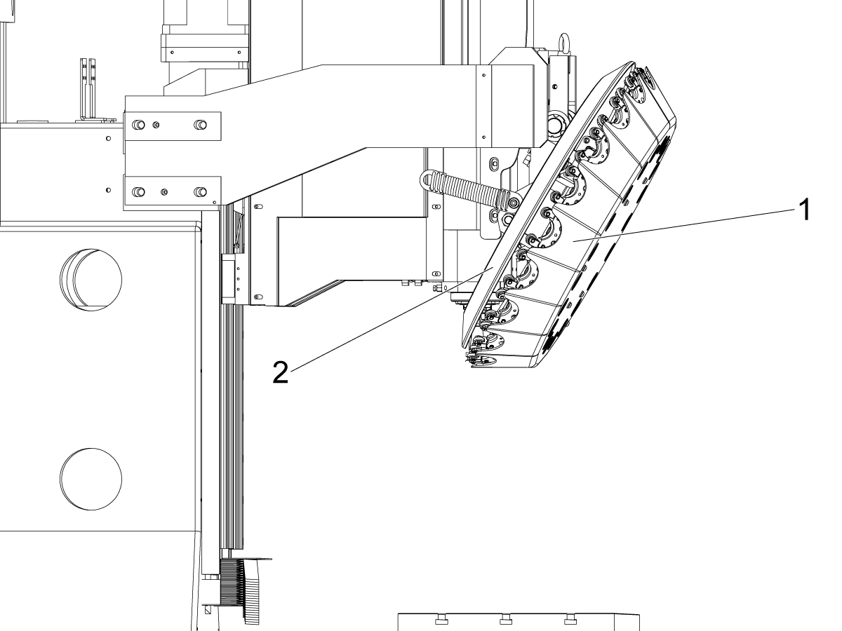
Before starting recovery, remove the front [1] and rear [2] covers of the tool carousel.
When unfastening these, verify that there is a mark on tool pocket 1, so you can keep track of which tool pocket is which.
警报 2066(换刀装置原点位置故障)表示刀库或 Z 轴需要回原点。这些轴必须手动操作,以设置回原点。
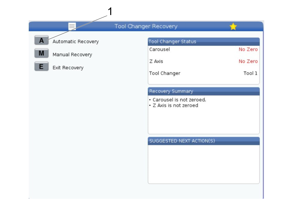
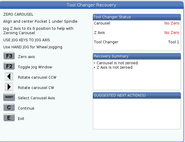
进入恢复页面时,您将被定向到图中所示的主页。选择 [A] 以自动恢复 [1]。

When asked in recovery, “Are there any tools present?” Either press yes [Y] or no [N] depending on if you have any tools in the carousel or spindle.
Note: it’s recommended to do this process without tools in the carousel/spindle if possible.
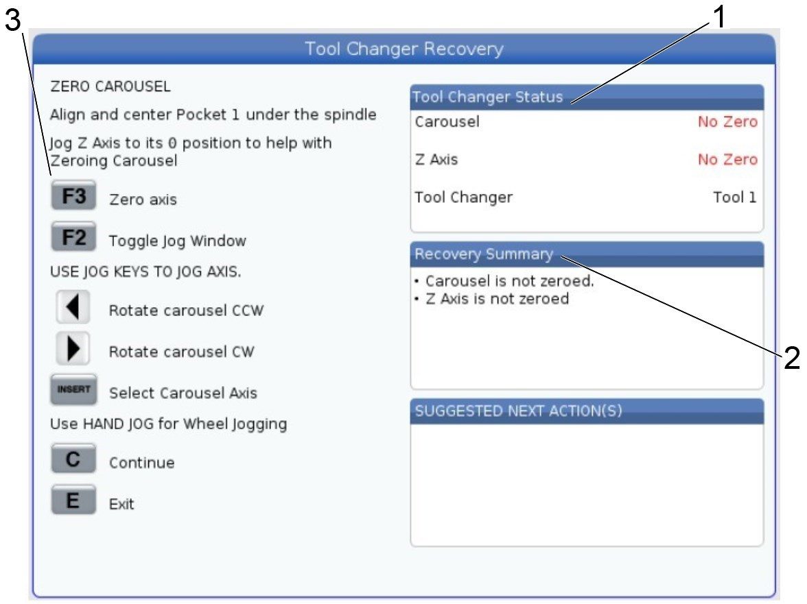
在“Automatic Recovery(自动恢复)”页面,您可以看到“Tool Changer Status(换刀装置状态)”[1] 、“Recovery Summary(恢复摘要)”[2] 以及用于完成恢复流程的键列表 [3]。
刀库可以通过箭头键或按 [TT]+ 手轮点动来点动。
同样,可通过按 [Z]+手轮点动来点动 Z 轴。
说明:刀库只能在恢复模式下点动。
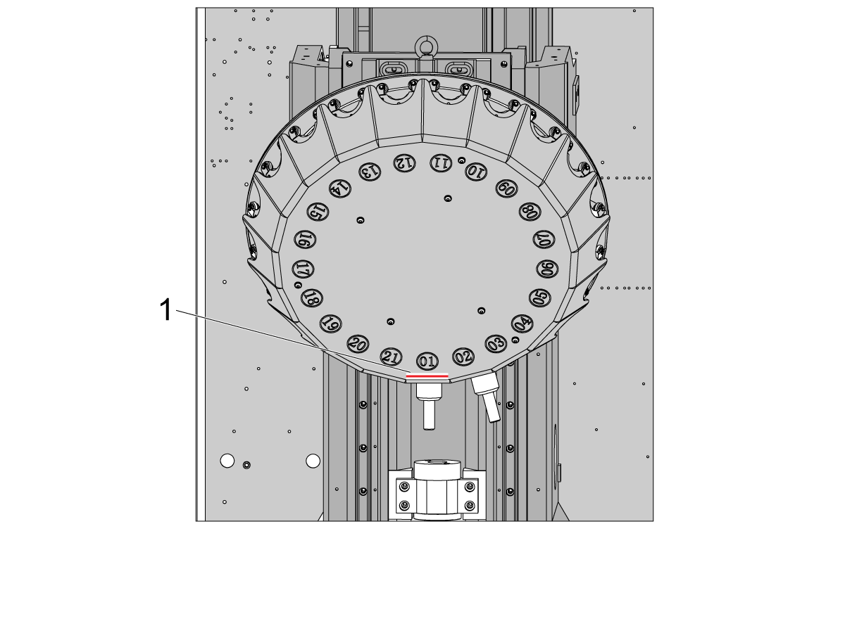
要将刀库回原点,请将刀库的刀套 1 对准更换位置,并将其调平,使刀套 1 [1] 的底部水平。如果刀套 1 正确对齐,则固定刀具的手指将与主轴对齐。
刀套对齐后,按 [F2] 切换到恢复页面。在恢复页面上按 [F3] ,刀库将在刀套 1 上回原点。
注意: 该图显示了装载在刀库中的刀具,但同样的流程也适用于未装载刀具的情况。
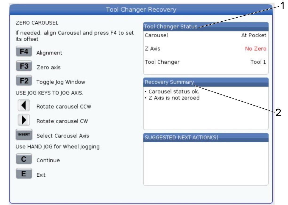
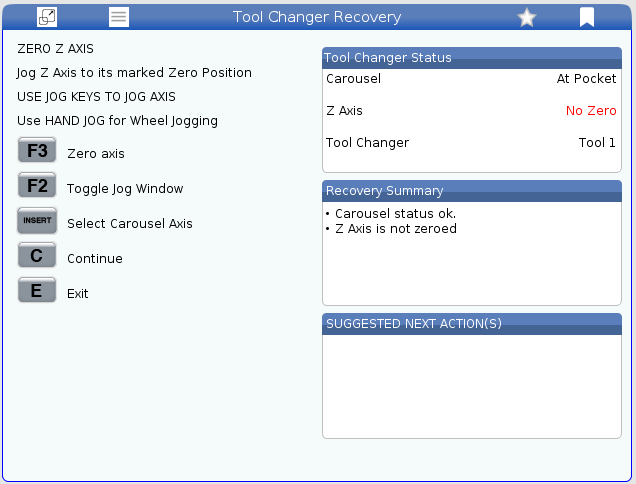
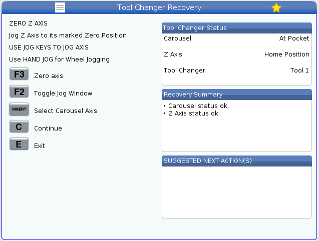
当已设置刀库的回原点位置时,恢复页面将如下所示。Tool Changer Status [1](换刀装置状态 [1])部分将列出“Tool 1(刀具 1)”,以及转盘是否为“At Pocket(在刀套)”。Recovery Summary [2](恢复摘要 [2])部分还将显示一条消息,以表明刀库处于可接受的状态。
按 [F4] 以设置刀库与刀套 1 的对齐方式,使刀库与主轴对齐。当您在控件上看到“Settings Applied(已应用设置)”消息 时,则已设置偏置值。
重要提示:使用 [F4] 设置偏置后, 恢复页面可能会显示刀库需要再次回原点。当刀库处于已设置对齐时的相同位置时, 按 [F3] 使轴回原点。
说明:Z 轴仍需手动回原点。这在以下步骤中详细说明。

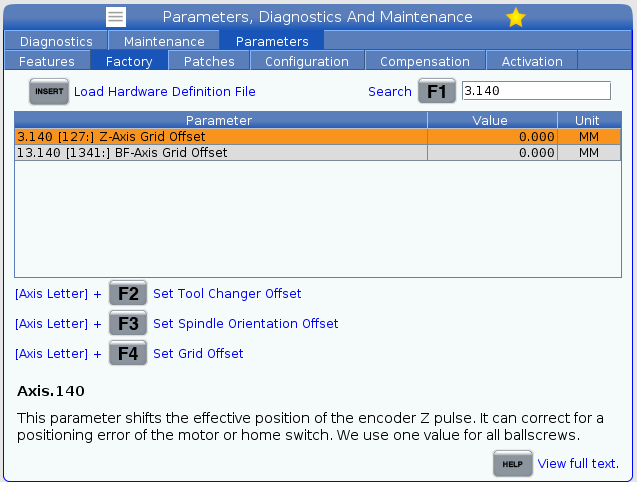
You now need to exit recovery to set the TT-axis grid offset parameter P9.140. Press [E] twice to exit recovery.
Then navigate to the 'factory settings' tab on the pendant.
Search for TT-axis Grid Offset (9.140).
Press [TT]+[F4] to set the parameter value. A popup will display and you will need to press [Y] to confirm.
The value for the parameter should now be set at this point.
Note: The value shown in the image below is 0, but an actual value should get set.
Return to the recovery window by pressing [Recover].
Answer all the prompted questions until you get to the screen shown in the image.
The Carousel will say No Zero. The zero position needs to be set again.
Press [F2] to switch to jog mode, and then jog the TT-axis so that pocket 1 is center on the spindle. Then press [F3] to re-zero the TT-axis.
Note: This is the same as step 6.

After the zero position is set for the carousel, the TT-axis Tool Change Offset (P9.078) needs to be set. Exit recovery by pressing [E] twice.
Go to the 'Positions' tab and press [Alter] and check the TT-axis to make it visible.
Place a mag base with an indicator on the table and indicate the face of pocket 1 along the X-axis. This is to make sure that pocket is sitting flat.
Jog the TT-axis until the face of the pocket from point [1] to point [2] is 0.0005" NTE.

Jog the Z-axis up so that a tool can be placed in pocket 1. Place a tool in the pocket.
Jog the Z-axis down and verify the Z-Axis is not forcing the carousel to rotate as it engages the tool in pocket 1.
Use a mirror and light to view shown in the image.
You want to make sure that there is equal space on each side of the spindle drive dogs. Jog the TT-axis until the gap on the left side [1] and right side [2] of the spindle dog are even.
Note: This image shows uneven gaps between [1] and [2]. This means the tool carousel should be jogged until the gap is even.
Once you have the correct position, navigate to the 'Factory Settings' tab and search for parameter 9.078 (Tool Turret Tool Change Offset).
To set the parameter value press [TT]+[F2] and then confirm by pressing [Y].
The parameter 9.078 should now be set.
Remove the tool from pocket 1.

After both the TT-axis Grid Offset and TT-axis Zero Return Offset have been set, the zero position needs to be reset.
Go into recovery by pressing the [Recover] button. Then after answering the questions press [F3] to set the zero position for the TT-axis.
Note: The tool carousel should not have to be moved from the previous step.
When F3 is pressed the carousel should move slightly and then return to it's zero position.
The tool changer status window should show 'At Pocket' and 'Tool 1'. Press [C] to continue to setting the Z-axis offsets.

在控件上按 [F2] 以切换到点动模式。然后按 [Z]+[Handle Jog] 以沿 Z 轴点动主轴。点动轴,直到将立柱 [1] 上的标贴与护罩内部的标贴 [2] 大致对齐。对齐后,按 [F2] 返回恢复页面,然后按 [F3] 使 Z 轴回原点。
注意: 按下 [F3] 时,Z 轴将稍微移动。这是流程中此时的正常行为。
Z 轴和刀库对齐并回原点后,“Tool Changer Status(换刀装置状态)”部分将类似于图像 [1]。
完成后,恢复菜单将提示您按 [C] 以 25% 的速度执行换刀以验证对齐情况。
注意: 建议选择此选项,尤其是首次执行恢复过程时。
如果不需要测试换刀,请按 [E] 以退出换刀装置恢复页面。
Go back into recovery now by pressing the [Recover] button. Once in recovery page, the 'tool changer status' window will read "No Zero" for the Z-axis.
The Z-axis zero position needs to be set.
Repeat step 14 so that the arrow decals are lined up as best as possible.
Press [F3] to set the zero position for the Z-axis.
Once the zero position is set, the Z-axis Zero Return Offset (3.367) parameter can be set.
Press [E] twice to exit recovery.
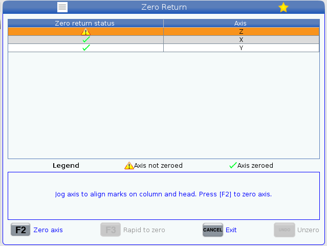
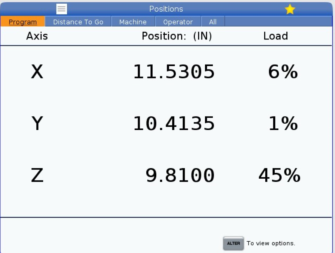
Press [Z]+[Zero Return]+[Single] to bring up the page shown in the image.
Highlight the Z row and press [Undo] to unzero the axis.
Press [Cancel] to exit that page.
Note: The Z-axis cannot be jogged in the positive direction passed 0. That is why we have to clear the zero position.
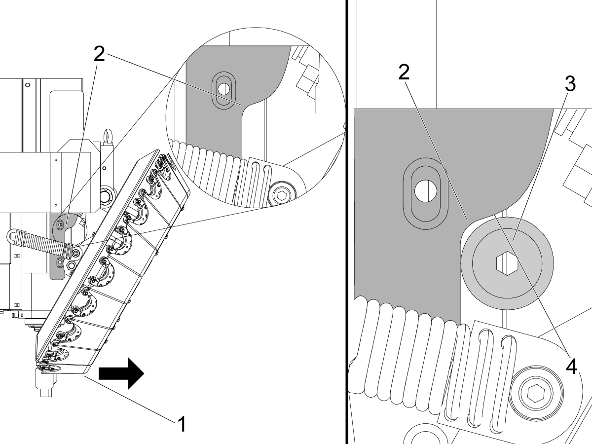
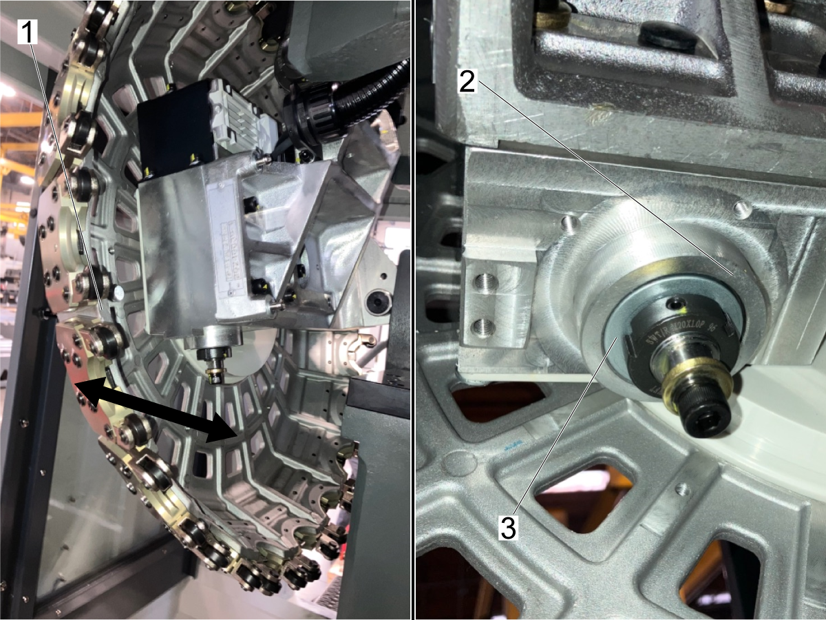
Jog the Z-axis up until the roller [3] on the tool changer body is sitting in the radius [2] on the guide rail [4] on the left side of the spindle head.
Note: It's difficult to see the position of the roller on the guide rail. This image shows the roller disconnected from the tool carousel which is only to clearly show the roller. You will know you are passed the radius [2] when the tool carousel stops moving back toward the spindle.
Place you hand on the front [1] of the tool carousel when jogging the Z-axis. Once you feel the tool carousel no longer pull towards the spindle stop jogging.
The roller [1] will now be in the positioned right on the radius.
Slide a 0.002" shim [2] in between the roller and the guide rail [3].
If the shim can't fit under jog the Z-axis down slightly to move the roller up on the radius.
Once the shim is able to slide in between, jog the Z-axis up so that it is difficult to pull the shim out from under the roller.
Note: This step is important for setting the Z-axis zero position. If this position is not set in the correct spot then tool changes may be excessively loud.
Once it is difficult to pull the shim out, remove the shim.
Then jog the Z-axis down 0.002" to account for the shim size.
Press [Position] and then go to 'machine position' and record the value for the Z-axis
Use that value to do the following calculation:
12mm - {recorded value} = Z-axis Zero Return Offset
Note: The 12mm is the Drawbar Offset parameter.
Go to ‘factory settings’ tab and search for parameter 3.367 Z-axis Zero Return Offset.
Set this parameter to the value calculated in the previous step.
Note: The Z-axis zero return offset should be a negative value. If it isn't, verify the calculation was done correctly.
At this point the following parameters should be set:
Go into Recovery by pressing [Recover] and then continue to automatic recovery.
Press [F2] to toggle to jog mode and then jog the Z-axis so that the arrow decals are aligned as best as possible.
Note: Reference step 14 for more details.
After the arrows are aligned, press [F3] to set the zero position for the Z-axis.
The 'tool changer status' and 'recovery summary' should be the same as the image. Press [C] to continue and then continue to doing a test tool change at 25% rapid.
本节介绍如何对 DC-1 刀库中发现的常见问题进行故障排除。
| 症状 | 可能的原因: | 纠正措施 |
| 换刀装置旋转时,刀库发出磨削/嗡嗡声 | 换刀装置轴上的锁紧螺母拧得太紧 | 松开固定螺栓,以减少刀库旋转时的噪音。确保锁紧螺母足够紧,以使刀库体锁定到位。请查看下列说明,以了解如何松开锁紧螺母。 |
| 执行换刀时,当 Z 轴接合刀具时,会发出响亮的沉闷声 | Z 轴原点位置未设置在正确位置 | 强制机床进入 Z 轴的恢复状态。要强制恢复,请将 Z 轴网格偏移 (3.140) 设置为 1,然后将其设置回 0,然后将 Z 轴回原点偏移 (3.367) 设置为 0。 然后进入换刀恢复以重置 Z 轴原点位置。请参阅以下部分,了解 Z 原点位置应该在哪里。 |
如果旋转到其他刀套时刀库发出响亮的磨削声音,则换刀装置轴上的锁紧螺母太紧。要消除磨削噪音,请按照以下步骤松开锁紧螺母。
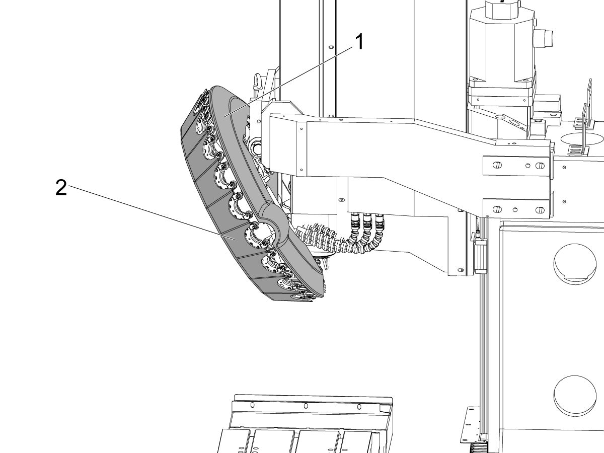
拆下刀库的后盖 [1] 和前盖 [2],以露出将刀库固定到位的锁紧螺母。
松开 3 个将锁紧螺母 [2] 固定到换刀装置 [3] 轴上的固定螺栓 [1]。
固定螺栓不必完全拆下,只需后退,这样就不会压在轴上。
说明:锁紧螺母有 3 个键槽,方便拧紧或松开锁紧螺母。

松开固定螺栓后,逆时针旋转锁紧螺母 [1],以松开轴上的锁紧螺母。
将锁紧螺母旋转 1/8 - 1/4 圈。
拧紧 3 个固定螺栓 [2] 以将锁紧螺母固定到位。确保固定螺栓均匀拧紧。
确保锁紧螺母足够紧,以防止换刀装置错位。
拉动刀库 [1] 的一端,并查找换刀装置体 [2] 和轴 [3] 的角度对齐方式。
如果刀库通过拉动或推动刀库的一侧失去对齐,则将已旋松的锁紧螺母拧紧一半。
如果拉动刀库无法实现对齐,则再次运行换刀装置以检查噪音是否仍然存在。
如果在松开锁紧螺母后仍有磨削噪音,请重复步骤 2-4,并不断逐渐松开锁紧螺母。
如果松开锁紧螺母不会降低刀库旋转时的磨削声音,请联系 Haas service。
Z 轴原点位置是执行换刀之前 Z 轴回到的点。
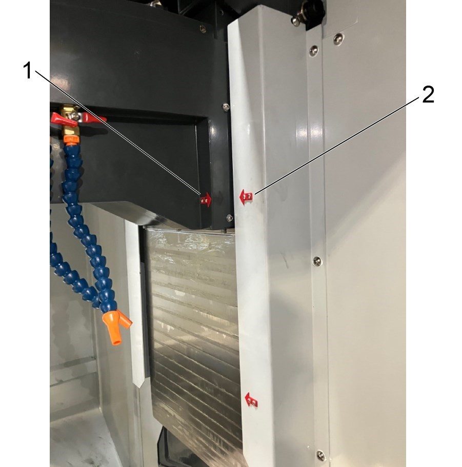
说明:Z 轴回原点位置应大致位于立柱 [1] 上的箭头标贴与护罩 [2] 上的箭头标贴对齐时的位置。
这些箭头给出了一个粗糙的位置。如果原点位置已设置为这些标贴对齐的位置,但换刀装置声音过大,则需要更精确地设置原点位置。
Z 轴原点位置可通过换刀装置恢复过程重置。要强制恢复 Z 轴,请更改以下参数:
更改这些参数后,通过按 Haas 控件上的 [RECOVER] 进入换刀装置恢复页面。
Z 轴需要设置原点位置。
将 Z 轴旋转到换刀装置的底部边缘 [1] 开始朝机床的前部移动时的位置。
换刀装置开始向前推时的位置即滚轮开始击中换刀装置左侧锐半径 [2] 时的位置。
然后将 Z 轴向上点动 0.050" (1.27 mm),以便在轴承 [3] 和锐半径 [2] 的上部之间有间隙 [4]。
说明:右图显示了点动 Z 轴 0.050" (1.27 mm) 时所需的间隙。
从这个位置。将 Z 轴向下点动 0.9055" (23 mm)。这将是 Z 轴回原点位置。
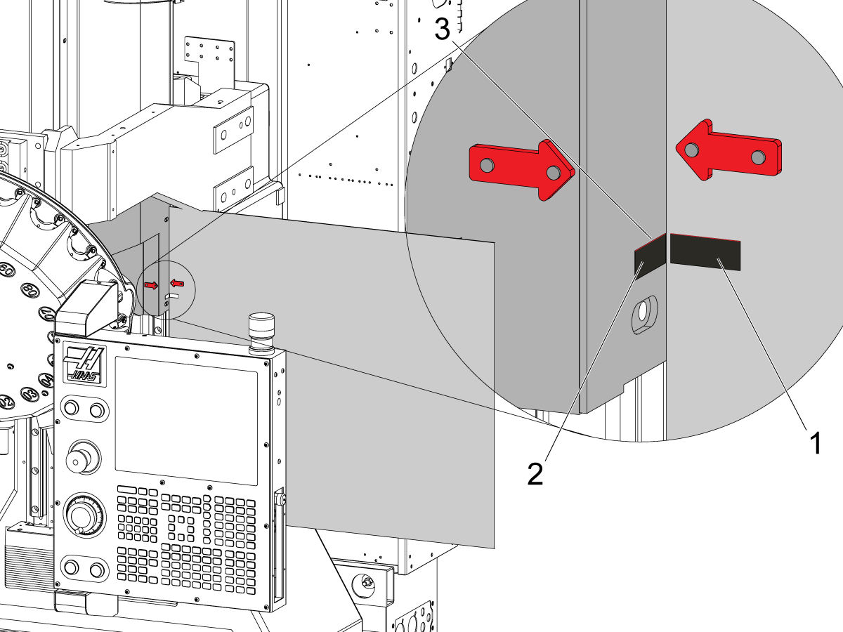
在后护板 [1] 上做一个标记,在立柱 [2] 上做一个标记,即使在箭头的尖端。
说明:这应该靠近后护板上的箭头所在位置。如果它不靠近箭头,请验证步骤 1 和 2 是否已正确完成。
这些标记用于更精确的位置,以设置 Z 轴回原点. 在图像中,将胶带 [3] 的上边缘用作对齐指引。
当在恢复页面上设置原点位置时。按 [F3]。Z 轴将下降。
如图所示,将 Z 轴向上点动到标记对齐的位置。
按 [C] 以继续下一个恢复步骤。
按 [F4]以设置对齐方式。
按 [F3] 以设置回原点位置。
继续完成恢复过程的其余部分。
如果新的 Z 轴原点位置导致换刀更安静。使这些标记更永久,以便将来更容易通过换刀装置恢复。
在换刀装置恢复程序中,应将标记视为红色箭头标贴。
Recently Viewed Items
You Have No Recently Viewed Items Yet

美元价格不包括关税、报关费用、保险费、增值税及运费。
USD prices DO NOT include customs duty, customs fees, insurance, VAT, or freight.
人民币价格包含关税、报关费用、货运保险和增值税, 但不包括运费。
CNY prices include customs duty, customs fees, insurance, and VAT. DOES NOT include freight.
此价格包含运费、出口和进口关税、保险费以及任何在运送至与您(买家)商定的位于法国的某一地点的过程中产生的其他费用。在 Haas 数控产品的交付中不会添加任何其他强制性费用。
随时掌握 HAAS 最新提示和技术……
HAAS TOOLING ACCEPTS THE FOLLOWING:


This site is protected by reCAPTCHA and the Google Privacy Policy and Terms of Service apply.

2800 Sturgis Rd., Oxnard, CA 93030 / Toll Free: 800-331-6746
Phone: 805-278-1800 / Fax: 805-278-2255