My Haas Welcome,
!
Haas Tooling MyHaas/HaasConnect Sign In Register Haas Tooling MyHaas/HaasConnect Sign Out Welcome, My Machines Latest Activity My Quotes My Account My Users Sign Out
Find Your Distributor
  1. Select Language
    1. English
    2. Deutsch
    3. Español - ES
    4. Español - MX
    5. Français
    6. Italiano
    7. Português
    8. Český
    9. Dansk
    10. Nederlands
    11. Magyar
    12. Polski
    13. Svenska
    14. Türkçe
    15. 中文
    16. Suomi
    17. Norsk
    18. الإنجليزية
    19. български
    20. Hrvatski
    21. Ελληνικά
    22. Română
    23. Slovenský
    24. Slovenščina
    25. 한국어
    26. 日本語
    27. Українська
  • machines Main Menu
    • Vertical Mills
      Vertical Mills
      Vertical Mills View All
      • Vertical Mills
      • VF Series
      • Universal Machines
      • VR Series
      • VP-5 Prismatic
      • Pallet-Changing VMCs
      • Mini Mills
      • Mold Machines
      • High-Speed Drill Centers
      • Drill/Tap/ Mill Series
      • Toolroom Mills
      • Pocket Mill
      • Compact Mills
      • Gantry Series
      • SR Sheet Routers
      • Extra-Large VMC
      • Double-Column Mills
      • 3+2 Positioning Machines
    • Multi-Axis Solutions
      Multi-Axis Solutions
      Multi-Axis Solutions View All
      • Multi-Axis Solutions
      • Y-Axis Lathes
      • 5-Axis Mills
    • Lathes
      Lathes
      Lathes View All
      • Lathes
      • ST Series
      • Dual-Spindle
      • Box Way Series
      • Toolroom Lathes
      • Chucker Lathe
      • Pocket Lathe
      • Haas Bar Feeders
    • Horizontal Mills
      Horizontal Mills
      Horizontal Mills View All
      • Horizontal Mills
      • 50-Taper
      • 40-Taper
    • Rotaries & Indexers
      Rotaries & Indexers
      Rotaries & Indexers View All
      • Rotaries & Indexers
      • Rotary Tables
      • Indexers
      • 5-Axis Rotaries
      • Extra-Large Rotaries
    • Special Series
      Special Series
      Special Series View All
      • Special Series
      • EU_Series_Redirect
    • Automation Systems
      Automation Systems
      Automation Systems View All
      • Automation Systems
      • Mill Automation
      • Lathe Automation
      • Automatic Parts Loaders
      • Automation Models
    • Desktop Machines
      Desktop Machines
      Desktop Machines View All
      • Desktop Machines
      • Desktop Mill
      • Desktop Lathe
      • Control Simulator, Standard
      • Control Simulator, Premium
    • Shop Equipment
      Shop Equipment
      Shop Equipment View All
      • Shop Equipment
      • Knee Mill
      • Haas Manual Lathes
      • Haas Saws
    • Fabrication Machines
      Fabrication Machines
      Fabrication Machines View All
      • Fabrication Machines
      • Laser Cutting Machines
      • CNC Press Brakes
    • QUICK LINKS Special Series  Special Series 
      EU SERIES EU SERIES BUILD & PRICE | PRICE LIST BUILD & PRICE | PRICE LIST In-Stock Machines In-Stock Machines WHAT’S NEW WHAT’S NEW YOUR FIRST CNC YOUR FIRST CNC
      SHOPPING TOOLS
      • Build & Price a Haas
      • Price List
      • Available Inventory
      • CNCA Financing
      WANT TO TALK TO SOMEONE?

      A Haas Factory Outlet (HFO) can answer your questions, and walk you through your best options.

      CONTACT YOUR DISTRIBUTOR >
  • Options Main Menu
    • The Haas Control Value Option Packages
      Value Option Packages
      Value Option Packages View All
      • Value Option Packages
    • Product Image Spindles
      Spindles
      Spindles View All
      • Spindles
    • Product Image Tool Changers
      Tool Changers
      Tool Changers View All
      • Tool Changers
    • Product Image 4th- | 5th-Axis
      4th- | 5th-Axis
      4th- | 5th-Axis View All
      • 4th- | 5th-Axis
    • Product Image Turrets & Live Tooling
      Turrets & Live Tooling
      Turrets & Live Tooling View All
      • Turrets & Live Tooling
    • Product Image Probing
      Probing
      Probing View All
      • Probing
    • Haas Chip & Coolant Management Chip & Coolant Management
      Chip & Coolant Management
      Chip & Coolant Management View All
      • Chip & Coolant Management
    • The Haas Control The Haas Control
      The Haas Control
      The Haas Control View All
      • The Haas Control
    • Product Image Product Options
      Product Options
      Product Options View All
      • Product Options
    • Product Image Tooling & Fixturing
      Tooling & Fixturing
      Tooling & Fixturing View All
      • Tooling & Fixturing
    • Product Image Workholding
      Workholding
      Workholding View All
      • Workholding
    • Product Image 5-Axis Solutions
      5-Axis Solutions
      5-Axis Solutions View All
      • 5-Axis Solutions
      • 5 Easy Steps to 5-Axis
    • QUICK LINKS Special Series  Special Series 
      EU SERIES EU SERIES BUILD & PRICE | PRICE LIST BUILD & PRICE | PRICE LIST In-Stock Machines In-Stock Machines WHAT’S NEW WHAT’S NEW YOUR FIRST CNC YOUR FIRST CNC
      SHOPPING TOOLS
      • Build & Price a Haas
      • Price List
      • Available Inventory
      • CNCA Financing
      WANT TO TALK TO SOMEONE?

      A Haas Factory Outlet (HFO) can answer your questions, and walk you through your best options.

      CONTACT YOUR DISTRIBUTOR >
  • Why Haas Main Menu
      Discover the Haas Difference
    • Why Haas
    • MyHaas
    • Education Community
    • Industry 4.0
    • Haas Certification
    • Customer Testimonials
  • Service Main Menu
      Welcome to Haas Service
      SERVICE HOME Operator’s Manuals How-To Procedures Troubleshooting Guides Preventive Maintenance Haas Parts Haas Tooling Videos
  • Videos Main Menu
  • Main Menu
    • View All
    • View All
    • View All
    • View All
      • HTEC Curriculum Support
      • Haas Value Option Packages (VOP) Journey
    • View All
      • Haas 10 kg Cobot Package
      • Cobot Kits
      • DC-1 Drill Center
      • CNC Sales News
      • Do More With Your Haas
    • View All
    • View All
      • contact-us-test
      • 4 - AUTOMATION SYSTEMS
      • Carousel-V2
      • expert test
      • Demo_Day_Trident-test
      • Link Test
      • image-sale-tag-test
      • article-list-test
      • Haas 25 kg Robot Package
      • test-algolia-page
    • View All
    • View All
    • View All
    • View All
      • calc-test
    • View All
    • QUICK LINKS Special Series  Special Series 
      EU SERIES EU SERIES BUILD & PRICE | PRICE LIST BUILD & PRICE | PRICE LIST In-Stock Machines In-Stock Machines WHAT’S NEW WHAT’S NEW YOUR FIRST CNC YOUR FIRST CNC
      SHOPPING TOOLS
      • Build & Price a Haas
      • Price List
      • Available Inventory
      • CNCA Financing
      WANT TO TALK TO SOMEONE?

      A Haas Factory Outlet (HFO) can answer your questions, and walk you through your best options.

      CONTACT YOUR DISTRIBUTOR >
  • Haas Tooling Main Menu
  • Haas Service Parts Main Menu

My Haas Welcome,
!
Haas Tooling MyHaas/HaasConnect Sign In Register Haas Tooling MyHaas/HaasConnect Sign Out Welcome, My Machines Latest Activity My Quotes My Account My Users Sign Out
Find Your Distributor
  1. Select Language
    1. English
    2. Deutsch
    3. Español - ES
    4. Español - MX
    5. Français
    6. Italiano
    7. Português
    8. Český
    9. Dansk
    10. Nederlands
    11. Magyar
    12. Polski
    13. Svenska
    14. Türkçe
    15. 中文
    16. Suomi
    17. Norsk
    18. الإنجليزية
    19. български
    20. Hrvatski
    21. Ελληνικά
    22. Română
    23. Slovenský
    24. Slovenščina
    25. 한국어
    26. 日本語
    27. Українська
×

Search Results

Web Pages

Images

    • <
    • 1
    • >

2 - Haas Air Compressor - Installation

Haas Air Compressor - Operators/Service Manual


  • 0 - Haas Air Compressor - Table of Contents
  • 1 - Haas Air Compressor - Introduction
  • 2 - Haas Air Compressor - Installation
  • 3 - Haas Air Compressor - Operation
  • 4 - Haas Air Compressor - Maintenance
  • 5 - Haas Air Compressor - Troubleshooting

Go To :

  • 2.1 HAC15-FS/VS Installation
  • 2.2 HAC30-VS Installation

2.1 HAC15-Fixed Speed/Variable Speed Installation

Overview

This chapter of the manual provides details about how to install the Haas Air Compressor - 15HP. This chapter gives information about pre-installation precautions, installation requirements, and electrical installation requirements for both the fixed speed and variable speed versions.

Air Compressor Pre-Installation

1

When storing the air compressor pre-installation, the compressor should be placed in a dry area that has a typical ambient temperature between 41-112 degrees Fahrenheit

2

The single speed and variable speed air compressors have the same physical footprint and weight. Refer to section 1.2 to see the specifications of the compressors. The compressors weigh approximately 1015 lbs. 

3

Move the air compressor as close to it's installation location as possible before removing the compressor from the protective packaging. To make it easier to move the compressor, leave it secured to the pallet.

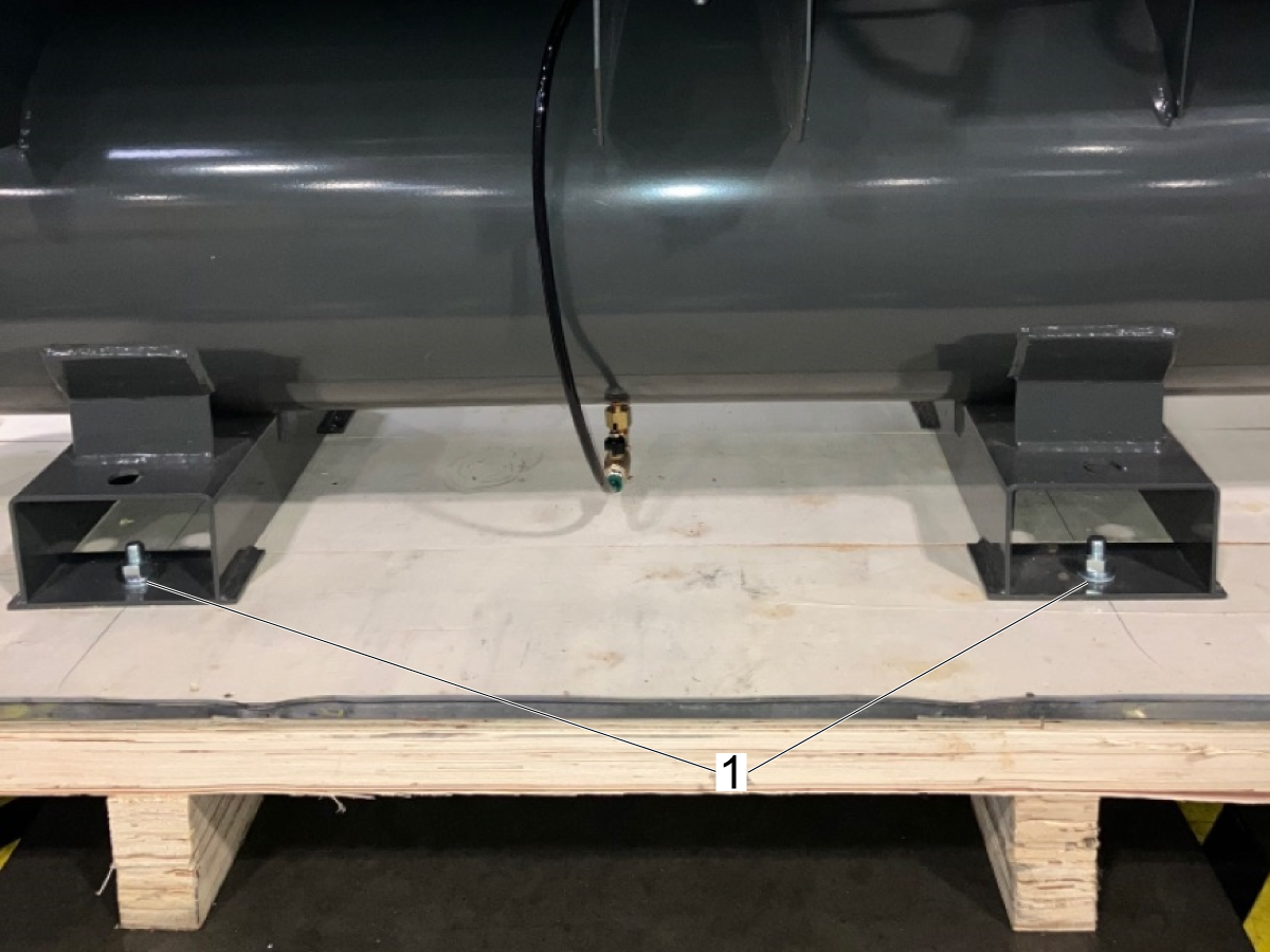
When ready to install the compressor, unfasten the feet from the pallet. Each foot connected to the storage tank has a bolt [1] fastened to the pallet as shown in the image.

Air Compressor Installation

1

Once the feet have been unfastened from the pallet, use the forklift to move the compressor to it's installation location. The installation location should adhere to the following specifications:

  • The ambient temperature where the air compressor will operate should be between 41-112 Fahrenheit (5-45 Celsius).
  • The compressor should be operated in a brightly lit area for the operators safety.
  • The air compressor should not be installed in an area that has a high risk of fire.
  • The compressor must be installed in a well ventilated area that has a large supply of dust-free air. If the air quality is low, the air filter may need to be cleaned or replaced more frequently than what is listed in the maintenance chapter of this manual.

Important: It is recommended to use the compressor indoors. If there is outdoor space that is well protected from rain or extreme elements, the air compressor can be installed in an outdoor location.

Warning: Exposure to the elements can cause damage to components or an increased frequency of maintenance required.

 Note: The performance of the compressor may decrease in conditions with high ambient temperature and humidity above 80% or at an elevation higher than 3,200 feet.

2

Make sure that the compressor is installed onto a roughly leveled surface. The compressor should not be installed onto an angled surface since the air compressor is not anchored to the floor.

3

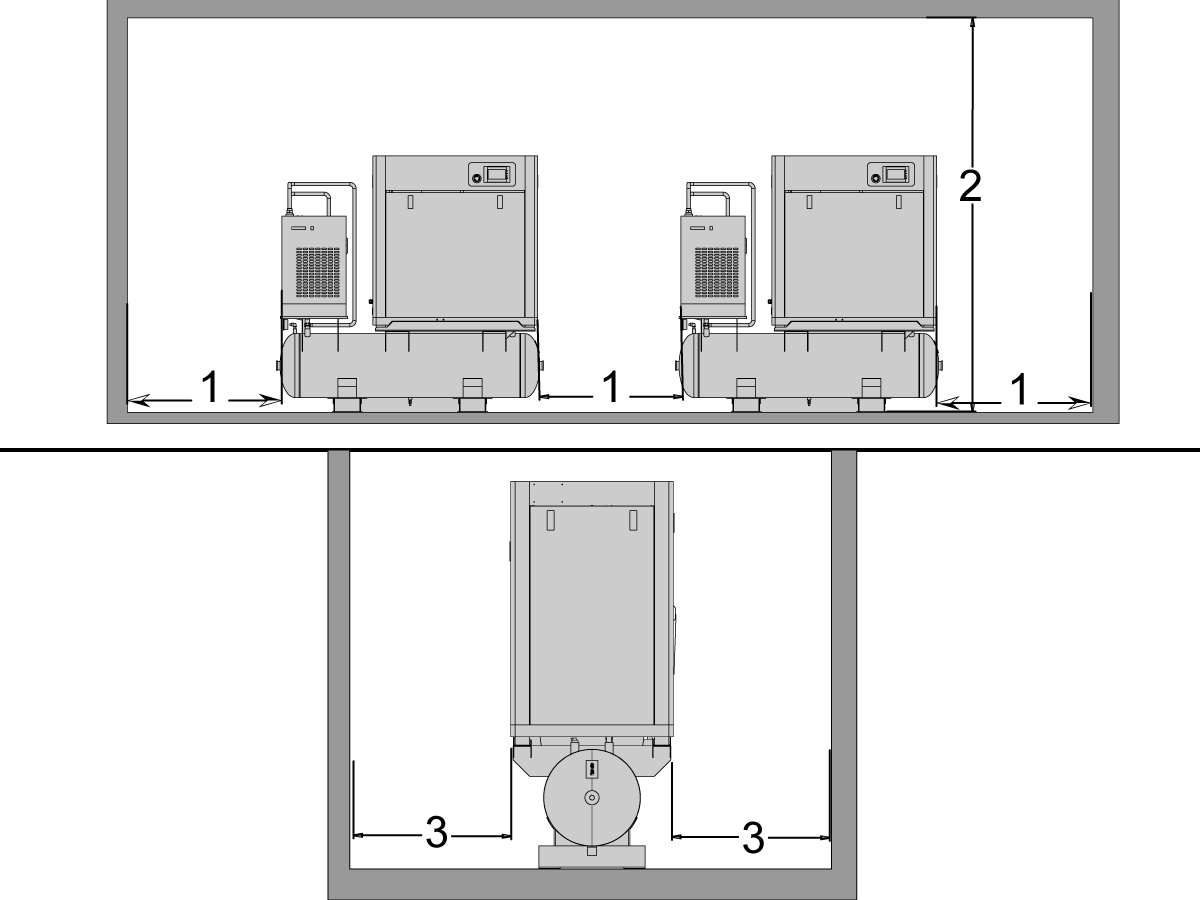
The image shows the recommended ventilation and minimum spacing requirements needed for a compressor to run efficiently.

  • At least 3 ft (1 meter) [1] spacing between compressors and between the sides of the compressors and any walls as shown in the image.
  • The compressor needs to be in an area with a ceiling clearance of at least 8.2 ft (2.5 meters) [2].
  • At least 3 ft (1 meter) [3] of spacing from any walls in the front or back of the compressor so that it can be easily serviced.

4

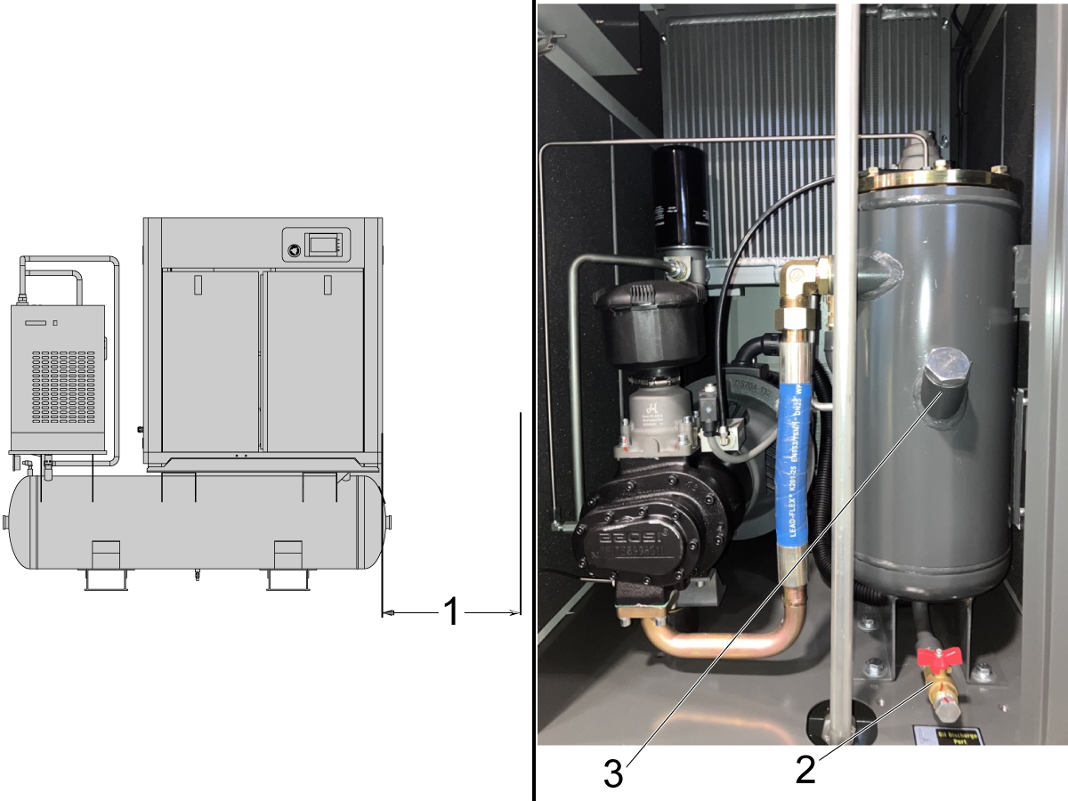
When determining the location of the compressor, there needs to be at least 3 ft (1m) of open space on the right side [1] of the compressor.

Note: This is so that the oil discharge port [2] and oil intake [3] can be easily accessed when performing oil changes.

 Important: The air compressor will come with oil inside the oil reservoir. The oil that is supplied with the air compressor is for the first maintenance oil change. The compressor does not need to be filled with oil at install.

5

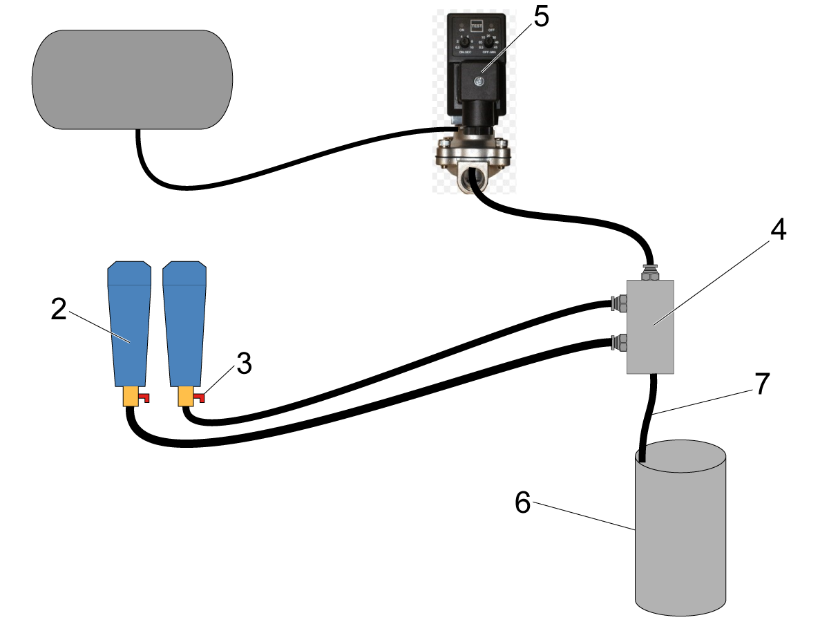
Route the black airlines [1] connected to the oil-water separators [2] to a discharge container [6].

Important: The red ball valves [3] located on the oil-water separators need to be manually opened weekly to drain the water. The drain valves need to be fully closed when the air compressor is being used.

Route the airlines coming from the separators to the manifold [4] that is connected to the timer valve [5]. Route the output line [7] of the manifold to a discharge container [6]. See section 3.1 Operation for details on configuring the timer drain.

6

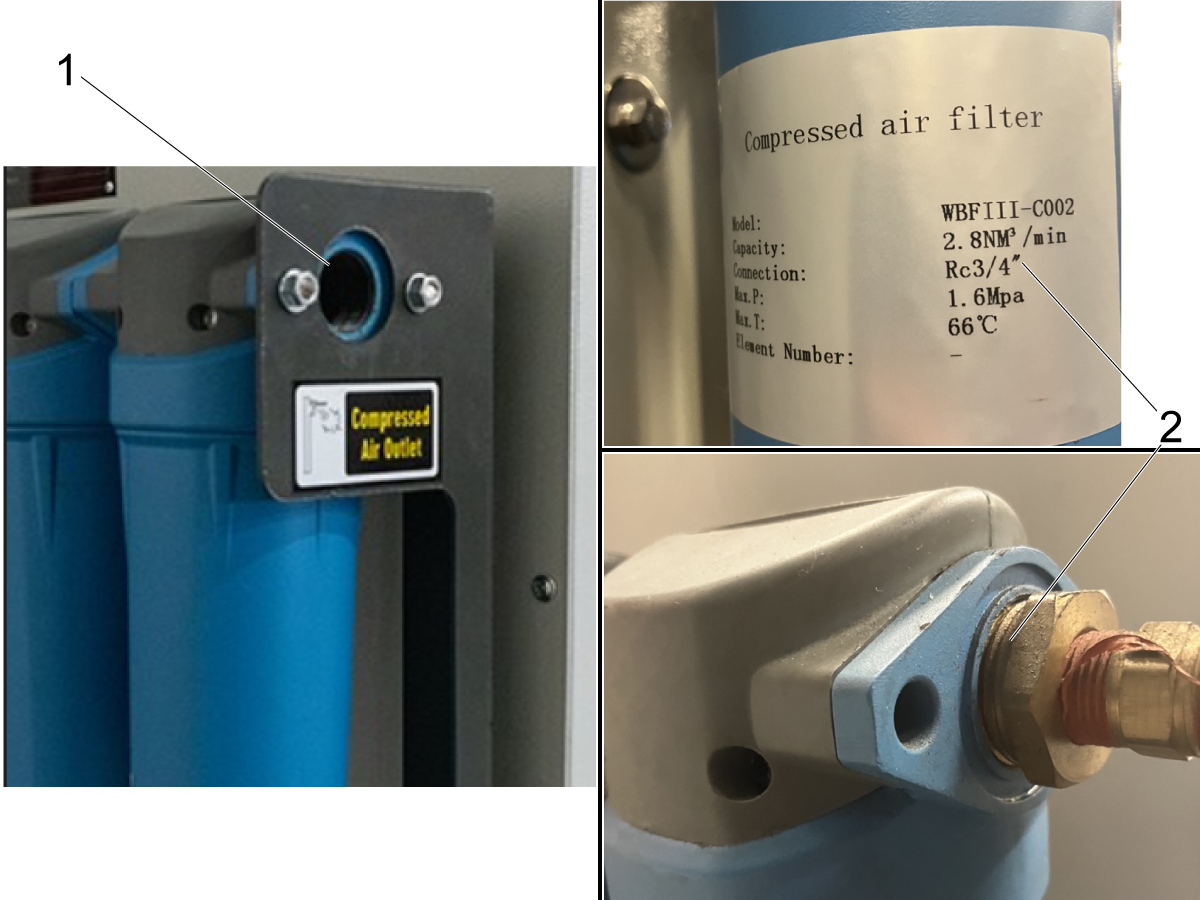
Connect an airline to the outlet of the compressed air filter [1] shown in the image.

Note: The thread for the male fitting needed to connect the airline to the filter is defined on the label on the filter cannister [2].

The thread type for HAC15-FS and HAC15-VS compressors is an RC-3/4" thread [2].

Air Compressor - Electrical Installation

1

Warning: The compressor must have a ground connection when connecting it to the power supply. Connecting the compressor to the power supply is dangerous and should be done by qualified personnel only.

To connect the air compressor to power, make sure that the appropriate power supply is being used.

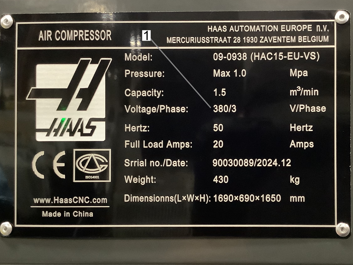
Verify that the incoming voltage meets the electrical specifications for the air compressor listed on the specification plate. Compressors can be 220VAC / 3Phase or 380VAC / 3Phase.

Note: The specification plate shown in the image is for 380 VAC [1] since it is the European version. Compressors in the United States are made for 220 VAC but check the specification plate to confirm before you connect the incoming power.

2

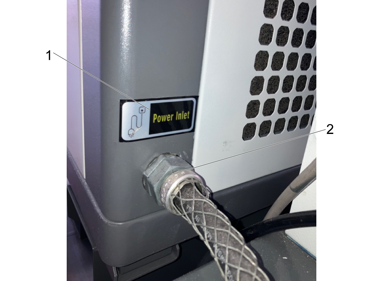
Feed the power supply pigtail extension cable to the electrical cabinet through the enclosure panel located on the left side of the main compressor unit behind the compressed air dryer. 

Note: The power cable port is shown in the image. There is a decal labeled "Power Inlet" [1] to help locate where to feed the cable through the enclosure [2].

3

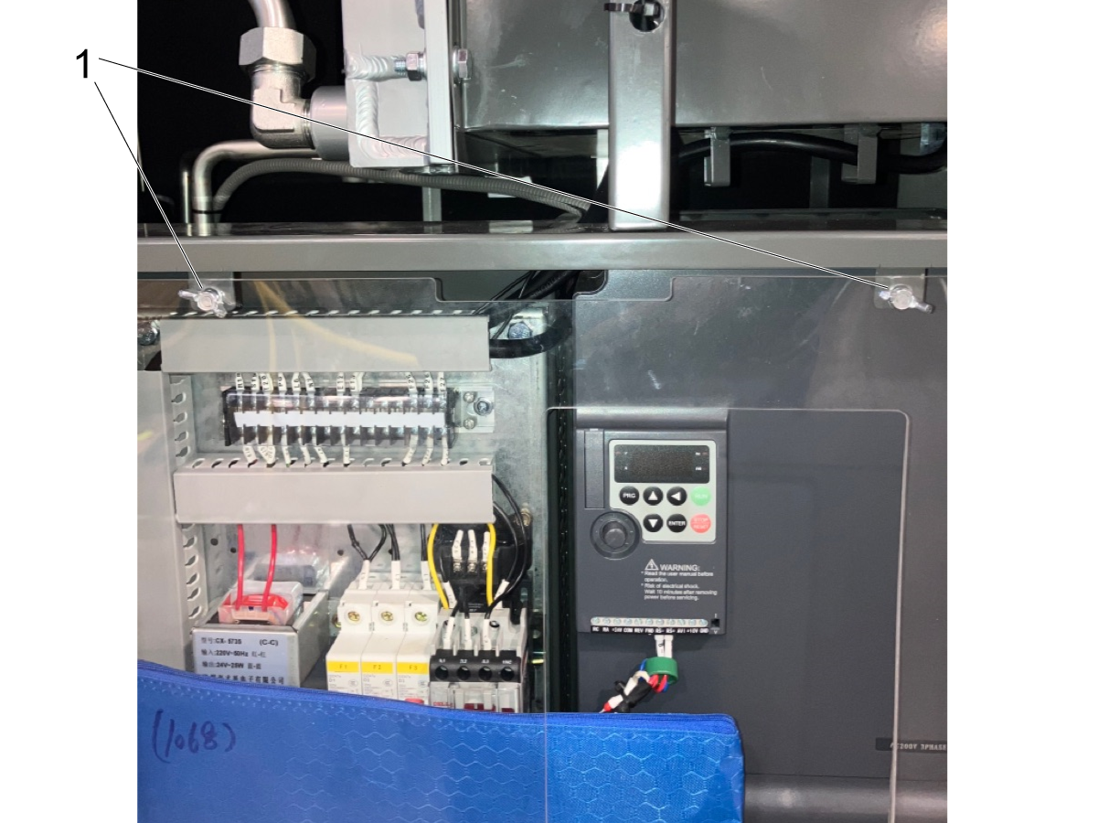
Remove the rear enclosure panel to gain access to the electrical cabinet. The electrical cabinet has a pane of safety glass that needs to be removed in order to access the electrical terminals.

Unfasten the wingnuts [1] securing the safety glass in position.

Remove the glass and feed the power supply extension cable through the side port.

4

WARNING: Do not make electrical connections with the extension cable plugged into the power supply source. Make sure the line is disconnected before making the connections outlined in the next step.

5

Variable Speed Wiring:

After feeding the pigtail through the power inlet port [1] connect the L1 [2], L2 [3], and L3 [4] lines of the power supply pigtail cable to the respective terminals of the electrical cabinet.

Once you have verified these lines are securely connected and the ground wire [5] is also installed, connect the pigtail cable to the power supply source cable.

Note: This image shows where to make the electrical connections on a variable speed air compressor. See the next step for the electrical connections on a single speed compressor.

6

Single Speed Wiring:

Feed the power pigtail through the power inlet port. Then make the connections to the power pigtail.

Note: The wiring is the same as it is for the variable speed compressor in the previous step. The location of the electrical terminals is different between the compressors.

Connect L1 [1] L2 [2] L3 [3] and the ground [4] from the incoming power supply pigtail to the terminal.

Once connections on the terminal are made and verified, connect the pigtail to the power supply.

2.2 HAC30-VS Installation

Introduction

This chapter of the manual provides details about how to install the Haas Air Compressor - 30HP. This chapter gives information about pre-installation precautions, installation requirements, and electrical installation requirements for both the fixed speed and variable speed versions.

Air Compressor Pre-Installation

1

When storing the air compressor pre-installation, the compressor should be placed in a dry area that has a typical ambient temperature between 41-112 degrees Fahrenheit

2

The single speed and variable speed air compressors have the same physical footprint and weight. Refer to section 1.2 to see the specifications of the compressors. The compressors weigh approximately 1015 lbs. 

3

Move the air compressor as close to it's installation location as possible before removing the compressor from the protective packaging. To make it easier to move the compressor, leave it secured to the pallet.

When ready to install the compressor, unfasten the feet from the pallet. Each foot connected to the storage tank has a bolt [1] fastened to the pallet as shown in the image.

HAC30-VS - Installation

1

Once the feet have been unfastened from the pallet, use the forklift to move the compressor to it's installation location. The installation location should adhere to the following specifications:

  • The ambient temperature where the air compressor will operate should be between 41-112 Fahrenheit (5-45 Celsius).
  • The compressor should be operated in a brightly lit area for the operators safety.
  • The air compressor should not be installed in an area that has a high risk of fire.
  • The compressor must be installed in a well ventilated area that has a large supply of dust-free air. If the air quality is low, the air filter may need to be cleaned or replaced more frequently than what is listed in the maintenance chapter of this manual.

Important: It is recommended to use the compressor indoors. If there is outdoor space that is well protected from rain or extreme elements, the air compressor can be installed in an outdoor location.

Warning: Exposure to the elements can cause damage to components or an increased frequency of maintenance required.

 Note: The performance of the compressor may decrease in conditions with high ambient temperature and humidity above 80% or at an elevation higher than 3,200 feet.

2

The image shows the recommended ventilation and minimum spacing requirements needed for a compressor to run efficiently.

  • At least 3 ft (1 meter) [1] spacing between compressors and between the sides of the compressors and any walls as shown in the image.
  • The compressor needs to be in an area with a ceiling clearance of at least 8.2 ft (2.5 meters) [2].
  • At least 3 ft (1 meter) [3] of spacing from any walls in the front or back of the compressor so that it can be easily serviced.

3

When determining the location of the compressor, there needs to be at least 3 ft (1m) of open space on the right side [1] of the compressor.

Note: This is so that the oil discharge port [2] and oil intake [3] can be easily accessed when performing oil changes.

 Important: The air compressor will come with oil inside the oil reservoir. The oil that is supplied with the air compressor is for the first maintenance oil change. The compressor does not need to be filled with oil at install.

4

Route the black airlines [1] connected to the oil-water separators [2] to a discharge container [6].

Leave the ball valve at the bottom of the tank open always. This only needs to be closed when performing maintenance on the mesh filter right after the ball valve.

Important: The red ball valves [3] located on the oil-water separators need to be manually opened weekly to drain the water. The drain valves need to be fully closed when the air compressor is being used.

Route the airlines coming from the separators to the manifold [4] that is connected to the timer valve [5]. Route the output line [7] of the manifold to a discharge container [6]. See section 3.1 Operation for details on configuring the timer drain.

5

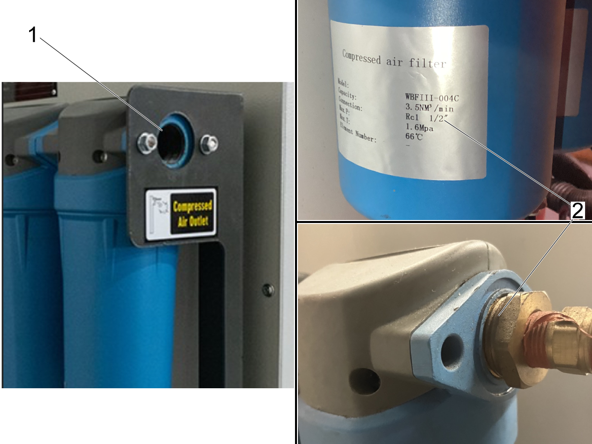
Connect an airline to the outlet of the compressed air filter [1] shown in the image.

Note: The thread for the male fitting needed to connect the airline to the filter is defined on the label on the filter cannister [2].

The thread type for HAC30-VS compressor is an going to be a  RC-1-1/2" thread [2]. Verify on the filter cannister at installation.

Electrical Installation

1

Warning: The compressor must have a ground connection when connecting it to the power supply. Connecting the compressor to the power supply is dangerous and should be done by qualified personnel only.

To connect the air compressor to power, make sure that the appropriate power supply is being used.

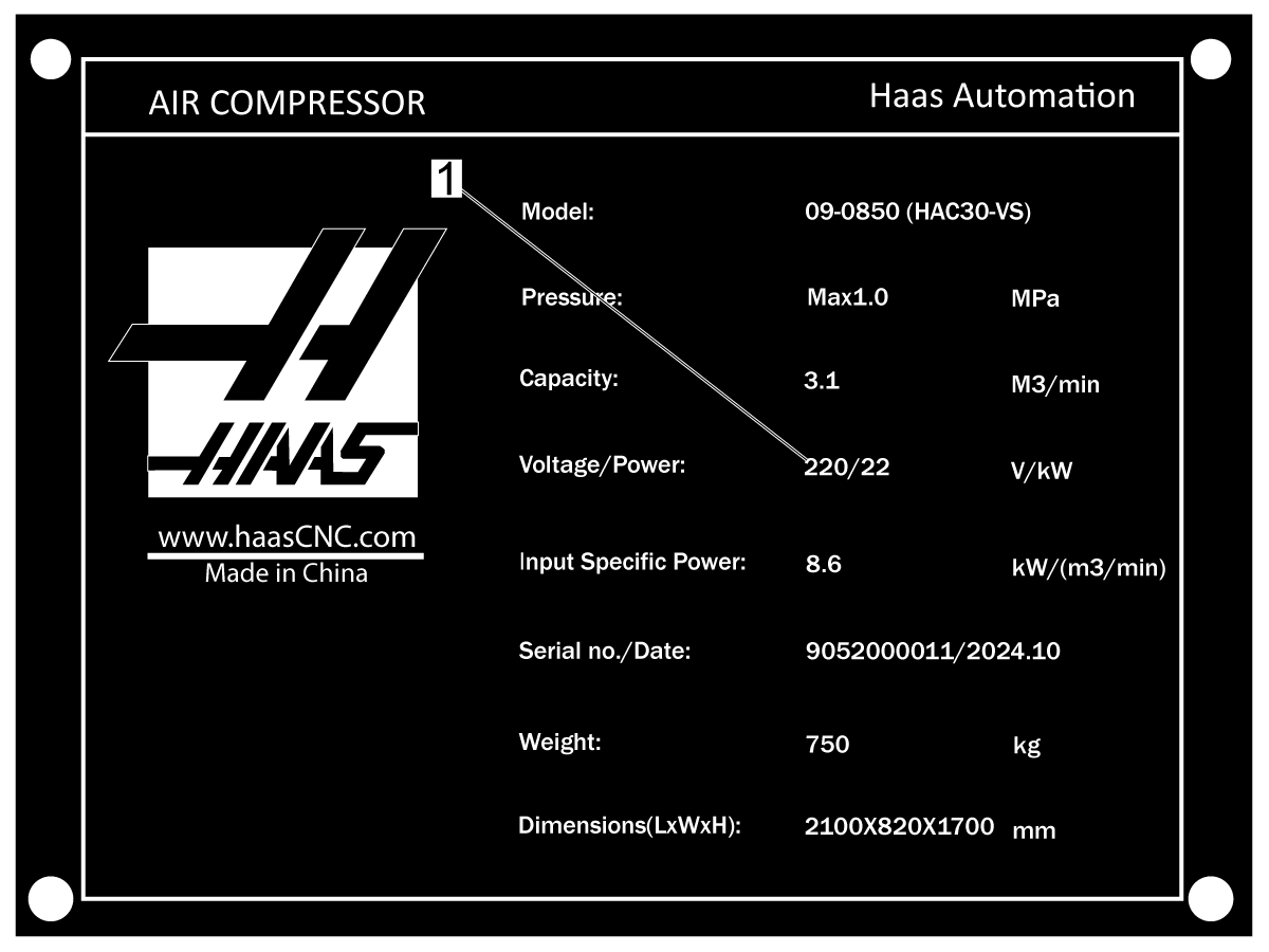
Verify that the incoming voltage meets the electrical specifications for the air compressor listed on the specification plate. Compressors can be 220VAC / 3Phase or 380VAC / 3Phase.

Note: The specification plate shown in the image is for  220 VAC [1] since it is the United States version. Compressors in Europe are made for 380 VAC. Check the specification plate to confirm before you connect the incoming power.

2

Feed the power supply pigtail extension cable to the electrical cabinet through the enclosure panel located on the left side of the main compressor unit behind the compressed air dryer. 

Note: The power cable port is shown in the image. There is a decal labeled "Power Inlet" [1] to help locate where to feed the cable through the enclosure [2].

3

Remove the rear enclosure panel to gain access to the electrical cabinet. The electrical cabinet has a pane of safety glass that needs to be removed in order to access the electrical terminals.

Unfasten the wingnuts [1] securing the safety glass in position.

Remove the glass and feed the power supply extension cable through the side port.

4

WARNING: Do not make electrical connections with the extension cable plugged into the power supply source. Make sure the line is disconnected before making the connections outlined in the next step.

5

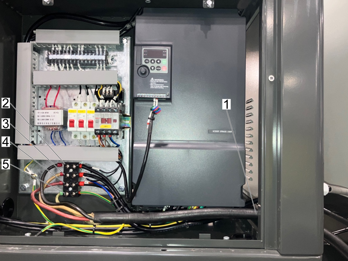
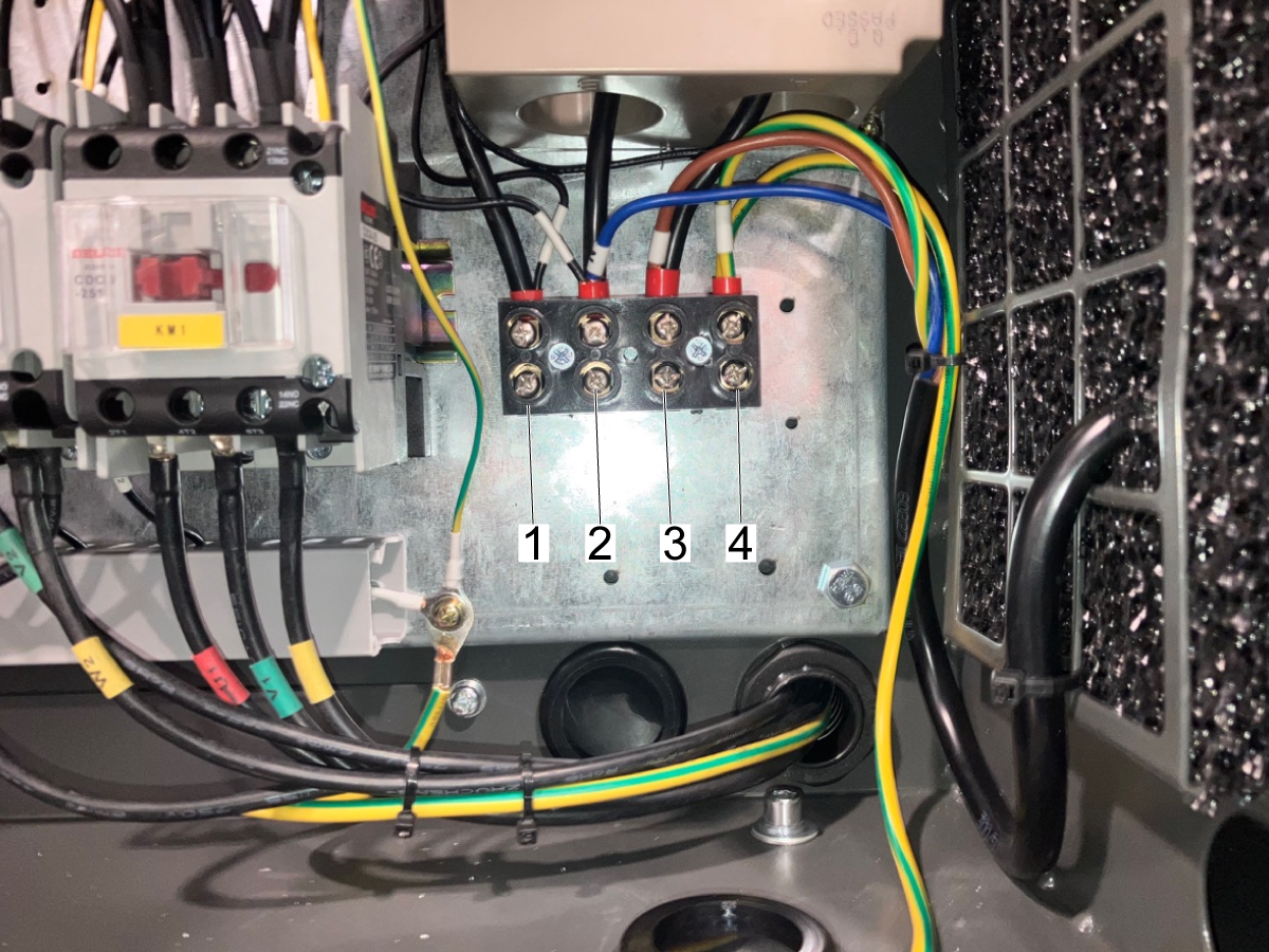
After feeding the pigtail through the power inlet port connect the L1 [1], L2 [2], and L3 [3] lines of the power supply pigtail cable to the respective terminals of the electrical cabinet.

Once you have verified these lines are securely connected and the ground wire [4] is also installed, connect the pigtail cable to the power supply source cable.

Note: This image shows where to make the electrical connections on a variable speed air compressor. See the next step for the electrical connections on a single speed compressor.

6

Once all connections are secure connect the power cable to the supply voltage.

The control will power ON automatically when the compressor is connected to power.

Check to see if you receive a Phase Wrong Alarm at the bottom of the screen. If you do get this alarm, disconnect the power cable and swap the wires at the L1 and L3 terminals.

Once the phase alarm is cleared you are done with the electrical installation of the machine.

Recently Viewed Items

You Have No Recently Viewed Items Yet

Feedback
Haas Logo

Haas Delivered Price

This price includes shipping cost, export and import duties, insurance, and any other expenses incurred during shipping to a location in France agreed with you as a buyer. No other mandatory costs can be added to the delivery of a Haas CNC Product.

KEEP UP WITH THE LATEST HAAS TIPS AND TECHNOLOGY...

Sign up now!   

HAAS TOOLING ACCEPTS THE FOLLOWING:

  • Service & Support
  • Owners
  • Request Service
  • Operator Manuals
  • Haas Parts
  • Rotary Repair Request
  • Pre-Install Guides
  • Shopping Tools
  • Build & Price a New Haas
  • Available Inventory
  • The Haas Price List
  • CNCA Financing
  • About Haas
  • Accessibility Statement
  • DNSH Statement
  • Export Compliance
  • Careers
  • Certifications & Safety
  • Contact Us
  • History
  • Terms & Conditions
  • Haas Tooling Terms & Conditions
  • Privacy
  • Warranty
  • Haas Community
  • Haas Certification Program
  • Haas Motorsports
  • Gene Haas Foundation
  • Haas Technical Education Community
  • Events

  • Join the Conversation
  • Facebook
  • X
  • Flickr
  • YouTube
  • LinkedIn
  • Instagram
  • TikTok
© 2026 Haas Automation, Inc – CNC Machine Tools

This site is protected by reCAPTCHA and the Google Privacy Policy and Terms of Service apply.

2800 Sturgis Rd., Oxnard, CA 93030
Toll Free: (888) 817-4446 / Fax: 805-278-8554