My Haas Welcome,
!
Haas Tooling MyHaas/HaasConnect Sign In Register Haas Tooling MyHaas/HaasConnect Sign Out Welcome, My Machines Latest Activity My Quotes My Account My Users Sign Out
Find Your Distributor
  1. Select Language
    1. English
    2. Deutsch
    3. Español - ES
    4. Español - MX
    5. Français
    6. Italiano
    7. Português
    8. Český
    9. Dansk
    10. Nederlands
    11. Magyar
    12. Polski
    13. Svenska
    14. Türkçe
    15. 中文
    16. Suomi
    17. Norsk
    18. الإنجليزية
    19. български
    20. Hrvatski
    21. Ελληνικά
    22. Română
    23. Slovenský
    24. Slovenščina
    25. 한국어
    26. 日本語
    27. Українська
  • machines Main Menu
    • Vertical Mills
      Vertical Mills
      Vertical Mills View All
      • Vertical Mills
      • VF Series
      • Universal Machines
      • VR Series
      • VP-5 Prismatic
      • Pallet-Changing VMCs
      • Mini Mills
      • Mold Machines
      • High-Speed Drill Centers
      • Drill/Tap/ Mill Series
      • Toolroom Mills
      • Pocket Mill
      • Compact Mills
      • Gantry Series
      • SR Sheet Routers
      • Extra-Large VMC
      • Double-Column Mills
      • 3+2 Positioning Machines
    • Multi-Axis Solutions
      Multi-Axis Solutions
      Multi-Axis Solutions View All
      • Multi-Axis Solutions
      • Y-Axis Lathes
      • 5-Axis Mills
    • Lathes
      Lathes
      Lathes View All
      • Lathes
      • ST Series
      • Dual-Spindle
      • Box Way Series
      • Toolroom Lathes
      • Chucker Lathe
      • Pocket Lathe
      • Haas Bar Feeders
    • Horizontal Mills
      Horizontal Mills
      Horizontal Mills View All
      • Horizontal Mills
      • 50-Taper
      • 40-Taper
    • Rotaries & Indexers
      Rotaries & Indexers
      Rotaries & Indexers View All
      • Rotaries & Indexers
      • Rotary Tables
      • Indexers
      • 5-Axis Rotaries
      • Extra-Large Rotaries
    • Special Series
      Special Series
      Special Series View All
      • Special Series
      • EU_Series_Redirect
    • Automation Systems
      Automation Systems
      Automation Systems View All
      • Automation Systems
      • Mill Automation
      • Lathe Automation
      • Automatic Parts Loaders
      • Automation Models
    • Desktop Machines
      Desktop Machines
      Desktop Machines View All
      • Desktop Machines
      • Desktop Mill
      • Desktop Lathe
      • Control Simulator, Standard
      • Control Simulator, Premium
    • Shop Equipment
      Shop Equipment
      Shop Equipment View All
      • Shop Equipment
      • Knee Mill
      • Haas Manual Lathes
      • Haas Saws
    • Fabrication Machines
      Fabrication Machines
      Fabrication Machines View All
      • Fabrication Machines
      • Laser Cutting Machines
      • CNC Press Brakes
    • QUICK LINKS Special Series  Special Series 
      EU SERIES EU SERIES BUILD & PRICE | PRICE LIST BUILD & PRICE | PRICE LIST In-Stock Machines In-Stock Machines WHAT’S NEW WHAT’S NEW YOUR FIRST CNC YOUR FIRST CNC
      SHOPPING TOOLS
      • Build & Price a Haas
      • Price List
      • Available Inventory
      • CNCA Financing
      WANT TO TALK TO SOMEONE?

      A Haas Factory Outlet (HFO) can answer your questions, and walk you through your best options.

      CONTACT YOUR DISTRIBUTOR >
  • Options Main Menu
    • The Haas Control Value Option Packages
      Value Option Packages
      Value Option Packages View All
      • Value Option Packages
    • Product Image Spindles
      Spindles
      Spindles View All
      • Spindles
    • Product Image Tool Changers
      Tool Changers
      Tool Changers View All
      • Tool Changers
    • Product Image 4th- | 5th-Axis
      4th- | 5th-Axis
      4th- | 5th-Axis View All
      • 4th- | 5th-Axis
    • Product Image Turrets & Live Tooling
      Turrets & Live Tooling
      Turrets & Live Tooling View All
      • Turrets & Live Tooling
    • Product Image Probing
      Probing
      Probing View All
      • Probing
    • Haas Chip & Coolant Management Chip & Coolant Management
      Chip & Coolant Management
      Chip & Coolant Management View All
      • Chip & Coolant Management
    • The Haas Control The Haas Control
      The Haas Control
      The Haas Control View All
      • The Haas Control
    • Product Image Product Options
      Product Options
      Product Options View All
      • Product Options
    • Product Image Tooling & Fixturing
      Tooling & Fixturing
      Tooling & Fixturing View All
      • Tooling & Fixturing
    • Product Image Workholding
      Workholding
      Workholding View All
      • Workholding
    • Product Image 5-Axis Solutions
      5-Axis Solutions
      5-Axis Solutions View All
      • 5-Axis Solutions
      • 5 Easy Steps to 5-Axis
    • QUICK LINKS Special Series  Special Series 
      EU SERIES EU SERIES BUILD & PRICE | PRICE LIST BUILD & PRICE | PRICE LIST In-Stock Machines In-Stock Machines WHAT’S NEW WHAT’S NEW YOUR FIRST CNC YOUR FIRST CNC
      SHOPPING TOOLS
      • Build & Price a Haas
      • Price List
      • Available Inventory
      • CNCA Financing
      WANT TO TALK TO SOMEONE?

      A Haas Factory Outlet (HFO) can answer your questions, and walk you through your best options.

      CONTACT YOUR DISTRIBUTOR >
  • Why Haas Main Menu
      Discover the Haas Difference
    • Why Haas
    • MyHaas
    • Education Community
    • Industry 4.0
    • Haas Certification
    • Customer Testimonials
  • Service Main Menu
      Welcome to Haas Service
      SERVICE HOME Operator’s Manuals How-To Procedures Troubleshooting Guides Preventive Maintenance Haas Parts Haas Tooling Videos
  • Videos Main Menu
  • Main Menu
    • View All
    • View All
    • View All
    • View All
      • HTEC Curriculum Support
      • Haas Value Option Packages (VOP) Journey
    • View All
      • Haas 10 kg Cobot Package
      • Cobot Kits
      • DC-1 Drill Center
      • CNC Sales News
      • Do More With Your Haas
    • View All
    • View All
      • contact-us-test
      • 4 - AUTOMATION SYSTEMS
      • Carousel-V2
      • expert test
      • Demo_Day_Trident-test
      • Link Test
      • image-sale-tag-test
      • article-list-test
      • Haas 25 kg Robot Package
      • test-algolia-page
    • View All
    • View All
    • View All
    • View All
      • calc-test
    • View All
    • QUICK LINKS Special Series  Special Series 
      EU SERIES EU SERIES BUILD & PRICE | PRICE LIST BUILD & PRICE | PRICE LIST In-Stock Machines In-Stock Machines WHAT’S NEW WHAT’S NEW YOUR FIRST CNC YOUR FIRST CNC
      SHOPPING TOOLS
      • Build & Price a Haas
      • Price List
      • Available Inventory
      • CNCA Financing
      WANT TO TALK TO SOMEONE?

      A Haas Factory Outlet (HFO) can answer your questions, and walk you through your best options.

      CONTACT YOUR DISTRIBUTOR >
  • Haas Tooling Main Menu
  • Haas Service Parts Main Menu

My Haas Welcome,
!
Haas Tooling MyHaas/HaasConnect Sign In Register Haas Tooling MyHaas/HaasConnect Sign Out Welcome, My Machines Latest Activity My Quotes My Account My Users Sign Out
Find Your Distributor
  1. Select Language
    1. English
    2. Deutsch
    3. Español - ES
    4. Español - MX
    5. Français
    6. Italiano
    7. Português
    8. Český
    9. Dansk
    10. Nederlands
    11. Magyar
    12. Polski
    13. Svenska
    14. Türkçe
    15. 中文
    16. Suomi
    17. Norsk
    18. الإنجليزية
    19. български
    20. Hrvatski
    21. Ελληνικά
    22. Română
    23. Slovenský
    24. Slovenščina
    25. 한국어
    26. 日本語
    27. Українська
×

Search Results

Web Pages

Images

    • <
    • 1
    • >

4 - Haas Air Compressor - Maintenance

Haas Air Compressor - Operators/Service Manual


  • 0 - Haas Air Compressor - Table of Contents
  • 1 - Haas Air Compressor - Introduction
  • 2 - Haas Air Compressor - Installation
  • 3 - Haas Air Compressor - Operation
  • 4 - Haas Air Compressor - Maintenance
  • 5 - Haas Air Compressor - Troubleshooting

Go To :

  • 4.1 HAC15 Maintenance
  • 4.2 HAC30 - Maintenance
  • 4.3 HAC15 - SERVICE PARTS LIST
  • 4.4 HAC30 - SERVICE PARTS LIST

4.1 HAC15 Maintenance

Recently Updated

HAC15 - Fixed Speed and Variable Speed - Maintenance


Revision B - 09/2025

Overview

This chapter provides information on what maintenance is needed for both the single and variable speed air compressors. There is a maintenance schedule as well as instructions on how to perform the required maintenance.

Maintenance Schedule

This chart details what components need maintenance and the required intervals for performing the maintenance. In addition to following the maintenance schedule below, daily inspection of the air compressor should be performed to keep the components clean and reduce the risk of component failure.

The daily/weekly inspection should consist of:

  • Check oil level
  • Look for oil leakage
  • Check pipelines and air hoses for leaks
  • Check pressure gauge
  • Check auto drainer behavior
  • Manually drain oil-water separators
  • Monitoring the control display

Note: The maintenance schedule below applies to both the single and variable speed air compressors 

Important: To ensure compressor performance, follow all items on the maintenance schedule. Also, consult your local municipality's codes for any required annual inspections of the tank itself. 

Maintenance Schedule
Maintenance Item Interval
Air Filter Clean After 500 Hours Replace After 2000 Hours
Oil Filter* Replace After 3000 Hours
Oil-Air Separator Replace After 3000 Hours
Oil* Replace After 3000 Hours
Oil Level Check Daily
Pre-filter Clean Weekly
Radiator Clean Weekly
Electrical Components and Connector Check After 500 Hours
Oil-Water Separator Filters Check After 500 Hours Replace After 3000 Hours
Drain Oil-Water Separators Weekly
Purge Solenoid Test Weekly
Mesh Purge Line Filter Clean Every 2 Months Or As Needed

Important* For new air compressors, the oil and oil filter need to be replaced after the first 500 hours of run time. After the first replacement, these components can be replaced every 3000 hours of run time.

Maintenance

1

Oil Replacement:

To gain access to the oil intake remove the right side enclosure panel.

Power off the compressor and allow 5 minutes for the system to cool.

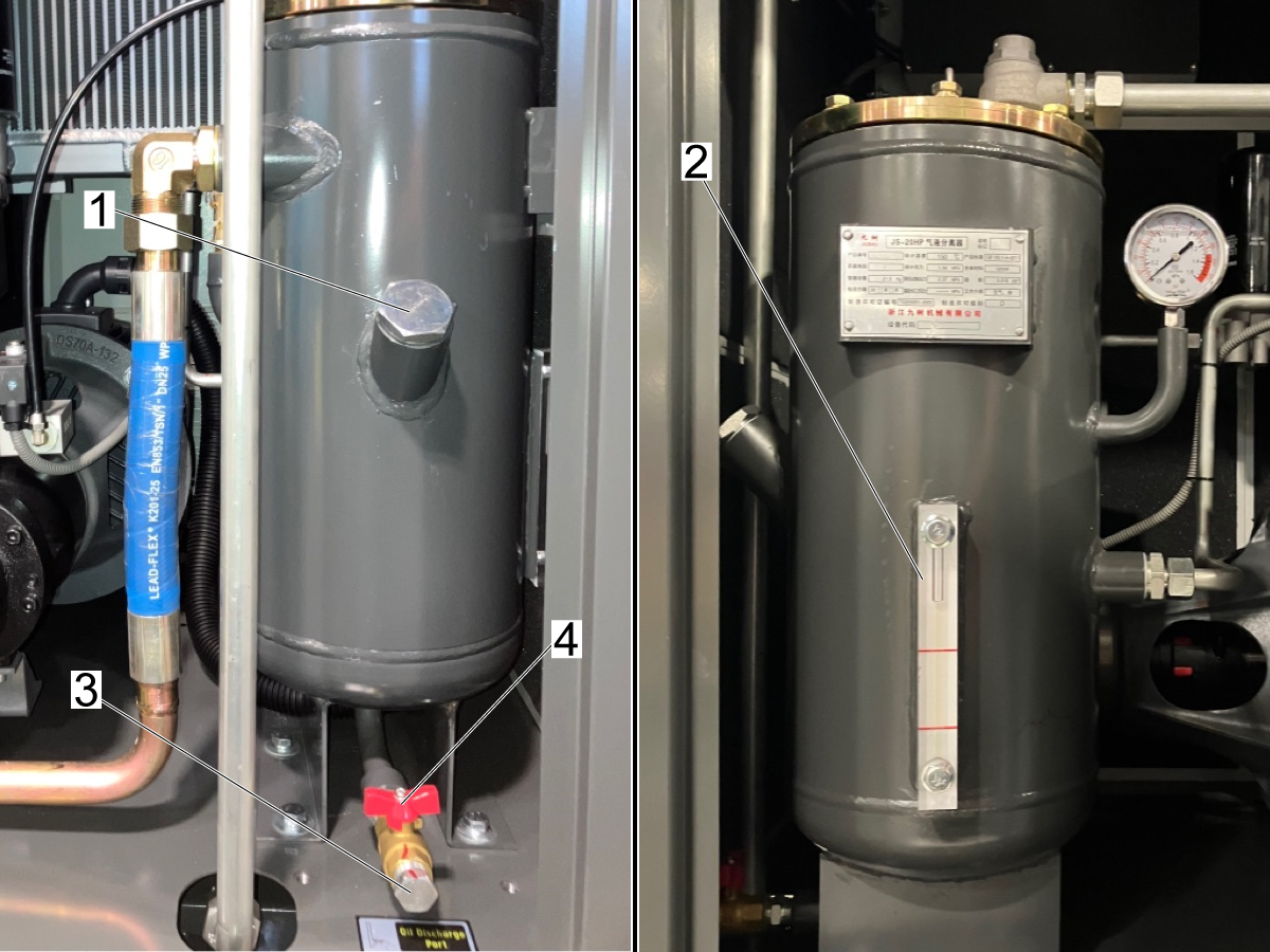
Purge the air from the system until both the gauges on the storage tank [1] and the oil-air separator unit [2] show zero pressure.

There cannot be any pressure inside the oil-air separator when the intake cap is removed. 

IMPORTANT: Before removing the cap to the oil intake, make sure that there is no residual pressure inside of the compressor. This can be verified from the pressure gauge [2] on the oil-air separator unit and the pressure gauge on the air tank [1].

After you have verified no pressure in the compressor, use a wrench to remove the oil intake cap [1] and inspect the oil level gauge [2] to check how much oil should be added.

To drain the oil, use an adjustable wrench to remove the discharge cap [3] and then open the oil discharge valve [4] to allow oil to drain the compressor.

Allow some time for the oil to fully drain from the compressor system, then close the discharge drain.

Add oil into the intake port [1] so that the level is close to the upper red line on the oil level gauge.

The HAC15 requires around 7 quarts of oil for each oil change.

Make sure to reinstall and tighten the oil intake cap after adding the oil.

Note: It is recommended to use Mobil Rarus 427 oil for the air compressor.

Important: The oil needs to be changed after the initial 500 hours of run time and then every 2500-3000 hours of use.

If the compressor is only being run for a few hours a day, it's recommended to change the oil every 6 months.

Important: Different brands of oil cannot be mixed. Make sure the oil being used is suitable with the ambient temperature of the air compressor.


2

Oil Filter (09-0965):

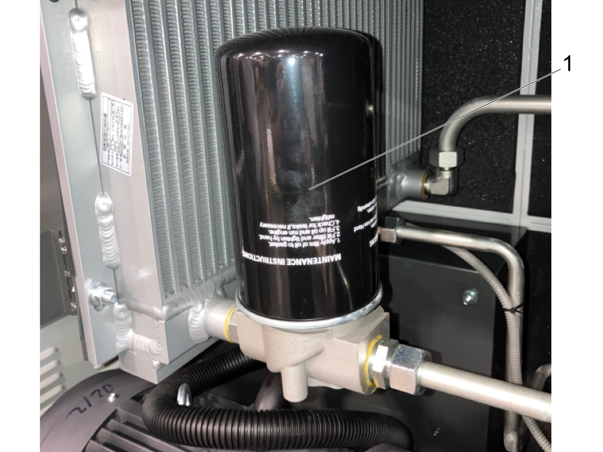
The oil filter is located above the compressor motor, in front of the left side of the cooling unit.

To access the oil filter, remove the front enclosure panel. The filter cartridge is shown in the image [1].

To replace the oil filter, unfasten the filter by manually turning it and order part 09-0965.

Note: A strap wrench may be needed to remove the filter cartridge

Prior to installing the new filter cartridge, make sure to lubricate the sealing gasket to ensure a complete seal and prevent any leaks.

3

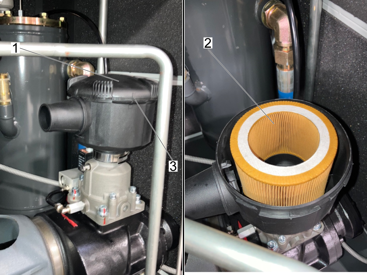
Air Filter (09-0967):

To replace the air intake filter, remove the front enclosure panel and remove the cover of the air intake.

The air intake is located directly above the compressor screw assembly.

Remove the cover [1] by rotating the cover.

Remove the filter element [2] to replace it with the new filter. 

Reinstall the air intake cover and verify it is tightened by aligning the arrows [3].

Note: Replace the filter element in accordance of the Maintenance Schedule above. Replacement filters can be ordered as part number 09-0967.

4

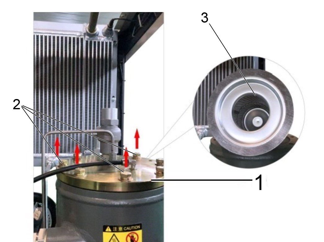
Oil-Air Separator Filter (93-4388):

Shut down the air compressor and allow at minimum 5 minutes before performing any maintenance. The compressor needs to be de-pressurized before removing any fittings.

To gain access to the oil-air separator, remove the right and rear enclosure panels from the compressor.

Disconnect all pipes and valves connected to the cover plate[1] of the oil-air separator. Unfasten the 8 bolts [2] from the cover plate, and remove the plate to access the filter element [3].

Note: Before replacing the filter element make sure to lubricate the sealing gasket.

5

Oil-Water Separator Filters (09-0791):

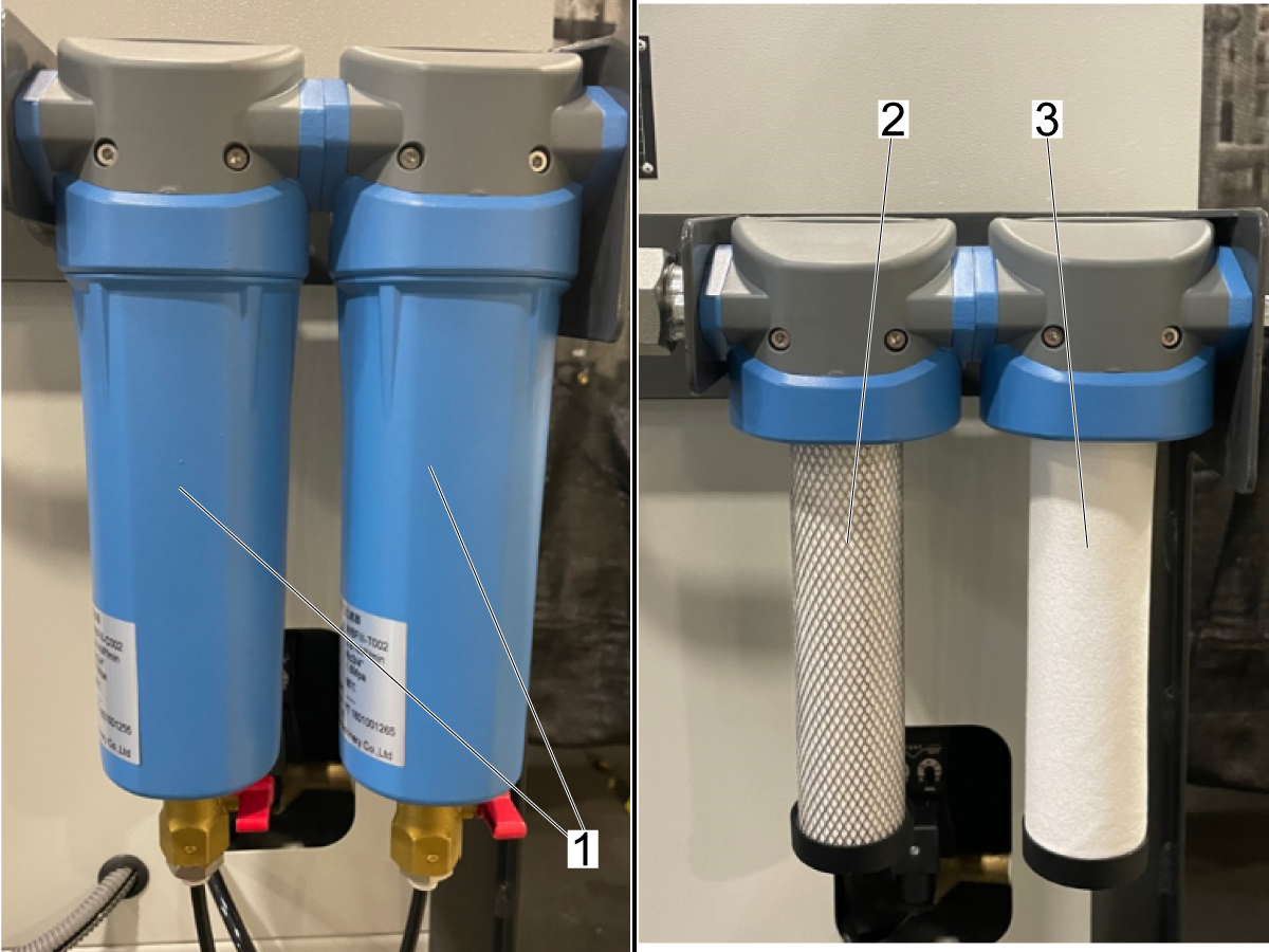
The oil-water separators are located on the back of the air dryer unit. 

To replace these filters, unfasten the bottom cannisters [1] by rotating them counter clockwise. Once removed you will see the filter elements.

Note: The filter elements are not identical. Make sure the correct filter is installed on the correct component as shown in the image. Filter [2] is for the left separator component and the filter [3] is for the right separator component.

Unfasten the filter element. When installing the replacement filter, make sure that the filter is fully tightened and that the gasket is in place.

6

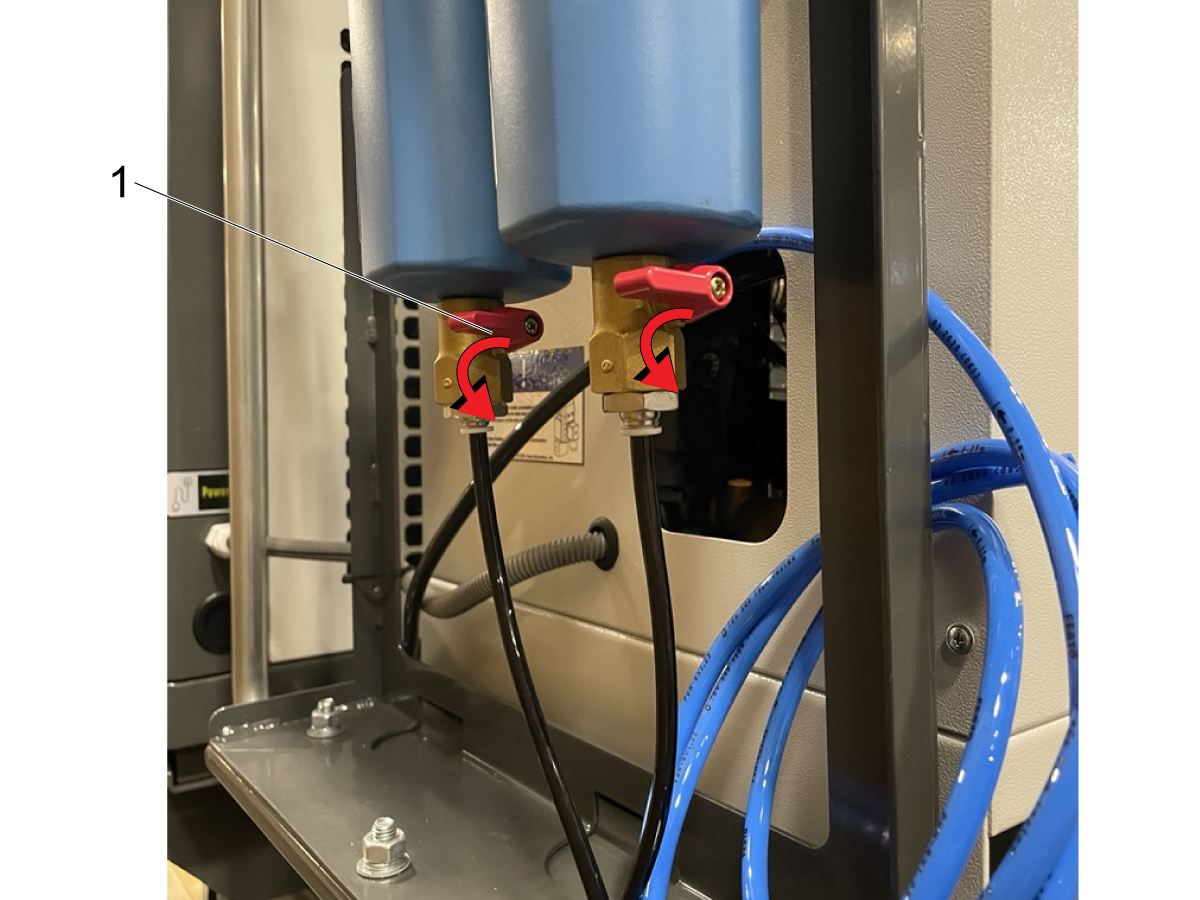
Drain Oil-Water Separators:

Use the red ball valves [1] to purge the water in the oil-water separators into the discharge container.

Note: These ball valves should be opened weekly depending on compressor usage.

Important: After opening the valves until the water is drained, make sure to fully close the ball valves before using the compressor again.

7

Radiator:

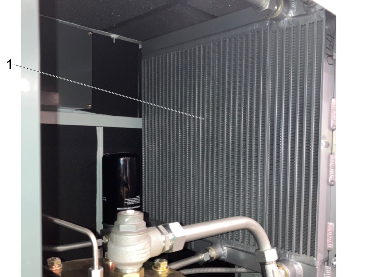
Inspect the radiator vents for cleanliness every week.

To access the radiator, remove the front and rear enclosure panels.

The radiator is located above the compressor motor as shown in the image [1].

The radiator vents can be cleaned with either compressed air or a soft fiber brush. Not cleaning the radiator can decrease the cooling efficiency of the system.

Note: Do not use water or a steel brush to clean the vents. The electrical cabinet is located beneath the radiator that can be damaged by water or other liquids.

8

Clean Mesh Purge line Filter:

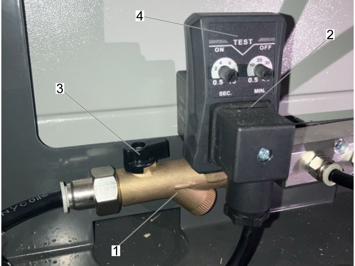
The purge line for the air tank and the dryer are teed together and connect to the purge manifold shown in the image.  There is a mesh filter inside the brass y-strainer [1] located before the timer solenoid [2].

Close the black valve [3] at the start of the y-strainer.

Press the test button [4] on the timer solenoid so that the compressed air is purged from the y-strainer and the drain line.

9

Once the cap [1] is unfastened, remove the mesh strainer element [2] so that it can be cleaned. 

Rinse the strainer in water and then blow it with compressed air until it is sufficiently clean.

Reinstall the strainer and cap into the brass housing [3]. Tighten the cap and then open the valve [4] so that the purge system can begin draining water again.

Note: Make sure that the O-ring [5] is installed and that nothing leaks from the cap once tightened.

4.2 HAC30 - Maintenance

Recently Updated

HAC30-VS - Maintenance


Revision A - 11/2025

Overview

This chapter provides information on what maintenance is needed for a HAC30-VS unit. There is a maintenance schedule as well as instructions on how to perform the required maintenance below.

Maintenance Schedule

This chart details what components need maintenance and the required intervals for performing the maintenance. In addition to following the maintenance schedule below, daily inspection of the air compressor should be performed to keep the components clean and reduce the risk of component failure.

The daily/weekly inspection should consist of:

  • Check oil level
  • Look for oil leakage
  • Check pipelines and air hoses for leaks
  • Check pressure gauge
  • Check auto drainer behavior
  • Manually drain oil-water separators
  • Monitoring the control display

Note: The maintenance schedule below applies to both the single and variable speed air compressors 

Important: To ensure compressor performance, follow all items on the maintenance schedule. Also, consult your local municipality's codes for any required annual inspections of the tank itself. 

Maintenance Schedule
Maintenance Item Interval
Air Filter Clean After 500 Hours Replace After 2000 Hours
Oil Filter* Replace After 3000 Hours
Oil-Air Separator Replace After 3000 Hours
Oil* Replace After 3000 Hours
Oil Level Check Daily
Pre-filter Clean Weekly
Radiator Clean Weekly
Electrical Components and Connector Check After 500 Hours
Oil-Water Separator Filters Check After 500 Hours Replace After 3000 Hours
Drain Oil-Water Separators Weekly
Purge Solenoid Test Weekly
Mesh Purge Line Filter Clean Every 2 Months Or As Needed

Important* For new air compressors, the oil and oil filter need to be replaced after the first 500 hours of run time. After the first replacement, these components can be replaced every 3000 hours of run time.

Maintenance

1

Oil Replacement:

To gain access to the oil intake remove the right side enclosure panel.

Power off the compressor and allow 5 minutes for the system to cool.

Purge the air from the system until both the gauges on the storage tank [1] and the oil-air separator unit [2] show zero pressure.

There cannot be any pressure inside the oil-air separator when the intake cap is removed. 

IMPORTANT: Before removing the cap to the oil intake, make sure that there is no residual pressure inside of the compressor. This can be verified from the pressure gauge [2] on the oil-air separator unit and the pressure gauge on the air tank [1].

After you have verified no pressure in the compressor, use a wrench to remove the oil intake cap [1] and inspect the oil level gauge [2] to check how much oil should be added.

To drain the oil, use an adjustable wrench to remove the discharge cap [3] and then open the oil discharge valve [4] to allow oil to drain the compressor.

Allow some time for the oil to fully drain from the compressor system, then close the discharge drain.

Add oil into the intake port [1] so that the level is close to the upper red line on the oil level gauge.

Make sure to reinstall and tighten the oil intake cap after adding the oil.

Note: It is recommended to use 09-0966 which is an ISO VG 100 viscosity oil.  

Important: The oil needs to be changed after the initial 500 hours of run time and then every 2500-3000 hours of use.

If the compressor is only being run for a few hours a day, it's recommended to change the oil every 6 months.

Important: Different weight oils cannot be mixed. Make sure the oil being used is suitable with the ambient temperature of the air compressor.

2

Oil Filter (09-1137):

The oil filter is located above the compressor motor, in front of the left side of the cooling unit.

To access the oil filter, remove the front enclosure panel. The filter cartridge is shown in the image [1].

To replace the oil filter, unfasten the filter by manually turning it and order part 09-1137.

Note: A strap wrench may be needed to remove the oil filter cartridge.

Prior to installing the new filter cartridge, make sure to lubricate the sealing gasket to ensure a complete seal and prevent any leaks.

3

Air Filter (09-1136):

To replace the air intake filter, remove the front enclosure panel and remove the cover of the air intake.

The air intake is located directly above the compressor screw assembly.

Remove the cover [1] by releasing the latches [2] holding the 2 piece housing together.

Remove the filter element [3] to replace it with the new filter. 

Reinstall the air intake cover [4] and verify that the latches are tightly secured.

Note: Replace the filter element in accordance of the Maintenance Schedule above. Replacement filters can be ordered as part number 09-1136.

4

Oil-Air Separator Filter (09-1135):

Shut down the air compressor and allow at minimum 5 minutes before performing any maintenance. The compressor needs to be de-pressurized before removing any fittings.

To gain access to the oil-air separator, remove the right and rear enclosure panels from the compressor.

Disconnect all pipes and valves connected to the cover plate[1] of the oil-air separator. Unfasten the 8 bolts [2] from the cover plate, and remove the plate to access the filter element [3].

Note: Before replacing the filter element make sure to lubricate the sealing gasket.

5

Oil-Water Separator Filters (09-0791):

The oil-water separators are located on the back of the air dryer unit. 

To replace these filters, unfasten the bottom cannisters [1] by rotating them counter clockwise. Once removed you will see the filter elements.

Note: The filter elements are not identical. Make sure the correct filter is installed on the correct component as shown in the image. Filter [2] is for the left separator component and the filter [3] is for the right separator component.

Unfasten the filter element. When installing the replacement filter, make sure that the filter is fully tightened and that the gasket is in place.

6

Drain Oil-Water Separators:

Use the red ball valves [1] to purge the water in the oil-water separators into the discharge container.

Note: These ball valves should be opened weekly depending on compressor usage.

Important: After opening the valves until the water is drained, make sure to fully close the ball valves before using the compressor again.

7

Radiator:

Inspect the radiator vents for cleanliness every week.

To access the radiator, remove the front and rear enclosure panels.

The radiator is located above the compressor motor as shown in the image [1].

The radiator vents can be cleaned with either compressed air or a soft fiber brush. Not cleaning the radiator can decrease the cooling efficiency of the system.

Note: Do not use water or a steel brush to clean the vents. The electrical cabinet is located beneath the radiator that can be damaged by water or other liquids.

8

Clean Mesh Purge line Filter:

The purge line for the air tank and the dryer are teed together and connect to the purge manifold shown in the image.  There is a mesh filter inside the brass y-strainer [1] located before the timer solenoid [2].

Close the black valve [3] at the start of the y-strainer.

Press the test button [4] on the timer solenoid so that the compressed air is purged from the y-strainer and the drain line.

9

Once the cap [1] is unfastened, remove the mesh strainer element [2] so that it can be cleaned. 

Rinse the strainer in water and then blow it with compressed air until it is sufficiently clean.

Reinstall the strainer and cap into the brass housing [3]. Tighten the cap and then open the valve [4] so that the purge system can begin draining water again.

Note: Make sure that the O-ring [5] is installed and that nothing leaks from the cap once tightened.

4.3 HAC15 - Service Parts List
Recently Updated

HAC15-FS & HAC15-VS - Service Parts List

Revision D - 02/2026

Machines Part Number DESCRIPTION
HAC15-VS and HAC15-VS-FS 09-0965 OIL FILTER, AIR COMP, HAC15
09-0966 OIL, AIR COMP, HAC15
09-0967 AIR FILTER, AIR COMP, HAC15
09-0791 OIL-WATER SEPARATOR FILTERS, HAC15
08-1974 OIL CHANGE KIT, AIR COMP, HAC15
93-4388 Screw Compressor Oil-Air Separator SVC
93-4892 ACCESS PANEL LATCH HAC15
93-5092 CROSS SUPPORT REAR HAC15-VS/FS
93-5093 TOP COVER HAC15-VS/FS
93-5263 HAC15-VS/FS BREAKER
93-5290 RIGHT DOOR PANEL HAC15-VS/FS
93-5291 REAR DOOR PANEL HAC15-VS/FS
93-5292 LEFT DOOR PANEL HAC15-VS/FS
93-5448 OIL INTAKE CAP WASHER HAC15-VS/FS
93-5464 HAC15-VS/FS O-RING 85MM ID X 2.62MM CS
93-5637 KEYED LATCH PANEL CE HAC15-VS/FS
93-5641 HOSE HAC15-VS/FS
93-5642 Y FITTING HAC15-VS/FS
93-5662 MOTOR FIXED SPEED HAC15
93-5663 MOTOR VARIABLE SPEED HAC15
93-5856 TIMING SOLENOID HAC15
93-5882 AIR SCREW ASSEMBLY HAC15
93-5883 VARIABLE SPEED DRIVE HAC15
93-5884 AC CONTACTOR HAC15
93-5934 MAIN CONTROLLER HAC15
93-5959 AIR PRESSURE VALVE HAC15
93-6018 AIR INTAKE VALVE HAC15
93-6026 AIR PRESSURE VALVE PLUG HAC15
93-6027 AIR PRESSURE VALVE FITG ADAPTER HAC15

4.4 HAC30 - SERVICE PARTS LIST

Recently Updated

HAC30-VS - Service Parts List

Revision B - 12/2025

Machines Part Number DESCRIPTION
HAC30-VS 09-1137 30HP OIL FILTER
09-1136 30HP AIR FILTER ELEMENT
09-1135 30HP OIL AIR SEPARATOR ELEMENT
93-5869 OIL-WATER FILTER HAC30
93-5868 MOTOR VARIABLE SPEED HAC30
93-5870 O-RING INTAKE COMPRESSOR HAC30
93-5872 DOOR PANL RIGHT HAC30
93-5871 DOOR PANL REAR HAC30
93-5873 DOOR PANL LEFT HAC30
93-5874 TOP COVER PANEL HAC30
93-5875 ELECTRICAL BREAKER HAC30
93-5885 VARIABLE SPEED DRIVE HAC30
93-5861 HOSE Y-FITTING TO TANK HAC30
93-5886 AIR INTAKE ASSY HAC30
93-5887 AIR SCREW ASSY HAC30
Feedback

Recently Viewed Items

You Have No Recently Viewed Items Yet

Feedback
Haas Logo

Haas Delivered Price

This price includes shipping cost, export and import duties, insurance, and any other expenses incurred during shipping to a location in France agreed with you as a buyer. No other mandatory costs can be added to the delivery of a Haas CNC Product.

KEEP UP WITH THE LATEST HAAS TIPS AND TECHNOLOGY...

Sign up now!   

HAAS TOOLING ACCEPTS THE FOLLOWING:

  • Service & Support
  • Owners
  • Request Service
  • Operator Manuals
  • Haas Parts
  • Rotary Repair Request
  • Pre-Install Guides
  • Shopping Tools
  • Build & Price a New Haas
  • Available Inventory
  • The Haas Price List
  • CNCA Financing
  • About Haas
  • Accessibility Statement
  • DNSH Statement
  • Export Compliance
  • Careers
  • Certifications & Safety
  • Contact Us
  • History
  • Terms & Conditions
  • Haas Tooling Terms & Conditions
  • Privacy
  • Warranty
  • Haas Community
  • Haas Certification Program
  • Haas Motorsports

  • Gene Haas Foundation
  • Haas Technical Education Community
  • Events

  • Join the Conversation
  • Facebook
  • X
  • Flickr
  • YouTube
  • LinkedIn
  • Instagram
  • TikTok
© 2026 Haas Automation, Inc – CNC Machine Tools

This site is protected by reCAPTCHA and the Google Privacy Policy and Terms of Service apply.

2800 Sturgis Rd., Oxnard, CA 93030
Toll Free: (888) 817-4446 / Fax: 805-278-8554