My Haas Welcome,
!
Haas Tooling MyHaas/HaasConnect Sign In Register Haas Tooling MyHaas/HaasConnect Sign Out Welcome, My Machines Latest Activity My Quotes My Account My Users Sign Out
Find Your Distributor
  1. Select Language
    1. English
    2. Deutsch
    3. Español - ES
    4. Español - MX
    5. Français
    6. Italiano
    7. Português
    8. Český
    9. Dansk
    10. Nederlands
    11. Magyar
    12. Polski
    13. Svenska
    14. Türkçe
    15. 中文
    16. Suomi
    17. Norsk
    18. الإنجليزية
    19. български
    20. Hrvatski
    21. Ελληνικά
    22. Română
    23. Slovenský
    24. Slovenščina
    25. 한국어
    26. 日本語
    27. Українська
  • machines Main Menu
    • Vertical Mills
      Vertical Mills
      Vertical Mills View All
      • Vertical Mills
      • VF Series
      • Universal Machines
      • VR Series
      • VP-5 Prismatic
      • Pallet-Changing VMCs
      • Mini Mills
      • Mold Machines
      • High-Speed Drill Centers
      • Drill/Tap/ Mill Series
      • Toolroom Mills
      • Pocket Mill
      • Compact Mills
      • Gantry Series
      • SR Sheet Routers
      • Extra-Large VMC
      • Double-Column Mills
      • 3+2 Positioning Machines
    • Multi-Axis Solutions
      Multi-Axis Solutions
      Multi-Axis Solutions View All
      • Multi-Axis Solutions
      • Y-Axis Lathes
      • 5-Axis Mills
    • Lathes
      Lathes
      Lathes View All
      • Lathes
      • ST Series
      • Dual-Spindle
      • Box Way Series
      • Toolroom Lathes
      • Chucker Lathe
      • Pocket Lathe
      • Haas Bar Feeders
    • Horizontal Mills
      Horizontal Mills
      Horizontal Mills View All
      • Horizontal Mills
      • 50-Taper
      • 40-Taper
    • Rotaries & Indexers
      Rotaries & Indexers
      Rotaries & Indexers View All
      • Rotaries & Indexers
      • Rotary Tables
      • Indexers
      • 5-Axis Rotaries
      • Extra-Large Rotaries
    • Special Series
      Special Series
      Special Series View All
      • Special Series
      • EU_Series_Redirect
    • Automation Systems
      Automation Systems
      Automation Systems View All
      • Automation Systems
      • Mill Automation
      • Lathe Automation
      • Automatic Parts Loaders
      • Automation Models
    • Desktop Machines
      Desktop Machines
      Desktop Machines View All
      • Desktop Machines
      • Desktop Mill
      • Desktop Lathe
      • Control Simulator, Standard
      • Control Simulator, Premium
    • Shop Equipment
      Shop Equipment
      Shop Equipment View All
      • Shop Equipment
      • Knee Mill
      • Haas Manual Lathes
      • Haas Saws
    • Fabrication Machines
      Fabrication Machines
      Fabrication Machines View All
      • Fabrication Machines
      • Laser Cutting Machines
      • CNC Press Brakes
    • QUICK LINKS Special Series  Special Series 
      EU SERIES EU SERIES BUILD & PRICE | PRICE LIST BUILD & PRICE | PRICE LIST In-Stock Machines In-Stock Machines WHAT’S NEW WHAT’S NEW YOUR FIRST CNC YOUR FIRST CNC
      SHOPPING TOOLS
      • Build & Price a Haas
      • Price List
      • Available Inventory
      • CNCA Financing
      WANT TO TALK TO SOMEONE?

      A Haas Factory Outlet (HFO) can answer your questions, and walk you through your best options.

      CONTACT YOUR DISTRIBUTOR >
  • Options Main Menu
    • The Haas Control Value Option Packages
      Value Option Packages
      Value Option Packages View All
      • Value Option Packages
    • Product Image Spindles
      Spindles
      Spindles View All
      • Spindles
    • Product Image Tool Changers
      Tool Changers
      Tool Changers View All
      • Tool Changers
    • Product Image 4th- | 5th-Axis
      4th- | 5th-Axis
      4th- | 5th-Axis View All
      • 4th- | 5th-Axis
    • Product Image Turrets & Live Tooling
      Turrets & Live Tooling
      Turrets & Live Tooling View All
      • Turrets & Live Tooling
    • Product Image Probing
      Probing
      Probing View All
      • Probing
    • Haas Chip & Coolant Management Chip & Coolant Management
      Chip & Coolant Management
      Chip & Coolant Management View All
      • Chip & Coolant Management
    • The Haas Control The Haas Control
      The Haas Control
      The Haas Control View All
      • The Haas Control
    • Product Image Product Options
      Product Options
      Product Options View All
      • Product Options
    • Product Image Tooling & Fixturing
      Tooling & Fixturing
      Tooling & Fixturing View All
      • Tooling & Fixturing
    • Product Image Workholding
      Workholding
      Workholding View All
      • Workholding
    • Product Image 5-Axis Solutions
      5-Axis Solutions
      5-Axis Solutions View All
      • 5-Axis Solutions
      • 5 Easy Steps to 5-Axis
    • QUICK LINKS Special Series  Special Series 
      EU SERIES EU SERIES BUILD & PRICE | PRICE LIST BUILD & PRICE | PRICE LIST In-Stock Machines In-Stock Machines WHAT’S NEW WHAT’S NEW YOUR FIRST CNC YOUR FIRST CNC
      SHOPPING TOOLS
      • Build & Price a Haas
      • Price List
      • Available Inventory
      • CNCA Financing
      WANT TO TALK TO SOMEONE?

      A Haas Factory Outlet (HFO) can answer your questions, and walk you through your best options.

      CONTACT YOUR DISTRIBUTOR >
  • Why Haas Main Menu
      Discover the Haas Difference
    • Why Haas
    • MyHaas
    • Education Community
    • Industry 4.0
    • Haas Certification
    • Customer Testimonials
  • Service Main Menu
      Welcome to Haas Service
      SERVICE HOME Operator’s Manuals How-To Procedures Troubleshooting Guides Preventive Maintenance Haas Parts Haas Tooling Videos
  • Videos Main Menu
  • Main Menu
    • View All
    • View All
    • View All
    • View All
      • HTEC Curriculum Support
      • Haas Value Option Packages (VOP) Journey
    • View All
      • Haas 10 kg Cobot Package
      • Cobot Kits
      • DC-1 Drill Center
      • CNC Sales News
      • Do More With Your Haas
    • View All
    • View All
      • contact-us-test
      • 4 - AUTOMATION SYSTEMS
      • Carousel-V2
      • expert test
      • Demo_Day_Trident-test
      • Link Test
      • image-sale-tag-test
      • article-list-test
      • Haas 25 kg Robot Package
      • test-algolia-page
    • View All
    • View All
    • View All
    • View All
      • calc-test
    • View All
    • QUICK LINKS Special Series  Special Series 
      EU SERIES EU SERIES BUILD & PRICE | PRICE LIST BUILD & PRICE | PRICE LIST In-Stock Machines In-Stock Machines WHAT’S NEW WHAT’S NEW YOUR FIRST CNC YOUR FIRST CNC
      SHOPPING TOOLS
      • Build & Price a Haas
      • Price List
      • Available Inventory
      • CNCA Financing
      WANT TO TALK TO SOMEONE?

      A Haas Factory Outlet (HFO) can answer your questions, and walk you through your best options.

      CONTACT YOUR DISTRIBUTOR >
  • Haas Tooling Main Menu
  • Haas Service Parts Main Menu

My Haas Welcome,
!
Haas Tooling MyHaas/HaasConnect Sign In Register Haas Tooling MyHaas/HaasConnect Sign Out Welcome, My Machines Latest Activity My Quotes My Account My Users Sign Out
Find Your Distributor
  1. Select Language
    1. English
    2. Deutsch
    3. Español - ES
    4. Español - MX
    5. Français
    6. Italiano
    7. Português
    8. Český
    9. Dansk
    10. Nederlands
    11. Magyar
    12. Polski
    13. Svenska
    14. Türkçe
    15. 中文
    16. Suomi
    17. Norsk
    18. الإنجليزية
    19. български
    20. Hrvatski
    21. Ελληνικά
    22. Română
    23. Slovenský
    24. Slovenščina
    25. 한국어
    26. 日本語
    27. Українська
×

Search Results

Web Pages

Images

    • <
    • 1
    • >

23 - VF/VM - Spindle C-Axis Drive

VF/VM-Series - Service Manual


  • 1 - VF/VM - Introduction
  • 2 - VF/VM - Specifications
  • 3 - VF/VM - Installation
  • 4 - VF/VM - Umbrella Tool Changer
  • 5 - VF/VM - HSK - SMTC
  • 6 - VF/VM - 40T/50T - SMTC
  • 7 - VF/VM - Axis Motion
  • 8 - VF/VM - HSK - Spindle
  • 9 - VF/VM - 40T - Spindle
  • 10 - VF/VM - 40T - Spindle Motor
  • 11 - VF/VM - 40T - Gearbox
  • 12 - VF/VM - 50T - Spindle
  • 13 - VF/VM - 50T - Gearbox
  • 14 - VF/VM - Lubrication Systems
  • 15 - VF/VM - Electrical Control
  • 16 - VF/VM - Chip Removal and Coolant
  • 17 - VF/VM - Workholding
  • 18 - VF/VM - Maintenance
  • 19 - VF/VM - Autodoor
  • 20 - VF/VM - Robot and Automation
  • 21 - VF/VM - Enclosure
  • 22 - VF/VM - CAN Bus Systems
  • 23 - VF/VM - Spindle C-Axis Drive

Go To :

  • 23.1 Mill - Spindle C-Axis Drive - Installation
  • 23.2 - Mill - Spindle C-Axis Drive - Troubleshooting Guide

23.1 Mill - Spindle C-Axis Drive - Installation

Recently Updated

Mill Spindle C-Axis Drive - Installation


AD0853

Revision J - 07/2026

Introduction

This procedure tells you how to install the C-Axis Angle Head Drive.

 NOTE: Follow angle tool manufacturer's guide for tooling installation and stopping block requirements.

NOTE: For custom stopping block mounting features go to Mill Spindle C-Axis Drive  and under technical documents open layout drawing.

Machine Compatibility:

  • VF-3/SS/YT
  • VF-4/SS/-V
  • VF-5/40/SS/-V
  • VF-6/40/SS, 7/40, 8/40, 9/40, 10/40, 12/40, 14/40
  • VM-3/6
  • 4th Axis Drive
     NOTE: Machines with a single-axis rotary installed require both 4th and 5th-axis drives. The C-Axis drive is not compatible with 2-axis rotaries. 
  • Software Version 100.21.000.1130 or higher
  • Sigma7 Motors

Required Tools:

  • 0.0005" Dial Indicator
  • Mag Base
  • Allen Keys
  • Box Wrench Set

This procedure applies to the following kit:

  • 93-1001223 MILL SPDL C-AXIS VMC FIELD INSTALL KIT

Installation Preparation

Follow the steps in this section if the machine was not ordered with a Mill C-Axis Drive option.

1

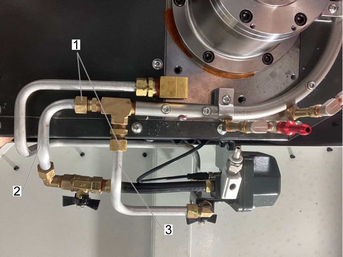
If applicable, remove the previous version of the coolant ring.

Loosen the two fittings [1] and disconnect the PCOOL Auxiliary supply line [2] and the Flood Coolant MAIN supply line [3].

2

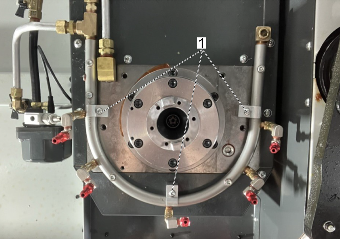
Use a 5/32" allen key to loosen the coolant ring clamps [1].

Remove the previous version of the coolant ring.

Install the updated version of the coolant ring by placing it inside the clamps and hand tighten screws to hold it in place.

Attach the coolant hoses to the new ring and tighten the fittings.

Screw in the side clamps first, then tighten the center last.

3

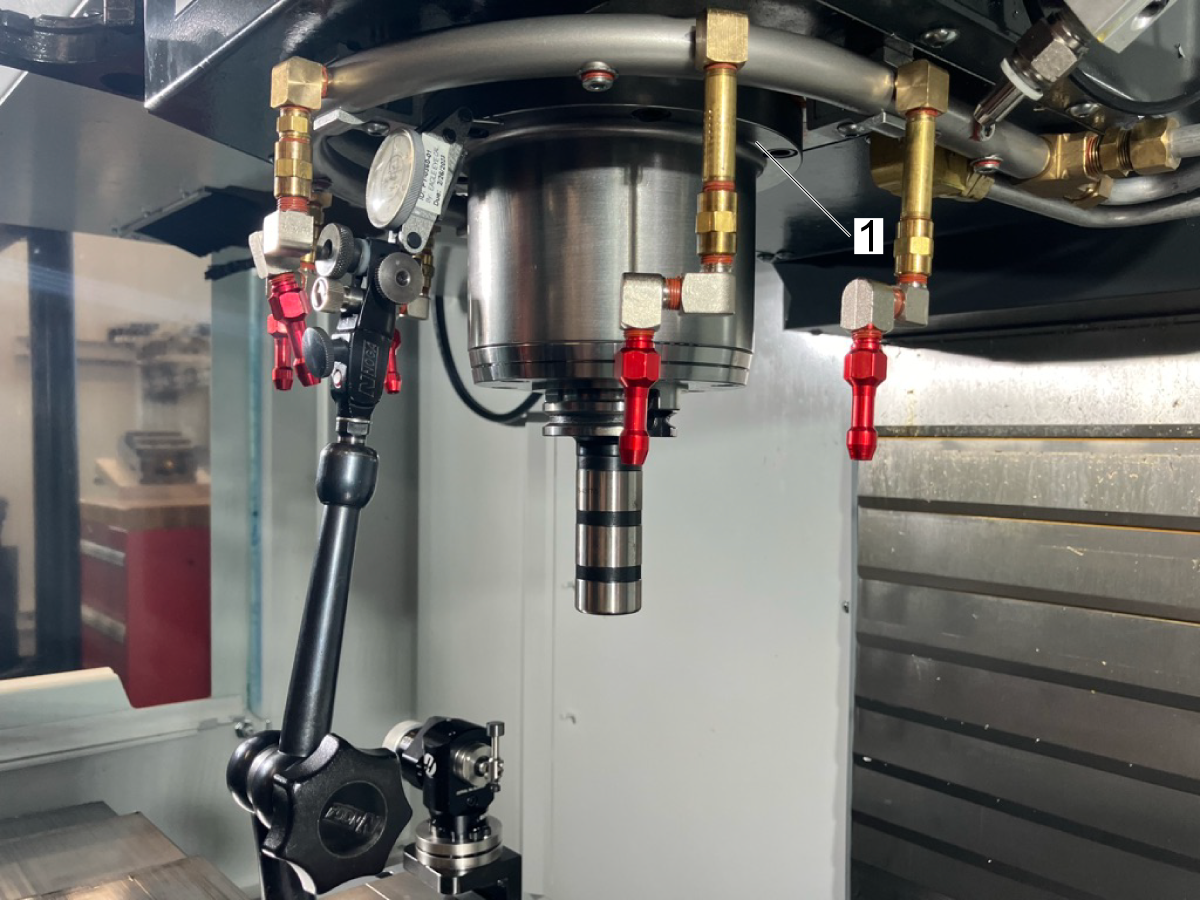
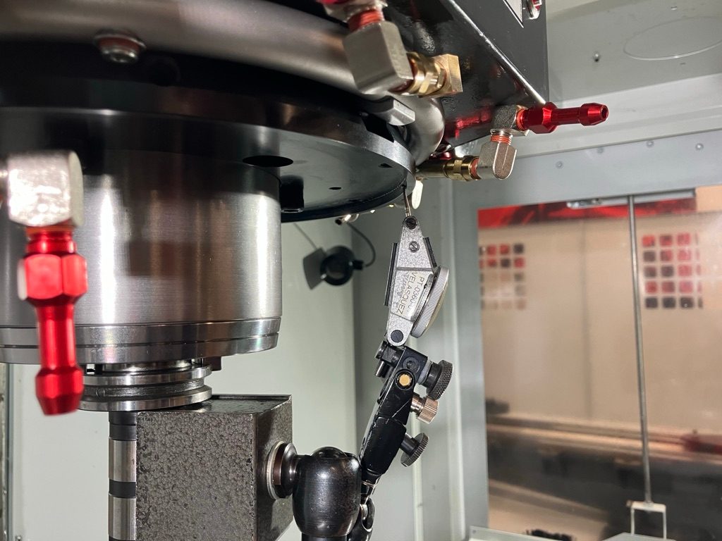
Jog the spindle down until the indicator touches the underside of the spindle nose.

Zero the indicator and the Z operator position in the control.

Jog the Z-axis away from the indicator.

Jog the machine so that the indicator touches the underside of the spindle housing flange [1].

Jog the Z-axis until the indicator is zeroed.

Record the operator Z value [A] to use in shim size calculation.


4

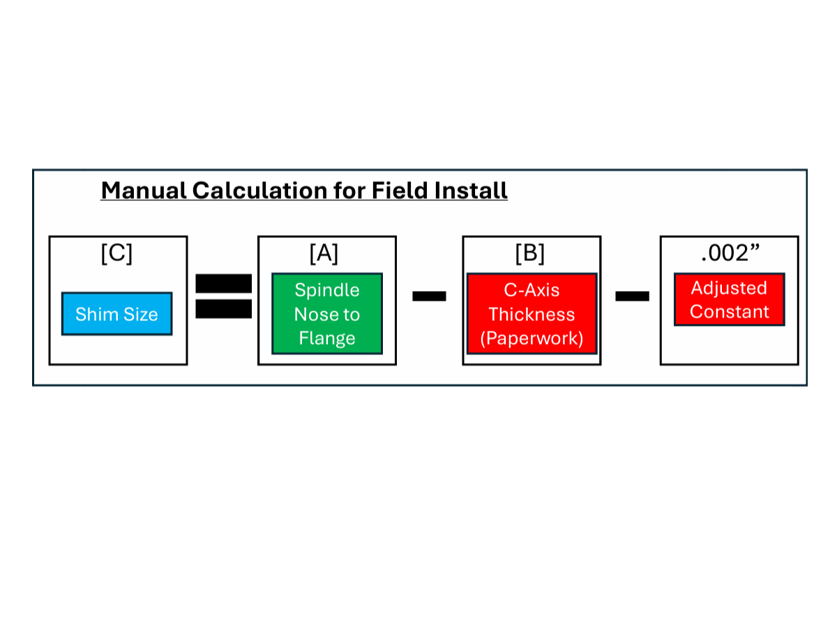
Take the [A] measurement that was just obtained and the [B] measurement that Rotary assembly takes and use the following equation to calculate the appropriate shim size. 

Shim Size [C] = Spindle Nose to Flange [A] - C-Axis Thickness (Paperwork) [B] -  .002' (Adjusted Constant)

Using the calculated value of [C]:

  • Take the shim pack out of the C-axis drive packaging.
  • Find a combination of shims that gets the closest to the [C] value.
  • The smallest shim increment is 0.004 inch (0.1mm). Use calipers if needed to check the thickness of the shims.

 Note:  The shim stack height  should be within 0.002 inches of the value of [C].

5

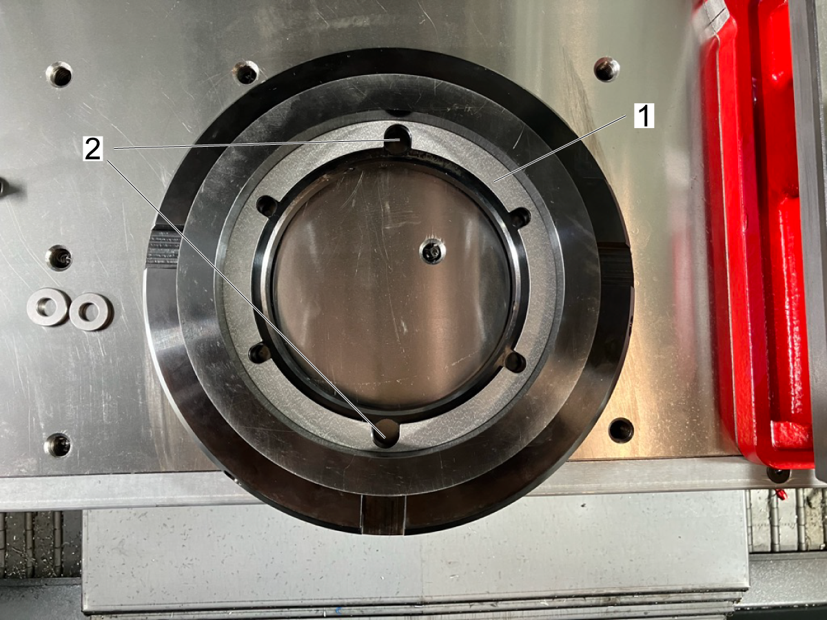
Install the shim stack [1] on the mounting plate (Figure 1).

Make sure that the two large cutouts in the shims are aligned with the two large through holes on the mounting plate [2] (Figure 1).

Slide the mounting plate over the spindle nose. Check for any inteferences with the coolant ring rail clamps.

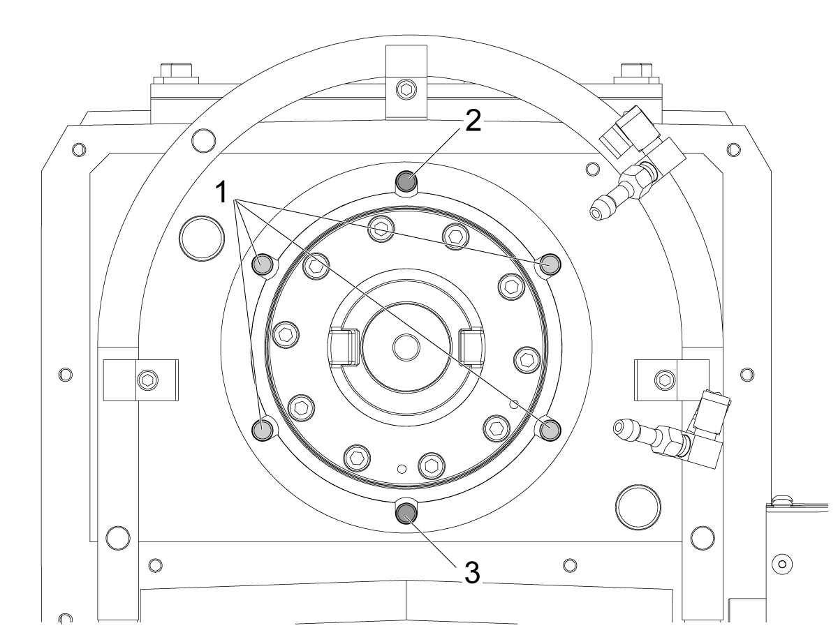
If the fit is satisfactory, remove 4 of the 3/8" mounting screws [1] and mark each with an X (Figure 2).

Do not remove the two bolts that are closest [2] and farthest [3] from the operator (Figure 2).

6

Slide the mounting plate and shim stack over the spindle nose. Use the provided longer length mounting bolts to secure the plate.

Tighten the plate until seated, then back off 1/8th of  a turn.

Installation

1

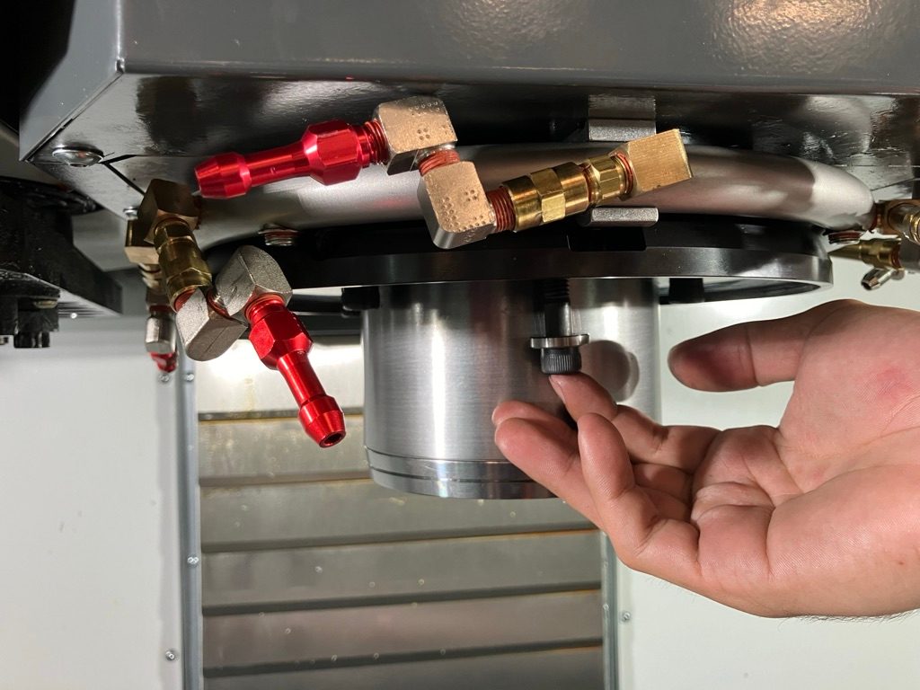
Install a tool into the spindle that allows a mag base to be attached and place the mag with an indicator to the tool.

Check that the plate is concentric with the spindle axis. Touch off the indicator on the inner rim of the plate, as shown. 

Check the runout of the plate  (NTE .002"). Use the set screws to adjust its position. A mallet may also be used to gently tap the high points on the sides of the plate.

Torque all of the bolts to 45 ft-lbs.

Remove the bolts closest and furthest from the operator and replace them with the provided bolts of longer length. 

2

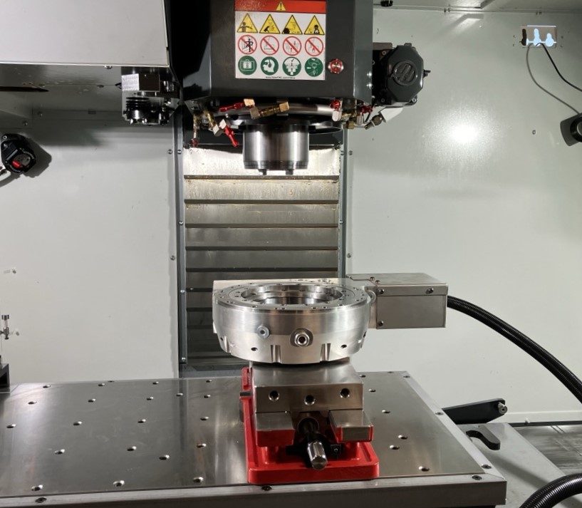
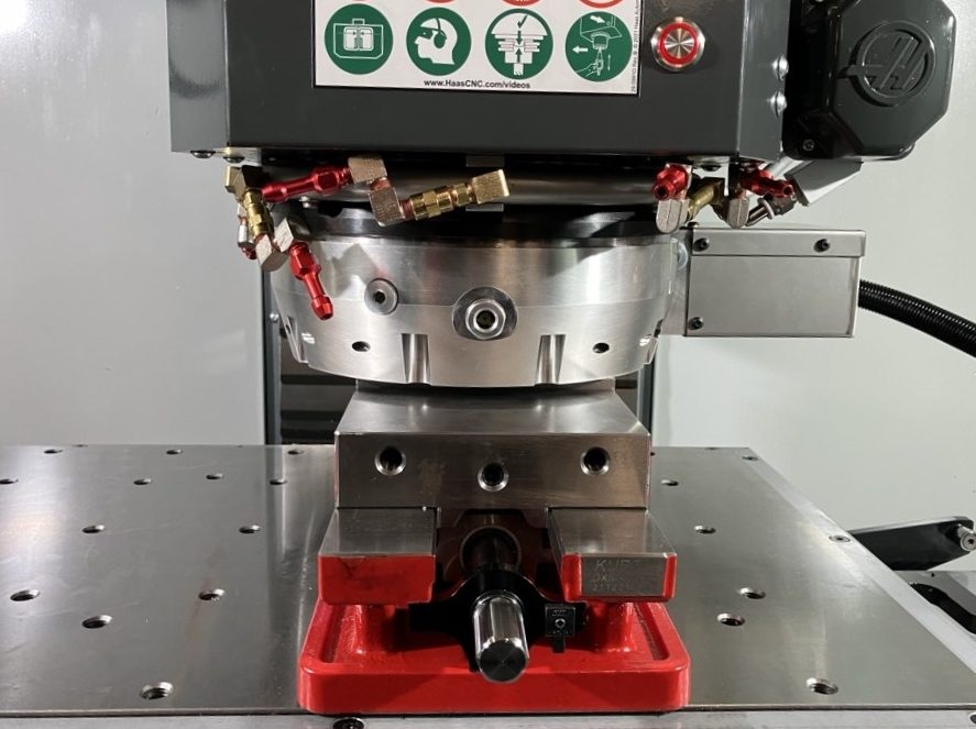
Use the three aluminum stock blocks or thte vice grip to prop up the drive on the table. Ensure that the drive assembly is properly centered on the blocks or vice grip.

Lower the Z-Axis into the center bore until M8 bolts have thread engagement and it is lowered to the lip.

Thread in the M8 bolts to draw in the drive assembly to the mounting plate.

Tighten the bolts until seated and then jog the Z-axis upwards.

Torque the M8 mounting bolts to 25 ft-lbs

3

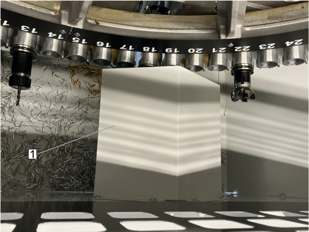
Before performing a tool change, remove the chip guard [1] from the tool changer enclosure by removing the four button-head screws. Replace the screws after removing the guard, to prevent chips from escaping. 

Electrical Installation

1

Remove the two button head screws [1] on the cable bracket located at the back of the enclosure of the machine.

2

Jog the X-Axis all the way to the right, and Y-Axis all the way back. Jog the Z-Axis down to the bottom of travel.

Route the conduit through the back of the enclosure [1]. Ensure the cable has enough slack, the cable should not be taut.

3

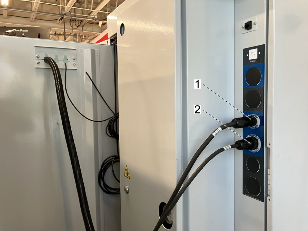
Plug Rotary Power Plug cable into plug labelled 4th Axis Power [1].

Plug Rotary Encoder Plug cable into plug labelled 4th Axis Encoder [2].

4

Press [SETTING].

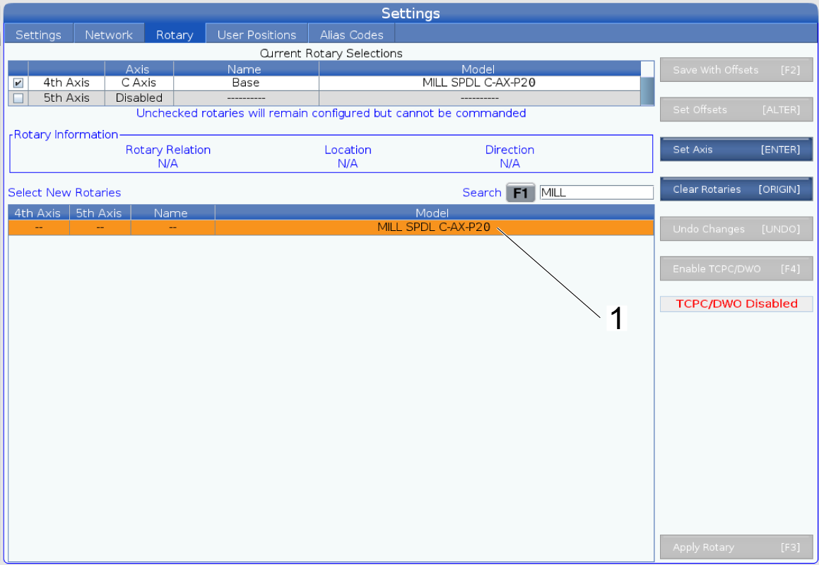
Navigate to the Rotary tab. Find setting MILL SPDL C-AX-P20 [1]. Press [ENTER] to set axis [2].  

Note: If the model does not appear, follow the instructions in 4 - Update Rotary Configuration Files - NGC_Rev_A. This procedure can be found in HBC.

5

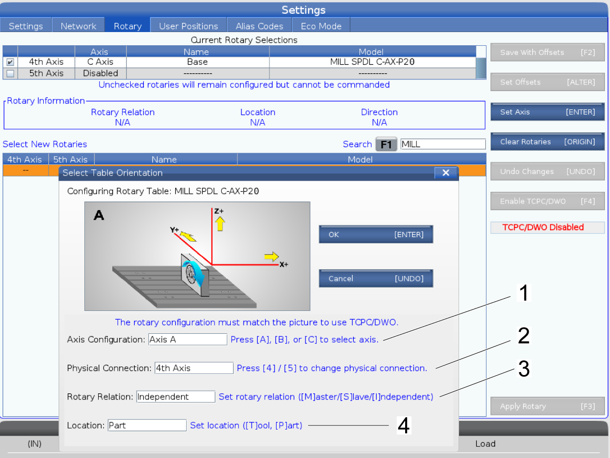
Set Axis Configuration to Axis C by pressing [C] [1].

Set Physical Connection to 4th Axis by pressing [4] [2].

Set Rotary Relation to Independent by pressing [I] [3].

Set Location to Tool by pressing [T] [4].


Set Grid and Tool Change Offsets

This section demonstrates how to set the tool change and grid offsets for the C-Axis drive. C-Axis drive tools are larger and more asymetrical than regular spindle tools. They must enter the tool changer in a certain orientation to prevent crashes. 

Warning: The grid and tool change offsets must be set correctly to prevent the machine from crashing during tool changes. 

1

Set Parameter 7.078 and Parameter 7.140 to zero. 

2

Press [C] + [ZERO RETURN] + [SINGLE] to enter the Zero Return page. Highlight each axis and press [F2] to zero it, until you reach the C-Axis. 


 Note: If this page does not appear, pull latest rotary paramters from HBC and try again. 


3

Handle jog the C-Axis and line up the center of the stopping block [1] with the notch closest to operator [2]. 


4

With the C-Axis highlighted [1], press [F2] [2] to zero return the C-Axis. 

 Note: If Alarm 165 Zero Return Margin is Too Small is generated, reset the alarm and proceed to the next step. 


5

Press [MDI] to exit the zero return page.

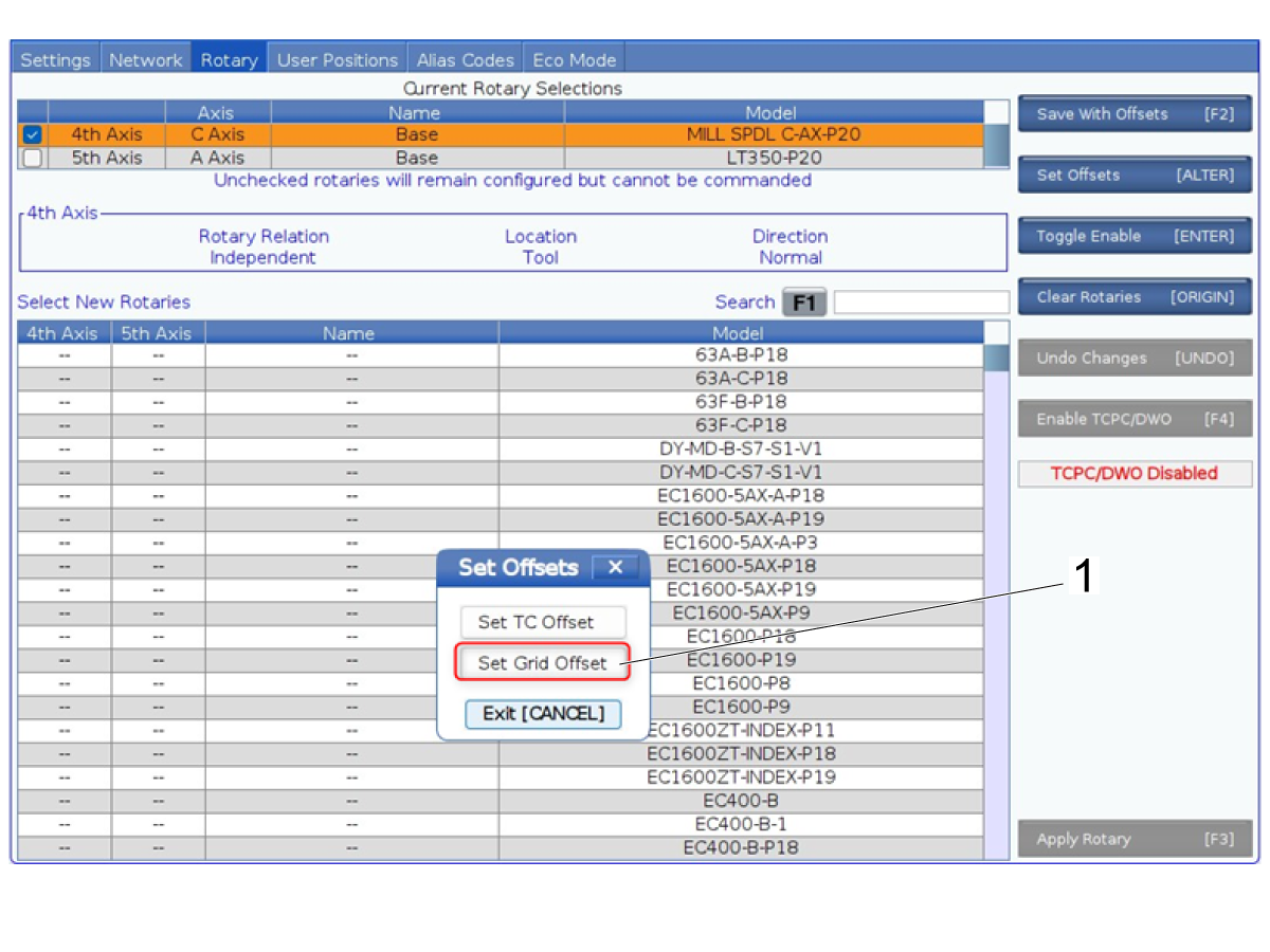
Press [SETTING]

Navigate to the Rotary tab. Highlight the 4th axis under Current Rotary Selections. Hit [ALTER] to set offsets. Select Set Grid Offset [1].

6

Press [C] + [ZERO RETURN] + [SINGLE] to enter the Zero Return page. Zero all axes. 

Highlight the C-Axis and press [HANDLE JOG]. Jog the C-Axis until the center of the stopping block [1] is realigned with the notch [2]. Press [F2] to zero return the C-Axis again. 


Jog to re-align C-Axis with the first notch again. This will be saved as the Tool Change Offset in the next step. 

7

Press [MDI] to exit the zero return page.

Press [SETTING]

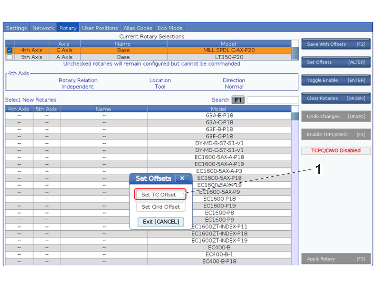
Navigate to the Rotary tab. Select the 4th axis under Current Rotary Selections. Hit [ALTER] to set offsets. Select Set TC Offset [1].

8

Press [C] + [ZERO RETURN] + [SINGLE] to enter the Zero Return page. Zero all axes. 

Press [F2] to zero return the C-Axis again. 

 Note: To zero return the C-Axis by itself, use Home G28 or another method. [C] + [ZERO RETURN] + [SINGLE] should only be used to set the home position. 


Calibrate Angle Head Tools

NOTE: The following steps outline a general procedure for calibrating angle head tools. This process will vary depending on the design of the tool. Use these steps only as a general guide.

1

Load your tool into the machine according to manufacturer instructions. 

2

Jog the tool until the C-Axis is at 0 and the tool is pointed to the right. 

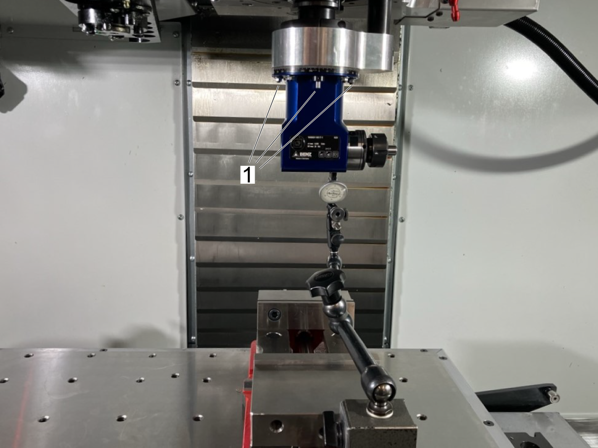
Loosen the screws at the base of the tool [1] so that the tool can rotate independently of the spindle. 

 NOTE: The angle head tooling pin should be oriented in this position before executing a tool change.

3

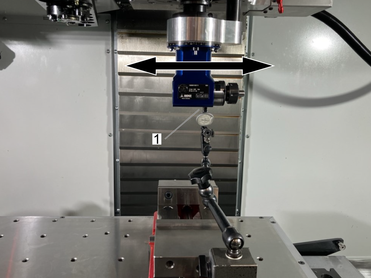
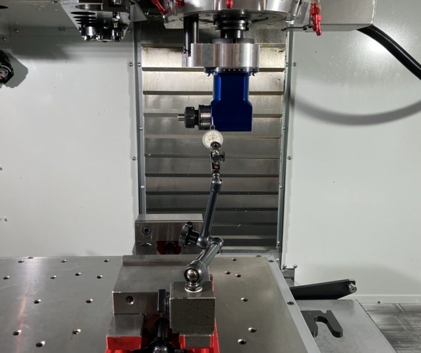
Place an indicator on the table and so that the needle is zeroed on the flat side on the back of the tool [1].

Jog the X-axis and check the parallelism of the tool.

Use a mallet to gently tap the tool to adjust until within the tolerance of 0.0005". 

Tighten the screws to lock the angle head into position. 

4

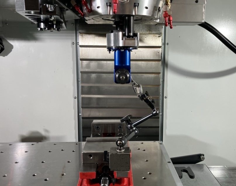
Handle jog the C-Axis to +90.

Check the parallelism on the same flat spot on the tool.


5

Take note of the C-Axis position.

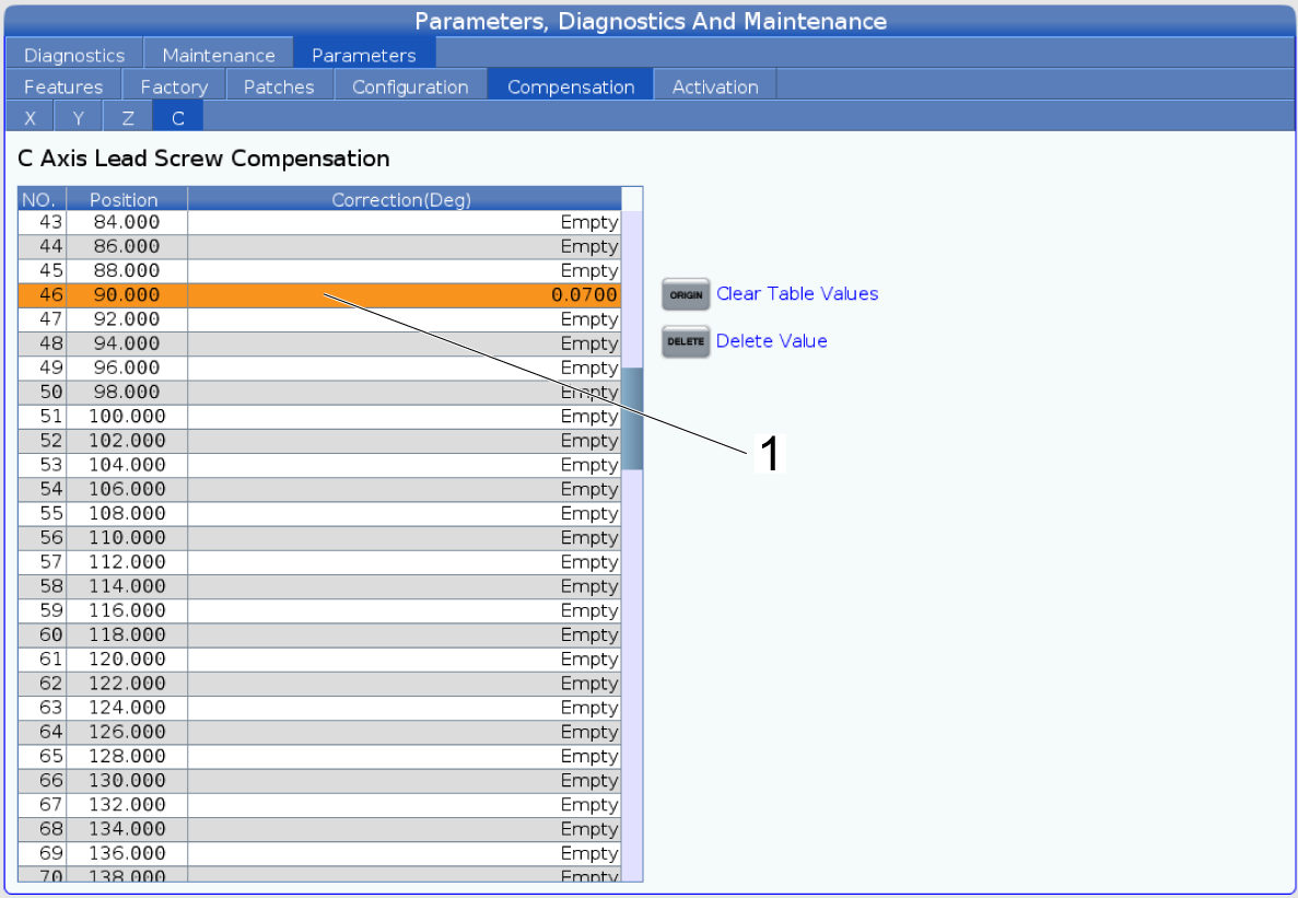
Press [DIAGNOSTIC] to open the Parameters, Diagnostics and Maintenance menu.

Navigate to the Parameters > Compensation > C tab. Navigate to the 90.000 position in the C Axis Lead Screw Compensation table [1]. Enter the C-Axis value. 

NOTE: Send the C-Axis to zero using G28 on the control.

Zero return C, then manually jog the C-Axis back to 90 and check the parallelism again.

If it is not within tolerance, note the position then add it to the existing compensation. Re-check the parallelism.

6

Repeat steps 2-4  for C-Axis positions at 180 and 270.

23.2 Mill - Spindle C-Axis Drive - Troubleshooting Guide

Recently Updated

Mill Spindle C-Axis Drive - Troubleshooting Guide


TG0175

Revision B - 07/2026

Introduction

This troubleshooting guide explains how to diagnose and resolve issues with a MIll Spindle C-Axis Drive.

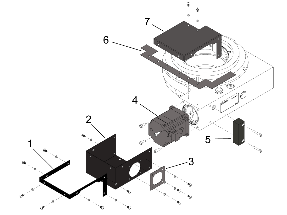
The top image shows the following components of the Mill Spindle C-Axis Drive

  1. Gasket Enclosure Cap 
  2. Enclosure Base
  3. Gasket Square J-box
  4. Servo Motor
  5. Enclosure Block
  6. Gasket Enclosure Base
  7. Enclosure Cap

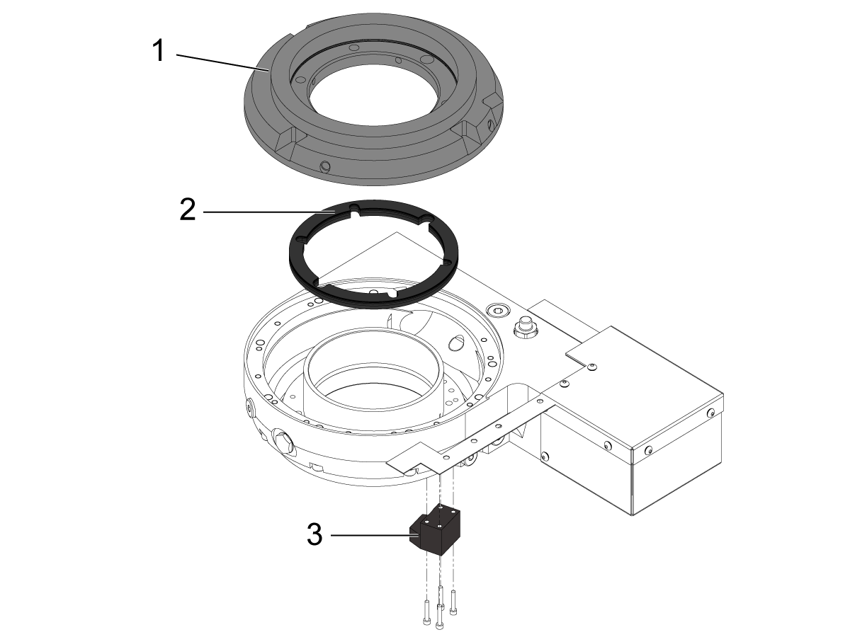
The bottom image shows the following components of the Mill Spindle C-Axis Drive

  1. Mounting Plate
  2. Shim Stack
  3. Tooling Stop Block

Required Software Versions:

1.21.000.1130 or higher

Rotary Files for VMC: 

  • Manual Rotary File: Mill SPDL C-AX-P20-V1
    • No Tool Tip Tracking available    
  • Automatic Rotary File: Mill SPDL C-AX-P20-V2
    • Tool Tip Tracking available 


Electrical Safety

DANGER: Working with the electrical services required for CNC machines is extremely hazardous and can result in serious injury or death.

Before connecting line wires to the CNC:

  • Turn off all power to the machine at the source.
  • Perform a Lockout-Tagout (LOTO) procedure to ensure the power remains off during service.
  • Verify that power has been disconnected by using an AC voltage detector on all incoming lines.

If you are uncertain about how to safely disconnect power or perform LOTO procedures:

  • Do not proceed.
  • Contact qualified personnel or obtain appropriate assistance before continuing.

Failure to follow these precautions may result in electrical shock, equipment damage, or fatal injury.

Danger: Before beginning any work inside the control cabinet, verify that the High Voltage indicator light on the 320V Power Supply / Vector Drive has been off for a minimum of five (5) minutes. This waiting period ensures that residual voltage has dissipated and reduces the risk of electric shock.

Certain service procedures involve high-risk electrical components and may pose serious injury or fatality hazards. Technicians must not attempt any procedure unless they have a complete understanding of the steps involved and the associated risks.

If there is any uncertainty regarding a procedure, contact your Haas Factory Outlet (HFO) to arrange for a qualified service technician.

Symptom Table

Symptom Possible Cause  Corrective Action


Alarm 7.108 C AXIS SERVO OVERLOAD

The feeds and speeds are too high for the work.  Decrease the feeds and speeds. 
The cutting tool is not sharp or is damaged.  Install a new device or a new tool insert. 
There is a mechanical blockage in the axis of travel.  Make sure the axis has a clear path of travel. 
The servo amplifier has a problem Troubleshoot the servo amplifier. 
Internal pressure is unable to escape  Email Haas Service.
Alarm 7.103 C AXIS SERVO ERROR TOO LARGE The connection to the encoder or power is faulty.  Check the encoder and power cable connections to the motor. 
The machined part has inaccurate features.  The feeds and speeds are too high for the work.  Decrease the feeds and speeds. 
The angle head tools were not properly calibrated   Refer to the Calibrate Angle Head Tools section in 23 - VF/VM - Spindle C-Axis Drive.

Alarm 175 GROUND FAULT DETECTED

Alarm 552 TRIPPED CIRCUIT BREAKER


There is a short to ground in the axis motor cable.  Test the axis motor cable for short. 
There is a short to ground in the axis motor.  Test the axis motor for short.

Alarm 7.9918 C AXIS SERIAL ENCODER INTERNAL DATA ERROR

Alarm 7.9922 C AXIS MOTION CHANNEL FAULT DETECTED

Alarm 7.9923 C AXIS SOFTWARE DETECTED ENCODER FAULT

Alarm 7.9930 C AXIS SERIAL ENCODER POOR COMMUNICATION

Alarm 7.9959 C AXIS SERIAL ENCODER DISCONNECT

Alarm 7.9948 C AXIS SECONDARY ENCODER SERIAL FAULT

Alarm 7.9949 C AXIS SOFTWARE DETECTED SECONDARY ENCODER FAULT

Alarm 7.9950 C AXIS SOFTWARE DETECTED SECONDARY ENCODER FAULT

Alarm 7.9951 C AXIS SECONDARY ENCODER SERIAL COMMUNICATION FAULT

Alarm 7.9960 C AXIS SECONDARY SERIAL ENCODER CABLE FAULT


The  software is outdated. 

Alarm is obsolete 

New alarm for encoder faults updated in software. Update to latest version 100.21.000.1130 or Higher;

Added Alarms 9719 and 9720 for Encoder Fault Detection on Mocon Primary and Secondary Axis.

Noise when the unit is moving.  Incorrect parameters NGC clear rotary models, cycle power and reselect the rotary model. 
no ferrites on the encoder and power cables.  Add ferrites to the encoder and power cable, and ensure the ferrite is not placed around the chassis ground cable. 
The unit crashed.  Contact HFO for repair options. 
Alarm 9961 INVALID OR MISSING ROTARY FILE is generated after the software update. 
Updated software to a version that does not include reverse rotary files while a reverse rotary file was enabled. 

Follow the Reverse Rotary Direction Setup - NGC procedure to install and activate reverse rotary files. 
Axis is commanded to move but does not move The motor is not operating.  Contact your HFO for repair options
Positioning or accuracy errors Machine level and geometry out of tolerance.   Have an HFO inspect the machine level and geometry and fill out a machine inspection report. Then, contact your HFO for repair options. 
Incorrect parameters enabled.  Make sure the correct set of parameters is in the machine. Then, make an error report and send it to Haas service. 
The rotary has crashed.  Contact your HFO for repair options. 
The angle head tools were not properly calibrated   Refer to the Calibrate Angle Head Tools section in 23 - VF/VM - Spindle C-Axis Drive.

Alarm 7.9719 C AXIS PRIMARY ENCODER SERIAL FAULT

Alarm Subcode (0x1) Encoder Data Fault = (Alarm 9918 SERIAL ENCODER INTERNAL DATA ERROR)

Encoder signals are affected by noise from high power cables.

(Faulty servo motor encoder.)

Refer to Serial Data Communication Faults / Electrical Noise section below.

(Check the servo motor for coolant contamination.)

Alarm 7.9719 C AXIS PRIMARY ENCODER SERIAL FAULT

Alarm Subcode (0x2) Encoder Internal Axis Fault 1 = (Alarm 9922 MOTION CHANNEL FAULT DETECTED)

(The motion channel has reported an internal fault of a type that is not recognized by the control)  Cycle power to the machine, If the issue persists, take an error report (Shift F3) and email to Haas Service

Alarm 7.9719  C AXIS PRIMARY ENCODER SERIAL FAULT

Alarm Subcode (0x3) Encoder Internal Axis Fault 2 = (Alarm 9923 SOFTWARE DETECTED ENCODER FAULT)

 (Software has reportrd an internal fault of a type that is not recognized by the control.)

 Cycle power to the machine. If the issue persists, take an error report (Shift F3) and email to Haas Service

Alarm 7.9719  C AXIS PRIMARY ENCODER SERIAL FAULT

Alarm Subcode (0x4) Encoder CRC Fault = (Alarm 9930 SERIAL ENCODER POOR COMMUNICATION)

 (Encoder signals are affected by noise from high power cables.)

 (Refer to Serial Data Communication Faults / Electrical Noise section below.)

Alarm 7.9719 C AXIS PRIMARY ENCODER SERIAL FAULT

Alarm Subcode (0x5) Encoder Cable Fault = (Alarm 9959 SERIAL ENCODER DISCONNECT)

 (Cables are not connected correctly or encoder is faulty.)

 (Inspect the cables and connectors. Refer to the Main Processor/Encoder Cable section below.)
Alarm 7.993 C AXIS AMPLIFIER SHORT CIRCUIT Coolant or liquid intrustion. Inspect the motor for short circuit condition and determine the cause. If it is found to be coolant related, replace the enclosure gasket on the servo motor housing or apply RTV sealant to holes.
Note: Be sure the RTV sealant has enough time to cure before coolant may come in contact with the rotary.

C-Axis Drive Check Valve

Updated

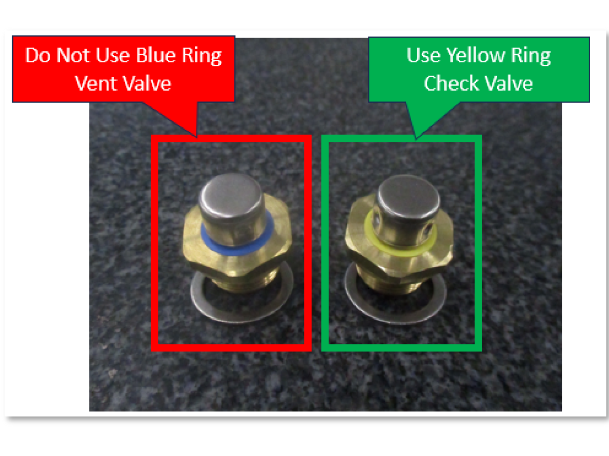
Early models of the C-Axis drive saw servo motor overload and poisition error too large alarms due to pressure buildup. A breather valve was added to the design to resolve this issue for future models. If the breather value  [1] is not installed, contact Haas Service for assitance.

Note: Some models may come with a valve that has a blue ring attached DO NOT USE the valve with the blue ring as it does not protect the oil cavity from coolant intrusion. Use the valve with the yellow ring instead PN 93-6587. 

WIPS-IR Minimum Tool Length

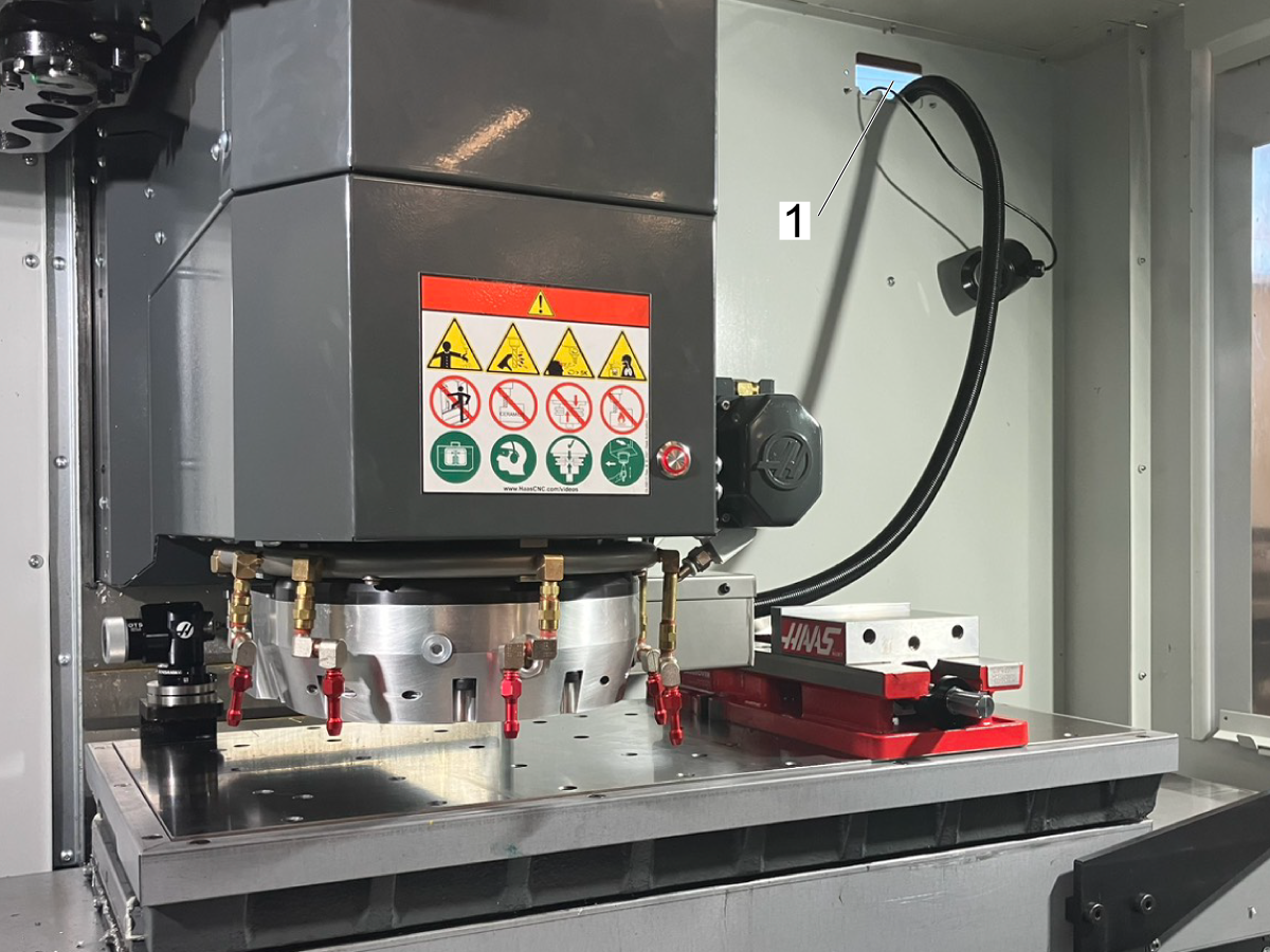
When installing the C-Axis option, existing WIPS-IR has probing limitations because the C-Axis electrical box protrudes too far and blocks the probe's line of sight.

The Optical Machine Interface can be moved downward (as shown in top image) to restore line of sight. However, there is a minimum tool length required before the Optical Machine Interface becomes obstructed by the electrical box. 

The bottom image shows the new 10.5" PN 93-1000025 [1] and 2.5" PN 93-1000026 [2] probe riser kits, which reduce the minimum tool length required to maintain line of sight.

Note: This issue does not apply to the WIPS RF option as it communicates via radio frequency and does not require line of sight.


Serial Data Communication Faults / Electrical Noise

Sigma-5 servo motors, non-contact encoders output serial data signal to the control. If the serial data signal is missing or becomes unreliable the control will generate a serial data communication error. Electrical noise can cause the serial data signal from the encoder to become unreliable and cause false alarms. Follow the troubleshooting guide below to help eliminate the noise in the system.

  1. Incorrect machine grounding. Make sure the ground wire size is correct. Also the ground wire should run all the way back to the electrical panel.
  2. Noise from other equipment. Make sure the machine does not share it's electrical service with another machine.
  3. Loose encoder data connectors at PCB or at the motor encoder, can cause the serial data to become unreliable. Refer to the Main Processor / Encoder Cable section.
  4. Loose ground or high voltage power connectors will induce noise into the system.
    • electrical cabinet check for loose connection at all the ground and high voltage power terminals (vector drive, wye-delta contactors, transformer..etc).
    • pendant check for loose terminal connectors.
    • spindle head check for loose ground and motor power terminals.
  5. The ferrite filters suppress high frequency noise produced by the amplifiers and vector drive, when servos are on. Make sure they are installed in:
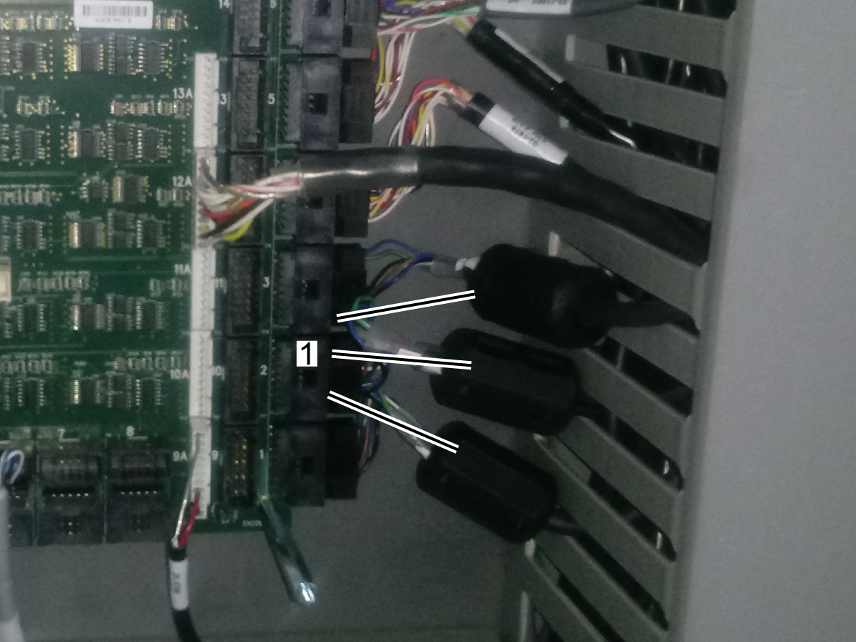
    • Encoder data cables. Make sure there is a ferrite filter P/N 64-1252 installed in all the encoder data cables.
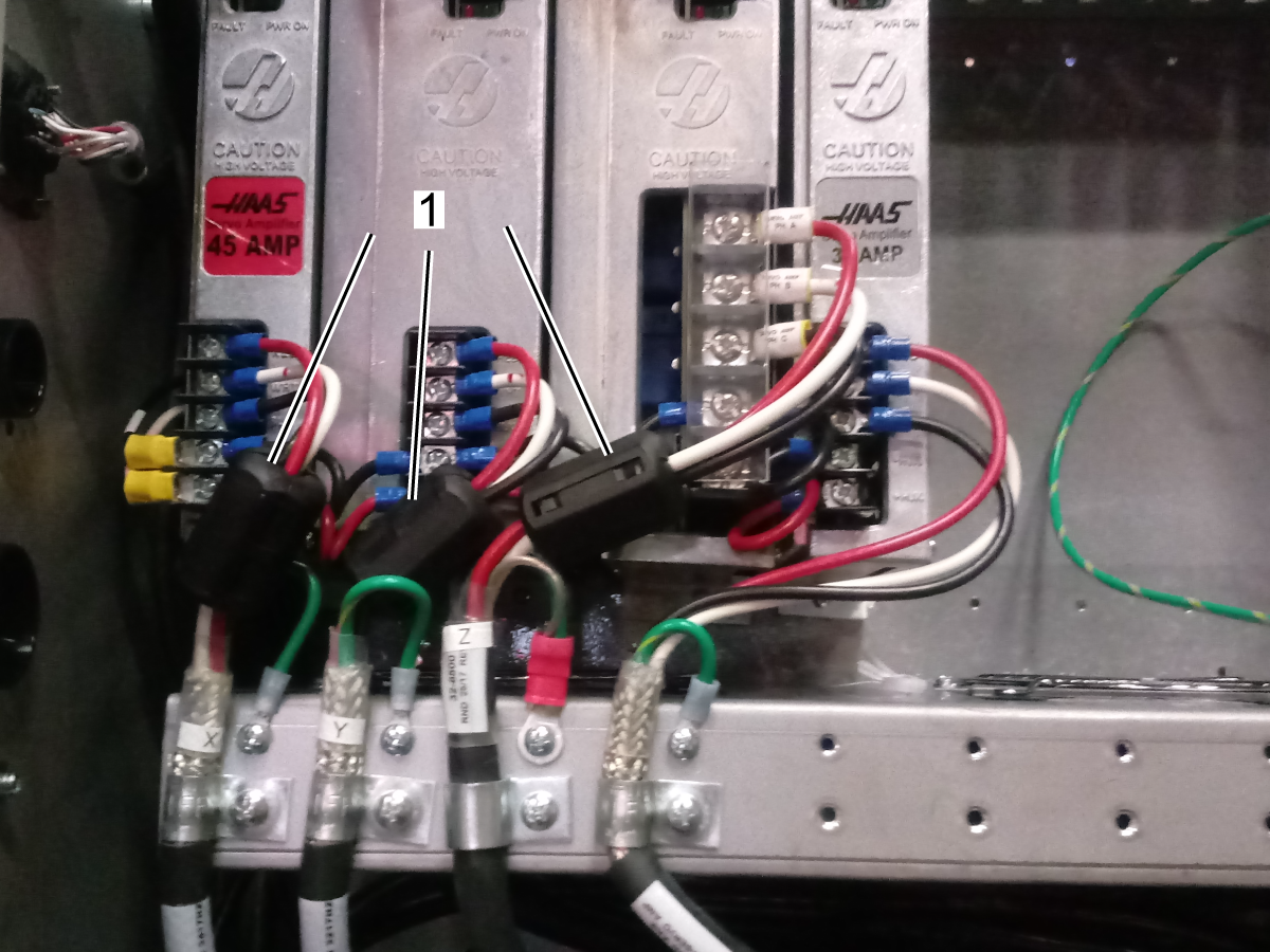
    • Axis motor power cables. Make sure there is a ferrite filter P/N 64-1252 installed in X, Y, Z axis motor power cables [1].
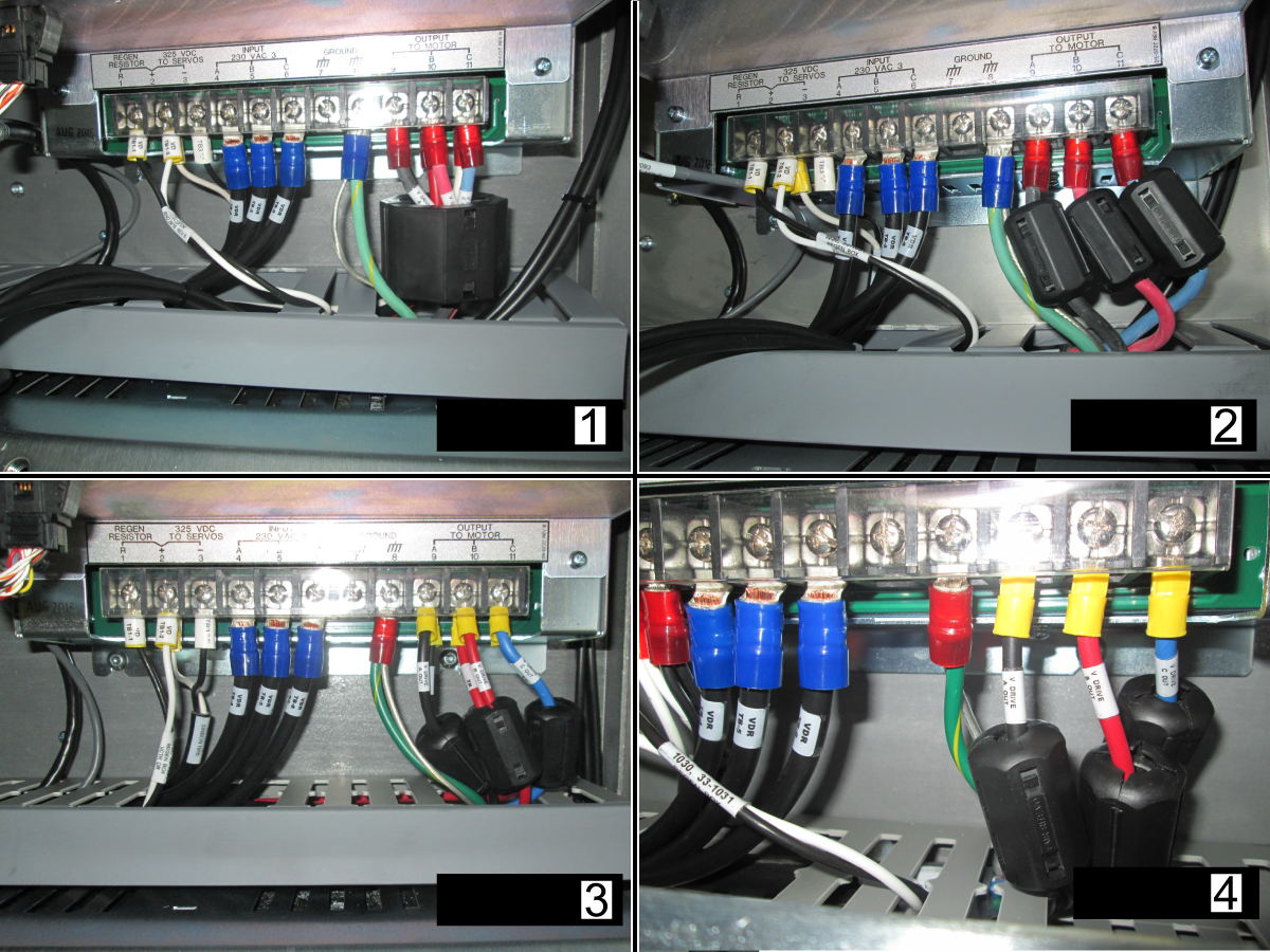
    • Spindle motor cables. Make sure there is a ferrite filter installed in the motor output of the vector drive.

      For a 40HP vector with 6 wire leads [1] use ferrite P/N 64-1254.

      For a 40HP vector with 3 wire leads [2] use ferrite P/N 64-1252.

      For a 20HP vector drive with 6 or 3 wire leads [3, 4] use ferrite P/N 64-1252.

  6. Cable routing. Make sure that the encoder cable is separated from high power spindle/axis/pump cables.

Maincon PCB / Encoder Cable

Corrective Action:

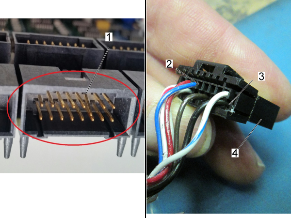
Examine the connector [1] on the Maincon. Make sure it is not damaged.

Examine the cable. Look for signs of damage or stiffness. The connector [4] has two housings [2,3] for the cable pins.

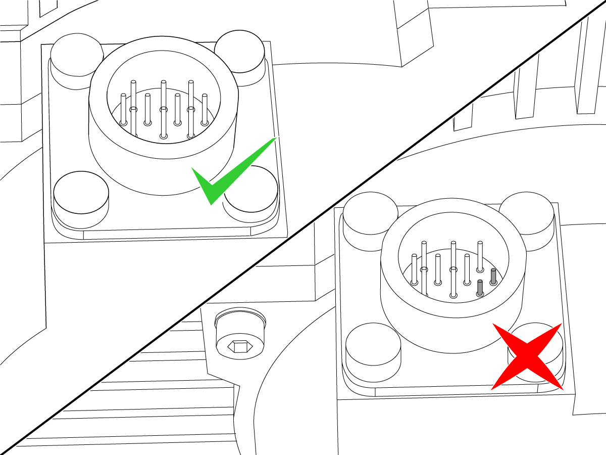
If the pins have been pushed into the motor, you must replace the motor and cable together.

Make sure the cable is firmly connected at both ends. Reseat both connections. Make sure the cable is installed in the correct connector at the Maincon or MOCON PCB.

Electrical Diagram

Recently Viewed Items

You Have No Recently Viewed Items Yet

Recently Viewed Items

You Have No Recently Viewed Items Yet

Feedback
Haas Logo

Haas Delivered Price

This price includes shipping cost, export and import duties, insurance, and any other expenses incurred during shipping to a location in France agreed with you as a buyer. No other mandatory costs can be added to the delivery of a Haas CNC Product.

KEEP UP WITH THE LATEST HAAS TIPS AND TECHNOLOGY...

Sign up now!   

HAAS TOOLING ACCEPTS THE FOLLOWING:

  • Service & Support
  • Owners
  • Request Service
  • Operator Manuals
  • Haas Parts
  • Rotary Repair Request
  • Pre-Install Guides
  • Shopping Tools
  • Build & Price a New Haas
  • Available Inventory
  • The Haas Price List
  • CNCA Financing
  • About Haas
  • Accessibility Statement
  • DNSH Statement
  • Export Compliance
  • Careers
  • Certifications & Safety
  • Contact Us
  • History
  • Terms & Conditions
  • Haas Tooling Terms & Conditions
  • Privacy
  • Warranty
  • Haas Community
  • Haas Certification Program
  • Haas Motorsports
  • Gene Haas Foundation
  • Haas Technical Education Community
  • Events
  • Join the Conversation
  • Facebook
  • X
  • Flickr
  • YouTube
  • LinkedIn
  • Instagram
  • TikTok
© 2026 Haas Automation, Inc – CNC Machine Tools
This site is protected by reCAPTCHA and the Google Privacy Policy and Terms of Service apply.

2800 Sturgis Rd., Oxnard, CA 93030
Toll Free: (888) 817-4446 / Fax: 805-278-8554