×

Search Results

Web Pages

Images

    • <
    • 1
    • >
  • machines
    • Haas Vertical Mills
      Vertical Mills
      • Vertical Mills
      • VF Series
      • Universal Machines
      • VR Series
      • Pallet-Changing VMCs
      • Mini Mills
      • Mold Machines
      • Drill/ Tap/ Mill Series
      • Toolroom Mills
      • Compact Mills
      • Gantry Series
      • Vertical Mill/Turn
      • Extra-Large VMC
      • Double-Column Mills
      • Desktop Mill
      • Mill Auto Parts Loader
    • Product Image
      Multi-Axis Solutions
      • Multi-Axis Solutions
      • Y-Axis Lathes
      • 5-Axis Mills
    • Haas Lathes
      Lathes
      • Lathes
      • ST Series
      • Dual-Spindle
      • Toolroom Lathes
      • Chucker Lathe
      • Haas Bar Feeder V2
      • Lathe Auto Parts Loader
    • Haas Horizontal Mills
      Horizontal Mills
      • Horizontal Mills
      • 50-Taper
      • 40-Taper
    • Haas Rotaries & Indexers
      Rotaries & Indexers
      • Rotaries & Indexers
      • Rotary Tables
      • Indexers
      • 5-Axis Rotaries
      • Extra-Large Rotaries
    • Product Image
      Automation Systems
      • Automation Systems
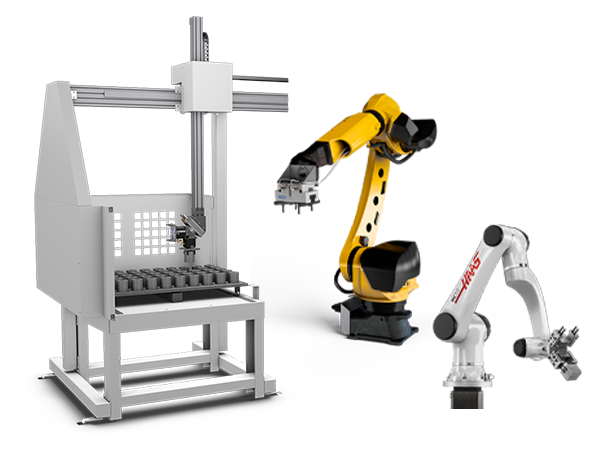
      • Robot Systems
      • Automatic Parts Loaders
      • Pallet-Pool Systems
      • Haas Bar Feeder
      • Models
    • QUICK LINKS Special Series  Special Series 
      HAAS CAREERS HAAS CAREERS BUILD & PRICE BUILD & PRICE PRICE LIST PRICE LIST WHAT’S NEW WHAT’S NEW YOUR FIRST CNC YOUR FIRST CNC HAAS SIX PACK HAAS SIX PACK
      SHOPPING TOOLS
      • Build & Price a Haas
      • Price List
      • Available Inventory
      • CNCA Financing
      WANT TO TALK TO SOMEONE?

      A Haas Factory Outlet (HFO) can answer your questions, and walk you through your best options.

      CONTACT YOUR DISTRIBUTOR >
  • Options
    • Product Image
      Spindles
      • Spindles
    • Product Image
      Tool Changers
      • Tool Changers
    • Product Image
      4th- | 5th-Axis
      • 4th- | 5th-Axis
    • Product Image
      Turrets & Live Tooling
      • Turrets & Live Tooling
    • Product Image
      Probing
      • Probing
    • Haas Chip & Coolant Management
      Chip & Coolant Management
      • Chip & Coolant Management
    • The Haas Control
      The Haas Control
      • The Haas Control
    • Product Image
      Product Options
      • Product Options
    • Product Image
      Tooling & Fixturing
      • Tooling & Fixturing
    • Product Image
      Workholding
      • Workholding
    • Product Image
      5-Axis Solutions
      • 5-Axis Solutions
      • 5 Easy Steps to 5-Axis
    • Product Image
      Automation
      • Automation
    • QUICK LINKS Special Series  Special Series 
      HAAS CAREERS HAAS CAREERS BUILD & PRICE BUILD & PRICE PRICE LIST PRICE LIST WHAT’S NEW WHAT’S NEW YOUR FIRST CNC YOUR FIRST CNC HAAS SIX PACK HAAS SIX PACK
      SHOPPING TOOLS
      • Build & Price a Haas
      • Price List
      • Available Inventory
      • CNCA Financing
      WANT TO TALK TO SOMEONE?

      A Haas Factory Outlet (HFO) can answer your questions, and walk you through your best options.

      CONTACT YOUR DISTRIBUTOR >
  • Why Haas
      Discover the Haas Difference
      Why Haas MyHaas Education Community Industry 4.0 Haas Certification Customer Testimonials
  • Service
      Welcome to Haas Service
      SERVICE HOME Operator’s Manuals How-To Procedures Troubleshooting Guides Preventive Maintenance Haas Parts Haas Tooling Videos
  • Videos
  • Haas Tooling
      Haas Tooling Mill Toolholding Mill Workholding Milling Lathe Tooling Lathe Toolholding Lathe Workholding ER Collets & Chucks Holemaking Threading Tool Management Tooling Accessories Package Kits Measuring & Inspection Apparel & Accessories
      HAAS TOOLING QUICK LINKS
      NEW PRODUCTS NEW PRODUCTS
      MOST POPULAR MOST POPULAR
      OPEN TERMS OPEN TERMS
      FINANCING FINANCING
      FAQs FAQs
      KITS CREATED FOR YOU KITS CREATED FOR YOU
  • Haas Service Parts
      Haas Service Parts Automatic Pallet Changer Automatic Tool Changer Chip Management Coolant Counterbalance Electrical Cabinet Enclosure Field Install Options Hydraulics Lubrication Maintenance Pendant Probing Rotary Spindle Tailstock
  • Contact Us

My Cart
MyHaas Welcome,
!
Haas Tooling Guest Order History MyHaas/HaasConnect Sign In Register Haas Tooling My Account Order History Return History MyHaas/HaasConnect Sign Out Welcome, My Machines Latest Activity My Quotes My Account My Users Sign Out
Find A Dealer
  1. Select Language
    1. English
    2. Deutsch
    3. Español
    4. Français
    5. Italiano
    6. Português
    7. Český
    8. Dansk
    9. Nederlands
    10. Magyar
    11. Polski
    12. Svenska
    13. Русский
    14. Türkçe
    15. 中文
    16. Suomi
    17. Norsk
    18. الإنجليزية
    19. български
    20. Hrvatski
    21. Ελληνικά
    22. Română
    23. Slovenský
    24. Slovenščina
    25. 한국어
    26. 日本語
Search
×

Search Results

Web Pages

Images

    • <
    • 1
    • >

11 - VF/VM - 40T - Gearbox

VF/VM-Series - Service Manual


  • 1 - VF/VM - Introduction
  • 2 - VF/VM - Specifications
  • 3 - VF/VM - Installation
  • 4 - VF/VM - Umbrella Tool Changer
  • 5 - VF/VM - HSK - SMTC
  • 6 - VF/VM - 40T/50T - SMTC
  • 7 - VF/VM - Axis Motion
  • 8 - VF/VM - HSK - Spindle
  • 9 - VF/VM - 40T - Spindle
  • 10 - VF/VM - 40T - Spindle Motor
  • 11 - VF/VM - 40T - Gearbox
  • 12 - VF/VM - 50T - Spindle
  • 13 - VF/VM - 50T - Gearbox
  • 14 - VF/VM - Lubrication Systems
  • 15 - VF/VM - Electrical Control
  • 16 - VF/VM - Chip Removal and Coolant
  • 17 - VF/VM - Workholding
  • 18 - VF/VM - Maintenance
  • 19 - VF/VM - Autodoor
  • 20 - VF/VM - Robot and Automation
  • 21 - VF/VM - Enclosure

Go To :

  • 11.1 40T - Gearbox - Replacement
  • 11.2 40T - Gearbox Troubleshooting
  • 11.3 40T - Gearbox - Oil Change

40-Taper - CALM - Gearbox - Replacement

1

Push [POWER OFF]. Set the main circuit breaker to the OFF position.

Lock the main circuit breaker. Use an approved lock with an approved safety tag. Close the primary air valve.

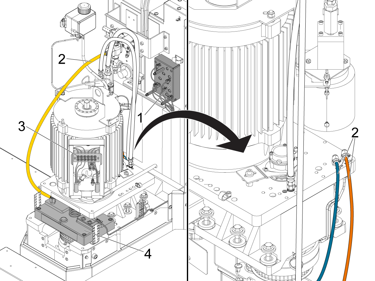
Remove all the electrical [1] and pneumatic [2] connections from the gearbox assembly. Put marks to record their locations. Put labels on all cables and hoses.

Record the wiring configuration for the spindle motor [3]. Disconnect the wires. Remove the tool release piston (TRP) [4]. If the machine has through-spindle coolant (TSC), disconnect the necessary plumbing.

2

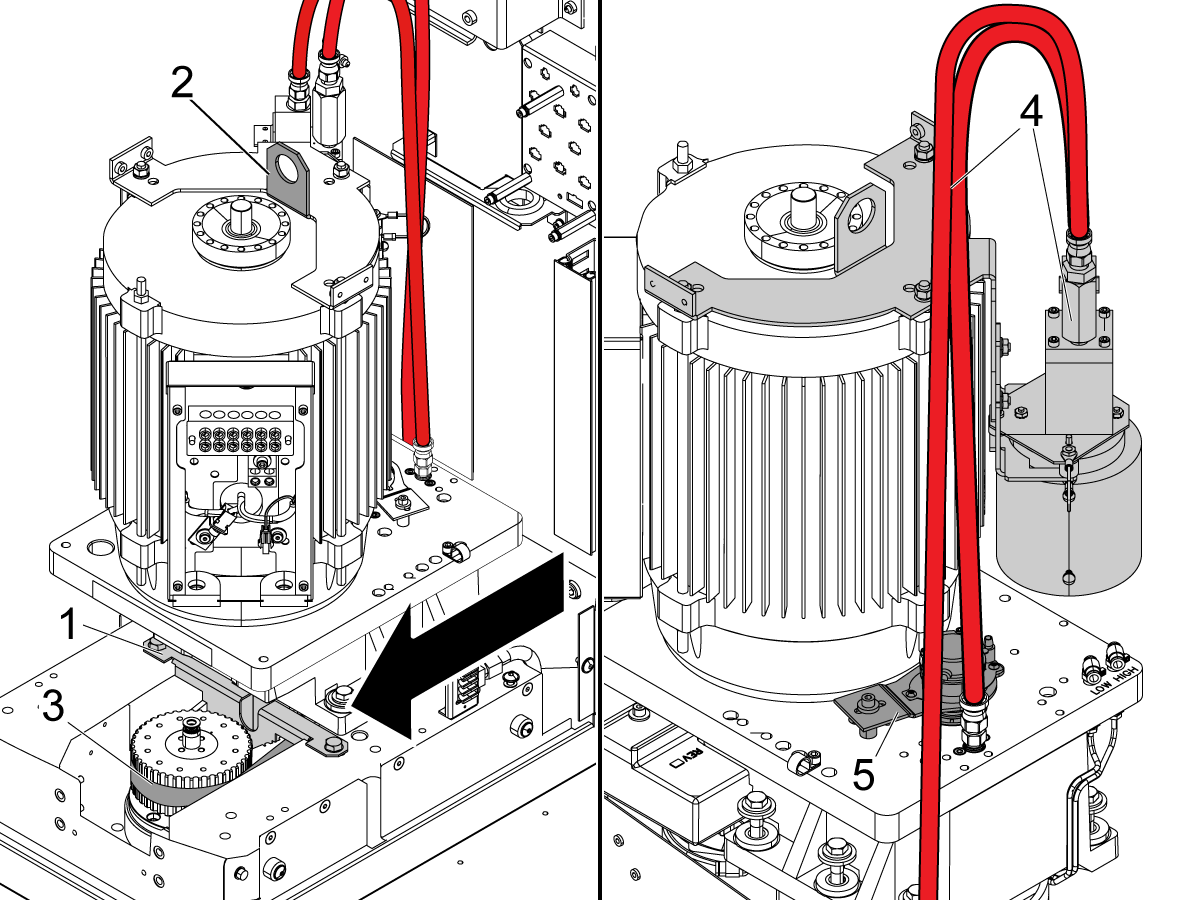
If the gearbox has a mid belt shield [1], remove it.

Make sure no cables are connected to the gearbox. Remove the gearbox from the machine.

Remove (5) of the (6) bolts from the gearbox assembly. Do not remove (1) of the bolts near the rear of the machine. Loosen this (1) remaining bolt. With your hands, pull the gearbox toward the spindle. This loosens the tension on the spindle belt [3]. Connect the hoist to the gearbox [2]. Lift the hoist until it supports the gearbox. Remove the (1) remaining bolt from the gearbox assembly. Slowly lift the gearbox.

Remove the gearbox from the machine. Move the transmission oil pump assembly [4] and the spindle encoder [5] to the new gearbox.

3

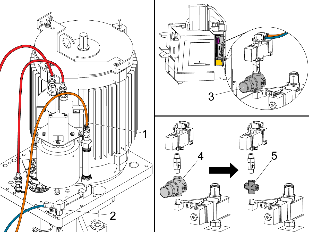
Connect the high-gear air hose [1] from the CALM cabinet to the fitting on top of the air-over-oil assembly.

Connect the low-gear hose [2] to the fitting on the top plate of the gearbox labeled LOW.

If you have a 35-psi air regulator [3] on the input of the shift solenoid in the CALM cabinet, you must remove it. Replace the 35-psi air regulator [4] with the tee fitting [5].

If you have an adjustable air regulator on the input of the shift solenoid, set the air regulator to 80 psi.

4

Replace the spindle drive belt if necessary. Install the new gearbox. Set the correct tension on the spindle drive belt. Refer to VMC - Drive Belt Tension - Gates Sonic Meter - Instructions. Install the components from the used gearbox in the opposite sequence that you removed them.

Torque the screws in a star pattern. Refer to Haas Fastener Torque Specifications. Use the value for iron.

Connect the cables and hoses you removed from the old gearbox. Make sure you have the correct wiring configuration for the spindle motor. If necessary, refer to Spindle Motor - Wiring Configurations.

40 Taper Gearbox Lubrication System

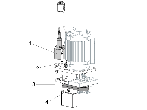
Gearbox Assembly Diagram

40-taper Gearbox

  1. Gearbox oil pump
  2. High gear shifter oil tube
  3. Spindle drive belts
  4. High/low gear proximity sensors or mechanical switches

Exploded View 40T

  1. SPINDLE MOTOR 10HP LINCOLN
  2. GEAR 16DP 40 TOOTH 2.05"
  3. FITG JIC-5-F X -5 HOSE STR
  4. RETAINING RING 1.875 INT BASIC
  5. SHCS 5/16-18 X 1
  6. GEARBOX TOP PLATE 16DP-65T
  7. HHB 1/2-13 X 1 3/4 GRADE 8 PLAIN
  8. SPRING BELVIL 1.206ID X 1.831OD X 0.059
  9. BEARING M17-47-14 OIL
  10. GEARBOX TRANSFER GEAR ASSY 16DP65T
  11. NUT 7/16-20, LOCKING
  12. SHIFT FORK 40T GEARBOX
  13. BEARING M25-47-12
  14. RETAINING RING 1.000 EXT BASIC
  15. RETAINING RING 0.669 EXT BASIC
  16. HOUSING GEARBOX MACHINED
  17. FITG HOSE BARB3/8 NPT1/4M 90 BRASS
  18. SHCS 10-32 X 7/8
  19. SPROCKET
  20. SHIFTER SHAFT
  21. QUAD-RING Q4-114 VITON NOT FOR SALE
  22. SHIFTER BODY
  23. SHCS 10-32 X 2
  24. 40T SWITCH MOUNTING BRACKET
  25. PICK UP TUBE DRY SUMP
  26. SHCS 1/4-20 X 1/2 ZINC
  27. SHCS 10-32 X 3/8 W/ FLAT WASHER OD 0.37-
  28. NIPPLE 1/2 NPT X 4 1/2 BRASS
  29. FITG HOSE BARB1/4 NPT1/4M STR BRASS
  30. FITG PC1/4F NPT1/8M 90 STL
  31. ENCODER SPRING MOUNT
  32. S SEAL 26MM ID X 52MM OD X 8MM
  33. RETAINING RING 2.047 INT BASIC
  34. SHCS 10-32 X 1 1/4
  35. GEARBOX GEAR LUBE MANIFLOD 16DP-40T
  36. GEARBOX GEAR LUBE MANIFLOD CONN TUBE
  37. GEARBOX GEAR LUBE MANIFLOD 16DP-32T
  38. SPRING BELVIL 1.403ID X 2.028OD X 0.059
  39. BEARING M25-52-15 OIL
  40. GEARBOX DRIVE GEAR ASSY 16DP65T
  41. BEARING M30-72-19 OIL
  42. F SEAL 1.125 X 1.595 X 0.240 F
  43. VIBRATION ISOLATOR UPPER
  44. SPACER
  45. VIBRATION ISOLATOR LOWER
  46. OIL CATCH PAN
  47. HIGH GEAR TUBE 40T GEARBOX-Co R0.438"
  48. PROXIMITY SENSOR
  49. DRAIN TUBE DRY SUMP
  50. F SEAL 0.875 X 1.345 X 0.350 F
  51. SUMP BRACKET
  52. SUMP TANK

Symptom Table

Symptom Possible Cause Corrective Action

Alarm 4.126 GEARBOX FAULT

Insufficient air volume. Make sure that air supply meets the requirements, and check for leaks.
The high or low gear status sensor is faulty. Troubleshoot the sensors.
The high or low gear solenoid is faulty. Troubleshoot the solenoid.
Damaged gearbox. Make sure the gearbox shifts when applying air to it.
Shift dampener installed. Remove the shift dampener.
Alarm 4.126 GEARBOX FAULT intermittently generated on machines built with a digital SMC gearbox solenoid There is a small delay when the solenoid is commanded, thus causing the alarm to generate. Order service kits 93-3450 & 93-3452 and follow the Low Load Solenoid Valve Kit - Installation procedure.
Alarm 4.2011 LOW GEARBOX OIL LEVEL The oil level is low. Fix the leaks and refill with oil.
The NGC software is outdated.
Starting in NGC software version 100.17.000.2045 to 100.19.000.1003 the control only monitors the gearbox oil level condition at power-on. Once the gearbox low oil condition is detected, the icon will clear on the next power on when a normal level condition is detected.  If you are getting a Low Gearbox Oil icon during machine operation, make sure you update the software to 100.17.000.2045 or higher.  Too much oil will cause a leak,  drain the oil and fill with the correct amount.

Note:  In software version 100.19.000.1102 and higher the gearbox oil level is checked continuously when the spindle fan is off.  After the spindle fan turns off, there is a delay before gearbox oil level monitoring begins.  Press the [RESET] to clear the low gearbox oil icon.
Oil level switch is faulty. Troubleshoot the oil level switch.
Orifices getting clogged causing a leak. Blow air through the orifices to unclog, 
Sump tank missing weep hole and a change to foam gasket.  Drill the weep hole on the backside (encoder side) of the sump tank. Clean thoroughly after drilling to not introduce debris.
Alarm 4.2012 LOW GEARBOX OIL FLOW The oil level is low. Fix the leaks and refill with oil.
There is a clog in the oil-pump inlet screen. Clean the inlet screen.
There is a problem with the oil flow switch. Troubleshoot the oil flow switch.
The oil-pump motor does not receive power. Troubleshoot the oil-pump motor.
There is a problem with the oil-pump motor gears or coupler. Inspect the gears or coupler.
Faulty P-Tech oil pump If the machine was manufactured before August of 2019 and the gearbox oil pump is a P-Tech P/N TTM-0669, replace the oil pump.  Note:  Do not replace the P-Tech pump if the P/N does not match the one mentioned above.
Orifices getting clogged causing a leak. Blow air through the orifices to unclog, 
On a machine with a NGC control:  A Low Gearbox Oil icon appears during machine operation. The NGC software is outdated. Starting in NGC software version 100.17.000.2045 to 100.19.000.1003 the control only monitors the gearbox oil level condition at power-on. Once the gearbox low oil condition is detected, the icon will clear on the next power on when a normal level condition is detected.  If you are getting a Low Gearbox Oil icon during machine operation, make sure you update the software to 100.17.000.2045 or higher.  Too much oil will cause a leak,  drain the oil and fill with the correct amount.

Note:  In software version 100.19.000.1102 and higher the gearbox oil level is checked continuously when the spindle fan is off.  After the spindle fan turns off, there is a delay before gearbox oil level monitoring begins.  Press the [RESET] to clear the low gearbox oil icon.
Sump tank missing weep hole and a change to foam gasket.  Drill the weep hole on the backside (encoder side) of the sump tank. Clean thoroughly after drilling to not introduce debris.
Noisy Gearbox  The oil level is low.
Fix the leaks and refill with oil. Fix the leaks and refill with oil.
The drive belts are worn or incorrectly adjusted. Set the belt tension.
The encoder feedback is faulty. See the Excessive Gearbox Noise section below.
Damaged or worn out encoder pulley or encoder belt. Inspect the encoder pulley.
Run-out or play within the encoder. Check for runout or play.
The gears are damaged. Perform a vibration analysis.
High Load Bad connection at the Wye/Delta contactor. Troubleshoot Wye/Delta assembly.
Oil leaking from output shaft. Sump tank missing weep hole and a change to foam gasket.  Drill the weep hole on the backside (encoder side) of the sump tank. Clean thoroughly after drilling to not introduce debris.

Drive Belts

Corrective Action:

Check for damage to the pulleys. Check the drive belts for wear and correct tension.

High/Low Gear Sensors

Corrective Action:

Check for contamination of the connectors. Reseat the connections.

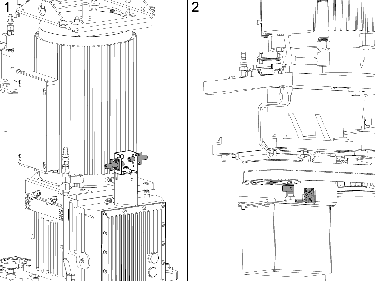
Make sure the sensor is tight on the bracket and gearbox. Image shows a 50T [1] and 40T [2].

Refer to the Proximity Sensor - Troubleshooting Guide.

High/Low Gear Solenoid

Corrective Action:

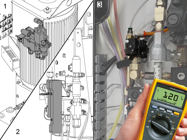
Use a voltmeter to check for 120 VAC at the solenoid.

The solenoid may be located on the 50T gearbox [1], the 40T gearbox [2] or in the CALM cabinet [3].

Refer to the Solenoid - Troubleshooting Guide.

Oil Pump Gears/Coupler

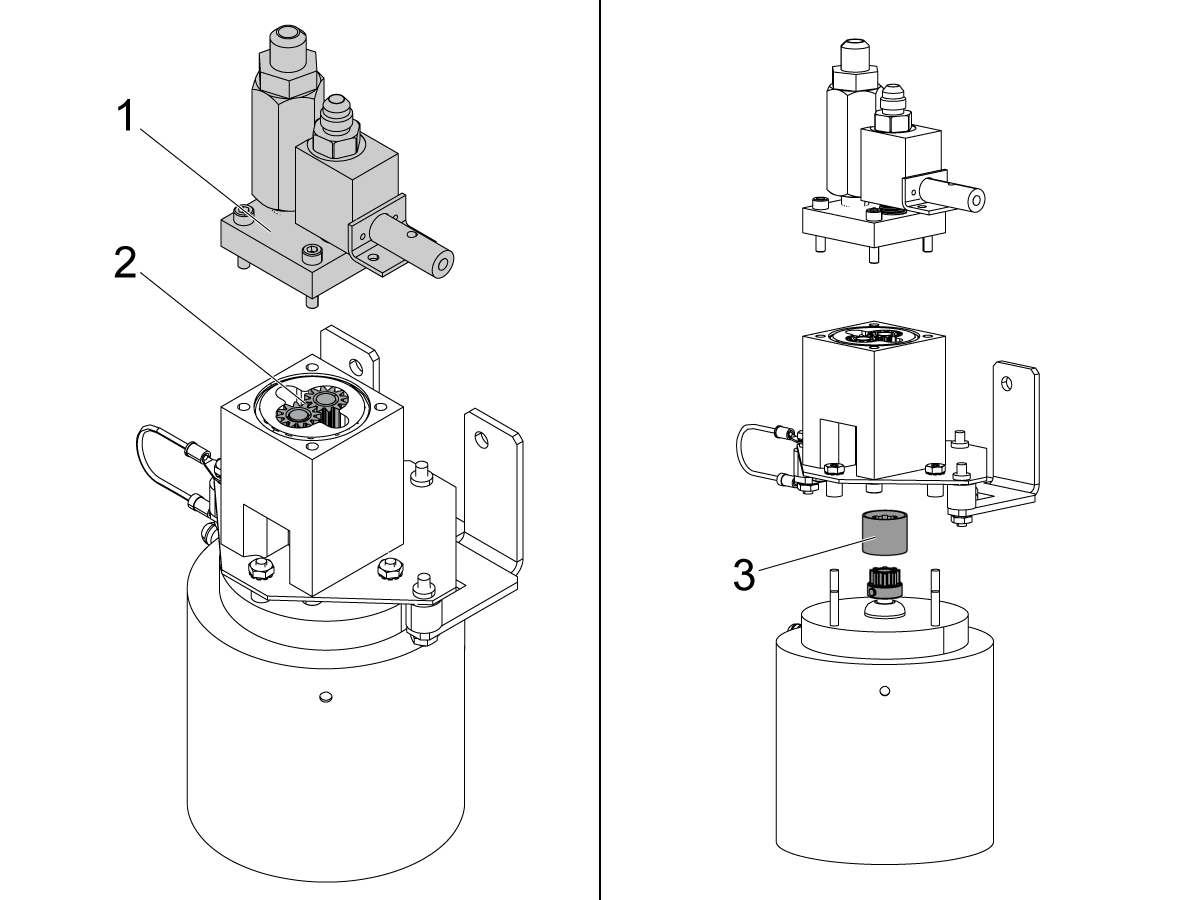
Corrective Action: Inspect the gears or coupler.

Remove the top assembly [1] of the oil pump. Inspect the gears [2]. Make sure they are in good condition. Inspect the sleeved coupler [3]. Replace the sleeved coupler (P/N 93-30-5725) if it is broken.

Low Ambient Shop Temperature

Corrective Action:

Warm up the machine by running the spindle at high speed for 10 minutes to warm up the gearbox housing and the oil.

Oil Flow Switch

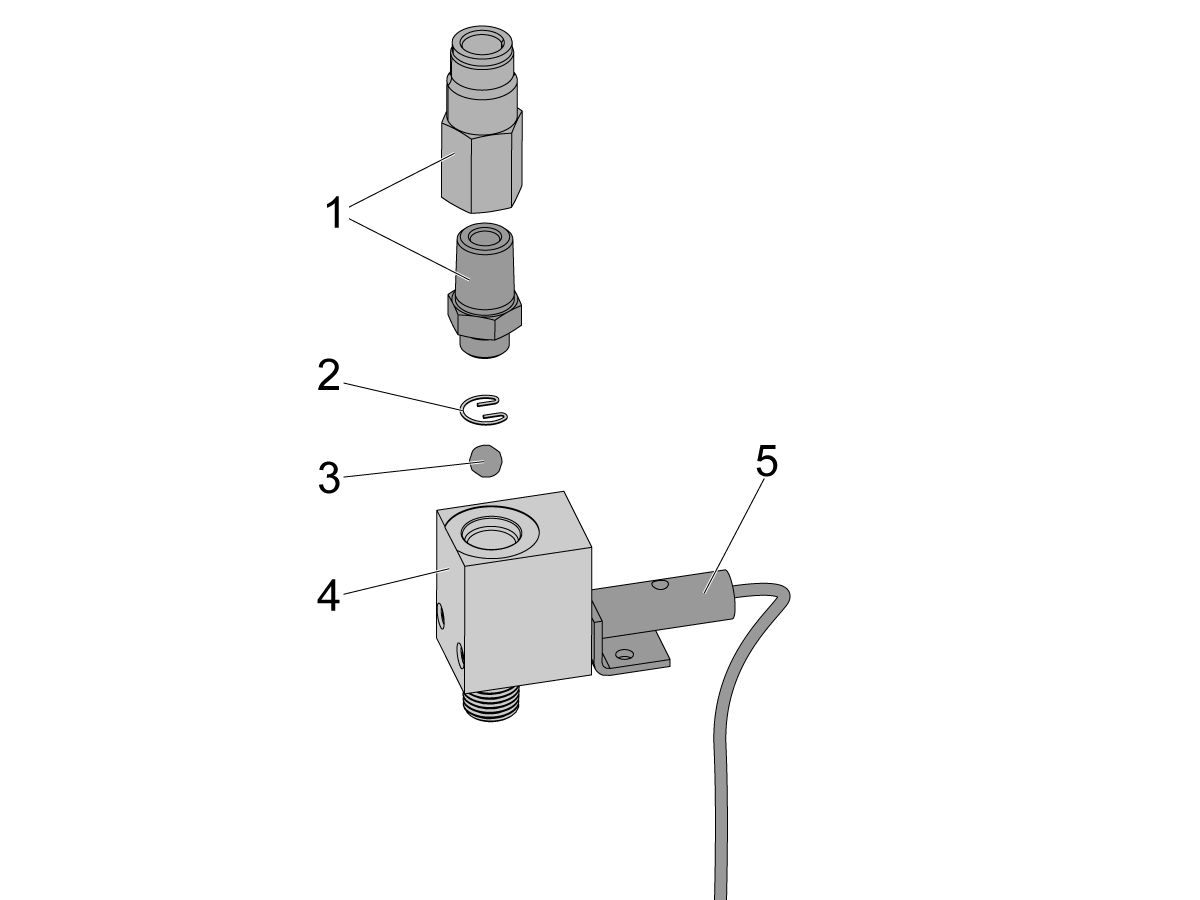
Proximity Senor Oil Flow Switch:
  1. Fittings
  2. Retention clip
  3. Steel ball
  4. Oil flow sensor housing
  5. Proximity sensor

Corrective Action:

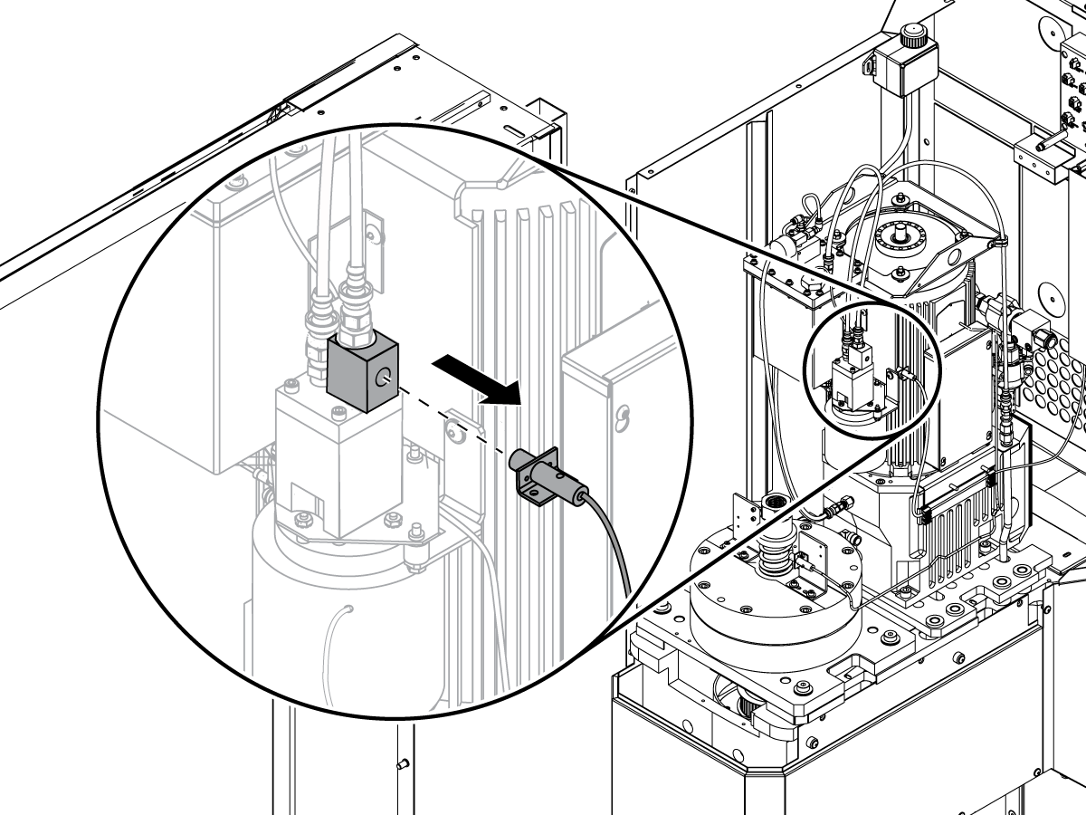
Remove the oil flow sensor from the oil-pump assembly. Use a screw driver to manually operate the switch. Navigate to the I/O tab in DIAGNOSTICS. Make sure the diagnostic bit for Low Lube Press. changes from 0 to 1.

 Note: The name of this diagnostic bit in older software versions is Low GB Oil Flow.

Check Valve Style Oil Flow Sensor:

Corrective Action:

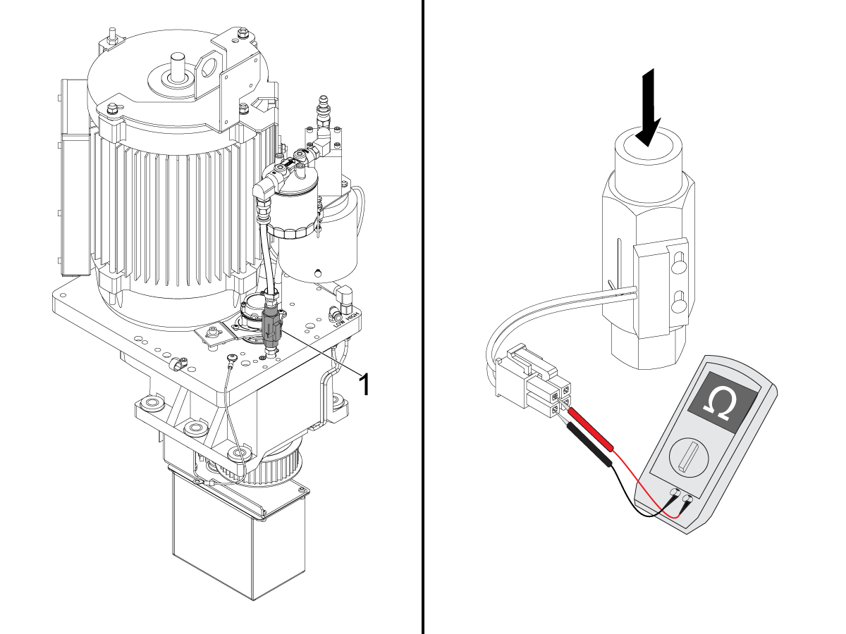
Unplug the oil flow sensor and remove it from the oil-pump assembly. Use a screw driver to manually depress the sensor plunger.  Use a multi meter to monitor continuity across the switch leads.  If continuity is made when the plunger is depressed and broken when the plunger is released the sensor is working properly.

If the sensor is not working properly loosen the two phillips head screws that attach the sensor to the fitting.  Adjust the sensor position until actuating  the plunger reliably makes continuity when the plunger is depressed and breaks continuity when the plunger is released.

Plug the oil flow sensor in and monitor the diagnostic bit for Low Lube Press. as you manually actuate the sensor.

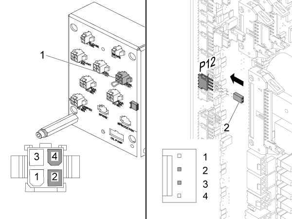
If the diagnostic bit for Low Lube Press. does not change from 0 to 1, disconnect the oil flow sensor from the connector bracket. Put an electrical jumper across the (2) pins in the connector for the oil flow sensor [1]. Make sure the diagnostic bit for Low Lube Press. changes from 0 to 1. If the input changes, the oil flow proximity sensor is faulty.

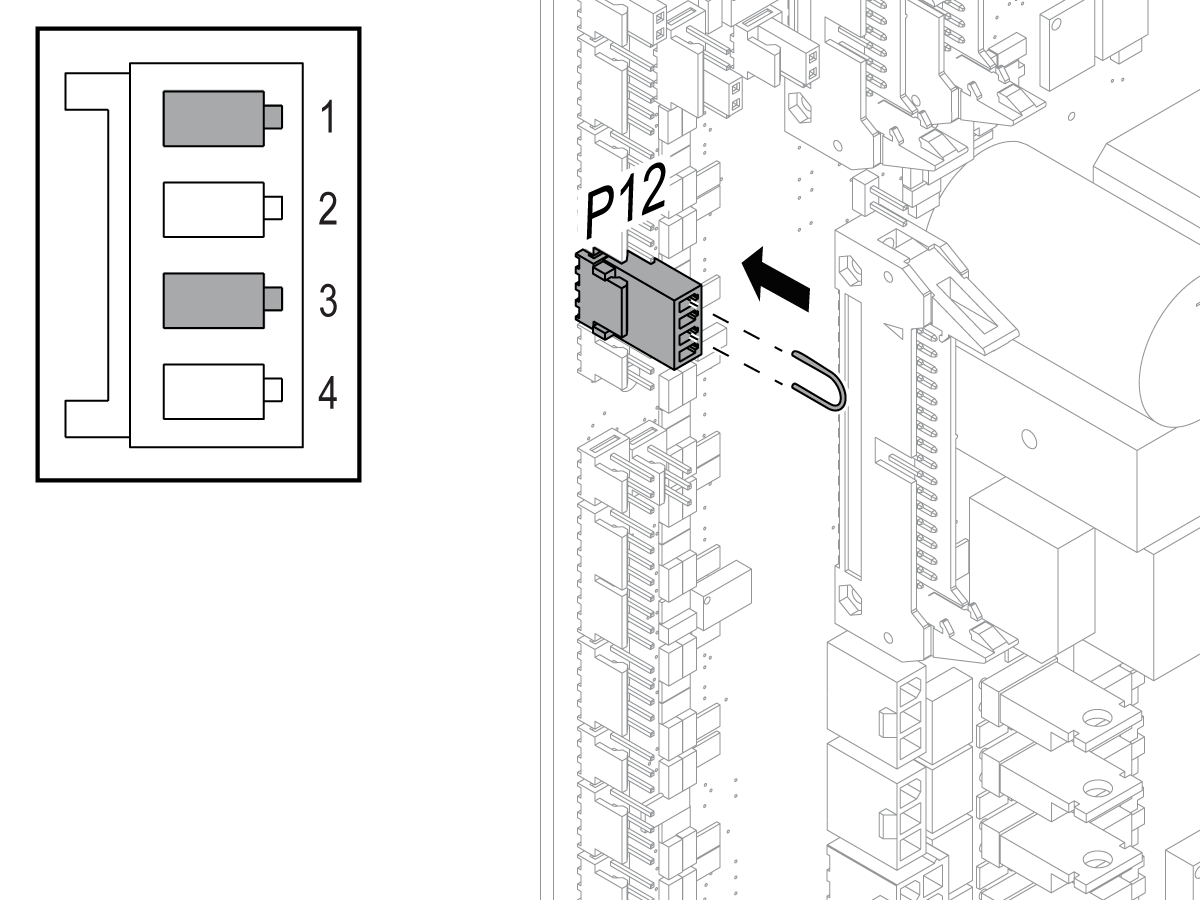
If the diagnostic bit for Low Lube Press. does not change from 0 to 1, disconnect the cable from the P12 connector [2] on the I/O PCB. Put an electrical jumper across pins 2 and 3 of the P12 connector. Make sure the diagnostic bit for Low Lube Press. changes from 0 to 1. If the input changes, the 950 cable is defective. If the input does not change, troubleshoot the I/O PCB.

Oil Pressure Switch

Corrective Action:

Make sure the pressure switch connection is clean and well seated.

Use a voltmeter to check the continuity of the pressure switch when the pump is running. If the switch is open (O.L.) when there is pressure in the system, replace it.

Check the pressure switch with a voltmeter when the pump is running. If the switch is open (O.L.) when there is pressure in the system, replace it.

Oil Level Switch

Corrective Action:

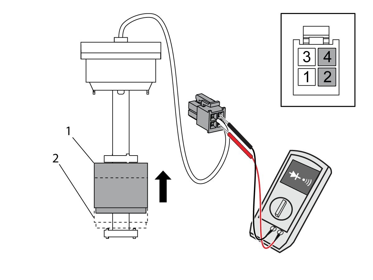
Remove the oil-level switch from the gearbox. While you move the float from position [2] to position [1], measure for continuity across pins 2 and 4 of the connector for the oil-level switch.The oil-level switch operates correctly when:

  • There is not continuity when the magnet is at position [2].
  • There is continuity when the magnet is at position [1].

Replace the oil-level switch if it does not operate correctly.

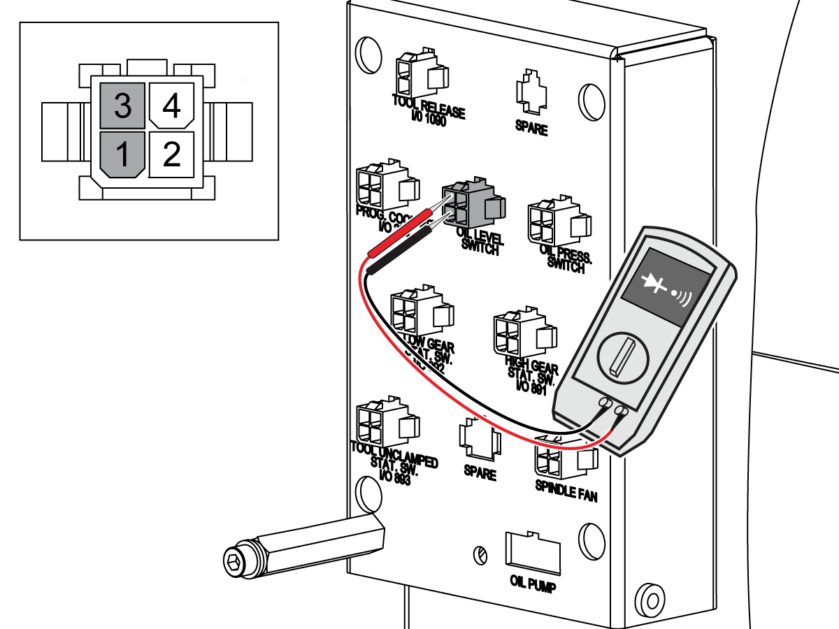
Disconnect the 950 cable from the P12 connector on the I/O PCB. Measure for continuity across pins 1 and 3 of the connector for the oil-level switch on the 950 cable. If there is continuity, there is a short circuit in the 950 cable. Replace the cable.

Put an electrical jumper across pins 1 and 3 of the P12 connector. Press [PARAM/DGNOS] twice. Navigate to the I/O tab. Make sure the diagnostic bit for Low GB Oil Level changes from 1 to 0. If the input does not change, troubleshoot the I/O PCB.

Oil Filter

Corrective Action:

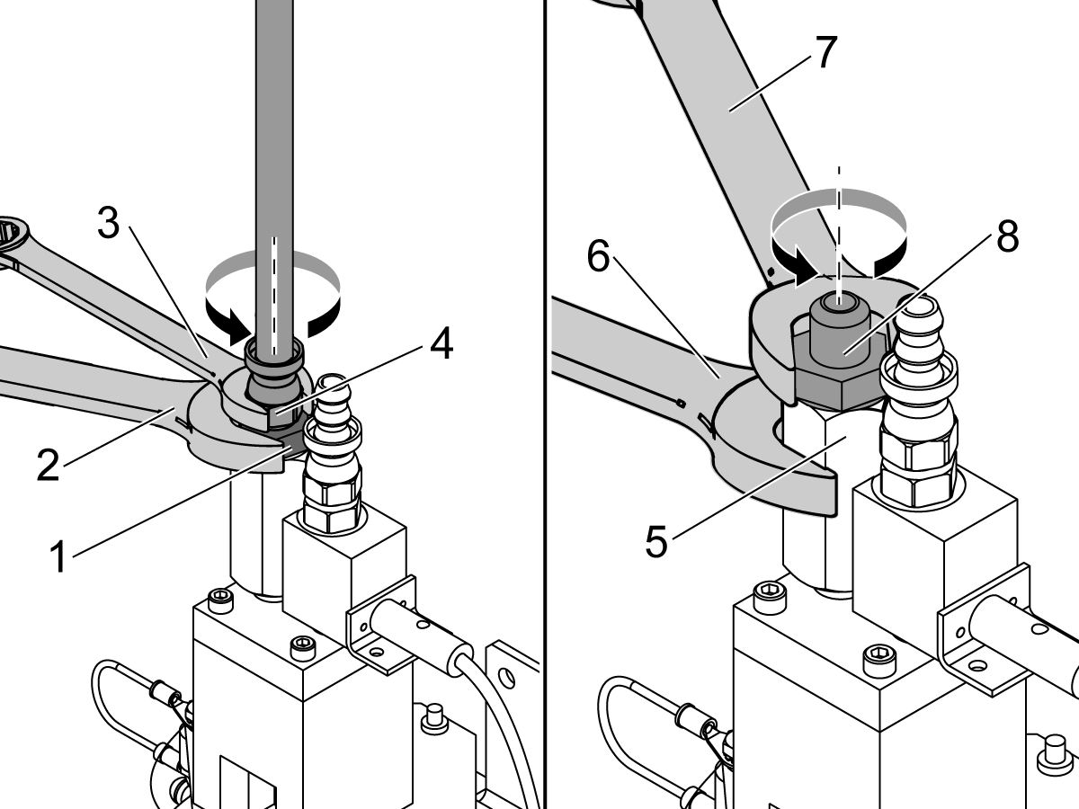
Put a wrench [2] on the straight male-fitting [1] to make sure it does not move. With another wrench [3], turn the hose and the barbed fitting [4] counterclockwise to remove them.

Put a wrench [6] on the inlet-screen housing [5] to make sure it does not move. With another wrench [7], turn the straight male-fitting [8] counterclockwise to remove it.

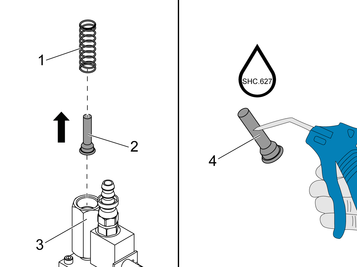
Remove the spring [1] and the inlet screen [2] from the inlet-screen housing [3]. Clean the inlet screen [4]. Reinstall the inlet screen.

Oil-Pump Motor

Corrective Action: Troubleshoot the oil-pump motor.

Command the spindle to operate.

 Note: There is a voltage output to the gearbox oil pump when the spindle operates.

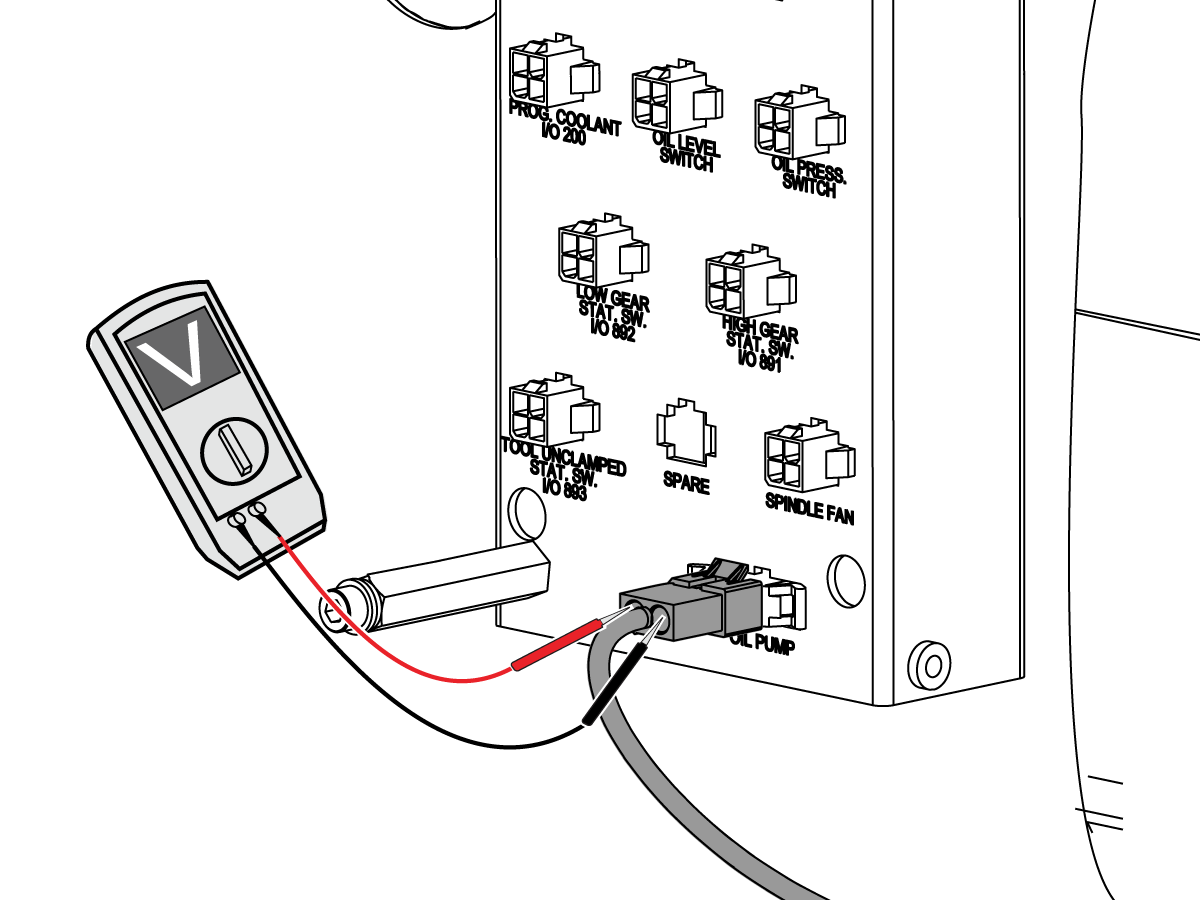
Monitor the motor fan on the gearbox oil pump. If the motor fan on the gearbox oil pump does not operate, make sure the oil pump receives the correct voltage. Use a multimeter with needle-tip probes to measure the voltage across the cable connector for the gearbox oil pump.

 Note: Do not measure the voltage with the oil pump cable disconnected from the 300A cable.

The measured voltage must be 120 VAC. If the voltage is correct and the pump does not operate, go to Section 6.

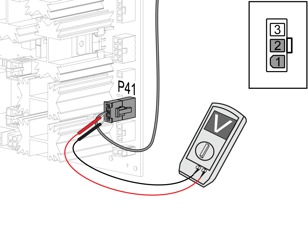
If the voltage is not correct, make sure the voltage output from the I/O PCB is correct. Use a multimeter with needle tip test probes to measure the voltage between pin 1 and pin 2 on the 300A-cable connector at P41 (Classic Haas Control) or P32 (Next Generation Control) on the I/O PCB.

 Note: Do not measure the voltage with the 300A cable disconnected from the P41 connector on the I/O PCB.

The measured voltage must be 120 VAC. If the measured voltage is correct, the 300A cable is defective. If there is no voltage output, refer to these troubleshooting guides:

  • NGC - I/O PCB - Troubleshooting Guide

Sump Tank Missing Weep Hole

Cause:

Sump tank missing weep hole and a change to foam gasket. 

Corrective Action:

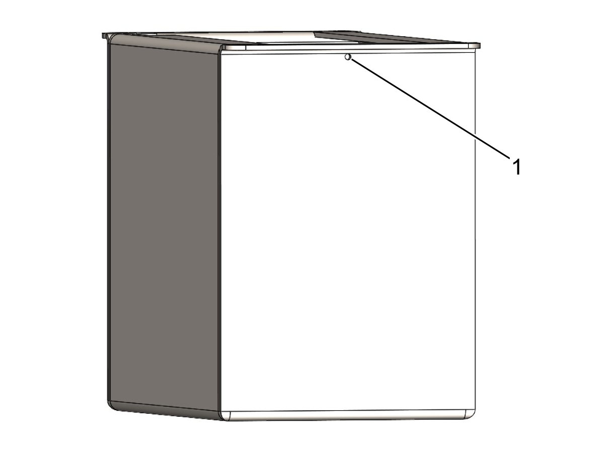
Drill the weep hole on the backside (encoder side) of the sump tank.

1. ø.094 THRU ONE WALL 0.20” From Top Of The Tank.

Clean thoroughly after drilling to not introduce debris.

Note: Do not drill a hole on the front side (spindle side) as coolant can enter the sump.

Wye/Delta Contactor

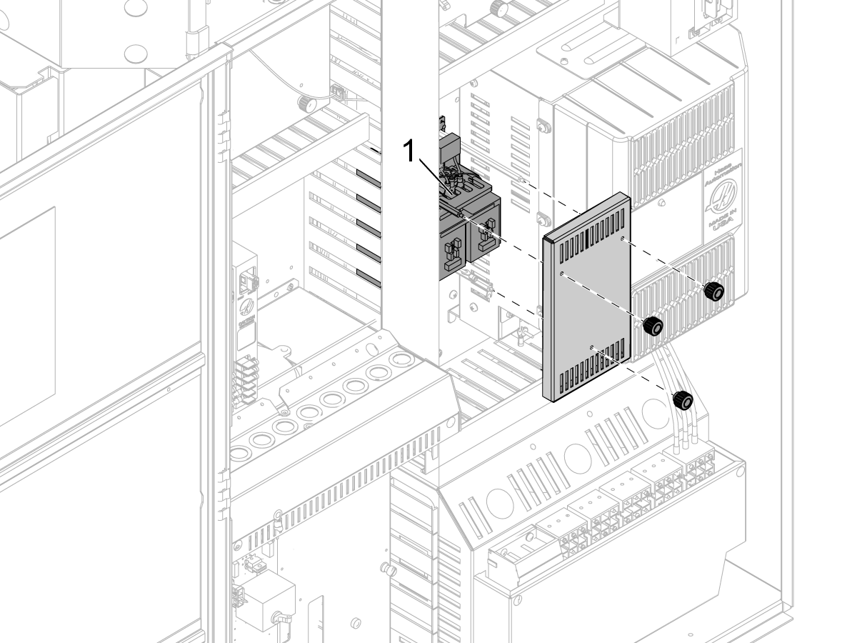
A worn contactor can send unreliable power to the gearbox motor, which can cause a high load. Check the connections at the Wye/Delta contactor. Make sure the terminals are tight.

Corrective Action:

Refer to Wye-Delta Contactor - Troubleshooting Guide to troubleshoot the Wye/Delta connectors.

Excessive Gearbox Noise

Corrective Action:

Determine if the problem is mechanical or electrical by commanding the spindle rpm where the noise is heard and then turning off the power.

If the noise goes away this means that the cause of the noise may be the encoder feedback.   

Damaged gears in the gearbox can cause excessive noise. Contact your local HFO for a vibration analysis to see if the gears are damaged.

Gearbox

Corrective Action:

Manually actuate the High/Low gear solenoid and slowly turn the spindle by hand. The gearbox should shift and the Hi Gear and Low Gear bits on the diagnostic page should change state.

If the gearbox does not shift, it may have internal damage.

If the gearbox shifts, refer to these troubleshooting guides for the high and low gear solenoids and the I/O PCB.

  • Solenoid - Troubleshooting Guide
  • NGC - I/O PCB - Troubleshooting Guide

Introduction

This procedure tells you how to change the oil in the 40T gearbox.

Caution: Make sure that EMERGENCY STOP is ON when you work inside the machine.

Tools Required

  • Mobil SHC - 627

40T - Gearbox - Oil Change

Remove the spindle head covers to gain access to the transmission.

Disconnect the oil return line on the top of the gearbox [3].

Put the oil return line in the container to collect the oil.

Run the spindle at 5 RPM until the oil pump pumps all the oil out of the gearbox into the container.

Note: The control will generate the alarm 2012 INSUFFICIENT SPINDLE GEAR BOX OIL FLOW or 179 LOW GEARBOX OIL PRESSURE. Reset the alarm and keep running the spindle until gearbox is empty.

Once gearbox is empty, stop the spindle and reconnect the oil return line.

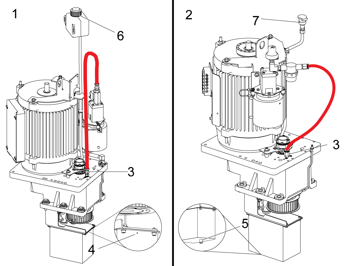
Remove the access cover on the bottom of the spindle head to gain visual access to the oil sump tank and locate the overflow hole. Gearbox built after 02/2015 have the overflow hole on the back of the oil sump tank [4]. Gearbox built before 02/2015 have an overflow hole on the bottom of the oil sump tank [5].

There is either the 500ml reservoir [6] or the fill tube [7] on top of the gearbox. Fill the gearbox with Mobil SHC627 in 4 oz increments until oil starts to come out of the overflow hole on the oil sump tank.

FIND DISTRIBUTOR
Feedback
Haas Logo

美元价格不包括关税、报关费用、保险费、增值税及运费。
USD prices DO NOT include customs duty, customs fees, insurance, VAT, or freight.

人民币价格包含关税、报关费用、货运保险和增值税, 但不包括运费。
CNY prices include customs duty, customs fees, insurance, and VAT. DOES NOT include freight.

Haas Delivered Price

This price includes shipping cost, export and import duties, insurance, and any other expenses incurred during shipping to a location in France agreed with you as a buyer. No other mandatory costs can be added to the delivery of a Haas CNC Product.

KEEP UP WITH THE LATEST HAAS TIPS AND TECHNOLOGY...

Sign up now!   

HAAS TOOLING ACCEPTS THE FOLLOWING:

  • Service & Support
  • Owners
  • Request Service
  • Operator Manuals
  • Haas Parts
  • Rotary Repair Request
  • Pre-Install Guides
  • Shopping Tools
  • Build & Price a New Haas
  • Available Inventory
  • The Haas Price List
  • CNCA Financing
  • About Haas
  • Careers
  • Certifications & Safety
  • Contact Us
  • History
  • Terms & Conditions
  • Haas Tooling Terms & Conditions
  • Privacy
  • Warranty
  • Haas Community
  • Haas Certification Program
  • Haas Motorsports
  • Gene Haas Foundation
  • Haas Technical Education Community
  • Events
  • Join the Conversation
  • Facebook
  • Twitter
  • Flickr
  • YouTube
  • LinkedIn
  • Instagram
  • TikTok
© 2022 Haas Automation, Inc – CNC Machine Tools

2800 Sturgis Rd., Oxnard, CA 93030 / Toll Free: 800-331-6746
Phone: 805-278-1800 / Fax: 805-278-2255

Cookie Notice

We use cookies to improve your user experience. Our Cookie Notice describes which cookies we use, why we use them, and how you can find more information about them. Please confirm you consent to us using analytics cookies. If you do not consent, you may still use our website with a reduced user experience.

Manage Settings

Cookie Notice

We use cookies to improve your user experience. Our Cookie Notice describes which cookies we use, why we use them, and how you can find more information about them. Please confirm you consent to us using analytics cookies. If you do not consent, you may still use our website with a reduced user experience.

Functional Cookies

Analytics Cookies