My Haas Welcome,
!
Haas Tooling MyHaas/HaasConnect Sign In Register Haas Tooling MyHaas/HaasConnect Sign Out Welcome, My Machines Latest Activity My Quotes My Account My Users Sign Out
Find Your Distributor
  1. Select Language
    1. English
    2. Deutsch
    3. Español - ES
    4. Español - MX
    5. Français
    6. Italiano
    7. Português
    8. Český
    9. Dansk
    10. Nederlands
    11. Magyar
    12. Polski
    13. Svenska
    14. Türkçe
    15. 中文
    16. Suomi
    17. Norsk
    18. الإنجليزية
    19. български
    20. Hrvatski
    21. Ελληνικά
    22. Română
    23. Slovenský
    24. Slovenščina
    25. 한국어
    26. 日本語
    27. Українська
  • machines Main Menu
    • Vertical Mills
      Vertical Mills
      Vertical Mills View All
      • Vertical Mills
      • VF Series
      • Universal Machines
      • VR Series
      • VP-5 Prismatic
      • Pallet-Changing VMCs
      • Mini Mills
      • Mold Machines
      • High-Speed Drill Centers
      • Drill/Tap/ Mill Series
      • Toolroom Mills
      • Pocket Mill
      • Compact Mills
      • Gantry Series
      • SR Sheet Routers
      • Extra-Large VMC
      • Double-Column Mills
      • 3+2 Positioning Machines
    • Multi-Axis Solutions
      Multi-Axis Solutions
      Multi-Axis Solutions View All
      • Multi-Axis Solutions
      • Y-Axis Lathes
      • 5-Axis Mills
    • Lathes
      Lathes
      Lathes View All
      • Lathes
      • ST Series
      • Dual-Spindle
      • Box Way Series
      • Toolroom Lathes
      • Chucker Lathe
      • Pocket Lathe
      • Haas Bar Feeders
    • Horizontal Mills
      Horizontal Mills
      Horizontal Mills View All
      • Horizontal Mills
      • 50-Taper
      • 40-Taper
    • Rotaries & Indexers
      Rotaries & Indexers
      Rotaries & Indexers View All
      • Rotaries & Indexers
      • Rotary Tables
      • Indexers
      • 5-Axis Rotaries
      • Extra-Large Rotaries
    • Special Series
      Special Series
      Special Series View All
      • Special Series
      • EU_Series_Redirect
    • Automation Systems
      Automation Systems
      Automation Systems View All
      • Automation Systems
      • Mill Automation
      • Lathe Automation
      • Automatic Parts Loaders
      • Automation Models
    • Desktop Machines
      Desktop Machines
      Desktop Machines View All
      • Desktop Machines
      • Desktop Mill
      • Desktop Lathe
      • Control Simulator, Standard
      • Control Simulator, Premium
    • Shop Equipment
      Shop Equipment
      Shop Equipment View All
      • Shop Equipment
      • Knee Mill
      • Haas Manual Lathes
      • Haas Saws
    • Fabrication Machines
      Fabrication Machines
      Fabrication Machines View All
      • Fabrication Machines
      • Laser Cutting Machines
      • CNC Press Brakes
    • QUICK LINKS Special Series  Special Series 
      EU SERIES EU SERIES BUILD & PRICE | PRICE LIST BUILD & PRICE | PRICE LIST In-Stock Machines In-Stock Machines WHAT’S NEW WHAT’S NEW YOUR FIRST CNC YOUR FIRST CNC
      SHOPPING TOOLS
      • Build & Price a Haas
      • Price List
      • Available Inventory
      • CNCA Financing
      WANT TO TALK TO SOMEONE?

      A Haas Factory Outlet (HFO) can answer your questions, and walk you through your best options.

      CONTACT YOUR DISTRIBUTOR >
  • Options Main Menu
    • The Haas Control Value Option Packages
      Value Option Packages
      Value Option Packages View All
      • Value Option Packages
    • Product Image Spindles
      Spindles
      Spindles View All
      • Spindles
    • Product Image Tool Changers
      Tool Changers
      Tool Changers View All
      • Tool Changers
    • Product Image 4th- | 5th-Axis
      4th- | 5th-Axis
      4th- | 5th-Axis View All
      • 4th- | 5th-Axis
    • Product Image Turrets & Live Tooling
      Turrets & Live Tooling
      Turrets & Live Tooling View All
      • Turrets & Live Tooling
    • Product Image Probing
      Probing
      Probing View All
      • Probing
    • Haas Chip & Coolant Management Chip & Coolant Management
      Chip & Coolant Management
      Chip & Coolant Management View All
      • Chip & Coolant Management
    • The Haas Control The Haas Control
      The Haas Control
      The Haas Control View All
      • The Haas Control
    • Product Image Product Options
      Product Options
      Product Options View All
      • Product Options
    • Product Image Tooling & Fixturing
      Tooling & Fixturing
      Tooling & Fixturing View All
      • Tooling & Fixturing
    • Product Image Workholding
      Workholding
      Workholding View All
      • Workholding
    • Product Image 5-Axis Solutions
      5-Axis Solutions
      5-Axis Solutions View All
      • 5-Axis Solutions
      • 5 Easy Steps to 5-Axis
    • QUICK LINKS Special Series  Special Series 
      EU SERIES EU SERIES BUILD & PRICE | PRICE LIST BUILD & PRICE | PRICE LIST In-Stock Machines In-Stock Machines WHAT’S NEW WHAT’S NEW YOUR FIRST CNC YOUR FIRST CNC
      SHOPPING TOOLS
      • Build & Price a Haas
      • Price List
      • Available Inventory
      • CNCA Financing
      WANT TO TALK TO SOMEONE?

      A Haas Factory Outlet (HFO) can answer your questions, and walk you through your best options.

      CONTACT YOUR DISTRIBUTOR >
  • Why Haas Main Menu
      Discover the Haas Difference
    • Why Haas
    • MyHaas
    • Education Community
    • Industry 4.0
    • Haas Certification
    • Customer Testimonials
  • Service Main Menu
      Welcome to Haas Service
      SERVICE HOME Operator’s Manuals How-To Procedures Troubleshooting Guides Preventive Maintenance Haas Parts Haas Tooling Videos
  • Videos Main Menu
  • Main Menu
    • View All
    • View All
    • View All
    • View All
      • HTEC Curriculum Support
      • Haas Value Option Packages (VOP) Journey
    • View All
      • Haas 10 kg Cobot Package
      • Cobot Kits
      • DC-1 Drill Center
      • CNC Sales News
      • Do More With Your Haas
    • View All
    • View All
      • contact-us-test
      • 4 - AUTOMATION SYSTEMS
      • Carousel-V2
      • expert test
      • Demo_Day_Trident-test
      • Link Test
      • image-sale-tag-test
      • article-list-test
      • Haas 25 kg Robot Package
      • test-algolia-page
    • View All
    • View All
    • View All
    • View All
      • calc-test
    • View All
    • QUICK LINKS Special Series  Special Series 
      EU SERIES EU SERIES BUILD & PRICE | PRICE LIST BUILD & PRICE | PRICE LIST In-Stock Machines In-Stock Machines WHAT’S NEW WHAT’S NEW YOUR FIRST CNC YOUR FIRST CNC
      SHOPPING TOOLS
      • Build & Price a Haas
      • Price List
      • Available Inventory
      • CNCA Financing
      WANT TO TALK TO SOMEONE?

      A Haas Factory Outlet (HFO) can answer your questions, and walk you through your best options.

      CONTACT YOUR DISTRIBUTOR >
  • Haas Tooling Main Menu
  • Haas Service Parts Main Menu

My Haas Welcome,
!
Haas Tooling MyHaas/HaasConnect Sign In Register Haas Tooling MyHaas/HaasConnect Sign Out Welcome, My Machines Latest Activity My Quotes My Account My Users Sign Out
Find Your Distributor
  1. Select Language
    1. English
    2. Deutsch
    3. Español - ES
    4. Español - MX
    5. Français
    6. Italiano
    7. Português
    8. Český
    9. Dansk
    10. Nederlands
    11. Magyar
    12. Polski
    13. Svenska
    14. Türkçe
    15. 中文
    16. Suomi
    17. Norsk
    18. الإنجليزية
    19. български
    20. Hrvatski
    21. Ελληνικά
    22. Română
    23. Slovenský
    24. Slovenščina
    25. 한국어
    26. 日本語
    27. Українська
×

Search Results

Web Pages

Images

    • <
    • 1
    • >

15" LCD Monitor / SKBIF - Troubleshooting Guide - NGC - TG0006

Service Home 15" LCD Monitor / SKBIF - Troubleshooting Guide - NGC - TG0006

15" LCD Monitor / SKBIF - Troubleshooting Guide - NGC - TG0006

Jump to Section Back to Top

19.3 - 15" LCD Monitor / SKBIF - Troubleshooting Guide

Recently Updated Last updated: 10/08/2025

15" LCD Monitor / SKBIF - Troubleshooting Guide - NGC


TG0006

Introduction

SKBIF Inspection Report Checklist

Download and fillout the SKBIF Inspection Report Checklist below before replacing any parts.

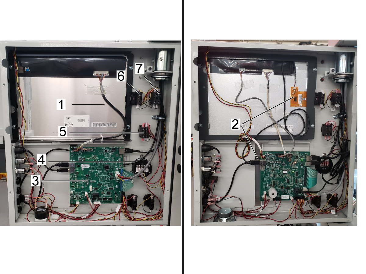
[1] 15" LCD.

[2] 15" Touchscreen LCD.
NOTE: Not all machines are equipped with the LCD touchscreen.  The LCD touch screen has a USB cable that plugs into the SKBIF PCB.  

[3] SKBIF PCB

[4] Handle Jog

[5] E-Stop Button

[6] Power Off

[7] Power On

Symptom Table

Symptom Possible Cause Corrective Action
Alarm 825 USER INTERFACE COMMUNICATION FAULT There is a problem with the communication cable from Main PCB to SKBIF PCB. The communication between the Main PCB and SKBIF PCB is lost or no signal. Check the RJ45 cable connected to SKBIF at J28 to Main PCB J9, make sure the cable is not damaged or it has a loose connection. To test the cable refer to Network Cable Tester Tool procedure.
Machines with SKBIF Version 6.xx.  Alarm 546 SERIAL KEYBOARD COMMUNICATION FAULT. The SKBIF firmware is outdated. Make sure you have SKBIF firmware version 6.6 or higher.  Refer to SKBIF PCB / RJH Firmware Update - NGC procedure.
The LCD turns to a black screen. Alarm 967 SKBIF COMMUNICATION FAULT. There is a problem with the communication cable from Main PCB to SKBIF PCB. See SKBIF Troubleshooting section below.
The supply voltage from PSUP PCB to SKBIF PCB is not correct.
The backlight and LCD data cables are not connected correctly.
The wires to the [POWER ON], [POWER OFF], [EMERGENCY STOP], [FEED HOLD] and [CYCLE START] contactors terminals are loose.
The beacon light does not turn on. The beacon light cable is not connected. Make sure the beacon light is connected to SKBIF at P10.
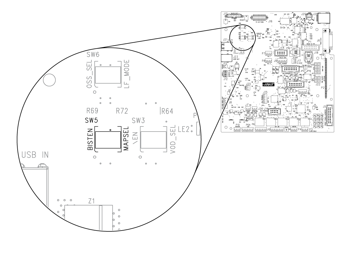
The control has a blurry screen.

A switch on the SKBIF is not correctly set.

Change the MAPSEL switch to the opposite position. See the section below.
The screen flickers during spindle deceleration (running spindle then pressing "Reset" key) or during heavy cuts. The cable from the Maincon PCB connected J9 to the SKBIF at J28 is defective.
  1. Check the RJ-45 cable connection from Maincon PCB (J9) to SKBIF PCB (J28). To test the cable refer to Network Cable Tester Tool procedure.
  2. Inspect the RJ-45 connector housing on the Maincon PCB & SKBIF PCB for bent pins.
The RJ-45 connector housing is damaged on the SKBIF or Maincon PCB. Make sure the RJ-45 connector housing is solder to the PCB and not loose.
You get a blank screen with continuous beeping at power on. The jog handle or wiring is defective.
  1. Power off the machine.
  2. Check the wiring to the jog handle, make sure all the cables are connected in the correct location.
  3. Set the meter to ohms, measure resistance between front panel ground to the +5Vdc of jog handle - it should not read zero ohms. If shorted, disconnect the +5Vdc wire from the Jog Handle and check if the problem is the jog handle or the SKIBF.
Machines with software version prior to 100.17.000.2034 . The control freezes, blank monitor, black screen, keypad not working, won't boot sometimes, random shutdowns, or software alarms. Caused by a software error. Refer to the: Next Generation Control - Maincon / Software Update Troubleshooting Guide
Alarm 2001 EMERGENCY STOP SWITCH ERROR
There is a loose connection from the E-stop button to the SKBIF PCB.
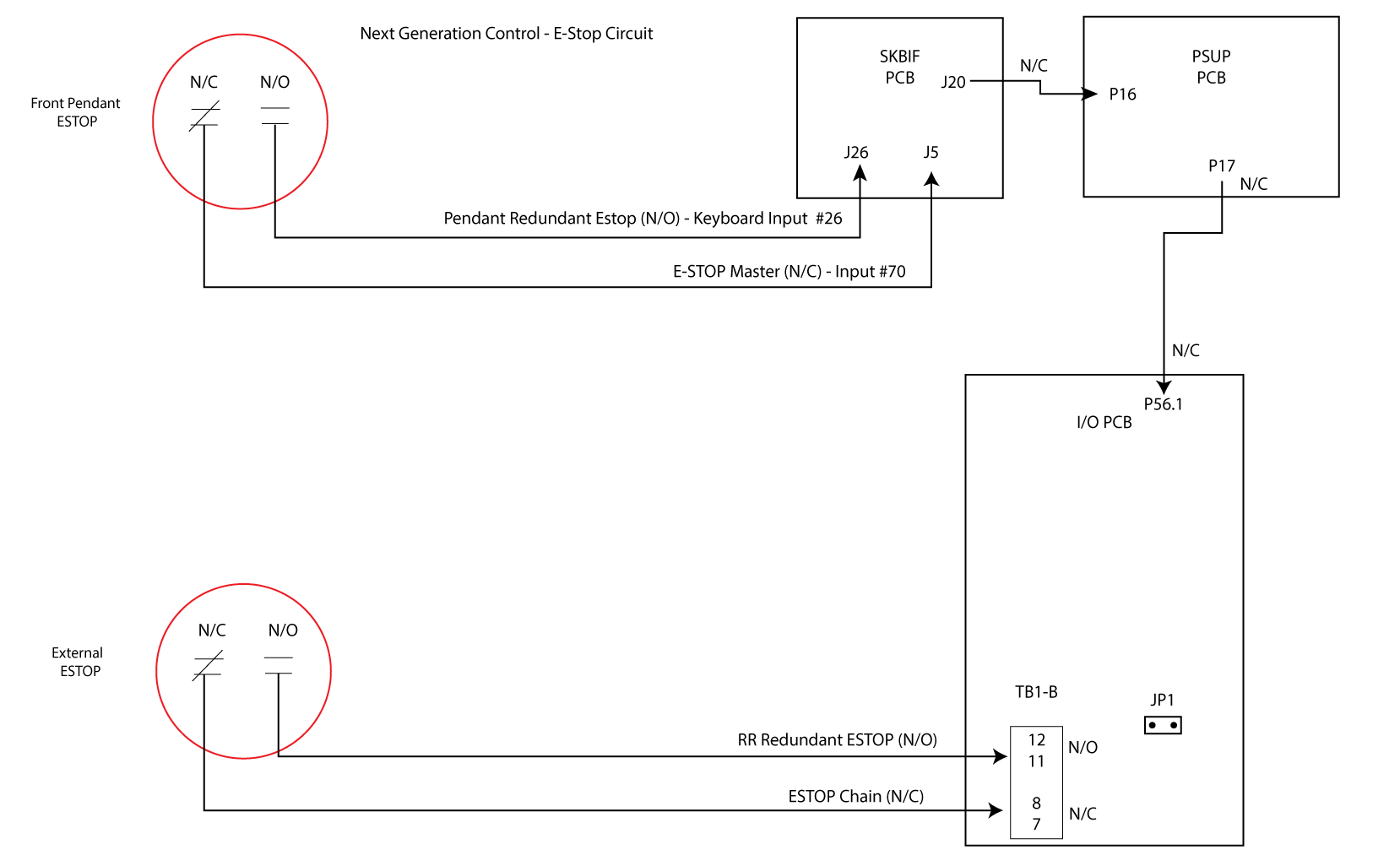
  1. Go to Diagnostic Page --> Keyboard I/O
  2. Type REDUNDANT_ESTOP then press [F1].
  3. With [EMERGENCY STOP] released the INPUT #26 REDUNDANT _ESTOP value should = 1.
  4. Press [EMERGENCY STOP].  The INPUT #26 REDUNDANT _ESTOP value should = 0. If it remained = 1 check the cable plug to SKBIF J26 see diagrams located at the end of this Troubleshooting Guide.

Seized hydraulic union triggered Hydraulic Union Safety Device.

Only applies to these machines built after 12/20/2023:

ST - 10/15/20/25/28/30/35/L/Y/LY 

REBOOT ONLY: ST-40/40Y/45/45Y (note: For ST-45/45L/45Y machines equiped with optional workholding)

Check the Hydraulic Union Safety Device cable attached to the hydraulic union drain hose.

There is a loose connection from the Hydraulic Union Safety Device adaptor to the I/O PCB. 

Only applies to these machines built after 12/20/2023:

ST - 10/15/20/25/28/30/35/L/Y/LY 

REBOOT ONLY: ST-40/40Y/45/45Y (note: For ST-45/45L/45Y machines equiped with optional workholding)

Check the cable connected to the I/O PCB at P12, make sure the cable is not damaged or has a loose connection. Refer to the I/O PCB - Troubleshooting Guide - NGC.
LCD Touchscreen.  Turned setting 381 to On, but the touchscreen does not respond to touch commands. The touchscreen feature is not enabled. To enable the Touchscreen set setting 381 Enable Touchscreen to On.
The configuration files are outdated. As of software version 100.19.000.1400 or higher a parameter 2257 Touchscreen Suport has been added, this parameter must be set to TRUE.  If not you will need to contact the service department to have it enabled.
Too much electrical noise in the system. Add ferrites to two SKBIF USB cables and add a new ground wire connected to the control cabinet. Refer to the SKBIF Reduce Electrical Noise section below for more information. 
The touchscreen continues to function after turning Setting 381 to OFF. The control does not recognize the touchscreen module.

Expected fix will be Software Version 100.23.000.1000.

Unplug the Touchscreen USB cable from the top port at J21 on the SKBIF PCB.

Note: When Software Version 100.23.000.1000 is released. Update the machine software, plug the touchscreen USB cable back into the SKBIF PCB at J21, and turn Setting 381 to OFF.

HSG-N 02-17-2023

LCD Touchscreen
The TouchScreen does not respond to touch commands.
The touchscreen feature is not enabled. To enable the Touchscreen set setting 381 Enable Touchscreen to On.
The touchscreen is not calibrated. Use the touchscreen configuration page to calibrate, test, and restore default settings.
The touchscreen configuration is located in the maintenance section.
Press [DIAGNOSTIC] to go to the Maintenance and navigate to the Touchscreen tab. 
Follow the instructions on the screen.  After calibration you need to cycle power.
The touchscreen USB cable is not connected correctly to the SKBIF PCB. Make sure that the USB cable connection is connected to J21 at SKBIF PCB.
Too much electrical noise in the system. Add ferrites to two SKBIF USB cables and add a new ground wire connected to the control cabinet. Refer to the SKBIF Reduce Electrical Noise section below for more information. 

HSG-N 05-11-2023
LCD TouchScreen.
Some tabs look dark as they have been pushed.
This is normal,  this is used to distiguish the family of tabs the current screen is showing.
The sound of the beeper only works when I power on the machine. The beeper volume setting is turned off. Go to setting 356 and set to a value higher than 0.
The beeper volume is low or inaudible. The SKBIF PCB or beeper is defective. Machines with SKBIF (34-4510) PCB the beeper is built into the SKBIF.  This beeper can not be tested,  check for voltage going to the SKBIF, if everything checks out ok then the SKBIF PCB is defective. Note:  Do not replace the speaker,  the speaker does not produce the beeper sound.

Machines with SKBIF  (34-4243G) PCB the beeper is mounted outside and connected to the SKBIF.  This beeper can tested with a 9V battery.
After upgrading to SKBIF Firmware Version 6.8 there is a longer delay between pressing the [Power On] button and seeing something on the LCD display. This is normal behavior. The beacon will blink during this time to indicate the machine is turning on.

PCB serial number

 Note: The PCB's serial number must be included in the inspection report checklist. The serial number is on a sticker [1] on the top of the inspection checklist. 

The serial number will start with two letters, followed by eight digits. Include both the letters and numbers on the inspection report. 

SKBIF Troubleshooting

  1. Remove the LCD back cover.
  2. Check J13 backlight and J16 LCD data connectors. Make sure the connectors are seated, and wires are not broken.
  3. Check the wires going to the [POWER ON], [POWER OFF], [EMERGENCY STOP], [FEED HOLD] and [CYCLE START] 
    contactors. Make sure the connections are tight.
  4. Look at the status LED lights.  Refer to the LED table below.
  5. Set the volt meter to DC. Check for +12Vdc supply voltage at J20 you should measure approximately +12Vdc. If this voltage is lower than +11Vdc or not present make sure J20 connector is properly seated, and trace the voltage back to the LVPS. Refer to the above electrical diagram.
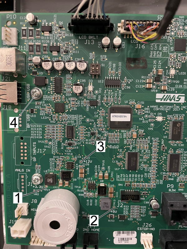
  6. The SKBIF PCB generates +3.3Vdc, +5Vdc. Check these voltages at the following test points.
    • Put the black probe on the screw (ground) [4] and the red probe at TP14 (+3.3Vdc) [1] you should measure approximately +3.3Vdc.
    • Put the black probe on the screw (ground) [4] and the red probe at TP13 (+5Vdc) [2] you should measure approximately +5Vdc.
    • Put the black probe  on the screw (ground) [4] and the red probe at TP12 (+12Vdc) [3] you should measure approximately +12Vdc.


    If these voltages are low or no voltage is measured, disconnect all the connectors from the SKBIF PCB except the J20 connector, and measure again. If after doing this there is still no voltage then the SKBIF PCB is defective.

    If after disconnecting the components, the voltages are correct, then there is a short circuit in one of the components connected to the SKBIF for example, remote jog handle, handle Jog, etc. Determine which component is at fault.

     If everything checks out ok, then the SKBIF PCB is defective.

    NOTE: Do not replace the speaker,  the speaker does not produce the beeper sound.

SKBIF Reduce Electrical Noise

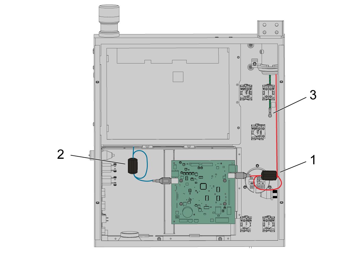
In order to reduce induced electrical noise from the system, complete the following procedure:

1.  Install a ferrite 64-1252 [1] onto the cable connected to SKBIF J9 connection.

2.  Install a ferrite 64-1252 [2] on the touchscreen cable connected to SKBIF J11 connection.

 NOTE: Make sure to loop the USB cable within the ferrite as shown. 

3. Attach the ground wire [3] from pendant to the control cabinet. Use the ground cable table below to order the correct cable.

 NOTE: Recommended to attach the ground wire to the cable clamp as not all screws in that area can be used for grounding. 

Use any available grounding screw on the inside of the control cabinet. 

NOTE: For VS-1 & 3 machines, two ground cables will need to be used due to the long length. 

Lathe Hydraulic Union Safety Device

  1. Push [POWER OFF]. Remove paneling to gain access to the hydraulic union. Check hydraulic union and surrounding parts for damage, replace as needed. If the hydraulic union is damaged, follow the necessary  steps in the ST Spindle Actuator and Adapter Replacement Guide to replace it. 
  2. Check the cable attached to the hydraulic drain hose. Make sure the Hydraulic Union Safety Device noose with the audio jack connector is plugged in. 
  3. Install paneling. Push [POWER ON]. Push [ALARMS]. Push [RESET].
  4. Check to see if EMERGENCY STOP alarm has cleared. If it the EMERGENCY STOP alarm is still present follow steps in the Lathe I/O PCB Hydraulic Union Safety Device Connection sub-procedure of I/O PCB - Troubleshooting Guide - NGC.


Ground Cables

Ground Cable Machines
33-5920 Ground Cable 6 ft CM-1, CL-1 EC-1600/ZT/ZT-5AX, SR-3015P
33-5921 Ground Cable 10 ft EC-400 & -500 (50T),  VC-400/SS, TM-0/P & TM-1/P (REBOOT), EC-630
33-5922 Ground Cable 11.5 ft TL-1/P & 2/P,  ST-10/Y & -15/Y,  DM-1 & 2,  DT-1 & 2,  TM-2/P ( REBOOT)
33-5923 Ground Cable 13 ft VF-1/-1YT/-1SSYT, VF-2/-2SS/-2TR/-2SSYT/-2YT/, VF-3/-3SS/-3SSYT/-3YT/-4/-4SS (2018),  VF-3YT/-5/-5TR-/5XT/ (50T) [2018], VF-5/-5XT/-5TR (40T), VF-5P, MM / MM2 / SMM / SMM2, MM-UK,  VM-2 & -3, GR-510/-712,  ST-20/Y & -25/Y & -28/Y [2018],  DS-30Y (REBOOT)
33-5924 Ground Cable 14 ft ST-10L/LY & 15/L/LY, ST-30/Y & -35/Y (2019), DS-30Y (NON-REBOOT)
33-5925 Ground Cable 16.5 ft VF-6 - 14 (40T & 50T), VF-6SS, VM-6, VR-9 & -11 & -14, ST-20L/-25L-28L, ST-20L/LY & 25L/LY & 28L/LY, UMC-350/HD, UMC-500/SS, UMC-1000P & -1000SS-P, UMC-1500-DUO & UMC-1500SS-DUO
33-5926 Ground Cable 20 ft VF-8 (40T & 50T), VF-9 (50T), VR-8, UMC-750/SS (2018), UMC-1000SS, UMC-1250/SS, ST-30L/LY & ST-35L/LT (2019), ST-40 & -45 (REBOOT), ST-40Y & -45Y
33-5927 Ground Cable 23.50 ft ST-40, GM-2/-5AX, HDC-3-5AX
33-5928 Ground Cable 30 ft ST-40L & 50
33-5930 Ground Cable 30 ft VS-1 & 3 (Control cabinet end)
33-5931 Ground Cable 14.5 ft VS-1 & 3 (Pendant end)

LED Table

The following table applies to -4510X SKIBF PCB.

LED# Status Corrective Action
LE1 (PASS/EQ, Lock) Amber This is normal condition. The SKBIF and Main PCB are communicating.
LE3 Sync Green
LE1 (PASS/EQ, Lock) Red The communication between the Main PCB and SKBIF PCB is lost or no signal. Check the RJ45 cable connected to SKBIF at J28 to Main PCB J9, make sure the cable is not damaged or it has a loose connection. To test the cable refer to Network Cable Tester Tool procedure.
LE3 Sync OFF

The following table applies to -4243X and -4241X SKIBF PCB.

LED# Status Corrective Action
LE1 SYNC OFF This is normal condition. The SKBIF and Main PCB are communicating.
LE2 (PASS/EQ, Lock)  AMBER
LE1 SYNC GREEN The communication between the Main PCB and SKBIF PCB is lost or no signal. Check the RJ45 cable connected to SKBIF at J28 to Main PCB J9, make sure the cable is not damaged or it has a loose connection. To test the cable refer to Network Cable Tester Tool procedure.
LE2 (PASS/EQ, Lock) RED

Blurry Screen - Dip Switches

Corrective Action: Locate the MAPSEL / S1 dip switch on the SKBIF PCB. Switch the dipswitch to the opposite position.

PCB Component Inspection

Intermittent symptoms or alarms can be caused by component failure. Below is a list of possible failures:

  1. Missing solder on all or some components pins
  2. Poor solder
  3. Solder bridges
  4. Wrong component installation (orientation)
  5. Missing components

     Note: Some PCB's have unused circuits and are missing components intentionally, look for broken off components.

  6. Broken components
  7. Broken pins on IC's
  8. Bent pins on the connectors

Use a magnifying glass to inspect the circuit components on the front and back of the SKBIF PCB. Below are the circuit component zones to inspect:

  1. Inputs connectors (Keyboard, E-stop, Power On/OFF etc.)
  2. RJ-45 connector (SKBIF PCB communication with Maincon PCB, LCD Data)
  3. LCD circuit components (LCD Backlight, LCD Data).
  4. Inspect all solder joints for missing solder.

 Important: If you find a damaged component, replace the SKIBF PCB, inspect the new SKBIF PCB circuit components before installing.

Electrical Diagrams

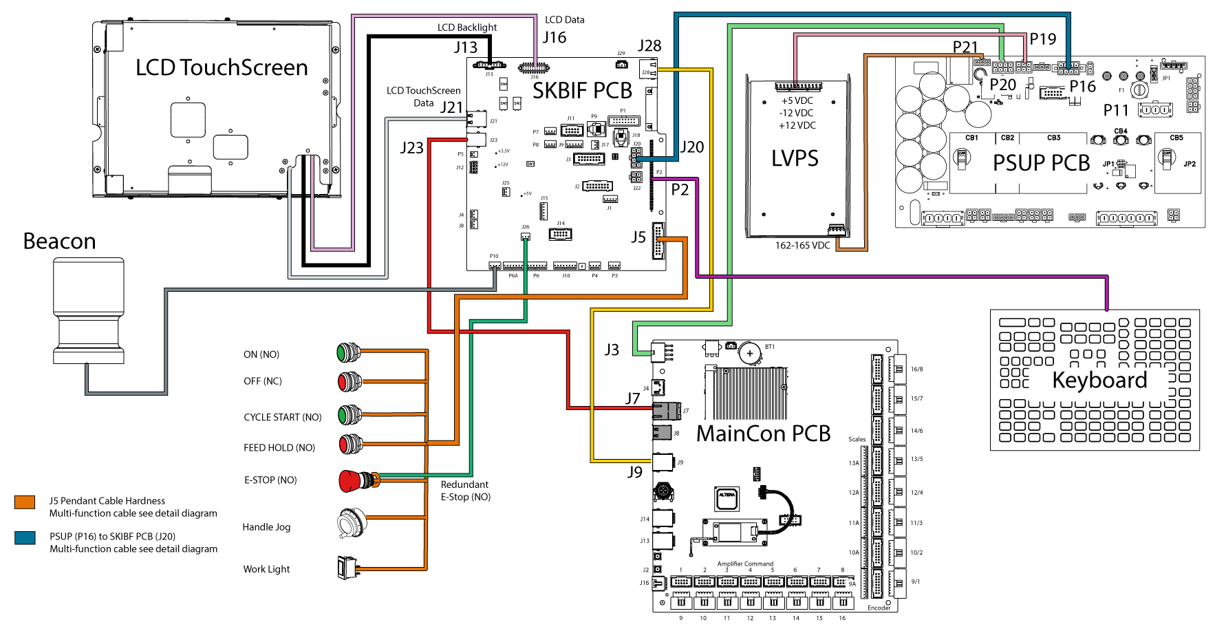
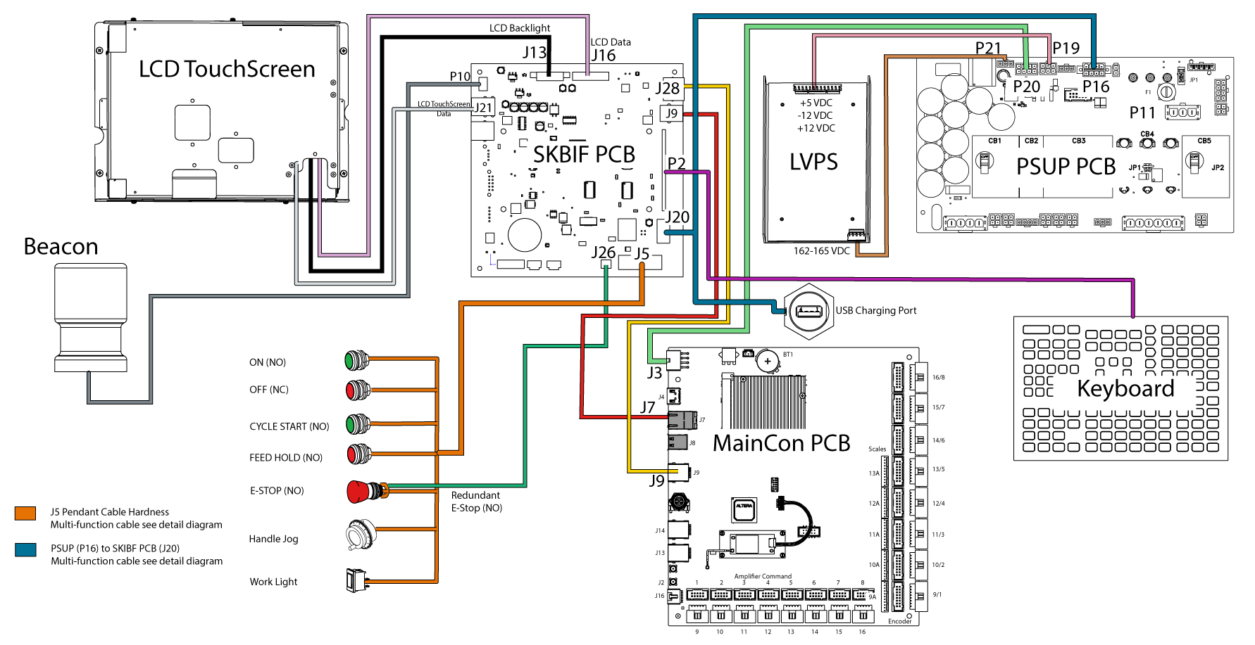
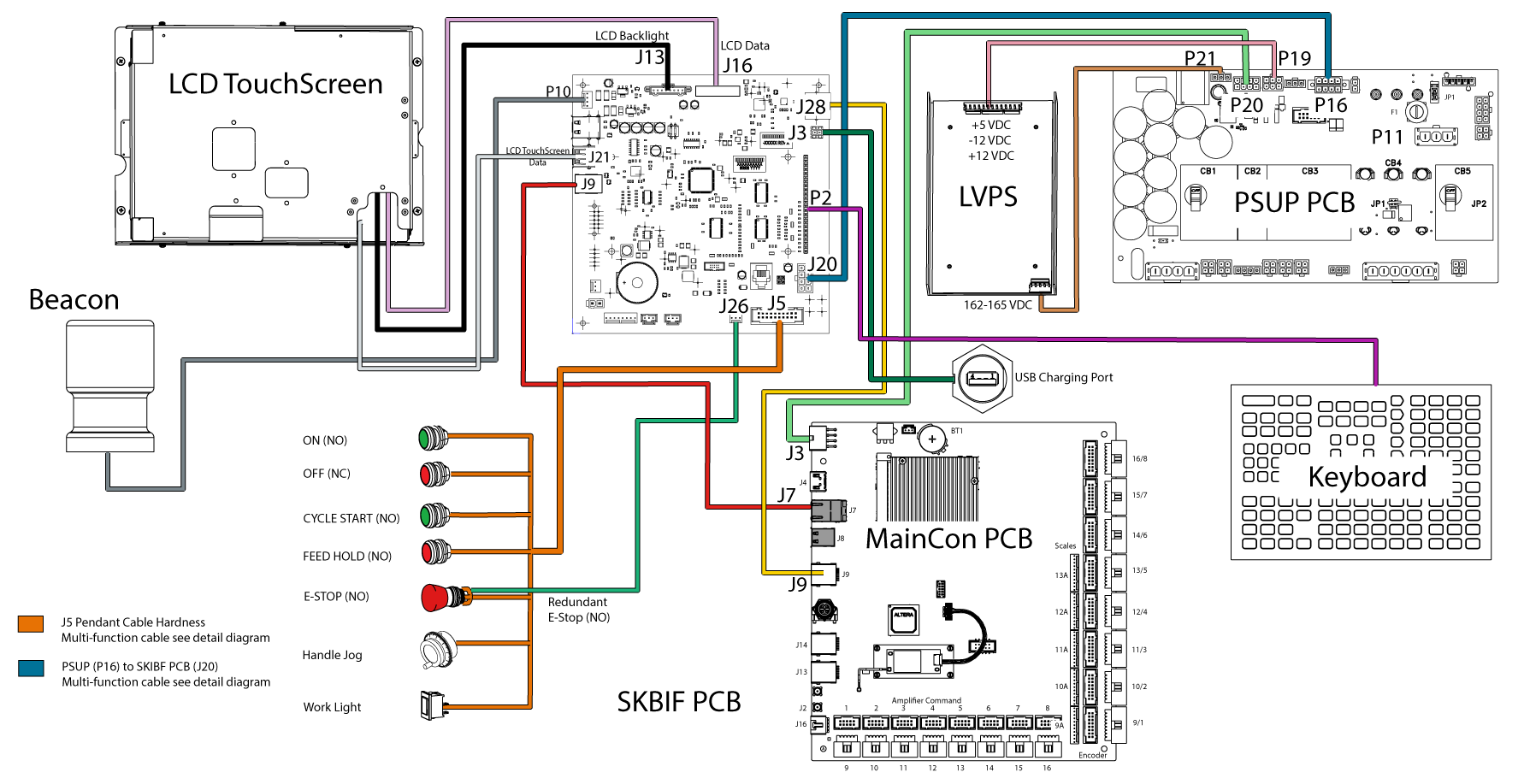
SKBIF / 15" LCD Interconnect Diagram

SKBIF Diagram P/N 34-4243G 


SKBIF Diagram P/N 34-4510/B

Note: Machines with SKBIF 34-4510B and a USB Charging Port  will have the USB Charging Port connected to J20 on the SKBIF. The Charging Port is only for charging purposes and not for getting data from USB devices.


SKBIF Diagram P/N 34-4510C

Note: Machines with SKBIF 34-4510C will have the USB Charging Port connected to J3. The Charging Port is only for charging purposes and not for getting data from USB devices.

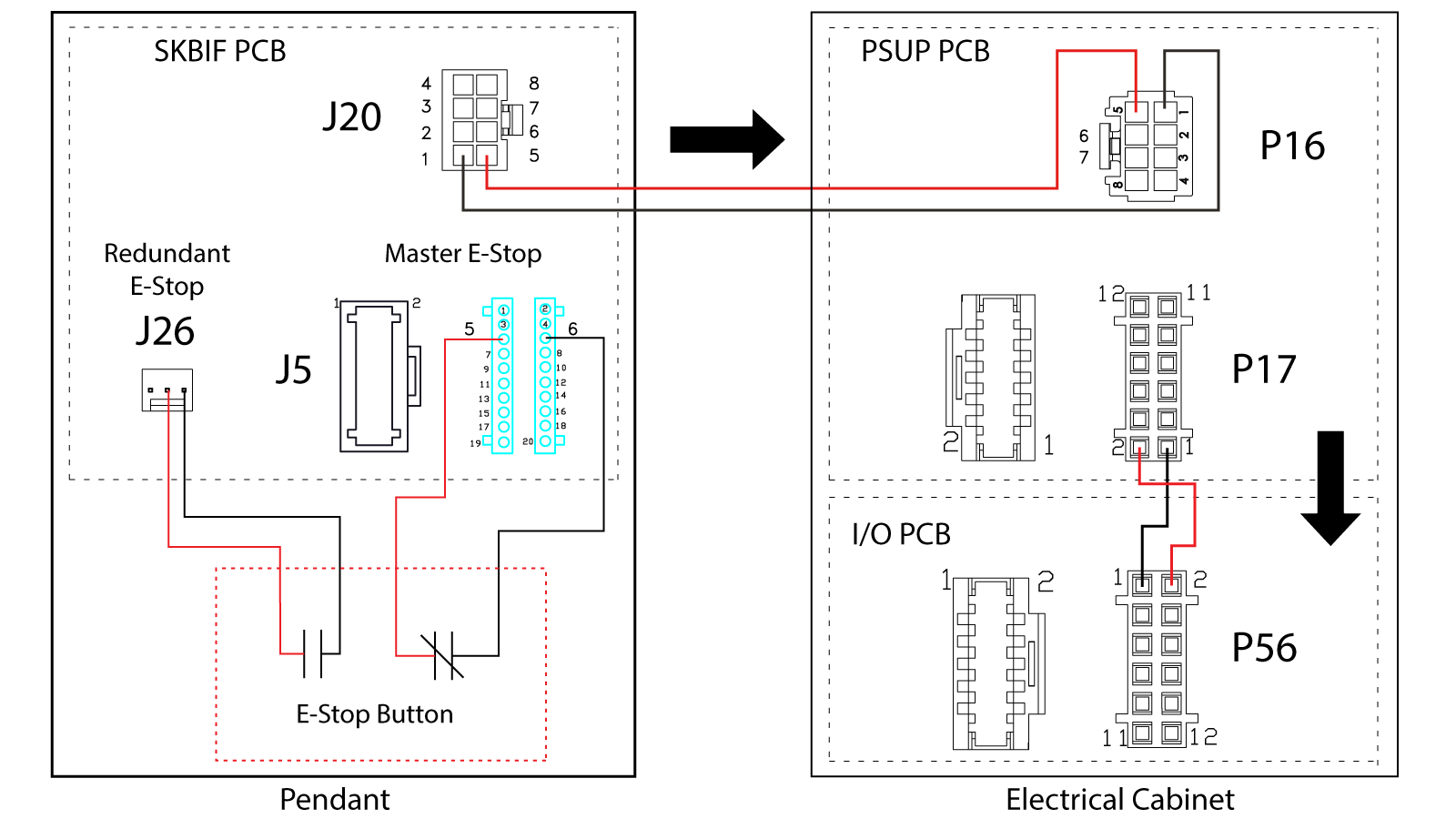
Pendant E-Stop Circuit Diagram

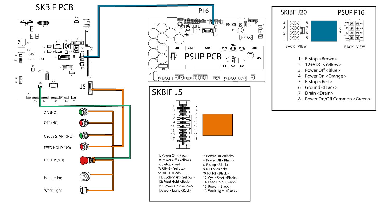
PSUP (P16) to SKBIF (J5) Detailed Diagram

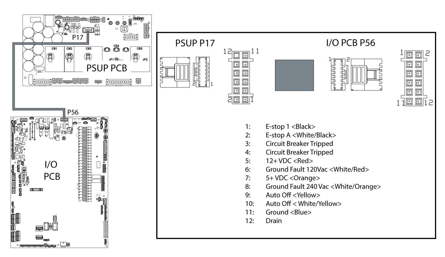
PSUP (P17) to I/O PCB (P56) Detailed Diagram

Recently Viewed Items

You Have No Recently Viewed Items Yet

Feedback
Haas Logo

Haas Delivered Price

This price includes shipping cost, export and import duties, insurance, and any other expenses incurred during shipping to a location in France agreed with you as a buyer. No other mandatory costs can be added to the delivery of a Haas CNC Product.

KEEP UP WITH THE LATEST HAAS TIPS AND TECHNOLOGY...

Sign up now!   

HAAS TOOLING ACCEPTS THE FOLLOWING:

  • Service & Support
  • Owners
  • Request Service
  • Operator Manuals
  • Haas Parts
  • Rotary Repair Request
  • Pre-Install Guides
  • Shopping Tools
  • Build & Price a New Haas
  • Available Inventory
  • The Haas Price List
  • CNCA Financing
  • About Haas
  • Accessibility Statement
  • DNSH Statement
  • Export Compliance
  • Careers
  • Certifications & Safety
  • Contact Us
  • History
  • Terms & Conditions
  • Haas Tooling Terms & Conditions
  • Privacy
  • Warranty
  • Haas Community
  • Haas Certification Program
  • Haas Motorsports
  • Gene Haas Foundation
  • Haas Technical Education Community
  • Events
  • Join the Conversation
  • Facebook
  • X
  • Flickr
  • YouTube
  • LinkedIn
  • Instagram
  • TikTok
© 2026 Haas Automation, Inc – CNC Machine Tools

This site is protected by reCAPTCHA and the Google Privacy Policy and Terms of Service apply.

2800 Sturgis Rd., Oxnard, CA 93030
Toll Free: (888) 817-4446 / Fax: 805-278-8554